XFP10GLR192SRRGD - Network card / adapter CISCO - Free user manual and instructions
Find the device manual for free XFP10GLR192SRRGD CISCO in PDF.
| Product Type | 10 Gigabit XFP Transceiver Module |
| Brand | Cisco |
| Model | XFP10GLR192SRRGD |
| Connector | Duplex LC |
| Fiber Type | Single Mode (SMF) |
| Maximum Distance | 10 km |
| Wavelength | 1310 nm |
| Data Rate | 10 Gbps |
| Power Supply | 3.3 V (via host connector) |
| Power Consumption | < 2.5 W |
| Dimensions | 85 mm x 18.4 mm x 8.5 mm |
| Weight | approx. 50 g |
| Operating Temperature | 0°C to 70°C |
| Humidity | 5% to 95% (non-condensing) |
| Certification | Class 1 Laser (IEC 60825-1) |
| Key Features | 10 Gigabit Ethernet optical transmission and reception, compatible with Cisco switches, hot-pluggable, digital monitoring (DDM). |
| Maintenance and Cleaning | Clean optical connectors with a suitable cleaning kit; do not use solvents; avoid touching fiber ends. |
| Safety | Class 1 laser product; do not look directly into the beam; follow electrical safety instructions. |
| Spare Parts and Repairability | No user-serviceable parts; if malfunctioning, replace the module. |
Frequently Asked Questions - XFP10GLR192SRRGD CISCO
User questions about XFP10GLR192SRRGD CISCO
0 question about this device. Answer the ones you know or ask your own.
Ask a new question about this device
Download the instructions for your Network card / adapter in PDF format for free! Find your manual XFP10GLR192SRRGD - CISCO and take your electronic device back in hand. On this page are published all the documents necessary for the use of your device. XFP10GLR192SRRGD by CISCO.
USER MANUAL XFP10GLR192SRRGD CISCO
natural_image
Black-and-white photo of a man sitting on a sofa, looking upward (no text or symbols visible)Cisco 10-Gigabit XFP Transceiver Modules Installation Note
Revised: February 3, 2012
Product Numbers:
XFP-10G-MM-SR= XFP-10GLR-OC192SR= XFP10GLR-192SR-L= XFP-10GER-OC192IR= XFP-10GER-192IR+= XFP10GER-192IR-L= XFP-10GZR-OC192LR= DWDM-XFP-xx.xx= DWDM-XFP-C= XFP10GLR192SR-RGD= XFP10GER192IR-RGD= XFP10GZR192LR-RGD=
This installation note provides the installation instructions for the 10-Gigabit XFP transceiver modules, which are hot-swappable input/output (I/O) devices that plug into a 10-Gigabit port. The XFP transceiver modules connect the system module port with a fiber-optic network.
This document contains these sections:
- Overview, page 2
- Safety, page 11
• Required Tools, page 17
• Installing the 10-Gigabit XFP Transceiver Module, page 17 - Removing the 10-Gigabit XFP Transceiver Module, page 19
• Translated Safety Warnings, page 21
• Related Documentation, page 26 - Obtaining Documentation and Submitting a Service Request, page 27
Overview
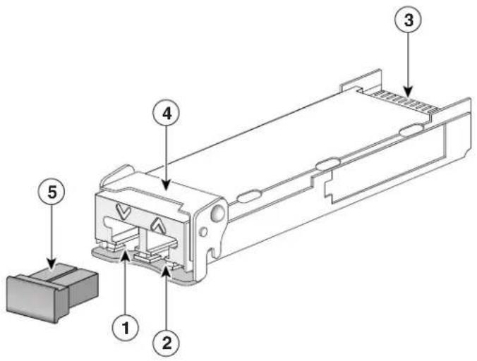
The 10-Gigabit XFP transceiver module is a hot-swappable I/O device that plugs into 10-Gigabit ports. (See Figure 1.) The XFP transceiver module connects the electrical circuitry of the system with the optical network.
Figure 1 10-Gigabit XFP Transceiver Module
text_image
Technical diagram of a mechanical component with numbered parts labeled 1 to 5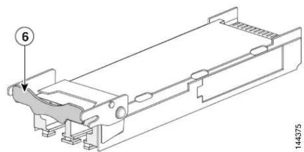
text_image
6 144375| 1 | Transmit optical bore | 4 | Bail clasp (locked position) |
| 2 | Receive optical bore | 5 | Dust plug |
| 3 | Transceiver socket connector | 6 | Bail clasp (unlocked position) |
The different XFP transceiver module types are listed in Table 1 and Table 2.
Table 1 10-Gigabit XFP Transceiver Modules
| XFP Transceiver Module Product Number | Description |
| XFP-10G-MM-SR= Cisco 10GBASE-SR XFP transceiver module for MMF, 850-nm wavelength, dual LC connector | |
| XFP-10GLR-OC192SR=XFP10GLR-192SR-L= | Cisco multirate XFP transceiver module for 10GBASE-LR Ethernet and OC-192/STM-64 short-reach (SR-1) Packet-over-SONET/SDH (POS) applications, SMF, dual LC connector |
| XFP10GLR192SR-RGD=C | isco multirate XFP transceiver module for 10GBASE-LR Ethernet and OC-192/STM-64 short-reach (SR-1) Packet-over-SONET/SDH (POS) applications, SMF, dual LC connector, industrial temperature range |
| XFP-10GER-OC192IR=XFP-10GER-192IR+=XFP10GER-192IR-L= | Cisco multirate XFP transceiver module for 10GBASE-ER Ethernet and OC-192/STM-64 intermediate-reach (IR-2) Packet-over-SONET/SDH (POS) applications, SMF, dual LC connector |
| XFP10GER192IR-RGD=C | isco multirate XFP transceiver module for 10GBASE-ER Ethernet and OC-192/STM-64 intermediate-reach (IR-2) Packet-over-SONET/SDH (POS) applications, SMF, dual LC connector, industrial temperature range |
| XFP-10GZR-OC192LR=C | isco multirate XFP transceiver module for 10GBASE-LR Ethernet and OC-192/STM-64 long-reach Packet-over-SONET/SDH (POS) applications, SMF, dual LC connector |
| XFP10GZR192LR-RGD=C | isco multirate XFP transceiver module for 10GBASE-LR Ethernet and OC-192/STM-64 long-reach Packet-over-SONET/SDH (POS) applications, SMF, dual LC connector, industrial temperature range |
Table 2 10-Gigabit Dense-Wavelength Division-Multiplexing (DWDM) XFP Transceiver Modules
| Transceiver Module Product Number | Description ITU | Channel |
| DWDM-XFP-60.61= 10 | GBASE-DWDM 1560.61 nm XFP (100-GHz ITU grid) 21 | |
| DWDM-XFP-59.79= 10 | GBASE-DWDM 1559.79 nm XFP (100-GHz ITU grid) 22 | |
| DWDM-XFP-58.98= 10 | GBASE-DWDM 1558.98 nm XFP (100-GHz ITU grid) 23 | |
| DWDM-XFP-58.17= 10 | GBASE-DWDM 1558.17 nm XFP (100-GHz ITU grid) 24 | |
| DWDM-XFP-56.55= 10 | GBASE-DWDM 1556.55 nm XFP (100-GHz ITU grid) 26 | |
| DWDM-XFP-55.75= 10 | GBASE-DWDM 1555.75 nm XFP (100-GHz ITU grid) 27 | |
| DWDM-XFP-54.94= 10 | GBASE-DWDM 1554.94 nm XFP (100-GHz ITU grid) 28 | |
| DWDM-XFP-54.13= 10 | GBASE-DWDM 1554.13 nm XFP (100-GHz ITU grid) 29 | |
| DWDM-XFP-52.52= 10 | GBASE-DWDM 1552.52 nm XFP (100-GHz ITU grid) 31 | |
| DWDM-XFP-51.72= 10 | GBASE-DWDM 1551.72 nm XFP (100-GHz ITU grid) 32 | |
| DWDM-XFP-50.92= 10 | GBASE-DWDM 1550.92 nm XFP (100-GHz ITU grid) 33 | |
| DWDM-XFP-50.12= 10 | GBASE-DWDM 1550.12 nm XFP (100-GHz ITU grid) 34 | |
| DWDM-XFP-48.51= 10 | GBASE-DWDM 1548.51 nm XFP (100-GHz ITU grid) 36 | |
| DWDM-XFP-47.72= 10 | GBASE-DWDM 1547.72 nm XFP (100-GHz ITU grid) 37 | |
| DWDM-XFP-46.92= 10 | GBASE-DWDM 1546.92 nm XFP (100-GHz ITU grid) 38 | |
| DWDM-XFP-46.12= 10 | GBASE-DWDM 1546.12 nm XFP (100-GHz ITU grid) 39 | |
| DWDM-XFP-44.53= 10 | GBASE-DWDM 1544.53 nm XFP (100-GHz ITU grid) 41 | |
| DWDM-XFP-43.73= 10 | GBASE-DWDM 1543.73 nm XFP (100-GHz ITU grid) 42 | |
| DWDM-XFP-42.94= 10 | GBASE-DWDM 1542.94 nm XFP (100-GHz ITU grid) 43 | |
| DWDM-XFP-42.14= 10 | GBASE-DWDM 1542.14 nm XFP (100-GHz ITU grid) 44 | |
| DWDM-XFP-40.56= 10 | GBASE-DWDM 1540.56 nm XFP (100-GHz ITU grid) 46 | |
| DWDM-XFP-39.77= 10 | GBASE-DWDM 1539.77 nm XFP (100-GHz ITU grid) 47 | |
| DWDM-XFP-38.98= 10 | GBASE-DWDM 1538.98 nm XFP (100-GHz ITU grid) 48 | |
| DWDM-XFP-38.19= 10 | GBASE-DWDM 1538.19 nm XFP (100-GHz ITU grid) 49 | |
| DWDM-XFP-36.61= 10 | GBASE-DWDM 1536.61 nm XFP (100-GHz ITU grid) 51 | |
| DWDM-XFP-35.82= 10 | GBASE-DWDM 1535.82 nm XFP (100-GHz ITU grid) 52 | |
| DWDM-XFP-35.04= 10 | GBASE-DWDM 1535.04 nm XFP (100-GHz ITU grid) 53 | |
| DWDM-XFP-34.25= 10 | GBASE-DWDM 1534.25 nm XFP (100-GHz ITU grid) 54 | |
| DWDM-XFP-32.68= 10 | GBASE-DWDM 1532.68 nm XFP (100-GHz ITU grid) 56 | |
| DWDM-XFP-31.90= 10 | GBASE-DWDM 1531.90 nm XFP (100-GHz ITU grid) 57 | |
| DWDM-XFP-31.12= 10 | GBASE-DWDM 1531.12 nm XFP (100-GHz ITU grid) 58 | |
| DWDM-XFP-30.33= 10 | GBASE-DWDM 1530.33 nm XFP (100-GHz ITU grid) 59 | |
| DWDM-XFP-C= 10 | BASE-DWDM tuneable XFP (50-GHz ITU grid) See | Table 3 |

The dual LC connector on the XFP transceivers support network interface cables with either Physical Contact (PC) or Ultra-Physical Contact (UPC) polished face types. The dual LC connectors on the XFP transceivers do not support network interface cables with an Angle Polished Connector (APC) polished face type.
Table 3 lists the 80 DWDM ITU 50-GHz channels available to the tuneable XFP transceiver modules.
Table 3 ITU 50-GHz Center Wavelengths and Channel Numbering
| Channel ID Frequency (THz) | Wavelength (nm) | Channel ID Frequency (THz) | Wavelength (nm) | |||
| 80 | 195.9 1530.33 | 79 | 195.85 | 1530.72 | ||
| 78 | 195.8 1531.12 | 77 | 195.75 | 1531.51 | ||
| 76 | 195.7 1531.90 | 75 | 195.65 | 1532.29 | ||
| 74 | 195.6 1532.68 | 73 | 195.55 | 1533.07 | ||
Cisco 10-Gigabit XFP Transceiver Modules Installation Note
Table 3 ITU 50-GHz Center Wavelengths and Channel Numbering (continued)
| Channel ID Frequency (THz) | Wavelength (nm) | Channel ID Frequency (THz) | Wavelength (nm) | ||||
| 72 | 195.5 | 1533.47 | 71 195.45 1533 | 86 | |||
| 70 | 195.4 | 1534.25 | 69 195.35 1534 | 64 | |||
| 68 | 195.3 | 1535.04 | 67 195.25 1535 | 43 | |||
| 66 | 195.2 | 1535.82 | 65 195.15 1536 | 22 | |||
| 64 | 195.1 | 1536.61 | 63 195.05 1537 | 00 | |||
| 62 | 195.0 | 1537.40 | 61 194.95 1537 | 79 | |||
| 60 | 194.9 | 1538.19 | 59 194.85 1538 | 58 | |||
| 58 | 194.8 | 1538.98 | 57 194.75 1539 | 37 | |||
| 56 | 194.7 | 1539.77 | 55 194.65 1540 | 16 | |||
| 54 | 194.6 | 1540.56 | 53 194.55 1540 | 95 | |||
| 52 | 194.5 | 1541.35 | 51 194.45 1541 | 75 | |||
| 50 | 194.4 | 1542.14 | 49 194.35 1542 | 54 | |||
| 48 | 194.3 | 1542.94 | 47 194.25 1543 | 33 | |||
| 46 | 194.2 | 1543.73 | 45 194.15 1544 | 13 | |||
| 44 | 194.1 | 1544.53 | 43 194.05 1544 | 92 | |||
| 42 | 194.0 | 1545.32 | 41 193.95 1545 | 72 | |||
| 40 | 193.9 | 1546.12 | 39 193.85 1546 | 52 | |||
| 38 | 193.8 | 1546.92 | 37 193.75 1547 | 32 | |||
| 36 | 193.7 | 1547.72 | 35 193.65 1548 | 11 | |||
| 34 | 193.6 | 1548.51 | 33 193.55 1548 | 91 | |||
| 32 | 193.5 | 1549.32 | 31 193.45 1549 | 72 | |||
| 30 | 193.4 | 1550.12 | 29 193.35 1550 | 52 | |||
| 28 | 193.3 | 1550.92 | 27 193.25 1551 | 32 | |||
| 26 | 193.2 | 1551.72 | 25 193.15 1552 | 12 | |||
| 24 | 193.1 | 1552.52 | 23 193.05 1552 | 93 | |||
| 22 | 193.0 | 1553.33 | 21 192.95 1553 | 73 | |||
| 20 | 192.9 | 1554.13 | 19 192.85 1554 | 54 | |||
| 18 | 192.8 | 1554.94 | 17 192.75 1555 | 34 | |||
| 16 | 192.7 | 1555.75 | 15 192.65 1556 | 15 | |||
| 14 | 192.6 | 1556.55 | 13 192.55 1556 | 96 | |||
| 12 | 192.5 | 1557.36 | 11 192.45 1557 | 77 | |||
| 10 | 192.4 | 1558.17 | 9 192.35 1558.58 | ||||
| 8 | 192.3 | 1558.98 | 7 192.25 1559.39 | ||||
| 6 | 192.2 | 1559.79 | 5 192.15 1560.20 | ||||
Table 3 ITU 50-GHz Center Wavelengths and Channel Numbering (continued)
| Channel ID Frequency (THz) | Wavelength (nm) | Channel ID Frequency (THz) | Wavelength (nm) |
| 4 192.1 1560.61 | 3 192.05 1561.01 | ||
| 2 192.0 1561.42 | 1 191.95 1561.83 |
Table 4 lists the port cabling specifications for the 10-Gigabit XFP transceiver modules.
Table 4 XFP Transceiver Port Cabling Specifications
| XFP Product Number Nominal | Wavelength(nm) | Cable Type Core | Size(microns) | ModalBandwidth(MHz/km) | Maximum Cabling Distance |
| XFP-10G-MM-SR= 850 MMF | 62.5 | 62.5 | 160 | 26 m (85.3 ft) | |
| 200 | 33 m (108.3 ft) | ||||
| 50.0 | 400 | 66 m (216.5 ft) | |||
| 50.0 | 500 | 82 m (269 ft) | |||
| 50.0 | 2000 | 300 m (984.3 ft) | |||
| XFP-10GLR-OC192SR=XFP10GLR-192SR-L=XFP10GLR192SR-RGD= | 1310 | SMF | G.652 | — | 10 km (6.2 miles) |
| 10-Gigabit Ethernet | |||||
| 2 km (1.24 miles) | |||||
| OC-192/STM-64 SR1 | |||||
| XFP-10GER-OC192IR=XFP-10GER-192IR+=XFP10GER-192IR-L=XFP10GER192IR-RGD= | 1550 | SMF | G.652 | — | 40 km (24.86 miles) |
| XFP-10GZR-OC192LR=XFP10GZR192LR-RGD= | 1550 | SMF | G.652 | — | 80 km (49.70 miles) |
| DWDM-XFP-xx.xx= | See Table 2on page 3 | SMF | G.652 | — | 80 km (49.70 miles) |
| DWDM-XFP-C= | See Table 3on page 4 | SMF | G.652 | — | 80 km (49.70 miles) |
Table 5 lists the XFP transceiver modules optical transmit and receive specifications.
Table 5 XFP Transceiver Optical Transmit and Receive Specifications
| XFP Product Number Transceiver Operating Mode Transmit Power | (dBm) | Receive Power (dBm) | Transmit and Receive Wavelength (nm) | |
| XFP-10G-MM-SR= 10GBASE-SR, 850-nm MMF(10.3125-Gbps line rate) | -1.0 (Max)-7.3 (Min) | -1.2 (Max)-9.9 (Min) | 840 to 860(TX and RX) | |
| XFP-10GLR-OC192SR=XFP10GLR-192SR-L=XFP10GLR192SR-RGD= | 10GBASE-LR, 1310-nm SMF(10.3125-Gbps line rate) | +0.5 (Max)-8.2 (Min) | +0.5 (Max)-14.4 (Min) | 1260 to 1355 (TX)1260 to 1565 (RX) |
| OC-192/STM-64 SR1, 1310-nm SMF(9.95328-Gbps line rate) | -1.0 (Max)-6.0 (Min) | -1.0 (Max)-11.0 (Min) | 1290 to 1330 (TX)1260 to 1565 (RX) | |
| XFP-10GER-OC192IR=XFP-10GER-192IR+=XFP10GER-192IR-L=XFP10GER192IR-RGD= | 10GBASE-ER, 1550-nm SMF(10.3125-Gbps line rate) | +4.0 (Max)-4.7 (Min) | -1.0 (Max)-15.8 (Min) | 1530 to 1565 (TX)1260 to 1565 (RX) |
| OC-192/STM-64 IR2, 1550-nm SMF(9.95328-Gbps line rate) | +2.0 (Max)-1.0 (Min) | +2.0 (Max)-14.0 (Min) | 1530 to 1565 (TX)1260 to 1565 (RX) | |
| XFP-10GZR-OC192LR=XFP10GZR192LR-RGD= | 10GBASE-ZR, 1550-nm SMF(10.3125-Gbps line rate)OC-192/STM-64 LR2, 1550-nm SMF(9.95328-Gbps line rate) | +4.0 (Max)0 (Min) | -7.0 (Max)-24 (Min) | 1530 to 1565 (TX)1260 to 1565 (RX) |
Table 6 lists the optical specifications of the DWDM XFP transceiver modules.
Table 6 DWDM XFP Optical Transmit and Receive Specifications
| Parameter Symbol | Minimum Typical Maximum Units Notes and Conditions | |||||
| Transmitter | ||||||
| Spectral Width — | — 0.2 nm Full width, -20 dB from maximum, with resolution bandwidth (RBW) = 0.01 nm | |||||
| Transmitter center wavelength | — | x^1 - 100 | x | x^1 + 100 | pm | See Table 2 for center wavelengths |
| Side-mode suppression ratio | SMSR | 30 | — | — | dB | — |
| Transmitter extinction ratio | OMI | 9 | — | — | dB | — |
| Transmitter optical output power | Pout | -1.0 | — | 3.0 | dBm | Average power coupled into single-mode fiber |
| Receiver | ||||||
| Receiver optical input wavelength | — | 1530 | — | 1565 | nm | — |
| Receiver damage threshold | — | — | — | 4.0 | dBm | — |
| Dispersion tolerance | — | -500 | — | 1600 | ps/nm | — |
| Power-Limited Performance (measured at optical signal-to-noise ratio [OSNR] of 30 dB at 0.1-nm RBW) | ||||||
| Optical input power | Pin | -23.0 | — | -7.0 | dBm | Measured at a bit error rate (BER) = 1E-12 with an IEEE 802.3 test pattern |
| Dispersion power penalty | — — — 3 | dB | Measured at a bit error rate (BER) = 1E-12 with an IEEE 802.3 test pattern | |||
| Noise-Limited Performance (measured at OSNR of 24 dB at 0.1-nm RBW) | ||||||
| Optical input power | Pin | -18.0 | — | -7.0 | dB | Measured at a bit error rate (BER) = 1E-12 with an IEEE 802.3 test pattern |
| Dispersion OSNR penalty | — — — 3 | dB | Measured at a bit error rate (BER) = 1E-12 with an IEEE 802.3 test pattern | |||
- x is the center wavelength. The center wavelength can vary ±100 picometers (pm).
Table 7 and Table 8 list the optical specifications of the tuneable DWDM XFP transceiver modules (DWDM-XFP-C=).
Table 7 Tuneable DWDM XFP Optical Transmit and Receive Specifications
| Parameter Symbol | Minimum | Typical | Maximum Units | Notes and Conditions | ||
| Transmitter | ||||||
| Spectral Width | — | — | — | 0.2 | nm | Full width, -20 dB from maximum, with resolution bandwidth (RBW) = 0.01 nm. |
| Transmitter center wavelength | — | x^1-25 | x | x^1+25 | pm | See Table 2 for center wavelengths. |
| Side-mode suppression ratio | SMSR | 30 | — | — | dB | — |
| Transmitter extinction ratio | OMI | 9 | — | — | dB | — |
| Transmitter optical output power | Pout | 0.0 | — | 3.0 | dBm | Average power coupled into single-mode fiber |
| Receiver | ||||||
| Receiver optical input wavelength | — | 1530 | — | 1565 | nm | — |
| Receiver damage threshold | — | — | — | 4.0 | dBm | — |
| Dispersion tolerance | — | -500 | — | 1600 | ps/nm | — |
| Power-Limited Performance (measured at optical signal-to-noise ratio [OSNR] of 30 dB at 0.1-nm RBW) | ||||||
| Optical input power | Pin | -23.0 | — | -7.0 | dBm | Measured at a bit error rate (BER) = 1E-12 with an IEEE 802.3 test pattern |
| Dispersion power penalty | — — — 3 | dB | Measured at a bit error rate (BER) = 1E-12 with an IEEE 802.3 test pattern | |||
| Noise-Limited Performance (measured at OSNR of 24 dB at 0.1-nm RBW) | ||||||
| Optical input power | Pin | -18.0 | — | -7.0 | dB | Measured at a bit error rate (BER) = 1E-12 with an IEEE 802.3 test pattern |
| Dispersion OSNR penalty | — — — 3 | dB | Measured at a bit error rate (BER) = 1E-12 with an IEEE 802.3 test pattern | |||
- x is the center wavelength. The center wavelength can vary ±25 picometers (pm).
Table 8 Receiver Power Performance
| Units Range Notes and Conditions | |||
| Long Wavelength Performances C Band, No-FEC Applications, Power-Limited | |||
| Input power range dBm | 7 to -24 At BER | = 1E-12 | applicable at 9.9 G and 10.3 G, 30-dB OSNR (0.1-nm RBW) |
| Input power range dBm | 7 to -22 At BER | = 1E-12 | (-500 to +1600 ps/nm) applicable at 9.9 G and 10.3 G, 30-dB OSNR (0.1-nm RBW) |
| Long Wavelength Performances C Band, No-FEC Applications, Noise-Limited | |||
| Input power range dBm | 7 to -22 At BER | = 1E-12 | applicable at 9.9 G and 10.3 G, 26-dB OSNR (0.1-nm RBW) |
| Input power range dBm | 7 to -20 At BER | = 1E-12 | (-500 to +1600 ps/nm) applicable at 9.9 G and 10.3 G, 30-dB OSNR (0.1-nm RBW) |
| Long Wavelength Performances C Band FEC Applications Noise-Limited | |||
| Input power range dBm | 7 to -18 At BER | PREFEC < 1E-5 | applicable at 10.7 G and 11.1 G, 15.5-dB OSNR (0.1-nm RBW) |
| Input power range dBm | 7 to -18 At BER | PREFEC < 1E-5 | (-500 to +1000 ps/nm) applicable at 10.7 G and 11.1 G, 17-dB OSNR (0.1-nm RBW) |
| Long Wavelength Performances C Band E-FEC Applications Power-Limited | |||
| Input power range dBm | 7 to -27 At BER | PREFEC < 7E-4 | applicable at 10.7 G and 11.1 G, 26-dB OSNR (0.1-nm RBW) |
| Input power range dBm | 7 to -26 At BER | PREFEC < 7E-4 | (-500 to +1300 ps/nm) applicable at 10.7 G and 11.1 G, 26-dB OSNR (0.1-nm RBW) |
| Long Wavelength Performances C Band E-FEC Applications Noise-Limited | |||
| Input power range dBm | 7 to -20 At BER | PREFEC < 7E-4 | applicable at 10.7G and 11.1G, 12 dB OSNR (0.1-nm RBW) |
| Input power range | dBm | -7 to -20 | At BER PREFEC < 7E-4 (-500 to +1300 ps/nm) applicable at 10.7 G and 11.1 G, 14-dB OSNR (0.1-nm RBW) |
Safety
Safety warnings appear throughout this publication in procedures that may harm you if performed incorrectly or are ignored. A warning symbol precedes each warning statement.
Statement 1071—Warning Definition

IMPORTANT SAFETY INSTRUCTIONS
This warning symbol means danger. You are in a situation that could cause bodily injury. Before you work on any equipment, be aware of the hazards involved with electrical circuitry and be familiar with standard practices for preventing accidents. Use the statement number provided at the end of each warning to locate its translation in the translated safety warnings that accompanied this device.
SAVE THESE INSTRUCTIONS
Waarschuwing
BELANGRIJKE VEILIGHEIDSINSTRUCTIES
USCHOVEJTE TYTO POKYNY
DÔLEŽITÉ BEZPEČNOSTNÉ POKYNY
USCHOVAJTE SI TENTO NÁVOD

Because invisible laser radiation may be emitted from the aperture of the port when no cable is connected, avoid exposure to laser radiation and do not stare into open apertures. Statement 70

Class 1 laser product. Statement 1008

Ultimate disposal of this product should be handled according to all national laws and regulations. Statement 1040

Use of controls, adjustments, or performing procedures other than those specified may result in hazardous radiation exposure. Statement 1057
Required Tools
You will need these tools to install the 10-Gigabit XFP transceiver modules:
- Wrist strap or other personal grounding device to prevent ESD occurrences.
- Antistatic mat or antistatic foam to set the transceiver on.
- Fiber-optic end-face cleaning tools and inspection equipment. For complete information on inspecting and cleaning fiber-optic connections, see the white-paper document at this URL:
http://www.cisco.com/en/US/tech/tk482/tk876/technologies_white_paper09186a0080254eba.shtml
Installing the 10-Gigabit XFP Transceiver Module
Caution
The XFP transceiver module is a static-sensitive device. Always use an ESD wrist strap or similar individual grounding device when handling XFP transceiver modules or coming into contact with system modules.
To install an XFP transceiver module, follow these steps:
Step 1 Remove the XFP transceiver module from its protective packaging.

Note Do not remove the optical bore dust plugs until directed to do so later in the procedure.
Step 2 Check the label on the XFP transceiver module body to verify that you have the correct model for your network.
Step 3 Position the XFP transceiver module in front of the XFP socket opening on the line card. Slide the XFP transceiver module part of the way into the transceiver socket on the line card front panel.
Step 4 Remove the optical bore dust plug from the XFP transceiver module.
Step 5 Pivot the bail clasp up so that it is parallel with the transceiver module body. (See Figure 2, top view.)
Step 6 Continue sliding the XFP transceiver module into the socket until the XFP transceiver module is mated with the socket connector.
Step 7 Latch the XFP transceiver module in the transceiver socket by pivoting the bail clasp down so that the bail clasp is perpendicular to the transceiver body. (See Figure 2, bottom view.)
Caution
Caution If the latch is not fully engaged, you may accidentally disconnect the XFP transceiver module.
Step 8 Immediately reinstall the dust plug in the XFP transceiver module optical bores. Do not remove the dust plug until you are ready to attach the network interface cable.
Figure 2 Installing the 10-Gigabit XFP Transceiver Module
text_image
Diagram illustrating the installation of a fuse with labeled components and wiring connections
Note 10-Gigabit XFP transceiver modules are keyed to prevent incorrect insertion.
Before removing the dust plugs and making any optical connections, follow these guidelines:
- Keep the protective dust plugs installed in the unplugged fiber-optic cable connectors and the transceiver optical bores until you are ready to make a connection.
- Inspect and clean the LC connector end faces just before you make any connections. See the Tip on this page for a pointer to a fiber-optic inspection and cleaning white paper.
- Grasp the LC connector only by the housing to plug or unplug a fiber-optic cable.
a. Remove the dust plugs from the optical network interface cable LC connectors. Save the dust plugs for future use.
b. Inspect and clean the LC connector's fiber-optic end faces. See the Tip on this page for a pointer to a fiber-optic inspection and cleaning white paper.
Tip For complete information on inspecting and cleaning fiber-optic connections, see this URL: http://www.cisco.com/en/US/tech/tk482/tk876/technologies_white_paper09186a0080254eba.shtml
c. Remove the dust plugs from the XFP transceiver module optical bores.
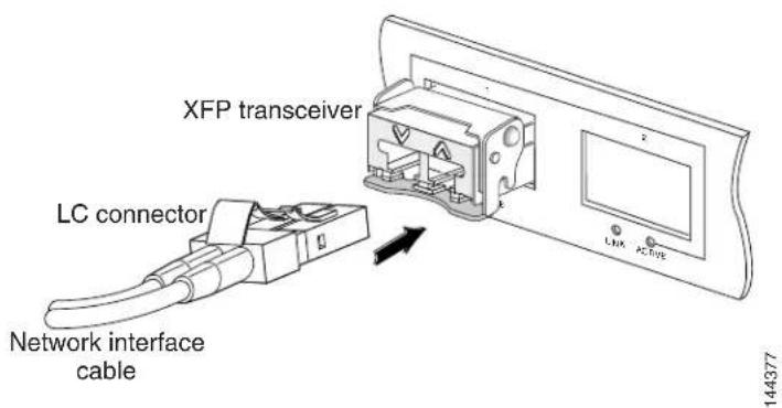
d. Immediately attach the network interface cable LC connectors to the XFP transceiver module. (See Figure 3.)
Figure 3 Cabling a 10-Gigabit XFP Transceiver Module
text_image
XFP transceiver LC connector Network interface cable 144377Removing the 10-Gigabit XFP Transceiver Module

Caution
The XFP transceiver module is a static-sensitive device. Always use an ESD wrist strap or similar individual grounding device when handling XFP transceiver modules or coming into contact with modules.
If you are removing an XFP transceiver, follow these steps:
Step 1 Disconnect the network interface cable from the XFP transceiver module connectors. Immediately reinstall the dust plug in the fiber-optic cable LC connector.
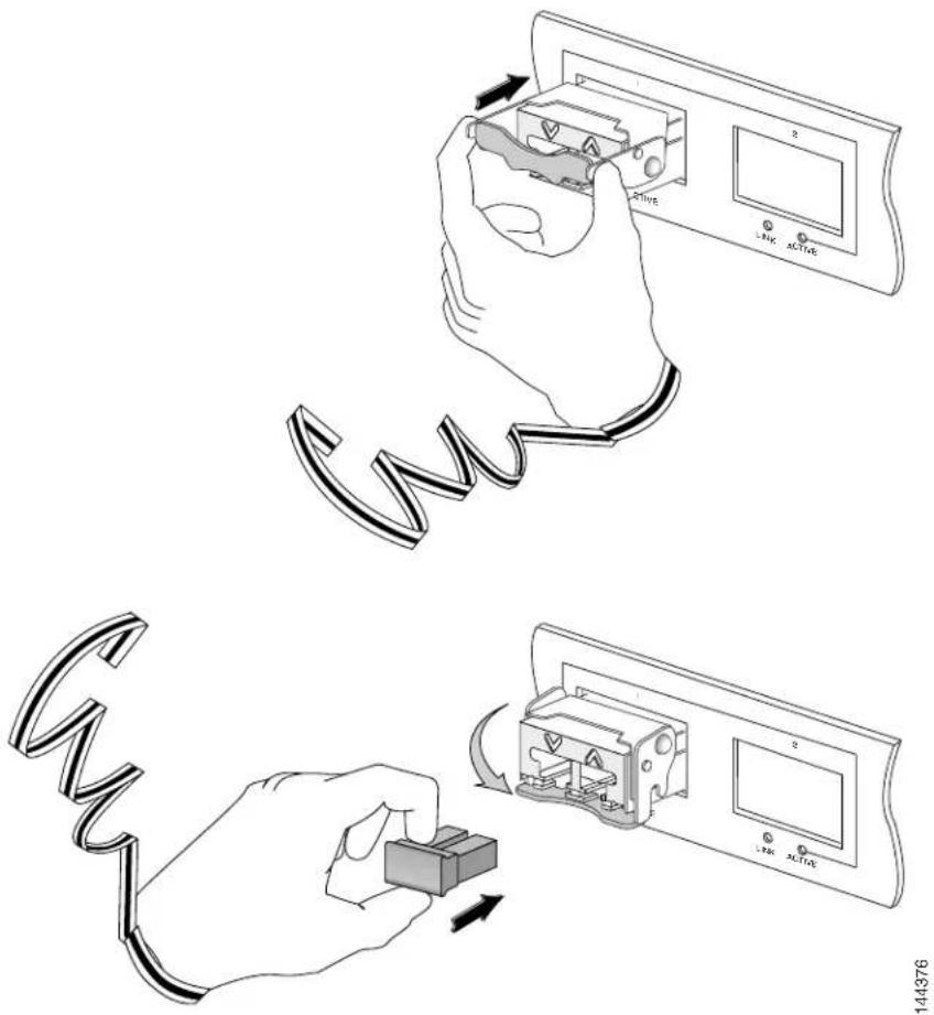
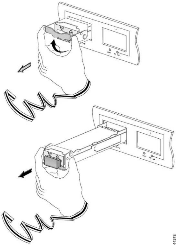
Step 2 Pivot the XFP transceiver module bail clasp up to release the XFP transceiver module from the socket. (See Figure 4, top view.)
Step 3 Slide the XFP transceiver module out of the socket. Pivot the bail clasp down and immediately install the dust plug in the XFP transceiver module optical bores. (See Figure 4, bottom view.)
Step 4 Immediately place the XFP transceiver module in an antistatic bag.
Figure 4 Removing the 10-Gigabit XFP Transceiver Module
text_image
Diagram illustrating the process of inserting a cable into an electronic device, showing hand positioning and control buttons.Translated Safety Warnings
This section repeats in multiple languages the basic warnings that appear in this document.
Statement 70—Invisible Laser Radiation Warning
| Warning | Because invisible laser radiation may be emitted from the aperture of the port when no cable is connected, avoid exposure to laser radiation and do not stare into open apertures. |
| Waarschuwing | Omdat er onzichtbare laserstraling uit de opening van de poort geëmitteerd kan worden wanneer er geen kabel aangesloten is, dient men om blootstelling aan laserstraling te vermijden niet in de open openingen te kijken. |
| Varoitus | Kun porttiin ei ole kytketty kaapelia, portin aukosta voi vuotaa näkymätöntä lasersäteilyä. Älä katso avoimiin aukkoihin, jotta et altistu säteilylle. |
| Attention | Etant donné qu’un rayonnement laser invisible peut être émis par l’ouverture du port quand aucun câble n’est connecté, ne pas regarder dans les ouvertures béantes afin d’éviter tout risque d’exposition au rayonnement laser. |
| Warnung | Aus der Öffnung des Ports kann unsichtbare Laserstrahlung austreten, wenn kein Kabel angeschlossen ist. Kontakt mit Laserstrahlung vermeiden und nicht in offene Öffnungen blicken. |
| Avvertenza | Poiché quando nessun cavo è collegato alla porta, da quest’ultima potrebbe essere emessa radiazione laser invisibile, evitare l’esposizione a tale radiazione e non fissare con gli occhi porte a cui non siano collegati cavi. |
| Advarsel | Usynlige laserstråler kan sendes ut fra åpningen på utgangen när ingen kabel er tilkoblet. Unngå utsettelse for laserstråling og se ikke inn i åpninger som ikke er tildekket. |
| Aviso | Evite uma exposição à radiação laser e não olhe através de aberturas expostas, porque poderá ocorrer emissão de radiação laser invisível a partir da abertura da porta, quando não estiver qualquer cabo conectado. |
| ¡Advertencia! | Cuando no esté conectado ningún cable, pueden emitirse radiaciones láser invisibles por el orificio del puerto. Evitar la exposición a radiaciones láser y no mirar fijamente los orificios abiertos. |
| Varning! | Osynliga laserstrålar kan sändas ut från öppningen i porten när ingen kabel är ansluten. Undvik exponering för laserstrålning och titta inte in i ej täckta öppningar. |
Statement 1008—Class 1 Laser Product

Warning Class 1 laser product.
Waarschuwing Klasse-1 laser produkt.
Statement 1040—Product Disposal
| Warning | Ultimate disposal of this product should be handled according to all national laws and regulations. |
| Waarschuwing | Het uiteindelijke wegruimen van dit product dient te geschieden in overeenstemming met alle nationale wetten en reglementen. |
| Varoitus | Tämä tuote on hävitettävä kansallisten lakien ja määräysten mukaisesti. |
| Attention | La mise au rebut ou le recyclage de ce produit sont généralement soumis à des lois et/ou directives de respect de l'environnement. Renseignez-vous auprès de l'organisme compétent. |
| Warnung | Die Entsorgung dieses Produkts sollte gemäß allen Bestimmungen und Gesetzen des Landes erfolgen. |
| Avvertenza | Lo smaltimento di questo prodotto deve essere eseguito secondo le leggi e regolazioni locali. |
| Advarsel | Endelig kassering av dette produktet skal være i henhold til alle relevante nasjonale lover og bestemmelser. |
| Aviso | Deitar fora este produto em conformidade com todas as leis e regulamentos nacionais. |
| ¡Advertencia! | Al deshacerse por completo de este producto debe seguir todas las leyes y reglamentos nacionales. |
| Varning! | Vid deponering hanteras produkten enligt gällande lagar och bestämmelser. |
| Figyelem | A készülék végső elhelyezéséről az adott országban érvényes törvények és előírások szerint kell intézkedni. |
| Предупреждение | Окончательная установка данного изделия должна выполняться в соответствии со всеми региональными и местными правилами и нормами. |
Statement 1057—Hazardous Radiation Exposure

Warning
Use of controls, adjustments, or performing procedures other than those specified may result in hazardous radiation exposure.
Waarschuwing
Cisco 10-Gigabit XFP Transceiver Modules Installation Note
| Varoitus | Säätimien tai säätöjen käyttö ja toimenpiteiden suorittaminen ohjeista poikkeavalla tavalla voi altistaa vaaralliselle säteilylle. |
| Attention | L'utilisation de commandes, de réglages ou de procédures autres que ceux spécifiés peut entraîner une exposition dangereuse à des radiations. |
| Warnung | Die Verwendung von nicht spezifizierten Steuerelementen, Einstellungen oder Verfahrensweisen kann eine gefährliche Strahlenexposition zur Folge haben. |
| Avvertenza | L'adozione di controlli, regolazioni o procedure diverse da quelle specificate può comportare il pericolo di esposizione a radiazioni. |
| Advarsel | Bruk av kontroller eller justeringer eller utførelse av prosedyrer som ikke er spesifiserte, kan resultere i farlig strålingseksponering. |
| Aviso | O uso de controles, ajustes ou desempenho de procedimentos diferentes dos especificados pode resultar em exposição prejudicial de radiação. |
| ¡Advertencia! | La aplicación de controles, ajustes y procedimientos distintos a los especificados puede comportar una exposición peligrosa a la radiación. |
| Varning! | Om andra kontroller eller justeringar än de angivna används, eller om andra processer än de angivna genomförs, kan skadlig strålning avges. |
| Figyelem | Az előírtaktól különböző kezelőszervek és módosítások használata, vagy ilyen eljárások végrehajtása sugárzásveszélyt rejt magában. |
| Предупреждение | Использование других элементов управления и регулировки, а также не указанные здесь действия могут привести к воздействию опасного излучения. |
| 警告 | 不按照规定的步骤控制、调整或操作有可能造成危险的辐射外泄。 |
| 警告 | 記載されている手順以外の方法で性能を調節しようとすると、レーザー光線の放射に曝される危険性があります。 |
| 주의 | 명시되어 있지 않은 제어기의 사용, 조절, 또는 절차의 수행으로 위험한 방사열이 노출될 수 있습니다. |
| Aviso | O uso de controles, ajustes ou procedimentos diferentes daqueles especificados pode resultar em exposição perigosa à radiação. |
| Advarsel | Brug af kontrolfunktioner, justeringer, eller udførelse af procedurer andre end de, der er angivet, kan resultere i udsættelse for farlig bestråling. |
| تحذير | قد ي定了ج عن استخدام أدوات التحكم أو الت crudeilians أو القيام باداء عمليات غير تلك المذكورة، التعرض للاشعاعات الضارة. |
| Upozorenje | Korištenje kontrola, podešavanja i obavljanje postupaka koji nisu dozvoljeni može za posljedicu imati izlaganje opasnim količinama zračenja. |
| Upozornění | Používání ovladačů a úprav nebo provádění jiných než stanovených operací může mít za následek vystavení působení nebezpečného záření. |
| Προειδοποίηση | Η χρήση χειριστηρίων, ρυθμίσεων ή η εκτέλεση άλλων διαδικασιών από αυτές που προδιαγράφονται μπορεί να οδηγήσει σε επικίνδυνη έκθεση σε ακτινοβολία. |
| הכלה | הכלההכלההכלההכלההכלההכלההכלההכלההכלההכלההכלההכלההכchiaהכchiaהכchiaהכchiaהכchiaהכchiaהכchiaהכchiaהכchiaהכchiaהכchiaהכchiaהכchiaהכchiaהכchiaהכchiaהכchiaהכchiaהכchiaהכchiaהכchiaהכchiaהכchiaהכchiaהכchiaהכchiaהכchiaהכchiaהכchiaהכchiaהכchiaהכchiaהכchiaהכchia |
| Opomena | Употребата на контроли, дотерувањата или вршењето на постапки поинакви од оние што се определени може да ве изложат на опасни зрачења. |
| Ostrzeżenie | Użycie elementów sterujących, przeprowadzanie regulacji lub wykonywanie czynności innych niż opisane może narazić użytkownika na niebezpieczne promieniowanie. |
| Upozornenie | Používanie ovládačov a úprav alebo uskutočňovanie iných ako stanovených operácií môže mať za následok vystavenie pôsobeniu nebezpečného žiarenia. |
Related Documentation
For hardware installation and maintenance information on specific Cisco routers and switches, see the installation and configuration guide for your router or switch.
For software configuration information and support, see the Cisco IOS software configuration and command reference publications for the installed Cisco IOS software release or the Catalyst operating system software configuration and command reference publications for the installed Catalyst operating system software release.
Support summaries for all XFPs are at:
http://www.cisco.com/en/US/products/hw/modules/ps5455/products_device_support_tables_list.html
Obtaining Documentation and Submitting a Service Request
For information on obtaining documentation, submitting a service request, and gathering additional information, see the monthly What's New in Cisco Product Documentation, which also lists all new and revised Cisco technical documentation, at:
http://www.cisco.com/en/US/docs/general/whatsnew/whatsnew.html
Subscribe to the What's New in Cisco Product Documentation as a Really Simple Syndication (RSS) feed and set content to be delivered directly to your desktop using a reader application. The RSS feeds are a free service and Cisco currently supports RSS Version 2.0.
Cisco and the Cisco logo are trademarks or registered trademarks of Cisco and/or its affiliates in the U.S. and other countries. To view a list of Cisco trademarks, go to this URL: www.cisco.com/go/trademarks. Third-party trademarks mentioned are the property of their respective owners. The use of the word partner does not imply a partnership relationship between Cisco and any other company. (1110R)
Copyright © 2004–2012, Cisco Systems, Inc. All rights reserved.