FN114791 - Fan Emerio - Free user manual and instructions
Find the device manual for free FN114791 Emerio in PDF.



| Brand | Emerio |
| Model | FN114791 |
| Product type | Fan |
| Power supply | 220-240 V ~ 50/60 Hz |
| Power consumption (max) | 120 W |
| Maximum airflow | 122.94 m³/min |
| Sound power level | 65.54 dB(A) |
| Maximum air speed | 4.59 m/s |
| Speed settings | 3 speeds (LOW, MED, HIGH) |
| Oscillation | Yes, with SWING button |
| Adjustable tilt | Yes, push or pull the circular support |
| Protective grille | Removable for cleaning |
| Housing material | Plastic |
| Control type | Mechanical buttons |
| Assembly required | Yes, base and head to assemble |
| Cleaning | Damp cloth, do not immerse |
| Minimum age for use | 8 years (under supervision) |
| Recycling | Compliant with WEEE directive 2012/19/EU |
Frequently Asked Questions - FN114791 Emerio
User questions about FN114791 Emerio
0 question about this device. Answer the ones you know or ask your own.
Ask a new question about this device
Download the instructions for your Fan in PDF format for free! Find your manual FN114791 - Emerio and take your electronic device back in hand. On this page are published all the documents necessary for the use of your device. FN114791 by Emerio.
USER MANUAL FN114791 Emerio
natural_image
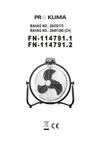
Black and white photo of a 49-degree front-mounted air fan with visible blades and control panel (no text or symbols)Inhalt – Съдържание – Sadržaj – Obsah – Indhold – Contenido – Sisukord – Sisältö – Contenu – Content – Sadržaj – Tartalom – Innihald – Contenuto – Inhoud – Innhold – Sadržaj – Obsah – Vsebina – Innehåll – İçerik
Bedienungsanleitung – German....- 2 -
Ръководство с инструкции – Bulgarian...... - 8 -
Uputstvo – Bosnian ...... - 14 -
Návod k použití – Czech ...... - 19 -
Brugsanvisning – Danish....- 24 -
Manual de Instrucciones – Spanish....- 29 -
Kasutusjuhend – Estonian ....- 34 -
Käyttöopas – Finnish ...... - 39 -
Mode d'emploi – French ...... - 44 -
Instruction manual – English....- 50 -
Upute za rad – Croatian ....- 55 -
Használati útmutató – Hungarian ...... - 60 -
Leiðbeiningarhandbók – Icelandic.... - 66 -
Manuale d'istruzioni – Italian....- 71 -
Gebruiksaanwijzing – Dutch....- 77 -
Brukermanual – Norwegian ...... - 83 -
Uputstvo – Serbian-Latin....- 88 -
Návod na obsluhu – Slovakian ....- 93 -
Priročnik za uporabo – Slovenian....- 98 -
Bruksanvisning – Swedish ...... - 103 -
Kullanım talimatı – Turkish...... - 108 -
GEBRAUCHSANWEISUNG
MONTAGEANLEITUNGEN
Abb. 2
Betrieb
Фиг. 1
Фиг. 2
РАБОТА
UPUTSTVA ZA SASTAVLJANJE
sl. 1
sl. 2
RAD
NÁVOD K SESTAVENÍ
Obr. 1
Obr. 2
OBSLUHA
VEJLEDNINGER TIL SAMLING
Fig. 1

Fig. 2
BETJENING
- Slut ledningen til en passende stikkontakt.
- Ventilatoren tæ ndes med styrkeknappen på betjeningspanelet: SLUK (OFF) = Sluk, LAV (LOW) = Lav hastighed, MED (MED) = Mellemhastighed, H∅ J (HIGH) = Høj hastighed.
-
DREJNING (SWING): Tryk på denne knap, hvis ventilatoren skal dreje fra side til side.
-
Hæ Idningsvinkler: Sluk for ventilatoren, og tryk eller træ k derefter i ringbeslaget, for at justere hæ ldningen på luftstrømmen.
RENG∅ RING
INSTRUCCIONES DE ENSAMBLAJE
Img. 2
FUNCIONAMIENTO
Joon. 1
Joon. 2
KASUTAMINE
Kuva 1
Kuva 2
KÄYTTÄMINEN
INSTRUCTIONS D'ASSEMBLAGE
Schéma 2
FONCTIONNEMENT
Please read these Operating Instructions through carefully before connecting your appliance to the mains, in order to avoid damage due to incorrect use. Please pay particular attention to the safety information. If you pass the appliance on to a third party, these Operating Instructions must also be handed over.
WARNING – When using electrical appliance, basic safety precautions should always be followed to reduce the risk of fire, electrical shock and personal injury.
SAFETY INFORMATION
- Read and save these instructions. Attention: pictures in the IM are for reference only.
- This appliance can be used by children aged from 8 years and above and persons with reduced physical, sensory or mental capabilities or lack of experience and knowledge if they have been given supervision or instruction concerning use of the appliance in a safe way and understand the hazards involved.
- Children shall not play with the appliance.
- Cleaning and user maintenance shall not be made by children without supervision.
- If the supply cord is damaged, it must be replaced by the manufacturer, its service agent or similarly qualified persons in order to avoid a hazard.
- This appliance is intended to be used in household and similar applications.
- Incorrect operation and improper handling can lead to faults on the appliance and injuries to the user.
- In the event of improper use or incorrect handling, no liability can be accepted for any damage that may occur.
-
Do not immerse the unit or mains plug in water or other liquids. There is danger to life due to electric shock! However, if this occurs, remove the mains plug immediately and then have the unit checked by an expert before using it again.
-
Do not operate the appliance if the mains cable or the mains plug show signs of damage, if the appliance has fallen on the floor or has been otherwise damaged. In such cases take the appliance to a specialist for checking and repair if necessary.
- Never remove the mains plug from the socket by pulling on the mains cable, or with wet hands.
- Ensure that the mains cable does not hang over sharp edges or allow it to become trapped.
- Keep the appliance away from damp, and protect from splashes.
- Keep the appliance away from hot objects (e.g. hotplates) and open flames.
- Keep the appliance and its cord out of reach of children less than 8 years.
- Use the appliance on a flat, dry and heat resistance surface.
- Never leave the appliance unattended during use.
- Do not store or operate the appliance in the open air.
- Keep the appliance in a dry place, inaccessible to children (in its packaging).
- Never put fingers or any other objects through the grilles (fan guards) when the fan is running.
- Never operate the product without the fan guards in place, as serious personal injury may result.
- The appliance must be assembled completely before use.
- Watch out for long hair! It can be caught in the fan owing to the air turbulence.
- Do not point the air flow to the people for a long time.
- Ensure that the fan is switched off from the supply mains before removing the guard.
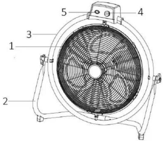
PARTS DESCRIPTION
- Main body (Fan guard + Fan blade)
- Stand base
- Circular bracket
- Speed switch
- Swing button
ASSEMBLY INSTRUCTIONS
** Please assemble correctly by the following order when using.
- Assemble the stand base.
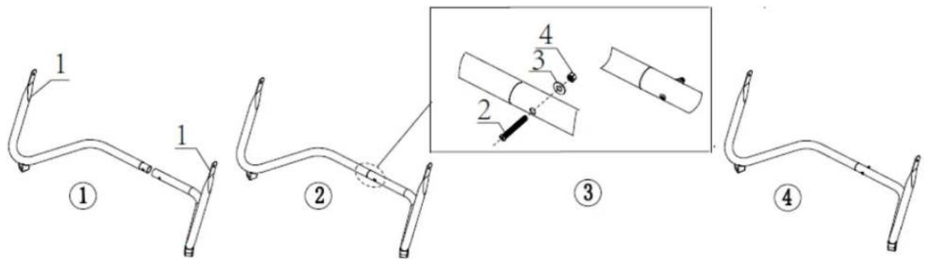
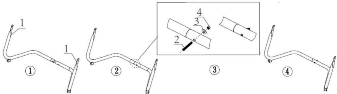
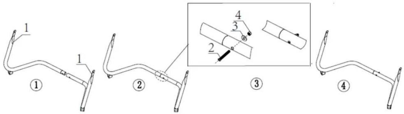
Attach the right and left support brackets (1) together, and fix them by screw (2), washer (3) and nut (4). (Fig.1)
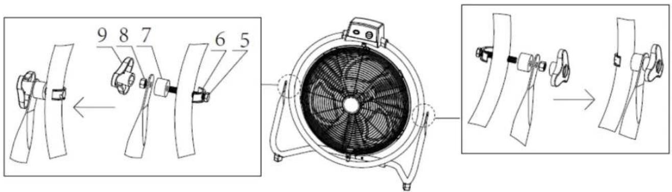
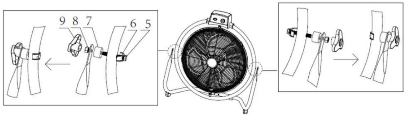
- Assemble the fan head to the stand base.
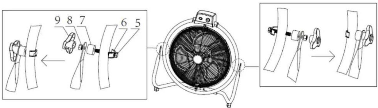
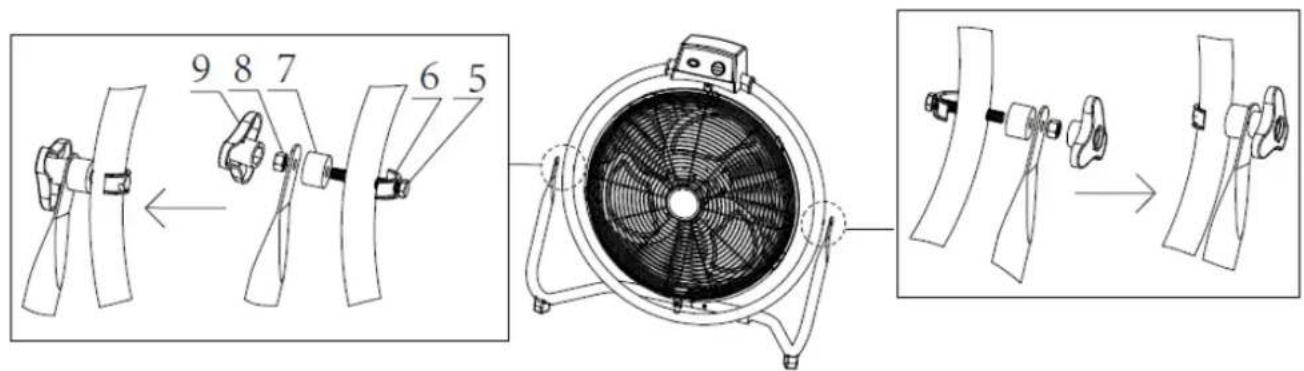
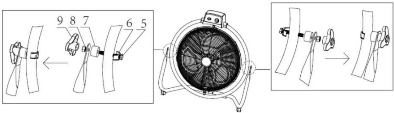
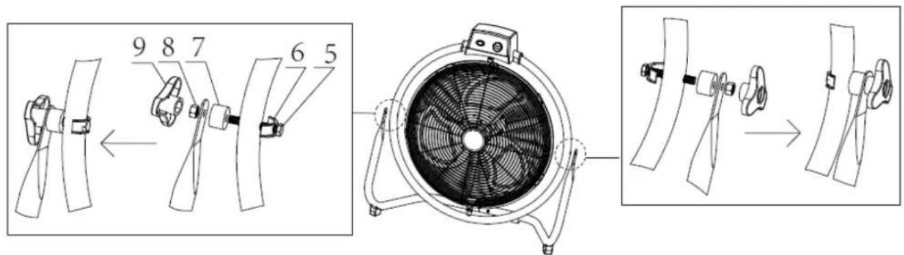
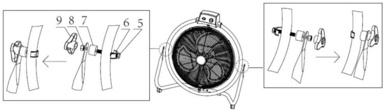
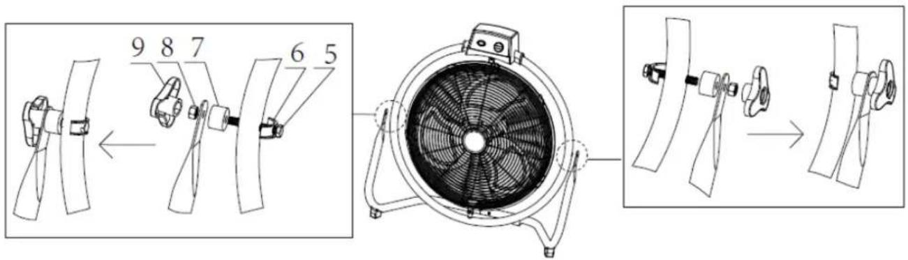
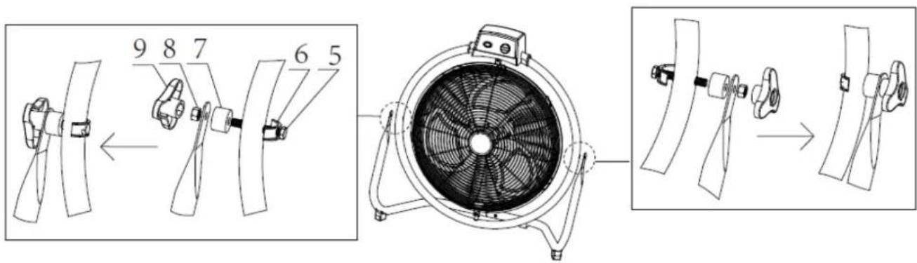
Find the screw hole in the left side of the circular bracket. Fix the circular bracket and the left support bracket by long screw (5), U-type stator (6), article shockproof (7) and nut (8). You can twist the nut easily using the nut holder (9). Please follow the installation order in Fig.2.
Assemble the right side in the same order.
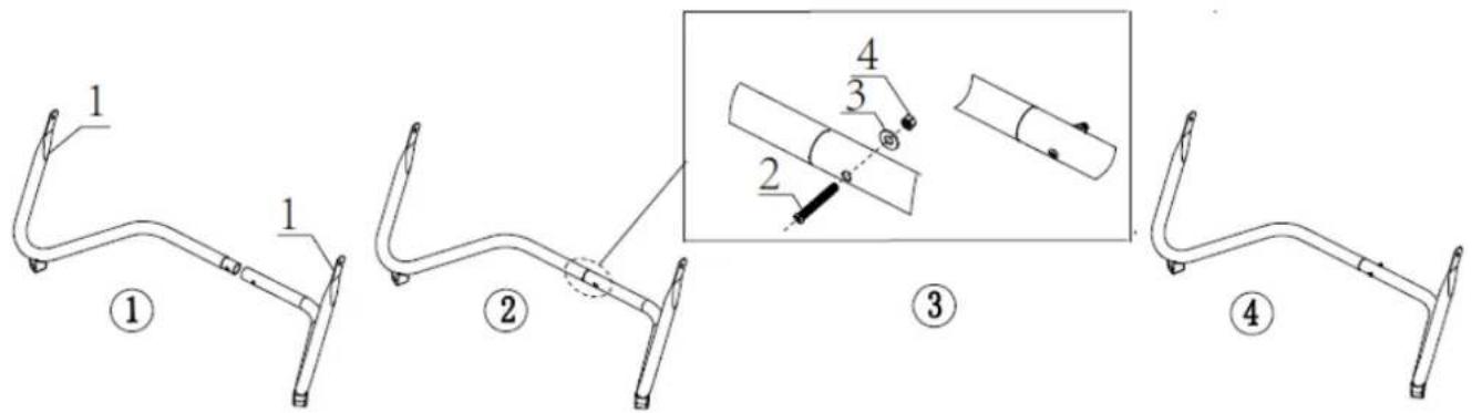
Fig. 1
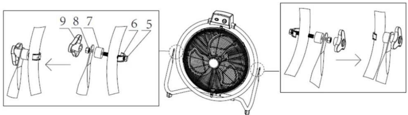
Fig. 2
OPERATION
- Plug the power cord into a suitable socket.
- The fan is switched on by using the speed buttons on the control box: OFF = off, LOW = Low speed, MED = Medium speed, HIGH = High speed.
- SWING: Press this button to control the oscillation function on and off.
- Tilting Angles: turn off the fan, then push or pull the circular bracket to adjust the angle of airflow.
CLEANING
- Before servicing the fan and after each occasion of use, switch off the appliance and unplug the mains cable from the socket.
- Never immerse the appliance in water (danger of short-circuit). To clean the appliance, only wipe it down with a damp cloth and dry it carefully. Always take out the mains plug first.
- Take care that excessive dust does not build up in the air-intake and air-outlet grille, and clean it occasionally using a dry brush or vacuum cleaner.
TECHNICAL DATA
Operating voltage: 220-240V \~ 50/60Hz
Power consumption: 120W
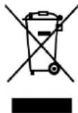
Recycling – European Directive 2012/19/EU
This marking indicates that this product should not be disposed with other household wastes. To prevent possible harm to the environment or human health from uncontrolled waste disposal, recycle it responsibly to promote the sustainable reuse of material resources. To return your used device,
please use the return and collection systems or contact the retailer where the product was purchased. They can take this product for environmental safe recycling.
ERP information (GB)
Supplier: BAHAG AG
Gutenbergstr. 21
68167 Mannheim
Germany
Declare that the product detailed below:
Information requirements
| Information to identify the FN-114791.1& FN-114791.2 to which the information relates to [High velocity fan] | |||
| Description | Symbol | Value | Unit |
| Maximum fan flow rate | F | 122,94 | m^3/min |
| Fan power input | P | 117,5 | W |
| Service value | SV | 1,05 | (m^3/min)/W |
| Standby power consumption | P_SB | - | W |
| Fan sound power level | LWA | 65,54 | dB(A) |
| Maximum air velocity | c | 4,59 | meters/sec |
| Measurement standard for service value | IEC 60879:1986 (corr.1992) | ||
| Contact details for obtaining more information | BAHAG AGGutenbergstr. 2168167 MannheimGermany | ||
Satisfies the requirement of the Council Directives:
COMMISSION REGULATION (EU) No 206/2012 of 6 March 2012 and Amending COMMISSION REGULATION (EU) 2016/2282 implementing Directive 2009/125/EC of the European Parliament and of the Council with regard to ecodesign requirements for air conditioners and comfort fans
Regarding information for consumers on how to install, use and maintain the product, WEEE information, please check the instruction manual provided with packaging.
UPUTE ZA UPOTREBU
UPUTE ZA SKLAPANJE
**Montirajte propisanim redom pri upotrebi.
• Montaža postolja stalka.
Pričvrstite međusobno desni i lijevi nosač (1) i pričvrstite ih vijkom (2), podloškom (3) i maticom (4). (Sl.1)
- Montirajte glavu ventilatora na postolje stalka.
Pronadite rupu za vijak na lijevoj strani kružnog nosača. Pričvrstite kružni nosač i lijevi nosač dugačkim vijkom (5), statorom U-tipa (6), dio za zaštitu od udarca (7) i maticu (8). Maticu možete lako okretati s pomoću držača matice (9). Slijedite redoslijed montaže na SI. 2.
Na isti način montirajte desnu stranu.
Sl. 1
Sl. 2
RAD
- ábra
- ábra
HASZNÁLAT
Mynd 1
Mynd 2
NOTKUN
ASSEMBLAGGIO
Fig. 1

Fig. 2
FUNZIONAMENTO
IN ELKAAR ZETTEN
Afb. 1
Afb. 2
WERKING
MONTERINGSANVISNING
Fig. 1
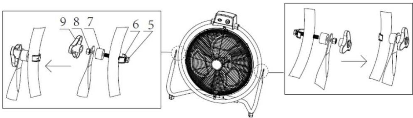
Fig. 2
BETJENING
UPUTSTVA ZA SASTAVLJANJE
sl. 2
RAD
NÁVOD NA MONTÁŽ
Obr. 2
OBSLUHA
NAVODILA ZA SESTAVLJANJE
Slika 2
DELOVANJE
- Vtič priključite v primerno vtičnico.
-
Ventilator vklopite z zasukom gumbov za hitrost na krmilni omarici: OFF = IZKLOP, LOW = nizka hitrost, MED = srednja hitrost, HIGH = visoka hitrost.
-
NIHANJE (SWING): S pomočjo tega gumba izklopite in vklopite funkcijo nihanja.
- Koti nagiba: izklopite ventilator, nato potisnite ali povlecite okroglo stojalo, da nastavite kot pretoka zraka.
ČIŠČENJE
MONTERINGSINSTRUKTIONER
Bild 1
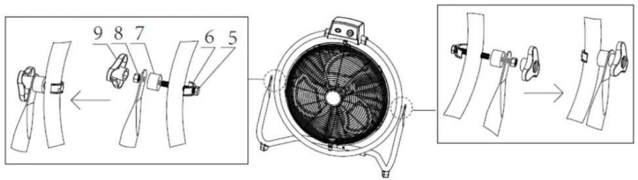
Bild 2
ANVÄNDNING
KURULUM TALİMATLARI
Şek. 2
ÇALIŞMA

- GEBRAUCHSANWEISUNG
- MONTAGEANLEITUNGEN
- Betrieb
- РАБОТА
- UPUTSTVA ZA SASTAVLJANJE
- RAD
- NÁVOD K SESTAVENÍ
- OBSLUHA
- VEJLEDNINGER TIL SAMLING
- BETJENING
- RENG∅ RING
- INSTRUCCIONES DE ENSAMBLAJE
- FUNCIONAMIENTO
- KASUTAMINE
- KÄYTTÄMINEN
- INSTRUCTIONS D'ASSEMBLAGE
- FONCTIONNEMENT
- SAFETY INFORMATION
- PARTS DESCRIPTION
- ASSEMBLY INSTRUCTIONS
- OPERATION
- CLEANING
- TECHNICAL DATA
- ERP information (GB)
- UPUTE ZA UPOTREBU
- UPUTE ZA SKLAPANJE
- HASZNÁLAT
- NOTKUN
- ASSEMBLAGGIO
- FUNZIONAMENTO
- IN ELKAAR ZETTEN
- WERKING
- MONTERINGSANVISNING
- NÁVOD NA MONTÁŽ
- NAVODILA ZA SESTAVLJANJE
- DELOVANJE
- ČIŠČENJE
- MONTERINGSINSTRUKTIONER
- ANVÄNDNING
- KURULUM TALİMATLARI
- ÇALIŞMA
Brand : Emerio
Model : FN114791
Category : Fan