
BalancedForce 210 - Subwoofer Martin Logan - Free user manual and instructions
Find the device manual for free BalancedForce 210 Martin Logan in PDF.


| Product Type | Active Subwoofer |
| Brand | Martin Logan |
| Model | BalancedForce 210 |
| Frequency Response | 20–120 Hz ±3 dB (LFE input) |
| Amplifier | 850 W RMS (1700 W peak), Class D |
| Speaker Configuration | Dual 10-inch (25.4 cm) in BalancedForce configuration |
| Low-Pass Filter | 30–80 Hz adjustable, with custom filter option |
| Phase Adjustment | 0°, 90°, 180°, 270° |
| 25 Hz Level Control | -10 dB to +10 dB |
| Inputs | RCA (L/R, LFE), XLR (L/R, LFE), speaker (banana plugs), 12V trigger (3.5 mm) |
| Outputs | Multi Out RCA for daisy-chaining |
| USB Ports | USB for updates and custom filters, mini USB for PBK |
| Power Consumption | 125 W typical, 15 W standby |
| Power Supply | AC, voltage according to country of purchase |
| Dimensions (H x W x D) | 48.3 x 48.6 x 49.4 cm (19 x 19.1 x 19.4 inches) |
| Weight | 43.5 kg (96 lb) |
| Special Features | BalancedForce, PBK (Perfect Bass Kit) optional, tone sweep, room correction |
| Cleaning | Soft cloth or microfiber brush |
| Safety | Overload protection, mandatory grounding, unplug before storm |
Frequently Asked Questions - BalancedForce 210 Martin Logan
User questions about BalancedForce 210 Martin Logan
0 question about this device. Answer the ones you know or ask your own.
Ask a new question about this device
Download the instructions for your Subwoofer in PDF format for free! Find your manual BalancedForce 210 - Martin Logan and take your electronic device back in hand. On this page are published all the documents necessary for the use of your device. BalancedForce 210 by Martin Logan.
USER MANUAL BalancedForce 210 Martin Logan
BALANCED FORCE™ [210]
BALANCED FORCE™ [212]
user's manual
natural_image
Line drawing of a square box with a rectangular lid and a small rectangular base, no text or symbols present.
IMPORTANT SAFETY INSTRUCTIONS
1 Read Instructions – All the safety and operating instructions should be read before the product is operated.
2 Retain Instructions – The safety and operating instructions should be retained for future reference.
3 Heed Warnings – All warnings on the product and in the operating instructions should be adhered to.
4 Follow Instructions – All operating and use instructions should be followed.
5 Cleaning — Unplug this product from the wall outlet before cleaning. Do not use liquid cleaners or aerosol cleaners. Use a damp, soft cloth for cleaning.
6 Water and Moisture — Do not use this product near water—for example, near a bath tub, wash bowl, kitchen sink, or laundry tub; in a wet basement; or near a swimming pool; and the like.
7 Accessories — Do not place this product on an unstable cart, stand, tripod, bracket or table. The product may fall, causing serious injury to a child or adult, and serious damage to the product. Use only with a cart, stand, tripod, bracket or table recommended by the manufacturer, or sold with the product. Any mounting of the product should follow manufacturer's instructions and should use a mounting accessory recommended by the manufacturer.

8 Ventilation — Slats and openings in the cabinet are provided for ventilation and to ensure reliable operation of the product and to protect it from overheating, and these openings must not be blocked or covered. The openings should never be blocked by placing the product on a bed, sofa, rug, or other similar surface. This product should not be placed in a built-in installation such as a bookcase or rack unless proper ventilation is provided or the manufacturer's instructions have been adhered to.
9 Power Sources — This product should be operated only from the type of power source indicated on the marking label. If you are not sure of the type of power supply to your home, consult your product dealer or local power company. For products intended to operate from battery power, or other sources, refer to the operating instructions.
10 Grounding and Polarization - This product may be equipped with a polarized alternating-current line plug (a plug having one blade wider than the other). This plug will fit into the power outlet only one way. This is a safety feature. If you are unable to insert the plug fully into the outlet, try reversing the plug. If the plug should still fail to fit, contact your electrician to replace your obsolete outlet. Do not defeat the safety purpose of the polarized plug.
11 Power-Cord Protection - Power supply cords should be routed so that they are not likely to be walked on or pinched by items placed upon or against them, paying particular attention to cords at plugs, convenience receptacles, and the point where they exit from the product.
12 Lightning - For added protection for this product during a lightning storm, or when it is left unattended and unused for long periods of time, unplug it from the wall outlet and disconnect the antenna or cable systems. This will prevent damage to the product due to lightning and power-line surges. 13 Overloading - Do not overload wall outlets, extension cords, or integral convenience receptacles as this can result in a risk of fire or electric shock.
14 Object and Liquid Entry — Never push objects of any kind into this product through openings as they may touch dangerous voltage points or short-out parts that could result in a fire or electric shock. Do not expose this apparatus to dripping or splashing, and ensure that no objects filled with water, such as vases, are placed on the apparatus.
15 Servicing — Do not attempt to service this product yourself as opening or removing covers may expose you to dangerous voltage or other hazards. Refer all servicing to qualified service personnel.
16 Damage Requiring Service — Unplug this product from wall outlet and refer servicing to qualified personnel under the following conditions:
- When power supply cord or plug is damaged;
• If liquid has been spilled, or objects have fallen into product;
• If the product has been exposed to rain or water;
- If the product does not operate normally by following the operating instructions. Adjust only those controls that are covered by the operating instructions as an improper adjustment of other controls may result in damage and will require extensive work by a qualified technician to restore the product to its normal operation;
- If the product has been dropped or damaged in any way;
- If the product exhibits a distinct change in performance—this indicates a need for service.
17 Replacement Parts — When replacement parts are required, be sure the technician has used replacement parts specified by the manufacturer or have the same characteristics as the original part. Unauthorized substitutions may result in fire, electric shock, or other hazards.
18 Safety Check — Upon completion of any service or repairs to this product, ask the service technician to perform safety checks to determine that the product is in proper operating condition.
19 Wall or Ceiling Mounting – The product should be mounted to a wall or ceiling only as recommended by the manufacturer.
20 Heat - The product should be situated away from heat sources such as radiators, heat registers, stoves, or other products (including amplifiers) that produce heat.
NOTE: This equipment has been tested and found to comply with the limits for a Class B digital device, pursuant to part 1.5 of the FCC Rules. These limits are designed to provide reasonable protection against harmful interference in a residential installation. This equipment generates uses and can radiate radio frequency energy and, if not installed and used in accordance with the instructions, may cause harmful interference to radio communications. However, there is no guarantee that interference will not occur in a particular installation. If this equipment does cause harmful interference to radio or television reception, which can be determined by turning the equipment off and on, the user is encouraged to try to correct the interference by one or more of the following measures:
— Reorient or relocate the receiving antenna.
— Increase the separation between the equipment and receiver.
— Connect the equipment into an outlet on a circuit different from that to which the receiver is connected.
— Consult the dealer or an experienced radio/TV technician for help.
Thank you—the MartinLogan owner, for loving what we do, and making it possible for us to do what we love.
natural_image
Isometric line drawing of a layered mechanical or architectural structure with no visible text or symbolsnatural_image
Technical line drawings of electronic components including a flat panel, coiled cable, and four threaded pins (no text or symbols present)Serial Numbers: ____ Record your serial numbers here for easy reference. You will need this information when filling out your warranty registration. Your serial number is located near the bottom of the backplate and on the shipping container.
Settings:
Level:
25Hz Level:
Low-Pass Filter:
Phase: Custom Low-Pass Filter Loaded:
A/V Processor Bass Management Settings:
Main Speaker Size: ____ (large recommended for full range speakers)
Center Speaker Size: ____ (small recommended)
Surround Speaker Size: ____ (small recommended)
Level:
High-Pass:
Low-Pass:
Numéro de série

In accordance with the European Union WEEE (Waste Electrical and Electronic Equipment) directive effective August 13, 2005, we would like to notify you that this product may contain regulated materials which upon disposal, according to the WEEE directive, require special reuse and recycling processing.
For this reason MartinLogan has arranged with our distributors in European Union member nations to collect and recycle this product at no cost to you. To find your local distributor please contact the dealer from whom you purchased this product, email info@martinlogan.com or visit the distributor locator at www.martinlogan.com.
Please note, only this product itself falls under the WEEE directive. When disposing of packaging and other related shipping materials we encourage you to recycle these items through the normal channels.

The exclamation point within an equilateral triangle is intended to alert the user to the presence of important operating and maintenance (servicing) instructions in the literature accompanying the appliance.

The lightning bolt flash with arrowhead symbol, within an equilateral triangle, is intended to alert the user to the presence of uninsulated "dangerous voltage" within the product's enclosure that may be of sufficient magnitude to constitute a risk of electric shock.

WARNING! Do not use your subwoofer outside of the country of original sale—voltage requirements vary by country. Improper voltage can cause damage that will be potentially expensive to repair. The subwoofer is shipped to MartinLogan authorized distributors with the correct power supply for use in the country of intended sale. A list of authorized distributors can be accessed at www.martinlogan.com or by emailing info@martinlogan.com.

BalancedForce 210 & Balanced Force 212
Tested to Comply with FCC Standards FOR HOME OR OFFICE USE

BalancedForce 210 & Balanced Force 212
This device complies with part 15 of the FCC Rules. Operation is subject to the following two conditions: (1) This device may not cause harmful interference, and (2) this device must accept any interference received, including interference that may cause undesired operation.
• Hazardous voltages exist inside—do not remove cover.
• Refer servicing to a qualified technician.
- To prevent fire or shock hazard, do not expose this module to moisture.
- Turn amplifier off and unplug subwoofer should any abnormal conditions occur.
- The power cord should not be installed, removed, or left detached from the speaker while the other end is connected to an AC power source.
- The main power switch near the AC inlet shall remain readily operable.
• Use only with a grounded electrical outlet.
- No candles or other sources of open flame should be placed on the speaker.
- No liquids either in glasses or vases should be placed on speaker.
- Speaker should not be exposed to dripping or splashing liquids.
- The terminals marked with the lightning bolt symbol should be connected by an instructed person or by way of ready made terminals.
- The power cord should remain readily operable should any abnormal conditions occur.
We know you are eager to hear your new MartinLogan subwoofer, so this section is provided to allow fast and easy set up. Once you have your subwoofer operational, please take the time to read, in depth, the rest of the information in the enclosed manual. It will give you perspective on how to attain the greatest possible performance from this most exacting woofer system.
If you should experience any difficulties in the setup or operation of your MartinLogan subwoofer, please refer to the Room Acoustics, Placement or Operation sections of the enclosed owner's manual. Should you encounter a persistent problem that cannot be resolved, please contact your authorized MartinLogan dealer. They will provide you with the appropriate technical analysis to alleviate the situation.
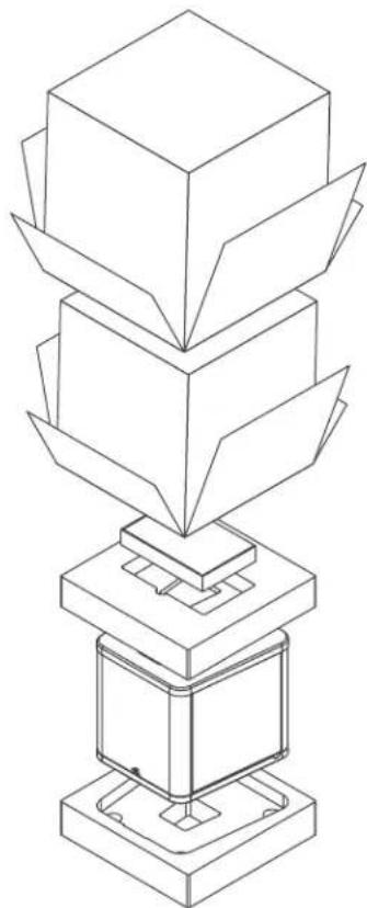
Step 1: Unpacking
Remove your new subwoofer from its packing. Please retain the original packing materials for future use—replacement packaging may be expensive.
Step 2: Placement
You may choose to begin by placing the subwoofer in a corner near the front of the room. If placed in a corner, align the subwoofer diagonally so both woofers are equidistant from the adjacent wall. Before deciding on a permanent corner placement, experiment with other positions. Locations away from corners often prove more effective in providing ideal low-frequency performance and blend with the main speakers. Please see the Placement section for details.
Step 3: Signal Connection
Use the best cables you can. High quality cables, available from your specialty dealer, are recommended and will give you superior performance.
Attach your preamplifier/processor outputs to the signal input connectors located on the subwoofer's rear panel. Please see the Controls and Connections section for details.
If you plan to connect your subwoofer using Speaker Level (high level) inputs, refer to the Speaker Level Inputs section for details.
Step 4: Power Connection (AC) (see warning)
Make sure the level knob is set at 0. Plug the subwoofer into a wall outlet. Review the AC Power Connection section of this manual for details.
Step 5: Setting the Controls
- Set the Level knob to 3 or 4.
- Set the Mode switch to 'Auto (Trigger)'.
- Set the 25Hz level knob to 0.
- Set the Phase knob to 90^ .
- Set the Low Pass Filter knob to a setting lower than the low-end frequency response of your main speakers. If you are uncertain of your main speaker low-frequency response, start with a setting of 35Hz.
Step 6: Listen and Enjoy.

natural_image
Warning symbol with exclamation mark inside triangle (no text or numbers)

natural_image
Warning symbol with exclamation mark inside triangle (no text or numbers)
natural_image
Warning symbol with exclamation mark inside triangle against black vertical background (no text or numbers)
natural_image
Black vertical bar with a triangular warning symbol (inverted triangle) and an exclamation mark at the top (no text or numbers present)Accessing the Control Panel 18
Top Control Panel 18
Connections 20
Rear Connection Panel....20
Break-In. 21
AC Power Connection 21
2-Channel Mode (Line Level RCA or Balanced XLR) ..... 22
Multi-Channel Mode 24
Simultaneous 2-Channel/Multi-Channel Mode ..... 26
Using Speaker Level Inputs 28
Advanced Setup.... 29
Loading a Custom Low-Pass Filter 29
Updating Firmware 29
PBK Room Correction....30
Multi Out—Daisy Chaining Multiple Subwoofers.....30
Optional Wireless Connection....31
Placement 32
Subwoofer Placement 32
Installing in a Cabinet 33
Ask Your Dealer 33
Solid Footing 33
Enjoy Yourself. 33
Room Acoustics 34
Your Room....34
Terminology 34
Home Theater 35
MartinLogan Exclusives 36
BalancedForce™ For Cleaner Bass. 36
Proprietary Switching Amplifiers 36
25Hz Level Control 36
PBK (Perfect Bass Kit) 36
Optional Custom Low-Pass Filters 36
Frequently Asked Questions.... 37
Troubleshooting 37
General Information 38
Warranty and Registration 38
Serial Number 38
Service 38
Specifications. 39
Glossary of Audio Terms 40
Dimensional Drawings 71
BalancedForce 210 71
BalancedForce 212 72
Congratulations! You have invested in one of the world's premier subwoofers.
MartinLogan BalancedForce 210 and 212 subwoofers represent the culmination of an intensive, dedicated research program directed toward creating a world class reference subwoofer design using advanced technologies without compromising durability, reliability, craftsmanship or aesthetics.
These subwoofers use dual, custom, high-excision drivers in a BalancedForce™ configuration which dramatically reduces cabinet vibrations allowing deep, tight, well-defined bass. Powerful, proprietary amplifiers drive the output stage with precision and extremely high efficiency. Low-pass filtering and phase control have been designed to make integrating the subwoofers with both MartinLogan and non-MartinLogan products seamless and simple. Model specific custom low-pass filters allow these subwoofers to integrate precisely with MartinLogan main speakers.
Additionally, PBK ^™ (Perfect Bass Kit) room correction technology (sold separately) measures the subwoofer's acoustic output within a room and optimizes performance to compensate for the unique (and sometimes challenging) characteristics of a listening environment.
The materials in your new subwoofer are of the highest quality and will provide years of enduring enjoyment. The cabinetry is constructed from the highest quality wood, composite, and aluminum materials for acoustic integrity.
This User's Manual will explain in detail the operation of your subwoofer and the philosophy applied to its design. A clear understanding will help you obtain maximum performance and pleasure from this high performance subwoofer system.
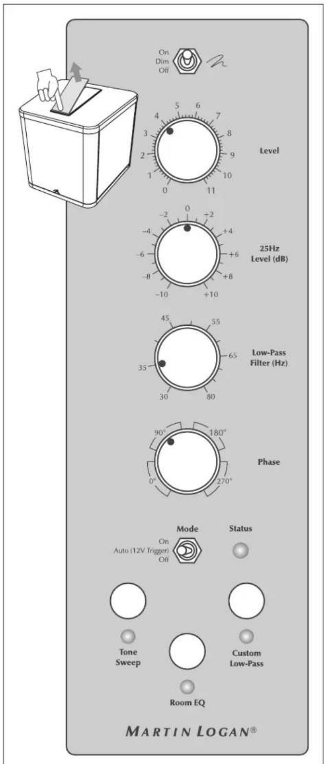
Figure 1. Top control panel. Press down on front edge of glass to access.
Accessing the Control Panel
The control panel is hidden beneath the glass located on top of the subwoofer. To access the control panel, gently press down on the front edge of the glass. The opposite edge of the glass will tilt up and allow for easy removal.
Top Control Panel
On/Off/Dim
This switch controls the brightness of the blue accent light on top of your subwoofer.
Level
Setting the level too high will cause the bass to seem bloated and is the most common cause of bad sounding subwoofers. A rule of thumb is that the subwoofer's bass should not draw attention to itself. Instead it should simply make the system's low end seem more extended and accurate.
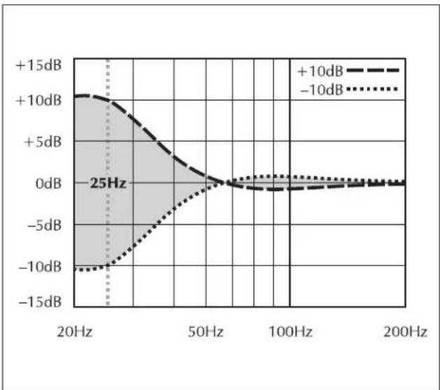
25Hz Level (dB)
The 25Hz Level knob significantly adjusts a frequency where peaks and dips of different amplitudes often develop. The ideal setting is dependent on room size and construction, system configuration and personal preference. This knob's setting is ignored when PBK setup is running. If you use PBK auto room correction we recommend first listening with this knob set to 0 after PBK has been run (you can use this knob later to add or subtract low-end extension as needed).
line
| Frequency | +10dB (dB) | -10dB (dB) | | --------- | ---------- | ---------- | | 20Hz | +10dB | -10dB | | 50Hz | 0dB | 0dB | | 100Hz | 0dB | 0dB | | 200Hz | 0dB | 0dB |Figure 2. Frequencies affected by the 25Hz Level control
Low-Pass Filter (Hz)
The Low-Pass Filter knob allows you to adjust the low-pass frequency for the left and right inputs (RCA, XLR, or speaker level inputs). This knob is not applied to the LFE (RCA or XLR) inputs, instead leaving the task of bass management to your audio/video processor.
As a general rule, the Low-Pass Filter should be set at the option approximately equal to (or below) 70% of your main speaker's lowest frequency response. For example, your speaker's frequency response goes down to 43Hz. 70% of 43Hz equals 30.1, so you should set the subwoofer's low pass filter to 30Hz. We advise that once you try the recommended setting using the formula above, you should try the surrounding settings as well. If you are uncertain of your main speaker low-frequency response, start with a setting of 35Hz. You will not harm anything by experimenting with different settings.
Please note, the settings on this knob are bypassed altogether if the "Custom Low-Pass" button is engaged. Custom Low-Pass filters are discussed later in this manual.
Phase Control
The Phase control is entirely dependent on numerous factors including the size and configuration of your listening environment, the placement of the unit, and seating arrangement. Due to the way bass sound waves develop in different rooms there is no rule of thumb for setting phase. For instance, if your room has a peak at the subwoofer crossover area, you may wish to set the phase so the actual acoustic outputs of the subwoofer and main speakers are out of phase. Experiment and try different settings and be patient.
If you are using the subwoofer to augment other MartinLogan products, we suggest starting with the phase set at 90°. If you are using a Custom Low-Pass filter, we suggest you start with the Phase set at 0°. Custom Low-Pass filters provided for these subwoofers are already phase optimized.
In a system where phase is properly set, the main speakers and subwoofer should work together and sound as if there is more total bass in the system. If your main speakers and subwoofer are out-of phase their sound waves will cancel each other and total bass output in the system will sound decreased. Again, experiment and listen for the smoothest bass without any prominent or absent notes.
Mode
The 'On/Auto [Trigger]/Off' switch controls the subwoofer's energy saving feature. The 'On' setting prevents the sub from entering energy saving mode. When set to 'Auto (Trigger)', the sub will turn on when a music signal is detected and off after several minutes without a signal. If a 12-volt trigger is connected, the triggering device will turn the subwoofer on and off. When the 'Off' setting is selected the subwoofer will not operate.
Status Light
Your subwoofer is equipped with a multi-color LED to indicate its current status. This light is identical in function to the Power Status light on the subwoofer's back panel. The following list explains the meaning of the different colors:
No color: No power. The subwoofer is not plugged in or has shutdown due to an overload condition. Unplug the subwoofer and plug it back in to correct.
Green: Play mode. This indicates the subwoofer detects an audio signal and has automatically switched into play mode.
Red: Standby. This indicates your subwoofer has switched into a power saving mode.
Tone Sweep
Holding this button for 1-second initiates a tone sweep from 120Hz–20Hz. A second press pauses the tone sweep and holds the current frequency. A third press stops the tone sweep. This feature is useful for locating areas in your listening room where troublesome rattles or resonances may occur. The tone sweep feature may also prove useful when setting phase, crossover, and volume on the subwoofer.
Room EQ
This button allows you to toggle room correction on and off. If the LED below this button is lit the configuration from the PBK room correction system is being used. If the LED is off the room correction is not being used. If you press the button and the LED flashes for 10-seconds your subwoofer has not been configured using the PBK system. PBK (Perfect Bass Kit) room correction is discussed later in this manual.
Custom Low-Pass
This button allows you to toggle an optional custom low-pass filter on and off. If the LED below this button is lit your subwoofer is using a custom low-pass filter. Please note, when this feature is engaged it overrides the Low-Pass Filter knob. If the LED is off, your subwoofer is not using a custom low-pass filter and your subwoofer will instead use the Low-Pass Filter knob. If you press the button and the LED flashes for 10-seconds your subwoofer has not been loaded with a custom low-pass filter. Custom low-pass filters are discussed later in this manual.
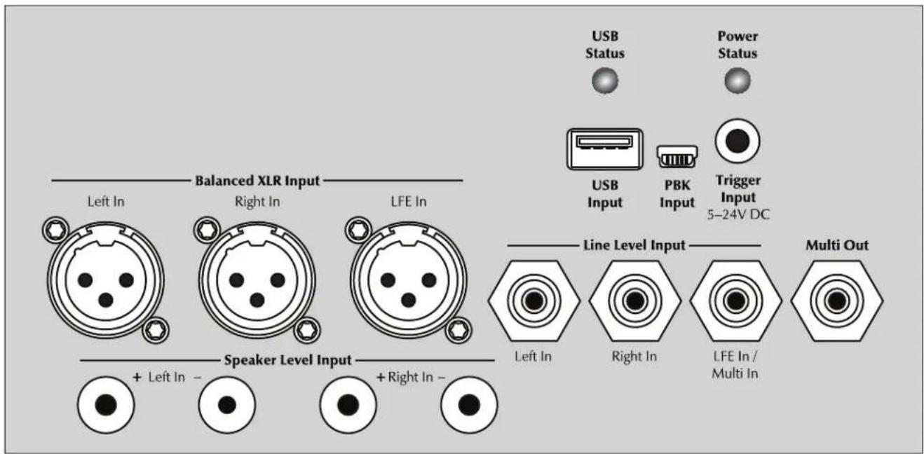
Figure 3. Rear connection panel
Rear Connection Panel
USB Status Light (with Flash Drive Connected)
When connecting a USB flash drive to the USB Input the light indicates the following statuses:
No color: Idle (no USB device currently connected).
Flashing Green: Reading USB flash drive.
Solid Green: Success. File found and loaded. Okay to remove USB flash drive.
Solid Red: Failed. Cannot find file or flash drive not formatted using FAT32 file system.
Flashing Red: Failed. Cannot read drive due to electrical problem.
USB Status Light (with PBK Connected)
When connecting a computer via mini-USB to the PBK Input, the light indicates the following statuses:
No color: Idle (no USB device currently connected).
Solid Green: Computer connection okay.
Solid Red: Computer connection problem.
Power Status Light
Your subwoofer is equipped with a multi-color LED to indicate the current status of the subwoofer. This light is identical in function to the Status light on the subwoofer's top panel. The following list explains the meaning of the different colors:
No color: No power. The subwoofer is not plugged in or has shutdown due to an overload condition. Unplug the subwoofer and plug it back in to correct.
Green: Play mode. This indicates the subwoofer detects an audio signal and has automatically switched into play mode.
Red: Standby. Your sub has switched into power saving mode.
USB Input
This input allows you to connect a standard USB flash drive and upload a custom low-pass filter or update the subwoofer's firmware. Custom low-pass filters and firmware updates are discussed later in this manual. Please note, the PBK Input and USB Input should never be used at the same time.
PBK Input
This input allows you to connect the optional PBK (Perfect Bass Kit) room correction system via a mini-USB cable. PBK is discussed later in this manual. Please note, the PBK Input and USB Input should never be used at the same time.
Trigger Input (5V-24V DC)
If you have an external source component (such as a processor or a receiver) with built in trigger controls, you may wish to turn the subwoofer on and off with this source. Connect a cable from the control component to this input and set the Mode switch on the top panel to 'Auto (Trigger)'. Although this technology is commonly referred to as a 12V trigger, your subwoofer will respond to any signal between 5–24V DC (3.5mm connector tip positive).
Left In / Right In (Balanced XLR)
Connect from the Main-Out or Pre-Out (or Sub-Out) on your receiver/pre-amp. The setting for the Low-Pass Filter control is applied to the signal received through these inputs.
LFE In (Balanced XLR)
Connect from the LFE Out (or Sub Out) on your A/V processor. The setting for the Low-Pass Filler control is not applied to this connection. Crossover settings for LFE In are controlled through your A/V processor.
Left In / Right In (Line Level)
Connect from the Main-Out or Pre-Out (or Sub-Out) on your receiver/pre-amp. The setting for the Low-Pass Filter control is applied to the signal received through these inputs.
LFE In / Multi In (Line Level)
Connect from the LFE Out (Sub Out) on your A/V processor. The setting for the Low-Pass Filter control is not applied to this connection. Crossover settings for LFE In are controlled through your A/V processor.
If you are daisy chaining multiple identical subwoofers, you will use this input to connect from Multi Out on the controlling subwoofer. Daisy-chaining is discussed later in this manual.
Multi Out
If you are daisy chaining multiple subwoofers this output is used to connect and control additional subwoofers. Daisy-chaining is discussed later in this manual.
Left In / Right In (Speaker Level)
This set of inputs provides a place to connect the subwoofer using standard speaker cable. To use these connections the speaker cable should be terminated using banana style plugs. The settings for the Low-Pass Filter control is applied to the signal received through these inputs.
Break-In
Our custom made woolers require approximately 50 hours of break-in at moderate listening levels before their optimal performance occurs. This will factor in on any critical listening and judgment. If you intend to use the optional PBK system for room correction we recommend breaking your new subwoofer in for the full 50 hours before making final measurements.
AC Power Connection

WARNING! The power cord should not be installed, removed, or left detached from the subwoofer while the other end is connected to an AC power source.
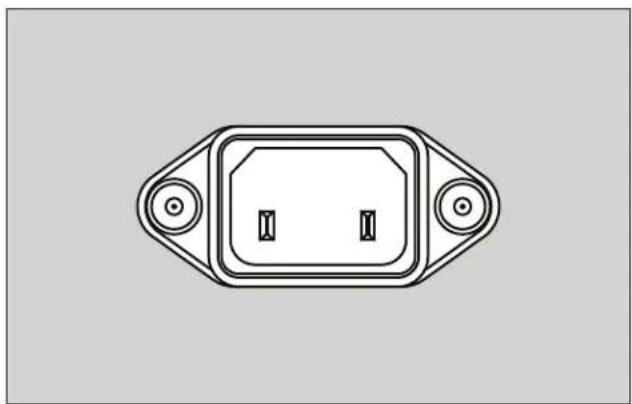
The IEC cord should be firmly inserted into the AC power receptacle on the rear connection panel of the subwoofer, then to any convenient AC wall outlet. The subwoofer also integrates a signal sensing power supply that will go to Standby mode after approximately 60 minutes of no music signal if the top-panel power switch is set to 'Auto (Trigger)'.
Your subwoofer is wired for the power service supplied in the country of original consumer sale. The AC power rating applicable to a particular unit is specified both on the packing carton and on the serial number plate attached to the subwoofer.
If you remove your subwoofer from the country of original sale, be certain that AC power supplied in any subsequent location is suitable before connecting and operating the subwoofer. Substantially impaired performance or severe damage not covered under warranty may occur to the subwoofer if operation is attempted from an incorrect AC power source.
natural_image
Technical line drawing of an electrical outlet connector (no text or symbols)Figure 4. AC Power receptacle
2-Channel Mode
(Line Level RCA or Balanced XLR)

WARNING! Set the Mode switch to Off and unplug your subwoofer before making or breaking any signal connections!
This setup is recommended if your subwoofer will be used in a 2-channel only system. When a signal is connected to the subwoofers Left In/Right In, the Low Pass Filter control is active.
Signal Connection:
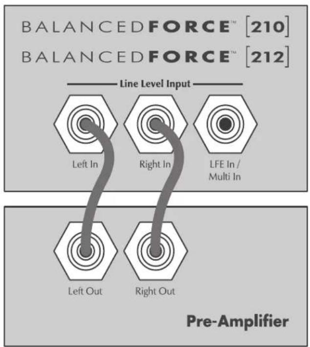
1 Connect the left out/right out from your preamp/receiver to the Left In/Right In of the subwoofer. Use either RCA interconnects, XLR interconnects, or speaker level connections, but choose only one connection method—do not use multiple methods of connection at the same time. Speaker level connections are discussed in detail later in this manual.
Recommended Control Settings:
IMPORTANT! If you intend to use PBK (Perfect Bass Kit) room correction we recommend running PBK and optimizing placement of your subwoofer prior to adjusting the subwoofer's controls. When engaged, PBK will affect the acoustic output of your subwoofer and influence the settings described below.
1 Calculate the number equal to 70% of your main loudspeaker's lowest frequency rating. Set the Low-Pass Filter knob to a setting equal to the resulting number. If the resulting number is lower than 30Hz, set this knob to 30Hz.
If you are using an optional Custom Low-Pass filter there is no need to adjust this knob. When the Custom Low-Pass button is activated it will override the Low-Pass Filter knob setting.
2 Play familiar music with bass content. Increase the Level control until the music has deep extended bass. Be careful to avoid levels that become overwhelming.
3 Try the phase control in different settings until the best blending is obtained. Play familiar music with deep, repetitive bass. Adjust the phase control so the bass notes seem their loudest and without blur when heard from your typical listening position. If you are augmenting MartinLogan loudspeakers, we suggest you start with Phase set at 90° when experimenting. If you are using a Custom Low-Pass filter, we suggest you start with the Phase set at 0°. Custom Low-Pass filters provided for these subwoofers are already phase optimized.
4 If you have completed steps 1–3 and still have weak or booming bass consider adjusting the 25Hz Level knob to compensate for these anomalies. Experiment with the controls and listen to the result. Try to find a position that sounds correct to you. Experiment by changing the Level control while adjusting this knob. Find a position that gives you deep extended bass and good blending with your main speakers. If you still have weak or booming bass you may want to consider moving your subwoofer and go through these setup steps again (especially if it is located in or near a room corner). Remember, room position has a major impact on overall bass performance.
flowchart
graph TD
    A["BALANCED FORCE™ [210"] BALANCED FORCE™ [212]] --> B["Line Level Input"]
    B --> C["Left In"]
    B --> D["Right In"]
    B --> E["LFE In / Multi In"]
    F["Pre-Amplifier"] --> G["Left Out"]
    F --> H["Right Out"]
Figure 5. Signal connection for 2-channel mode.
![BALANCEDFORCE™ [210] BALANCEDFORCE™ [212] Balanced XLR Input Left In Right In LFE In Left Out Right Out Pre-Amplifier](/content/2026/02/421383/images/1d67584eaffcf3af3d2b5a1527e7008615892c38711cecfc38d0f91713e80d75.jpg)
Figure 6. Signal connection for 2-channel mode.
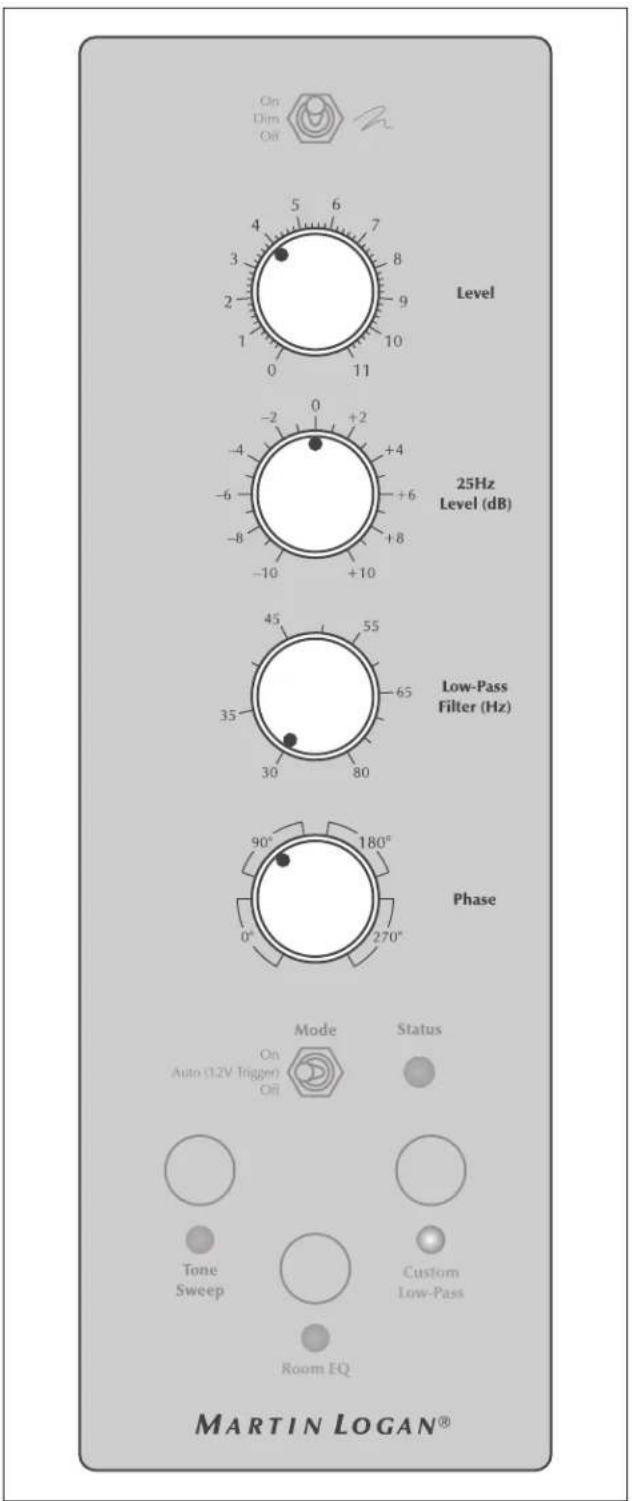
Figure 7. Adjust these controls for 2-channel mode.
Multi-Channel Mode
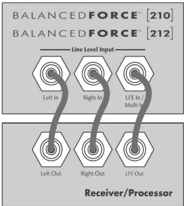
This setup is recommended if you will use your subwoofer in a dedicated home theater or other multi-channel system. When a signal is connected to the subwoofer's LFE In, the setting for the Low-Pass Filter control is not used. Your processor handles most of the bass management.
Signal Connection:
1 Connect the LFE out of the processor to the LFE In. Use either an RCA or an XLR interconnect—do not use both at the same time.
Recommended Control Settings:
IMPORTANT! If you intend to use PBK (Perfect Bass Kit) room correction we recommend running PBK and optimizing placement of your subwoofer prior to adjusting the subwoofer's controls. When engaged, PBK will affect the acoustic output of your subwoofer and influence the settings described below.
1 If your front speakers are large (e.g. full-range floorstanding type speakers) set your processor controls for front speakers to wide, large, or full mode. If your front speakers are small (e.g. bookshelf type speakers) set your processor control for front speakers to narrow, small, or limited mode. Set processor controls for center and effects type speakers to narrow, small, or limited mode. Remember, few center and effects type speakers are designed to go much lower than 70Hz, which means that any bass information in a soundtrack lower than this frequency will normally be lost. When you set your center and effects type speakers to narrow, small, or limited mode, all of the bass lower than the assigned crossover point will be redirected to the subwoofer along with the LFE output—guaranteeing that no bass information from these channels is lost.
Please note: some processors allow the changing of speaker configuration based on source material type. Under these conditions the user may want to run the fronts in narrow, small, or limited mode for multi-channel source material and run the fronts in wide, large, or full mode for 2-channel stereo source material.

WARNING! Based on the performance of most processors it is recommended that MartinLogan center and effects type speakers not be run in large, wide, or full range mode. Doing so may potentially damage the speaker if the processor
attempts to drive the speaker beyond its rated frequency range. This warning also applies to products from other manufacturers.
2 With multi-channel source material playing, adjust the Level control to your preferred level.
3 Adjust the Low-Pass Filter setting to the same frequency as the crossover setting being used in your processor (although this may seem redundant, it actually optimizes effectiveness of the phase control). Try the phase control in different settings until the best blending is obtained. Play familiar music with deep, repetitive bass. Adjust the phase control so the bass notes seem their loudest and without blur when heard from your typical listening position. If you are augmenting MartinLogan loudspeakers, we suggest you start with Phase set at 0° (although we suggest 90° elsewhere, in this specific connection method we suggest 0° since your processor will be doing most of the bass management). If you are using a Custom Low-Pass filter, we also suggest you start with the Phase set at 0°. Custom Low-Pass filters provided for these subwoofers are already phase optimized.
4 If you have completed steps 1–3 and still have weak or booming bass consider adjusting the 25Hz Level knob to compensate for these anomalies. Experiment with the controls and listen to the result. Try to find a position that sounds correct to you. Experiment by changing the Level control while adjusting these knobs. Find a position that gives you deep extended bass and good blending with your main speakers.
5 Use the bass management section of your processor's speaker setup to set the subwoofer level at an appropriate level. Follow the instructions in your processor's manual to fine-tune the subwoofer level.
6 If you have completed steps 1–5 and still have weak or booming bass consider adjusting the 25Hz Level knob to compensate for these anomalies. Experiment with the controls and listen to the result. Try to find a position that sounds correct to you. Experiment by changing the Level control while adjusting this knob. Find a position that gives you deep extended bass and good blending with your main speakers. If you still have weak or booming bass you may want to consider moving your subwoofer and go through these setup steps again (especially if it is located in or near a room corner). Remember, room position has a major impact on overall bass performance.
![BALANCEDFORCE™ [210] BALANCEDFORCE™ [212] Line Level Input Left In Right In LFE In / Multi In Left Out Right Out LFE Out Receiver/Processor](/content/2026/02/421383/images/a5b08dd2074ce58441b6df6d5b37a6f5b885654a8bccab3d78e850e59438fa28.jpg)
Figure 8. Signal connection for multi-channel mode.
![BALANCED FORCE™ [210] BALANCED FORCE™ [212] Balanced XLR Input Left In Right In LFE In Left Out Right Out LFE Out Receiver/Processor](/content/2026/02/421383/images/109a5acf8550cc1a2e5c38e548f4133a18255640be8fee293499a69db8a00b9c.jpg)
Figure 9. Signal connection for multi-channel mode.
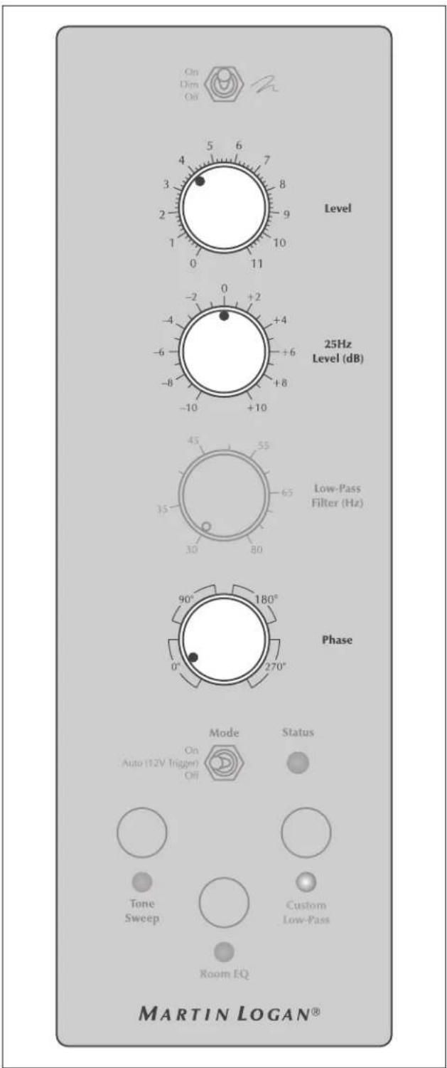
Figure 10. Adjust these controls for multi-channel mode.
Simultaneous 2-Channel/Multi-Channel Mode
The advantage of this dual mode is that you are able to achieve an optimum setup for stereo listening and still allow for multi-channel (movie) mode listening. When listening to stereo source material the system achieves optimum music integration. In this mode the subwoofer plays only below the front main speaker's lowest response frequency. While in movie mode the LFE track and the bass from the surrounds can be fed to the subwoofer using crossover settings from the processor's bass management system.
Signal Connection:
1 Connect the left out/right out from your processor to the Left In/Right In of the subwoofer. Use quality RCA interconnects, XLR interconnects, or speaker level connections. Use either RCA or XLR interconnects, or speaker level connections, but choose only one connection method—do not use multiple methods of connection at the same time for left/right inputs. Speaker level connections are discussed in detail later in this manual.
2 Connect the LFE output of the processor to the subwoofer's LFE In. Use quality RCA or XLR interconnects. Please note, the connection method for the LFE In does not need to match Left In/Right In. If you used RCA interconnects or speaker level connections for Left In/Right In it is acceptable to use XLR for the LFE Input. Be flexible, experiment, and listen to determine what sounds best in your unique installation. Do not use multiple methods of connection at the same time for the LFE input.
Recommended Control Settings:
IMPORTANT! If you intend to use PBK (Perfect Bass Kit) room correction we recommend running PBK and optimizing placement of your subwoofer prior to adjusting the subwoofer's controls. When engaged, PBK will affect the acoustic output of your subwoofer and as a result influence the settings described below.
1 Set your processor controls for front speakers to wide, large, or full mode. If your front speakers are small (e.g. bookshelf type speakers) we recommend that you not use this method for connecting your subwoofer and instead refer to the "Multi-Channel Mode" section. Set processor controls for center and effects type speakers to narrow, small, or limited mode. Remember, few center and effects type speakers are designed to go much lower than 70Hz, which means that any bass information in a soundtrack lower than this frequency will be lost. When you set your center and effects type speakers to narrow, small, or
limited mode, all of the bass lower than the assigned crossover point will be redirected to the subwoofer along with the LFE output—guaranteeing that no bass information from these channels is lost.
Please note: some processors allow the changing of speaker configuration based on source material type. Under these conditions the user may want to run the fronts in narrow, small, or limited mode for multi-channel source material and run the fronts in wide, large, or full mode for 2-channel stereo source material.

WARNING! Based on the performance of most processors it is recommended that MartinLogan center and effects type speakers not be run in large, wide, or full range mode. Doing so may potentially damage the speaker if the processor attempts to drive the speaker beyond its rated frequency range. This warning also applies to products from other manufacturers.
2 Calculate the number equal to 70% of your main loudspeaker's lowest frequency rating. Set the Low-Pass Filter knob to a setting equal to the resulting number. If the resulting number is lower than 30Hz, set this knob to 30Hz.
If you are using a Custom Low-Pass filter you do not need to adjust this knob. When the Custom Low-Pass button is activated it will override the Low-Pass Filter knob.
3 Play familiar music with bass content and turn the level control up until the music has deep bass that is not overwhelming.
4 Try the phase control in different settings until the best blending is obtained. Play familiar music with deep, repetitive bass. Adjust the phase control so the bass notes seem their loudest and without blur when heard from your typical listening position. If you are augmenting MartinLogan loudspeakers, we suggest you start with Phase set at 90° when experimenting. If you are using a Custom Low-Pass filter, we suggest you start with the Phase set at 0°. Custom Low-Pass filters provided for these subwoofers are already phase optimized.
5 With multi-channel source material playing, use the bass management section of your processor's speaker setup to set the subwoofer level at an appropriate level. Follow the instructions in your processor's manual to fine-tune the subwoofer level.
6 If your processor offers the option to setup crossovers for a subwoofer, we recommend that you start with the following
flowchart
graph TD
    subgraph "BALANCEDFORCE™ [210] BALANCEDFORCE™ [212]"
        direction TB
        LeftIn["Left In"] --> RightIn["Right In"]
        RightIn --> LFEInMulti["Multi In"]
    end
    subgraph "Receiver/Processor"
        direction TB
        LeftOut["Left Out"] --> RightOut["Right Out"]
        RightOut --> LFEOut["LFE Out"]
    end
    A["Line Level Input"] --> B["Line Level Input"]
    C["Receiver/Processor"] --> D["Receiver/Processor"]
Figure 11. Signal connection for 2-channel/multi-channel mode.
![BALANCEDFORCE™ [210] BALANCEDFORCE™ [212] Balanced XLR Input Left In Right In LFE In Left Out Right Out LFE Out Receiver/Processor](/content/2026/02/421383/images/12dbd7a96c90549fdd92231b8608d1f39941ce7cc30f63fd2d03009cbaf8f838.jpg)
Figure 12. Signal connection for 2-channel/multi-channel mode.
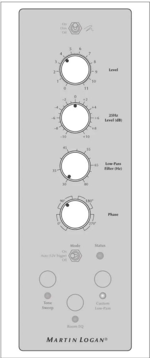
Figure 13. Control Settings for 2-channel/multi-channel mode.
settings—Crossover: 70Hz, High-Pass: 12dB, and Low-Pass: 24dB. The optimal setting for these options may vary depending on your room and listening preferences. Experiment and listen for what sounds best to you.
7 If you have completed steps 1–5 and still have weak or booming bass consider adjusting the 25Hz Level knob to compensate for these anomalies. Experiment with the controls and listen to the result. Try to find a position that sounds correct to you. Experiment by changing the Level control while adjusting this knob. Find a position that gives you deep extended bass and good blending with your main speakers. If you still have weak or booming bass you may want to move your subwoofer's location and go through these setup steps again (especially if the sub is located in or near a room corner). Remember, room position has a major impact on overall bass performance.
Using Speaker Level Inputs
This connection method is recommended if your subwoofer will be used in a 2-channel only system with full-range front loudspeakers. To connect using Speaker Level Input the speaker cable should be terminated using banana style plugs. The Low-Pass Filter knob is applied to the signal received through these inputs. If the Custom Low-Pass button is activated it will override the Low-Pass Filter knob.
Speaker Level Inputs are an alternative to using RCA or XLR interconnects. If you use the Speaker Level Inputs do not use RCA or XLR at the same time for Left In / Right In connections. If you use
the Speaker Level Inputs it is okay to still use RCA or XLR for the LFE connection.
Connect the left and right outputs of your amplifier to the subwoofer's Speaker Level Input (Left In/Right In). Use quality speaker cable and banana plugs. Be consistent and make sure the + and - terminals from your amplifier are attached to the matching + and - terminals on the subwoofer.
If your amplifier only has one set of outputs you may connect your amplifier to your speakers as normal and run an additional set of cables from your speakers to the subwoofer's Speaker Level Input.
![BALANCED FORCE™ [210] BALANCED FORCE™ [212] Speaker Level Input + Left In - + Right In - + Left Out - + Right Out - Amplifier](/content/2026/02/421383/images/5d40ba257e105dca14c305df69903c4daef2a55bb67b7eef76921341a0716ba0.jpg)
Figure 14. Using speaker level inputs.
Loading a Custom Low-Pass Filter
To add a custom low-pass filter to your subwoofer you must first visit MartinLogan.com:
• www.martinlogan.com/balancedforce210/download
• www.martinlogan.com/balancedforce212/download
Download the appropriate file to match your main speakers. Save the custom low-pass file in the root directory of a USB flash drive. To assure a successful upload to your subwoofer we recommend having no other files or folders on the flash drive—the subwoofer can only load one file at a time.
Insert the flash drive into the USB Input on the back of the subwoofer. The subwoofer will automatically find the file and load the custom low-pass filter. When a USB flash drive is connecting to the USB Input the USB Status light indicates the following information:
No color: Idle (no USB device currently connected).
Flashing Green: Reading USB flash drive.
Solid Green: Success. File found and loaded. Okay to remove USB flash drive.
Solid Red: Failed. No changes made. Cannot find file or flash drive not formatted using FAT32 file system (see FAQ and Troubleshooting).
Flashing Red: Failed. Cannot read drive due to electrical problem.
Updating Firmware
Please note, the subwoofer will load whichever firmware revision is on the connected flash drive—even if the firmware revision on the flash drive is older than what is currently loaded on your subwoofer. To make sure you're installing the latest firmware revision check MartinLogan.com before updating your subwoofer:
• www.martinlogan.com/balancedforce210/download
• www.martinlogan.com/balancedforce212/download
To check which revision your subwoofer currently has installed, press the Custom Low-Pass button and hold it for 3 seconds. The Tone Sweep LED light will blink a number of times that is equal to
the current revision number (e.g. two blinks = revision 2 firmware).
Please note, updating the firmware should not erase settings for PBK (Perfect Bass Kit) and the Custom Low-Pass filter. A notice will be posted on our website alongside the firmware download if, for some unforeseen reason, a specific firmware revision must erase these settings—otherwise, these setting should still be in place after a firmware update.
1 To update your subwoofer's firmware you must first visit MartinLogan. (www.martinlogan.com/balancedforce210/download or www.martinlogan.com/balancedforce212/download) and download the latest firmware file for your subwoofer model. Save the firmware file in the root directory of a USB flash drive. To assure a successful upload to your subwoofer we recommend having no other files or folders on the flash drive—the subwoofer can only load one file at a time.
2 Unplug the subwoofer from the AC outlet.
3 Insert the flash drive into the USB Input on the back of the subwoofer.
4 Reconnect the subwoofer to the AC outlet. The USB Status LED will continually blink red-green-red-green while the firmware is being updated—this blinking may pause momentarily during the update. Do not remove the flash drive until the LED stops blinking and shows a solid color for at least 5 seconds. See below.
When a USB flash drive is connecting to the USB Input the USB Status light indicates the following information:
No color: Idle (no USB device currently connected).
Blinking Green/Red: Reading USB flash drive.
Solid Green (for over 5 seconds): Success. File found and loaded. Okay to remove USB flash drive.
Solid Red (for over 5 seconds): Failed. No changes made. Cannot find file or flash drive not formatted using FAT32 file system (see FAQ and Troubleshooting).
Blinking Red: Failed. Cannot read drive due to electrical problem.
PBK Room Correction
On the rear panel of your subwoofer is a mini-USB input labeled "PBK Input" which allows for connection of MartinLogan's Perfect Bass Kit (PBK™). The procedure for running PBK room correction is outlined in the PBK manual. PBK is sold separately.
The PBK system employs your computer*, connected via USB to a microphone and your MartinLogan subwoofer, to identify problem areas in your listening environment. The PBK processes information from multiple data points and configures the optimal solution, achieving pinpointaccurate room response.
Like the best room measurement systems available today, PBK utilizes multiple measurement points, at least five—but up to ten—individual data positions, allowing PBK to learn the individual characteristics of your room.
The PBK employs your computer's processor to calculate correction curves for each measurement point, substantially minimizing the rounding errors of less sophisticated "calculators", like those used in standard room equalization systems. Additionally, PBK's software is capable of calibrating itself to the individual microphone included in the kit, eliminating interference that would otherwise skew the data.
MartinLogan's PBK™ (Perfect Bass Kit) is designed to adjust performance of specific MartinLogan subwoofers to reduce room induced bass anomalies. PBK is not a replacement for other room correction systems designed to optimize multi-channel audio systems.
When beginning the task of optimizing an audio system's performance, the first step should always be proper setup of the front, center, and surround speakers. Proper setup of these speakers requires proper positioning, toe in, and (if available) adjusting a speaker's built-in bass level controls. The next step should be running PBK to adjust the subwoofer's output to account for room interactions. After running PBK, the subwoofer's performance and integration with the main speakers should be optimized by adjusting the subwoofer's level, phase, low-pass filters, and other controls.
Only after proper setup of speakers and subwoofer(s), including running PBK on the subwoofer(s), is it time to run your processor's full-range room correction system to help balance overall system performance within the room.
Although PBK is designed to adjust the subwoofer's output to minimize sonic anomalies caused by room interactions, it is always recommended to use traditional methods to achieve a flat response before implementing digitally based room correction. Remember, subwoofer placement is one of the most influential parameters when dealing with anomalous low-frequency room interactions—listening position is equally important to bass response but is often dictated by other factors that are more difficult to change. Some users will find that running PBK and examining the resulting graphs may help optimize the subwoofer's placement. To do this, connect PBK and use the system to take measurements. The resulting graph displayed on the computer* will likely show peaks and valleys in the measured room response. Instead of loading the PBK settings to your subwoofer, move the subwoofer and take the measurements again. Continue moving and measuring until you achieve a frequency response without any wide bandwidth response dips. The PBK will correct the peaks. After you've determined an ideal subwoofer placement, fine tune the subwoofer's performance by running PBK one last time and uploading the PBK settings to your subwoofer.
When a computer is connecting via a mini-USB to the PBK Input, the light indicates the following statuses:
No color: Idle (no USB device currently connected).
Solid Green: PBK connection okay.
Solid Red: PBK connection problem.
*NOTE: Please refer to PBK manual and related instructions for computer compatibility information when running PBK.
Multi Out—Daisy Chaining Multiple Subwoofers
If you are daisy chaining multiple identical subwoofers, connectMulti Out from the controlling subwoofer to the LFE In / Multi In on the next subwoofer. Additional subwoofers may be connected using this same pattern. The first subwoofer in the chain will control all other subwoofers down stream (except for the light brightness setting of individual subwoofers). We recommend connecting no more than four subwoofers in a daisy-chain—more may be acceptable, depending on your specific installation. Experiment and listen for what sounds best to you.
Signal Connection:
1 Connect the first subwoofer to your system using one of the connection methods previously described in this manual (e.g. 2-Channel Mode, Multi-Channel Mode, or Simultaneous 2-Channel/Mult-Channel Mode).
2 Connect the Multi Out of the subwoofer to LFE In / Multi In of the next subwoofer. Use a quality RCA interconnect.

WARNING! Never connect the the subwoofer's Multi-Out to the input of an amplifier connected to a full-range speaker. The encoded signal from the Multi-Out contains high-frequency information that may potentially damage tweeters.
3 Repeat step 2 for each additional subwoofer in the chain.
Recommended Control Settings:
1 For the first subwoofer in the chain, adjust the control settings using the procedure described for the connection method used (e.g. 2-Channel Mode, Multi-Channel Mode, or Simultaneous 2-Channel/Multi-Channel Mode).
If you are using a custom low-pass filter, load the custom low-pass only on the first subwoofer. There is no need to load this filter on additional subs.
If you are using PBK room correction, after connecting all of the subs, attach the PBK system to the first sub and run PBK as you would if you were only measuring one subwoofer.
2 The Level, 25Hz Level, Low-Pass Filter, and Phase settings for additional subwoofer will no longer function. The Tone Sweep, Room EQ, and Custom Low Pass buttons will also no longer function. The Mode control on additional subs must be set to 'Auto (Trigger)' to allow the power status of additional subwoofers to synchronize with the first subwoofer.
Regardless of how you use your sub, experimentation often results in better sound. Don't be afraid to try different settings. You can always return the controls to their previous settings.
Optional Wireless Connection
An optional wireless transmitter/receiver system manufactured by MartinLogan may be available from your local dealer. Please check with them for availability.
![BALANCEDFORCE™ [210] BALANCEDFORCE™ [212] —— Line Level Input — Multi Out Left In Right In LFE In / Multi In BALANCEDFORCE™ [210] BALANCEDFORCE™ [212]](/content/2026/02/421383/images/7b8af88519f2b7d93358ebc227743e47b239ba202d2fba0981a7510f8e2c46ab.jpg)
Figure 15. Connecting multiple subs.
Subwoofer Position
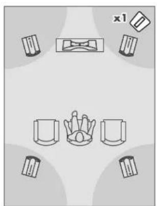
Generally, subwoofers have the most output when placed in the corner of a room. However, this can also exaggerate the subwoofers output making blending with the main speakers difficult. If you choose to place the subwoofer in a corner near the front of the room it should be placed in such a way that there are 2 inches minimum between the woofers and the wall. Preferably, the subwoofer should be diagonal to the corner so each woofer is equidistant from the adjacent wall. This will avoid blocking the output of either woofer.
Before deciding on a permanent corner placement, experiment with other positions. Locations away from corners often prove more effective in providing ideal low-frequency performance and blend with the main speakers. If the subwoofer sounds like it has too much upper bass energy try pulling it away from the wall and toward the listening position (moving it out of the corner). This will lessen the wall and corner reinforcement of these problematic frequencies and likely smooth out the response. Repeat the setup procedure with the subwoofer controls after moving to a new position.
Please note, some users may find that using PBK to take subwoofer response measurements will help optimize subwoofer placement. For more information please refer to the PBK section of this manual.
natural_image
Top-down view of a table setting with chairs, tables, and objects (no text or symbols)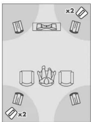
natural_image
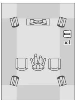
Top-down view of a table setting with six items arranged around a central table (no text or symbols visible)Figure 17a & 17b. Experiment with corner placements.
natural_image
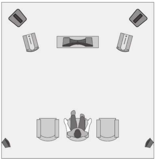
Top-down view of a meeting room layout with furniture and objects (no text or symbols)Figure 16. A typical 5.1-channel home theater setup. Note the corner placement of the subwoofer at the front of the listening room—this is the location where many people initially place a sub. However, with experimentation locations away from corners often prove more effective in providing an ideal low-frequency performance and blend with the main speakers.
natural_image
Top-down view of a table with six items arranged around a central table (no text or symbols visible)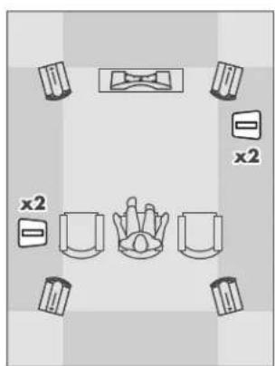
natural_image
Top-down view of a table setup with chairs, tables, and objects (no text or symbols visible)Figure 18a & 18b. Experiment with non-corner placements.
Installing in a Cabinet
Occasionally, there is a desire to place subwoofer(s) inside of cabinetry. Your sub's unique two-woofer design does not compromise the ability to be successfully installed in such a configuration. However, it is recommended, as with any quality multi-driver sub, that there be a minimum of three inches of open space between the cabinet and the front, left and right sides of the subwoofer.
Ask Your Dealer
Your MartinLogan dealer can suggest many options for optimal subwoofer placement. They also have many tools at their disposal, such as experience, familiarity with the associated equipment, and even sound analysis equipment which may make the task of determining optimal subwoofer placement easier.
Solid Footing
After using and experimenting with your sub, you may want to use ETC (energy transfer coupler) spikes. With the use of these spikes, the subwoofer will become more firmly planted on the floor and, consequently, bass will tighten and imaging will become more coherent and detailed. It is best not to implement the spikes, however, until you are secure in the positioning, as the spikes can damage the floor if the subwoofer is moved. The feet that attach to the bottom of the subwoofer use a common 3/8 - 16 thread.
1 On a soft, padded surface, carefully lay your subwoofer on its front to gain access to the bottom.
2 Remove existing feet or spikes. Thread new spikes into holes and screw them in all of the way. If the subwoofer does not sit level loosen one spike until level is achieved.
3 By hand, tighten the jam nut snugly against the cabinet. Do not over tighten the nut.
4 Right the speaker. Caution: Make sure your hands and any cabling are clear of the spikes. Do not slide subwoofer as spikes are sharp and can damage your floor or carpet.
5 Adjust to level by rotating spikes. By hand, tighten the jam nut snugly against the cabinet when you are satisfied the subwoofer is level.
Caution: Walking the subwoofer may result in over tightening and/or a broken spike.
Enjoy Yourself
Your subwoofer will benefit from care in setup. With the above placement tips in mind you will find, over months of listening, that small changes can result in measurable differences. As you live with your subwoofer do not be afraid to experiment with positioning until you find the optimal relationship between your room, settings, and subwoofer, that gives to you the best results. Your efforts will be rewarded.
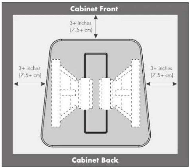
Figure 19. Placing the subwoofer in a cabinet requires a minimum of three inches of open space on the front, left and right.
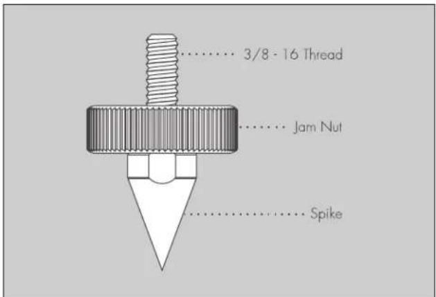
Figure 20. An ETC (Energy Transfer Coupler) Spike
Your Room
This is an area that requires both a little background to understand and some time and experimentation to attain the best performance from your system.
Your room is actually a component and an important part of your system. This component is a large variable and can dramatically add to or subtract from a great sonic experience.
All sound is composed of waves. Each frequency has its own wave size, with the lower bass frequencies literally ranging from 10 feet to as much as 55 feet. Your room participates in this wave experience like a swimming pool with waves reflecting and becoming enhanced depending on the size and shape of the room and the types of surfaces in the room.
Remember that your audio system can actually generate all of the information required to recreate a sonic event in time, space, and tonal balance. Acoustically, the role of an ideal room would be to neither diminish nor contribute to that information. However, nearly every room does so to some degree.
Terminology
Standing Waves
Sound coming from a subwoofer bounces around in a room until a pattern emerges—this is called a standing wave. Typically, this is only a problem with frequencies below 100Hz. When this happens, different parts of your room experience either an excess or a lack of bass. Standing waves exist in all rooms and a different pattern exists for different frequencies in the bass.
Some people believe that having a room without parallel walls will eliminate this effect. The truth is that non-parallel walls only generate different standing wave patterns than those that occur in rectangular rooms.
Usually, you excite most of the standing waves in a room by putting the subwoofer in a corner. Listening position determines which standing waves you will experience. For instance, if you sit in a corner you will hear most of the standing waves. This can be an overpowering experience. Sitting next to a wall can also intensify the levels of the standing waves that are experienced.
If you still have an excess or lack of bass after adjusting subwoofer placement and controls, PBK room correction will help adjust acoustic output of your subwoofer(s) to minimize undesired acoustic anomalies and optimize the performance of your subwoofer within your unique listening environment.
Resonant Surfaces and Objects
All of the surfaces and objects in your room are subject to the frequencies generated by your system. Much like an instrument, they will vibrate and "carry on" with the music, and may contribute in a negative way to the sound. Ringing, booming, and even brightness can occur simply because surfaces and objects are "singing along" with your speakers. This subwoofer's Tone Sweep control can aid in identifying and resolving contributions from resonant surfaces and objects.
Resonant Cavities
Small alcoves or closet type areas in your room can be chambers that create their own "standing waves" and can drum their own "one note" sounds. This subwoofer's Tone Sweep control can aid in identifying and resolving contributions from resonant cavities.
It had long been the practice of stereo buffs to connect their television to a stereo system. The advantage was the use of the larger speakers and more powerful amplifier of the stereo system. Even though the sound was greatly improved, it was still mono and limited by the broadcast signal.
In the late 1970's and early 1980's two new home movie formats became widely available to the public: VCR and laser disc.
By 1985, both formats had developed into very high quality audio/video sources. In fact, the sonic performance of some video formats exceeded audio-only formats. Now, with theater-quality sound available at home, the only element missing was the "surround sound" presentation found in movie houses.
Fortunately, Dolby and DTS encoded DVD's emerged with the same surround sound information encoded on home releases as the theatrical release. Additionally, new high-resolution home viewing formats such as Blu-ray as well as high-definition content provided via cable, satellite, and internet have evolved which include multi-channel encoded audio that can match master tape quality. All that is required to retrieve this information is a decoder and additional speakers and amps to reproduce it.
Home theater is a complex purchase and we recommend that you consult your local MartinLogan dealer, as they are well versed in this subject.
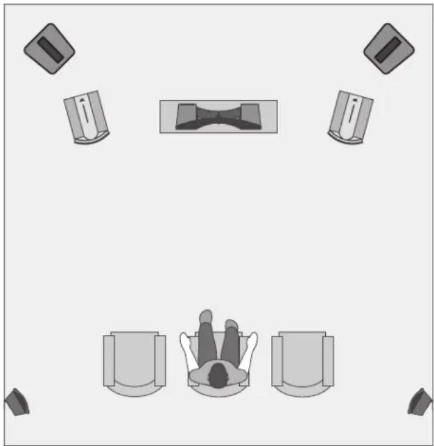
Each piece of a surround system can be purchased separately. Take your time and choose high quality components. No one has ever complained that the movie was too real. The following list and descriptions will give you only a brief outline of the responsibilities and demands placed on each speaker.
Front Left and Front Right
If these speakers will be the same two used for your stereo playback, they should be of very high quality and able to play loudly (over 102 dB) and reproduce bass below 80 Hz.
Center Channel
This is the most important speaker in a home theater system, as almost all of the dialogue and a large portion of the front speaker information is reproduced by the center channel. It is important that the center speaker be extremely accurate and matches well with the front left and right speakers, and that it is recommended for use as a center speaker. This is not the place to cut corners.
Surround/Effects Speakers
We recommend that the surround/effects speakers play down to at least 80 Hz. Surround speakers contain the information that makes it appear that planes are flying over your head. Some may suggest that this is the place to save money and purchase small, inexpensive speakers. However, discrete full-resolution multi-channel digital encoding is now the standard and the demands on surround speakers have increased.
Subwoofer
With any good surround system you will need one or more high-quality subwoofers (the .1 in a 5.1, 6.1, or 7.1 channel surround system). Most movie soundtracks contain large amounts of bass information as part of the special effects. Good subwoofers will provide a foundation for the rest of the system.
natural_image
Top-down diagram of a meeting room layout with furniture and objects (no text or symbols)Figure 21. A typical 5.1-channel home theater setup.
BalancedForce™ For Cleaner Bass
Resulting from an equal and opposite reaction to the cone's movement, strong bass causes all traditional subwoofer enclosures to generate acoustic vibrations. You feel this by touching the cabinet. Although the "physics" of this phenomenon actually cause a subwoofer cabinet to resonate or even dance, most subwoofer designers apply weight or mass to the cabinet to minimize such disturbances, but still leave one byproduct—"smeared bass". Vibrations translated from the woofer to the cabinet actually alter the bass causing a loose and "fuzzy" sound.
This subwoofer uses a BalancedForce bass configuration to nullify cabinet vibrations. Originally engineered for our cost-no-object, state-of-the-art Statement™ E2 system, BalancedForce uses drivers mounted at opposing angles. Your subwoofers drivers, spaced 180 degrees apart, operate in exact opposition, resulting in maximum cancellation delivering the ideal—pure bass energy with a reduction in cabinet contributions to the room as high as 25dB over traditional subwoofer resonance solutions!
Proprietary Switching Amplifiers
BalancedForce subs match powerful proprietary switching amps with incredible woofer drivers resulting in tightly defined bass while keeping distortion at the lowest possible levels. The BalancedForce 210 features an 850 watt Class D switching amplifier capable of a 1700 watt dynamic peak operating at over 90% efficiency. BalancedForce 212 features dual 850 watt amplifiers (one for each woofer) with a total system power of 1700 watts (3400 watts dynamic peak).
Low-noise, high-power transformers and switching power supplies feature high-quality MOSFET transistors, noise-suppression networks, and control circuitry to provide tremendous levels of current with extremely low levels of distortion. Split power supply rails minimize distortion while maximizing switching efficiency. Military grade glass epoxy circuit boards, temperature sensors, and protection circuitry guarantee quality sound and reliable trouble-free operation.
25Hz Level Control
25Hz Level control allows custom sound tailoring capability found in few subwoofers. A room, especially when small, can greatly exaggerate bass. The 25Hz Level control knob increases or decreases lower bass to compensate for these room anomalies and allows increased deep bass if you desire a sense of subsonic energy at the lowest frequencies.
PBK (Perfect Bass Kit)
Although the controls on your subwoofer allow you to fine tune and optimize bass performance in your room, PBK allows you to also correct for the negative effects of the room itself. Even when a subwoofer is perfectly positioned, the room can have a dramatic impact on bass performance. Room dimensions, dead spots, archways, furniture, and countless other factors can turn a room into an additional instrument playing alongside musicians or movie scores with unwanted contributions of coloration and resonance. PBK is sold separately and is strongly recommended.
Optional Custom Low-Pass Filters
Seamless blending between a subwoofer and full-range loudspeaker is, at the best of times, challenging—and when you're dealing with the highest levels of loudspeaker performance there is no room for error. The addition of a custom low-pass filter takes the headache out of achieving superb low-frequency performance.
Custom low-pass filters are specifically designed to optimize subwoofer integration by precisely matching the low-frequency roll off of specific loudspeaker models. Once a custom low-pass filter is uploaded to a subwoofer, setup is only a matter of adjusting the phase and level. This custom filter is applied only to the left and right inputs of your subwoofer. The sub's LFE input remains unfiltered, which allows surround preamp/processors to send low-frequency information for the center, surround, and LFE channels without compromising the performance of your main speakers.
Frequently Asked Questions
Why won't my subwoofer read my USB flash drive when I attempt to add a custom low-pass filter or update my firmware?
When connecting a USB flash drive to the subwoofer's USB Input, the drive must be formatted using a FAT32 file system. To learn more about formatting a flash drive using FAT32 please refer to your computer's help documentation. Most flash drives (under 32GB) come pre-formatted as FAT32. Reformat your flash drive only if the upload doesn't work.
How do I clean my subwoofer?
Use a dust free cloth or a soft brush to clean your subwoofer. We also recommend microfiber cloths.
Is it safe to set things on my subwoofer?
While your subwoofer is designed with a durable, stain-resistant surface, we advise you treat this like any piece of fine furniture and not to set anything on your subwoofer—especially containers holding liquids.
Is there likely to be any interaction between my subwoofer and the CRT television in my Audio/Video system?
Yes. The subwoofer doesn't use a shielded driver. We recommend 3 feet between the subwoofer and video components that are susceptible to magnetic fields. Modern flat screen televisions are not affected by the magnets in your subwoofer.
Will my electric bill go 'sky high' by leaving my subwoofer plugged in all the time?
No. The subwoofer, when the power switch is set to 'Auto' or 'Standby', will draw about 30 watts when idle.
Should I unplug my sub during a thunderstorm?
Yes, or before. It's a good idea to disconnect all of your audio/video components during stormy weather.
I disposed of my speaker's original packaging. Can I buy new packaging for my speaker?
Yes, replacement packing is usually available for current and recent MartinLogan products. However, replacement packaging may sometimes be quite expensive and we encourage listeners to save their original packaging materials. MartinLogan cartons will collapse and flatten for easy storage. Foam and additional packing materials may be safely stowed in a large plastic bag.
Troubleshooting
No Output
- Check that all your system components are turned on.
- Check that the power switch on the subwoofer is set to either 'Auto (Trigger)' or 'On'.
- Check your wires and connections.
- Check all interconnecting cables.
• Make sure the level control is not turned down.
• If the problem persists, contact your dealer.
Muddy Bass
- Check placement. Try moving the subwoofer closer to the front and side walls.
- Check the type of feet that are being used. Try installing the ETC spikes.
- Decrease the level.
- Check your processor setup.
- Check that the Low-Pass Filter frequency is no set too high.
- If the problem persists, contact your dealer.
Hums or Unusual Sounds
- Turn the subwoofer off, unplug all signal inputs, turn the subwoofer back on and turn up the level. If the problem disappears, the hum is originating elsewhere in your system.
- Connect the subwoofer's AC connection to the same AC circuit as the pre amp.
• If the problem persists, contact your dealer.
Warranty and Registration
Your subwoofer is provided with an automatic Limited 90 Day Warranty coverage. You have the option, at no additional charge, to receive Limited 3-Year Warranty coverage. To obtain the Limited 3-Year Warranty coverage you need to complete and return the Certificate of Registration, included with your subwoofer, and provide a copy of your dealer receipt, to MartinLogan within 30 days of purchase.
For your convenience MartinLogan also offers online warranty registration at www.martinlogan.com.
MartinLogan may not honor warranty service claims unless we have a completed Warranty Registration card on file! If you did not receive a Certificate of Registration with your new subwoofer you cannot be assured of having received a new unit. If this is the case, please contact your authorized MartinLogan dealer.
Serial Number
The serial number is located near the bottom of the backplate. The serial number is also located on the shipping carton. Each individual unit has a unique serial number.
Service
In the rare event that your MartinLogan product should require service please contact the dealer from whom the product was purchased. In most cases your dealer will be able to assist you in troubleshooting and resolving the issue. If the dealer is unable resolve the issue or if there is no local dealer in your area contact MartinLogan customer service directly by using the service request form at www.martinlogan.com or by calling 785-749-0133.
Before returning any product to MartinLogan for service first contact the service department for an RMA number. Incoming shipments will only be accepted if labeled with a MartinLogan issued RMA number.
Should you be using a MartinLogan product in a country other than the one in which it was originally purchased, please note the following:
1 The appointed Martinlogan distributor for any given country is responsible for warranty servicing only on units distributed by or through it in that country in accordance with its applicable warranty.
2 Should a MartinLogan product require servicing in a country other than the one in which it was originally purchased the end user may seek to have repairs performed by the nearest MartinLogan distributor, subject to that distributor's local servicing policies. All cost of repairs (parts, labor, and transportation) must be born by the owner of the MartinLogan product.
3 If, after owning your MartinLogan product for six months, you relocate to a country other than the one in which it was purchased, your warranty may be transferable. Contact MartinLogan for details.
| BalancedForce 210* | BalancedForce 212* | |
| System Frequency Response. . . . | 20-120 Hz ±3dB. Anechoic through the LFE effects input. | 18-120 Hz ±3dB. Anechoic through the LFE effects input. |
| Low Pass Filter Frequencies . . . . | 30-80Hz | 30-80Hz |
| Phase . . . . . . . . . . . . . . . . . . . . . . . . . . . . . . . . . . . . . . . . . . . . . . . . . . . . . . . . . . . . . . . . . . . . . . . . . . . . . . . . . . . . . . . . . . . . . . . . . . . . | 0°, 90°, 180°, 270° | 0°, 90°, 180°, 270° |
| 25Hz Level Control. . . . . . . . . . . . . . . . . . . . . . . . . . . . . . . . . . . . . . . . . . . . . . . . . . . . . . . . . . . . . . . . . . . . . . . . . . . . . . . . . . . . . . . . . . . . . . . . . . . . Power . . . . . . . . . . . . . . . . . . . . . . . . . . . . . . . . . . . . . . . . . . . . . . . . . . . . . . . . . . . . . . . . . . . . . . . . . . . . . . . . . . . . . . . . . . . . . . . . . . . Woofers. . . . . . . . . . . . . . . . . . . . . . . . . . . . . . . . . . . . . . . . . . . . . . . . . . . . . . . . . . . . . . . . . . . . . . . . . . . . . . . . . . . . . . . . . . . Amplifiers . . . . . . . . . . . . . . . . . . . . . . . . . . . . . . . . . . . . . . Inputs (RCA). . . . . . . . . . . . . . . . . . . . . . . . . . Inputs (XLR) . . . . . . . . . . . . . . . . . . . Inputs (Speaker Level) . . . . . . . . . Inputs (12V Trigger) . . . . . . . . . . . Inputs (USB) . . . . . . . . . . . . . . . . Output (RCA) . . . . . . . . . . . . . . . Input Impedance . . . . . . . . . . . . . . . . Power Draw . . . . . . . . . . . . Weight. . . . . . . . . . . . Size (H x W x D) . . . . . . . . . . . . . . . . . . . . . . . . . . . . . . . . . . . . . . . . . . . . . . . . . . . . . . . . . . . . . . . . . . . . . . . . . . . . . . . . . . . . . . . . . . . . . . . . . . . |
AC. Abbreviation for alternating current.
Active crossover. Uses active devices (transistors, IC's, tubes) and some form of power supply to operate.
Amplitude. The extreme range of a signal. Usually measured from the average to the extreme.
Arc. The visible sparks generated by an electrical discharge.
Bass. The lowest frequencies of sound.
Bi-Amplification. Uses an electronic crossover, or line-level passive crossover, and separate power amplifiers for the high and low frequency loudspeaker drivers.
Capacitance. That property of a capacitor which determines how much charge can be stored in it for a given potential difference between its terminals, measured in farads, by the ratio of the charge stored to the potential difference.
Capacitor. A device consisting of two or more conducting plates separated from one another by an insulating material and used for storing an electrical charge. Sometimes called a condenser.
Clipping. Distortion of a signal by its being chopped off. An overload problem caused by pushing an amplifier beyond its capabilities. The flat-topped signal has high levels of harmonic distortion which creates heat in a loudspeaker and is the major cause of loudspeaker component failure.
CLS. The abbreviation for curvilinear line source.
Crossover. An electrical circuit that divides a full bandwidth signal into the desired frequency bands for the loudspeaker components.
dB (decibel). A numerical expression of the relative loudness of a sound. The difference in decibels between two sounds is ten times the Base 10 logarithm of the ratio of their power levels.
DC. Abbreviation for direct current.
Diffraction. The breaking up of a sound wave caused by some type of mechanical interference such as a cabinet edge, grill frame or other similar object.
Diaphragm. A thin flexible membrane or cone that vibrates in response to electrical signals to produce sound waves.
Distortion. Usually referred to in terms of total harmonic distortion (THD), which is the percentage of unwanted harmonics of the drive signal present with the wanted signal. Generally used to mean any unwanted change introduced by the device under question.
Driver. See transducer.
Dynamic Range. The range between the quietest and the loudest sounds a device can handle (often quoted in dB).
Efficiency. The acoustic power delivered for a given electrical input. Often expressed as decibels/watt/meter (dB/w/m).
ESL. The abbreviation for electrostatic loudspeaker.
Headroom. The difference, in decibels, between the peak and RMS levels in program material.
Hybrid. A product created by the marriage of two different technologies. Meant here as the combination of a dynamic woofer with an electrostatic transducer.
Hz (Hertz). Unit of frequency equivalent to the number of cycles per second.
Imaging. To make a representation or imitation of the original sonic event.
Impedance. The total opposition offered by an electric circuit to the flow of an alternating current of a single frequency. It is a combination of resistance and reactance and is measured in ohms. Remember that a speaker's impedance changes with frequency, it is not a constant value.
Inductance. The property of an electrical circuit by which a varying current in it produces a varying magnetic field that introduces voltages in the circuit or in a nearby circuit. It is measured in henrys.
Inductor. A device designed primarily to introduce inductance into an electrical circuit. Sometimes called a choke or coil.
Linearity. The extent to which any signal handling process is accomplished without amplitude distortion.
Midrange. The middle frequencies where the ear is the most sensitive.
Passive crossover. Uses no active components (transistors, IC's, tubes) and needs no power supply (AC, DC, battery) to operate. The crossover in a typical loudspeaker is of the passive variety. Passive crossovers consist of capacitors, inductors and resistors.
Phase. The amount by which one sine wave leads or lags a second wave of the same frequency. The difference is described by the term phase angle. Sine waves in phase reinforce each other; those out of phase cancel.
Pink noise. A random noise used in measurements, as it has the same amount of energy in each octave.
Polarity. The condition of being positive or negative with respect to some reference point or object.
RMS. Abbreviation for root mean square. The effective value of a given waveform is its RMS value. Acoustic power is proportional to the square of the RMS sound pressure.
Resistance. The property of a conductor by which it opposes the flow of electric current, resulting in the generation of heat in the conducting material, usually expressed in ohms.
Resistor. A device used in a circuit to provide resistance.
Resonance. The effect produced when the natural vibration frequency of a body is greatly amplified by reinforcing vibrations at the same or nearly the same frequency from another body.
Sensitivity. The volume of sound delivered for a given electrical input.
Stator. The fixed part forming the reference for the moving diaphragm in a planar speaker.
THD. The abbreviation for total harmonic distortion. (See Distortion)
TIM. The abbreviation for transient intermodulation distortion.
Transducer. Any of various devices that transmit energy from one system to another, sometimes one that converts the energy in form. Loudspeaker transducers convert electrical energy into mechanical motion.
Transient. Applies to that which lasts or stays a short time. A change from one steady-state condition to another.
Tweeter. A small drive unit designed to reproduce only high frequencies.
Wavelength. The distance measured in the direction of progression of a wave, from any given point characterized by the same phase.
White noise. A random noise used in measurements. It has the same amount of energy at each frequency.
Woofer. A drive unit operating in the bass frequencies only. Drive units in two-way systems are not true woofers but are more accurately described as being mid/bass drivers.
Contenu Introduction
Contenu 42
Introduction 42
Commandes.... 43
PBK (Perfect Bass Kit) 61
Right In/Left In (Balanced XLR)
LFE In (Balanced XLR)
Right In/Left In (Line Level)
LFE In / Multi In (Line Level)
Left In / Right In (Speaker Level)
natural_image
Technical line drawing of an electrical outlet connector (no text or symbols)• www.martinlogan.com/balancedforce210/download
• www.martinlogan.com/balancedforce212/download
• www.martinlogan.com/balancedforce210/download
• www.martinlogan.com/balancedforce212/download
![Line Level Input Left In Right In LFE In / Multi In Multi Out BALANCED FORCE™ [210] BALANCED FORCE™ [212]](/content/2026/02/421383/images/c250a513694f159847704df7017b2482e27941c9243e07ee8bb5cb02b4302dd8.jpg)
natural_image
Top-down view of a table setting with six items arranged around a central table (no visible text or symbols)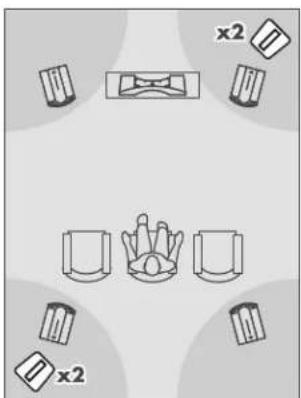
natural_image
Top-down view of a table setting with four items arranged around a central table (no text or symbols visible)natural_image
Top-down view of a person reclining in a chair with four bookshelves and a table in the background (no text or symbols)natural_image
Top-down view of a table setting with six items arranged around a central table (no text or symbols visible)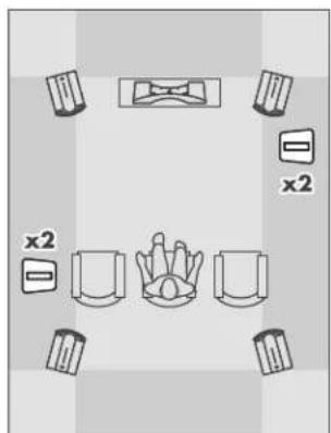
natural_image
Top-down view of a table setting with icons for seating arrangement (no text or symbols)natural_image
Top-down diagram of a person reclining in a chair with four chairs and three speakers, no text or symbols presentPBK (Perfect Bass Kit)
natural_image
Technical line drawings of mechanical components including a base, clamping mechanism, and cable assembly (no text or symbols)![BALANCED FORCE™ [210] BALANCED FORCE™ [212] MARTIN LOGAN® Level 25Hz Level (dB) Low-Pass Power (Hz) Phase Mode Station Auto I/O* Input Dance Swamp Circuit Low Flux Bump DV MARTIN LOGAN® Supply Rating USB Status Power Inner Input -24V DC Speaker Level Input + Left In - Right In - Left In - Right In - Left In-/Multi In Balance XLR Input LIFE In USB Status Pulse Upper Input -24V DC Multi Out](/content/2026/02/421383/images/2a6e113d1ae86f095409045d7c2eb3b1ef282710348a9713feb190860bd99061.jpg)
![BALANCED FORCE™ [210] BALANCED FORCE™ [212] MARTIN LOGAN® Level 23Hz Level (dB) Line Power 100A (Hz) Phase Mode Status Auto HTR100A Current Sweep Current Low Flux Balance (Hz) MARTIN LOGAN® Supply Rating: USB Status Power Status Balanced XLR Input Left In Right In LTE In USB Input PAN Input Trigger Input Multi Out Line Level Input Left In Right In LTE In/Multi In](/content/2026/02/421383/images/03a30f2cc7cdcbae5fa298beda0e790b31c651f163409174163aa7f20ebaa885.jpg)
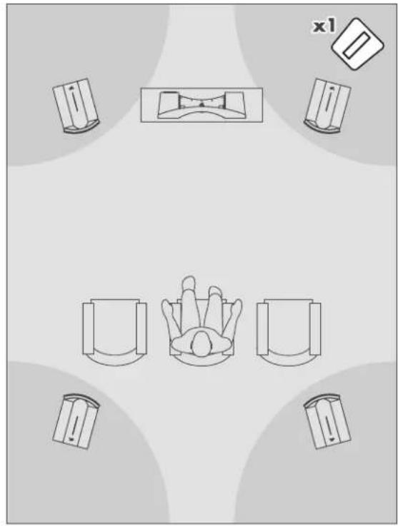
natural_image
Top-down view of a dining table with chairs, tables, and a table set (no text or symbols)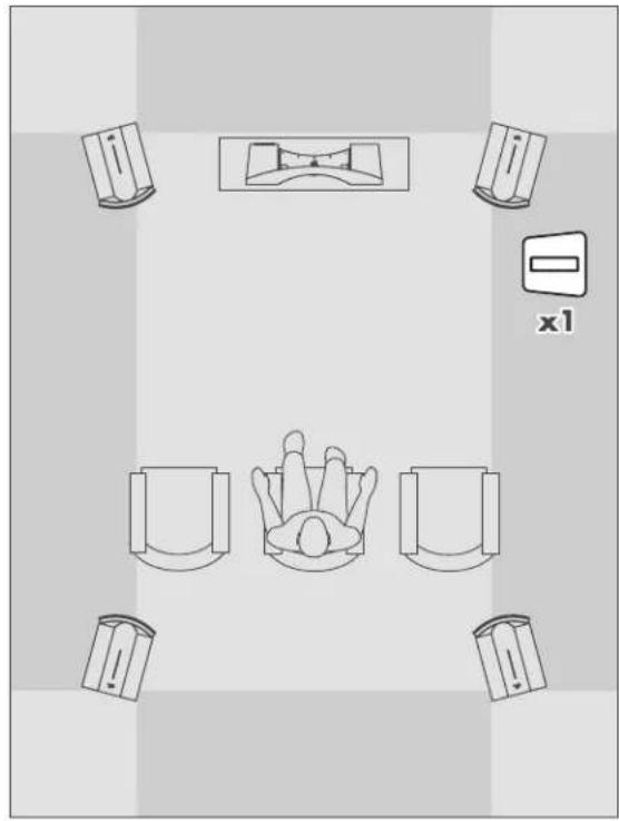
natural_image
Top-down view of a table with four chairs, a table set, and a monitor icon (no text or symbols)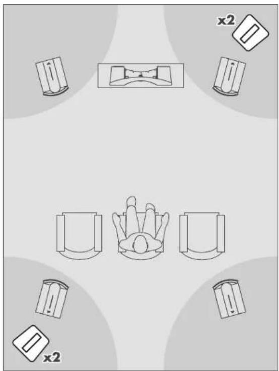
natural_image
Top-down view of a table with four chairs and six boxes arranged around it, no text or symbols present.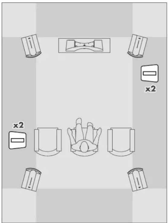
natural_image
Top-down view of a table with six items arranged around a central chair, no text or symbols visibleBALANCED FORCE™ [210]
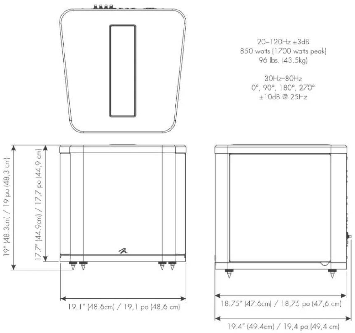
20-120Hz ±3dB
850 watts (1700 watts peak)
96 lbs. (43.5kg)
30Hz-80Hz
0°, 90°, 180°, 270°
±10dB @ 25Hz
BALANCED FORCE™ [212]
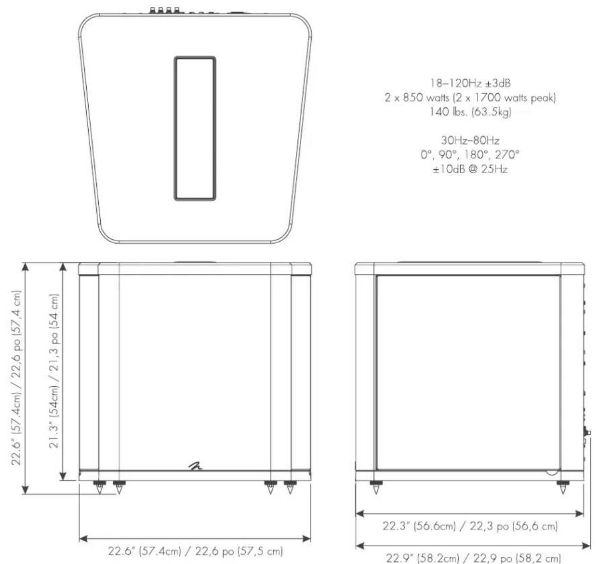
18-120Hz ±3dB
2 x 850 watts (2 x 1700 watts peak)
140 lbs. (63.5kg)
30Hz-80Hz
0°, 90°, 180°, 270°
±10dB @ 25Hz
22.6" (57.4cm) / 22,6 po (57,5 cm)
22.9" (58.2cm) / 22,9 po (58,2 cm)

MARTIN LOGAN®
lawrence, Kansas, USA tel/tél. 785.749.0133 fax/téléc. 785.749.5320 www.mortinlogan.com

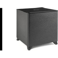
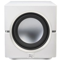
- BALANCED FORCE™ [210]
- BALANCED FORCE™ [212]
- IMPORTANT SAFETY INSTRUCTIONS
- Settings:
- A/V Processor Bass Management Settings:
- BalancedForce 210 & Balanced Force 212
- Step 1: Unpacking
- Step 2: Placement
- Step 3: Signal Connection
- Step 4: Power Connection (AC) (see warning)
- Step 5: Setting the Controls
- Step 6: Listen and Enjoy.
- Congratulations! You have invested in one of the world's premier subwoofers.
- Accessing the Control Panel
- Top Control Panel
- On/Off/Dim
- Level
- 25Hz Level (dB)
- Low-Pass Filter (Hz)
- Phase Control
- Mode
- Status Light
- Tone Sweep
- Room EQ
- Custom Low-Pass
- Rear Connection Panel
- USB Status Light (with Flash Drive Connected)
- USB Status Light (with PBK Connected)
- Power Status Light
- USB Input
- PBK Input
- Trigger Input (5V-24V DC)
- Left In / Right In (Balanced XLR)
- LFE In (Balanced XLR)
- Left In / Right In (Line Level)
- LFE In / Multi In (Line Level)
- Multi Out
- Left In / Right In (Speaker Level)
- Break-In
- AC Power Connection
- 2-Channel Mode
- (Line Level RCA or Balanced XLR)
- Signal Connection:
- Recommended Control Settings:
- Multi-Channel Mode
- Simultaneous 2-Channel/Multi-Channel Mode
- Using Speaker Level Inputs
- Loading a Custom Low-Pass Filter
- Updating Firmware
- PBK Room Correction
- Multi Out—Daisy Chaining Multiple Subwoofers
- Optional Wireless Connection
- Subwoofer Position
- Installing in a Cabinet
- Ask Your Dealer
- Solid Footing
- Enjoy Yourself
- Your Room
- Terminology
- Standing Waves
- Resonant Surfaces and Objects
- Resonant Cavities
- Front Left and Front Right
- Center Channel
- Surround/Effects Speakers
- Subwoofer
- BalancedForce™ For Cleaner Bass
- Proprietary Switching Amplifiers
- 25Hz Level Control
- PBK (Perfect Bass Kit)
- Optional Custom Low-Pass Filters
- Frequently Asked Questions
- Why won't my subwoofer read my USB flash drive when I attempt to add a custom low-pass filter or update my firmware?
- How do I clean my subwoofer?
- Is it safe to set things on my subwoofer?
- Is there likely to be any interaction between my subwoofer and the CRT television in my Audio/Video system?
- Will my electric bill go 'sky high' by leaving my subwoofer plugged in all the time?
- Should I unplug my sub during a thunderstorm?
- I disposed of my speaker's original packaging. Can I buy new packaging for my speaker?
- Troubleshooting
- No Output
- Muddy Bass
- Hums or Unusual Sounds
- Warranty and Registration
- Serial Number
- Service
- Contenu Introduction
- Right In/Left In (Balanced XLR)
- Right In/Left In (Line Level)
Brand : Martin Logan
Model : BalancedForce 210
Category : Subwoofer