Aerium HPC - Bike Cube - Free user manual and instructions
Find the device manual for free Aerium HPC Cube in PDF.

Frequently Asked Questions - Aerium HPC Cube
User questions about Aerium HPC Cube
0 question about this device. Answer the ones you know or ask your own.
Ask a new question about this device
Download the instructions for your Bike in PDF format for free! Find your manual Aerium HPC - Cube and take your electronic device back in hand. On this page are published all the documents necessary for the use of your device. Aerium HPC by Cube.
USER MANUAL Aerium HPC Cube
CUBE Super HPC, HPC + GTC
Twin Mold Technology
Additionaloperatinginstructions:
CubeCarbonframeSuperHPC,HPC+GTC
and(full)carbonforks

CUBE
SUPER HPC|HPC|GTC
3>GENERALNOTES
Important Notes!
CUBE Super HPC, HPC + GTC
This document must be read carefully prior to assembly and use of the frame/entire bike and should be observed accordingly.
These instructions are additional operating instructions for the Super HPC, HPC and GTC Series and (full) carbon forks. Please also observe the main Instruction Manual! If you do not have this please request it from the dealer.
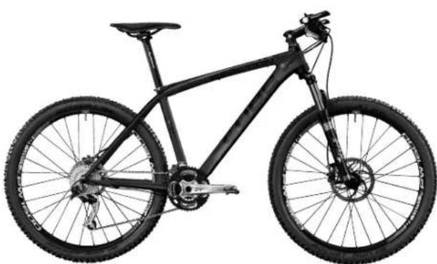
Picture 1: (top)
Cube Reaction GTC SL 2010
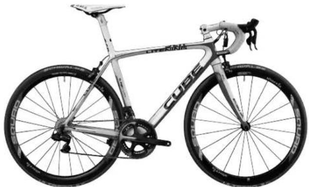
Picture 2: (bottom)
Cube Litening Super HPC Di2 2010
4
Table of Contents
- General Notes 3
-
Manufacturing process 4
2.1. Road racing 4
2.2. Seat clamp/seat post 4
2.3.DeraillLeur fitting. 5
2.4. Headset 5
2.5. Bottom bearing / crank inside bearing system 5
2.6.Rear assembly. 5
2.7.Dropouts 6
2.8.Battle holder inserts 6
2.9.Roller training. 6
2.10. Transportation 6 -
(Full) carbon forks
4.Care instructions 8 - Guarantee and special ex gratia settlements 8
- Liability 9
- Quality Assurance and rigidity testing 9
- Carbon Rigidity Test 10
- Assembly Instructions 11
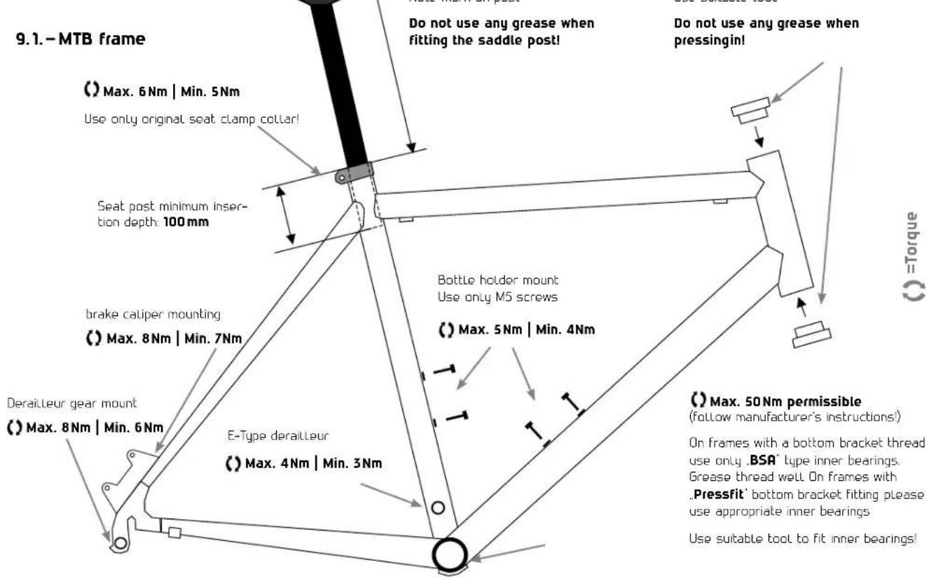
9.1.MTB frame 11
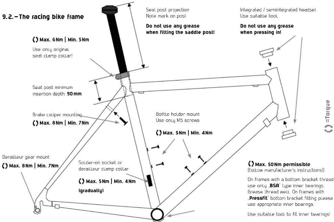
9.2. The racing bike frame 12
5>GENERALNOTES
1.-General Notes
Carbon frames and (full) carbon forks are lightweight construction components which are manufactured in several production steps using modern manufacturing procedures. The light weight is achieved mainly by using high-performance fibre composite materials in conjunction with an appropriate method of fibre construction.
Component safety and rigidity. In addition to low mass were important criteria in the design of the carbon frames and forks. Unavoidable irregularities in the fibre orientation arising during manual procedures and small air inclusions in the resin coating layer or surface unevennesses are purely visual in nature and have no influence on the quality and performance of the frame. Differences in finish and "blemishes" do not constitute grounds for complaint.
Our carbon frames and integral (full) carbon forks are approved for a maximum rider weight of 115 kg system weight (rider + complete bike + luggage). Loadings deviating from the purpose of use intended (e.g. jumps) may lead to damage and constitute a risk to the user. We accept no liability for damage arising from improper use.
It is not permissible to fit additional components to any frame or fork tubing which is attached by means of clamping to the tubing in question. Undefined stresses in the circumferential direction of the tubing considerable can occur in this way which may cause damage and which may drastically reduce the service life, and may also lead to a risk to the safety of the user.
Basically every frame including forks must be given a thorough examination at regular intervals in respect of damage (e.g. cracks, visible delamination, discolouration etc). Shock and impact stresses may cause damage not visible externally such as delamination (separation of fibres from the surrounding
plastic matrix) in the bottom Laminate layers causing a drastic reduction in performance and consequently safety as well. After any accident, crash or other defined or uncontrolled mechanical stresses the frame and forks must not be ridden for reasons of safety and should be sent to us for examination (see also Guarantee).
With regard to accessories used the instructions for use and user guide provided by the manufacturer concerned must be followed!
6 MANUFACTURINGPROCESS
2.-Manufacturing process
Monocaque
Twin Mold Technology
In this process any folding jeopardising the safety of the product is eliminated by continuous monitoring of the carbon fibres during the curing process. By additionally using rigid inner formers at intersection points the proportion of resin is considerably reduced and the fibres bonded more tightly one to another. The result is increased product safety and improved rigidity levels.
Advanced Twin Mold
In this process any folding endangering the safety of the product is eliminated by continuous monitoring of the carbon fibres during the heat curing process. This is guaranteed by an inner former which gives the perfect frame shape earlier in the layup process. Hence every individual fibre remains in its exact position during the curing process. This method of manufacture makes it possible to increase the carbon fibre content within the frame structure to match
the design stresses. The increased composite content means that for the same stability there is less weight in the form of resin and that the frame has greater rigidity for less weight. The positive side-effect of this method of manufacture - perfect processing.
2.1.-Road racing
Our frames are designed for extreme riding stresses. However during road racing stresses greater than those occurring during actual riding may arise as a result of collusion with objects or other riders. These stresses cannot possibly be foreseen and allowed for in the construction and design of a frame or forks. We therefore accept no liability for any damage resulting from use other than that intended. Frame and forks must be examined particularly carefully for damage (e.g. cracks, delamination, discolouration etc.) before and after each instance of use in racing. After serious crashes or accidents the frame and forks must not be ridden. The surface of the frame and forks must not be damaged. This includes indentations and Large deep scratches which
penetrate beyond the first clear coat of Lacquer. In case of doubt the frame and forks must be sent in for checking.
2.2.-Seat clamp/seat post
When tightening the seat clamp bolt (see Diag. 1) a maximum torque of 6Nm must not be exceeded. (min. 5Nm ). Sead post and seat tube must not be greased! Only seat posts with the correct external diameter may be used. Seat posts of any other diameter must not be ridden. The seat tube must not be filed out or mechanically modified in any other manner. The maximum permitted seat post extension (measured from the upper edge of the seat tube to the upper edge of the seat post) is 270mm . The minimum insertion depth for the seat post is 100mm (see pages 11/12)
Racing bike frames are designed for either a solder-on socket derailLeur mounting or for a classic derailLeur clamp fitting with a 34.9mm clamp - MTB frames have either a classic 34.9mm derailleur clamp or an E-type derailleur
MANUFACTURINGPROCESS
fitting. No other derailLeur mountings maybeused.
Maximum torque for fitting the derail-leur clamp collar on the seat tube is 4Nm and must be fitted in intermediate steps. When fitting a torque wrench it is important to avoid deformation of the seat tube in the vicinity of the clamp.
Damage to the seat tube in the vicinity of the deraillaur clamp by excessive tightening or incorrect size of clamp collar may lead to safety-related deformation and damage and must be avoided.
2.4.-Headset
Fully or semi-integrated headsets are used in carbon frames for optimum rigidity values and optimum distribution of forces and high levels of security.
Unauthorised milling work is not permissible and will result in the guarantee being invalidated.
Delivery is with headset installed. Any change of headset must be agreed with
the manufacturing company. Pressfitting the headset shell bearings must be performed using a specially designed tool. Press fitting must be performed with caution and it must be ensured that the shell bearings do not twist. The shell bearings must not be greased at points where they are in contact with the frame. The side facing the bearing should be greased to ensure Long life of the headset
2.5.-Bottom bearing / crank inside bearing system
The bottom bearing must be fitted using a tool specially designed for the task. Only bottom bearing and crank inside bearing systems designed for "BSR" or "Pressfit" types may be used. The inner bearing thread should be rethreaded with a suitable threading die and be thoroughly greased. When fitting the inner bearing it must be ensured that on the right hand side seen from the direction of travel there is a left-hand thread in the bottom bracket (the inner bearing element is screwed in anticlockwise). On the left side seen from the direction of travel the bottom bracket bush has
a right-hand thread (the inner bearing element is screwed in clockwise). The torque stipulated by the relevant manufacturer should be observed and the maximum inner bearing torque is 50Nm (min. 45Nm) (see Pages 11/12). The Press-fit inner bearing must only be press-fitted using the tool specially designed for the purpose.
2.6.-Rear assembly.
Your carbon frame rear assembly has been designed and built for a hub width of 130mm (racing bike) and 135mm (MTB Hardtail) and 135/142mm (MTB-Fully).
On the rear assembly only hubs of 130mm (racing bike) and 135mm (MTB-hardtail) and a quick-release mechanism must be used. For the Fully models 135mm a quick-release mechanism and a 142mm Syntace X12 axle.
The use of hubs with other dimensions and/or without quick-release mechanism may result in stress and distension conditions, which can lead to serious damage and therefore present a risk to safety. The rear assembly is designed
8 MANUFACTURINGPROCESS
for standard racing bike brakes (or disc brakes in the case of the MTB). The maximum permissible torque when fitting brakes is 8Nm (min. 7Nm). The maximum permissible rear wheel disc size for the carbon hardtail frame is 160 mm and that for the carbon Fully frame is 180 mm or 160 mm for the AMS Super HPC.
2.7-Dropout
The maximum torque for fitting the gears to the derailleur hanger is 8Nm (min. 7Nm (see Pages 11/12).
2.8.-Bottle holder inserts
The threaded inserts on your carbon frame are designed for fixing standard bottle holders with an M5 thread and other thread sizes are impermissible. The maximum torque of bottle holder fixing screws is 5Nm (min. 4Nm) (see Pages 11/12). Carbon frames are approved for bottle holders which can take a 750ml capacity bottle.
2.9.-Roller training.
Your carbon frame is a high-performance lightweight assembly.

The carbon frame must NOT be used for roller training on so-called fixed rollers (Tacx, Elite, etc.).
The fixed loading of the dropouts and quick-release axle differs greatly from the stress occurring during riding and can lead to damage in the vicinity of the dropouts/rear assembly.
Use on a Loose roller without any fixed tensioning of the frame is permissible.
2.10.-Transportation
When transporting your carbon frame and (full) carbon forks particular care is required, as this can give rise to stresses which never occur when riding and which could therefore damage your frame. The following should therefore be noted:

Transporting your carbon frame with carrier systems which use clamping elements for fixing and retaining the frame tubes is impermissible as the clamping forces of the fixing elements can cause damage to the frame/forks tubing

During transportation do not place any objects on the frame and forks and stow so that they cannot slip.

When transporting with the front or rear wheel removed it is recommended that a distance piece is inserted instead of the hub in the rear assembly (racing bike 130mm, MTB 135mm) and in the forks (100mm) in order to prevent damage.

When travelling by air or on journeys where the "bicycle" luggage item is not checked with regard to damage-free stowage, adequate protection of the frame and forks must be ensured (e.g. by using suitable hard-top cases etc.)
9(FULLCARBONFORKS
3.-(full) carbon forks
The (full) carbon forks which are installed as well as carbon forks with a upper shaft part made out of aluminium are forks with a tapered steerer. This has an external diameter of 1.5^ in the area of the lower control bearing and tapers towards the top to the clamping area of the handlebar stem to 118^ . Only handlebar stems and headsets compatible with this shaft diameter may be used and which are approved by the bike manufacturer.
If the headset bearing lower cone ring is driven into the bearing seat with massive force there is a danger of damaging the forks. Fitting a headset must be carried out by a specialist technician. The shaft tube external diameter in the vicinity of the stem is designed for front extensions with a clamp diameter of 11/8" . Only the handlebar stems with corresponding internal dimensions and cleanly finished interior surfaces may be used. The fitted stem may project no more than a
maximum of 2mmabove the edge of the shaft tube end.
The front brake is fitted to the forks using the special screws supplied by the manufacturer with an M6 thread with an internal hexagon (RUlen screw) head. (SW 5mm). The external diameter of the nuts must not exceed 8mm and the maximum torque of the nuts is 8Nm (min.7Nm)
For carbon forks with a upper shaft part made out of aluminium so-called "ahead claws" be driven in to adjust the control bearing. Under no circumstances may this be done for a (full) carbon fork. The supplied insert for internal clamping should always be used to do that or the screw insert for models with an internal thread used in the carbon shaft. Use of the "ahead claws" (full) carbon forks can cause considerable damage to the shaft tube and dangerous total failure of the assembly may even occur! The shaft length must only be adjusted or modified by a specialist technician.
Ideally a metal saw with low abrasion rate or a metal circular saw with a diamond saw blade and water cooling should be used. In the event of dry trimming adequate protection from dust inhalation produced should be ensured. Inhalation protection with a fine dust filter and safety glasses are recommended.
4. - Care instructions
Your carbon frame and your (full) carbon forks should be cleaned regularly. Ordinary paint care products with or without silicon additive and cold to Lukewarm water to which may be added ordinary detergent may be used. To be avoided are solvents of any description, alcohols (e.g. ethanol or isopropanol), hot water with alkaline additives or cleaning with steam jets and pressure washers.
5.-Guarantee and special ex gratia settlements
Services under the guarantee are provided only in the event of faulty materials or manufacture and never in the event of fatigue or overload stress damage. We provide a two-year guarantee on our frames and forks and we also offer special ex gratia services.

If you discover damage to your frame and/or forks you may send the damaged frame and/or forks to us for assessment and an estimate of possible repair costs via your dealer

Transport costs in every case are borne by the customer. Following assessment of repair costs the repair is carried out either free of charge or you will receive an advance estimate of repair costs due (see CCR Service).

The decision as to whether a repair is to be carried out free of charge rests solely with the manufacturing company and in no circumstances is there any claim to cost-free repair.

The special ex gratia provisions only apply to the first owner

Only cleaned frames or forks are accepted for guarantee work!
In the event of frame or fork complaint claims we reserve the right to apply a reduction in value based on the duration of use.

The guarantee is rendered invalid in the case of damage, which is attributable to incorrect assembly, misuse, unauthorised modifications or mechanical working of frames and fork components (drilling, milling, filing, sawing etc, on frames or forks manufactured by us. The final decision as to what extent a claim under the guarantee exists is a matter for the management of the manufacturing company.
7>LIABILITY
6. - Liability
The manufacturing company accepts no liability for accident damage or consequential loss. The user bears the risk in the event of personal injury and material damage. The manufacturing company accepts no liability for damage or accidents caused by improper use of the frame and failure to comply with the stipulations indicated here
Quality Assurance and rigidity testing

Every carbon frame ready for delivery and every set of (full) carbon forks are subjected to a rigidity test. For each frame height and each set of forks a rigidity tolerance range is defined in preliminary testing. Only frames and forks which come within this tolerance range leave the factory.
The rigidity test is used as a Quality Assurance measure and is performed on the company's own test rig. To do this the frame to be measured is fixed in place at the rear assembly and the
steering tube. Then the gear crank area is deflected to one side using a defined force delivered by a pneumatic cylinder. As a second step rigidity measurement of the steering pipe occurs through targeted torsion of the steering head to the frame. The rigidity values arise from the ratio of the applied force and the resulting deflection of the frame area and are documented on the test sticker in the operating instructions enclosed.
12>CARBONRIGIDITYTEST
7. - Carbon Rigidity Test
The following data are of importance for any possible guarantee or warranty claims in the event of an exchange frame in the context of our Crash Replacement Program. Please keep the datasheet in a safe place.
Frame or (full) carbon forks measurement result:
13>ASSEMBLYINSTRUCTIONS
9. - Assembly Instructions
14ASSEMBLYINSTRUCTIONS
CUBE Super HPC, HPC + GTC
9FOURCHESENCARBONEETTOUTCARBONE
2.10.-Transport
CUBE Super HPC, HPC + GTC
CUBE Super HPC, HPC + GTC
Twin Mold Technology