PX - Surveillance Camera Guardall - Free user manual and instructions
Find the device manual for free PX Guardall in PDF.

User questions about PX Guardall
0 question about this device. Answer the ones you know or ask your own.
Ask a new question about this device
Download the instructions for your Surveillance Camera in PDF format for free! Find your manual PX - Guardall and take your electronic device back in hand. On this page are published all the documents necessary for the use of your device. PX by Guardall.
USER MANUAL PX Guardall
The installation manual provides the information essential for wiring and operating the system. Copies of the engineer manual, and all other Guardall manuals, can be downloaded from the Guardall web site, at
www.guardall.com
The documentation section of the Guardall web site is password protected, and you may have to apply for access using the on-line form provided on the site.
This manual and the PX/QX/RX systems described in it are copyrighted, with all rights reserved. This manual may not be copied except as expressly permitted in writing by Guardall. Export of this technology may be controlled by the U.S. Government. Diversion contrary to U.S. Law prohibited.
R&TTE Directive Declaration
C€
Hereby, Guardall declares that the RX16i, QX32i, PX48i, PX80i and the PX250i are in compliance with the essential requirements and other relevant provisions of the RTTE Directive 1999/5/EC.
If you have any doubts concerning the suitability, connection or uses of this apparatus then consult a suitably qualified person before continuing.
SUITABILITY FOR USE
The apparatus has been designed to work on all European analogue networks It provides the following facilities:
- Automatic Call Initiation.
- Series connection.
- Dial tone Detection
- Automatic dialling using DTMF tones.
- Automatic Call Answering.
-
Stored number dialling.
-
Alarm transmission and transmission/reception of configuration data.
It is not suitable for connection to PABX systems or for use as an extension to a payphone.
The full Declaration of Conformity for is available each product from Guardall by contacting the Customer Support Department.
EMC & LV Directives Declaration
CE
Apart from those products required to comply with the RTTE Directive, the remaining products described in this manual comply with the essential requirements and provisions of the EMC Directive 2004/108/EC and the LV Directive 2006/95/EC, based on application of the EU harmonised standards listed below. To comply with the directives it is essential to adhere to the installation recommendations contained in this document.
The full Declaration of Conformity for is available each product from Guardall by contacting the Customer Support Department.
Proximity R&TTE Declaration
CE!
The Proximity Reader and the Keypad (with integral proximity token reader) are in compliance with the essential requirements and other relevant provisions of Directive 1999/5/EC. Whilst it operates on a non-harmonised frequency of 125KHz, it meets all relevant harmonised standards. It has been notified in the following EU countries: Belgium, Italy, France, The Netherlands, Denmark, Finland, UK, Ireland, Germany, Spain, Portugal, Norway, Greece and Sweden.
EN50131 & PD6662 Grades
PX control panels are suitable for use in systems designed to comply with EN50131 and PD6662:2010. The grade and environmental class of each variant is shown in the table.
| Variant Grade Class | ||
| RX16i, QX32i 2 II | ||
| PX48i, PX80i, PX250i, PX500, PX250HS 2 or 3 (Programmable) II |
Refer to the reset options in the engineer programming manual for details on programming the EN grade.
Mains
As the system uses hazardous voltages it is recommended that the mains supply connection follows national wiring rules and is carried out by a suitably qualified person. This equipment must be permanently connected to a mains fused spur (3A or 5A) using double insulated 3-core cable with each core being no less than 0.75mm^2 (18AWG). The mains cable should be clamped securely with the cable clamps provided within the equipment/installation kit and the insulation around the inner cores shall not touch the case when they are inserted into the mains terminal block. Knockouts are provided on the top, bottom and sides of this equipment and these are intended for conduit or cable glands. As a mains switch is not provided on the equipment, a readily accessible disconnect device shall be incorporated in the building installation wiring. Where there is doubt as to the phase of this wiring, the device, when operated, will disconnect both poles simultaneously.
| Item RX16i/ | QX32i | PX48i/PX80i/PX250i | PX500/PX250HS | 3A Smart Concentrator | Smart Access Module |
| External power source 230VAC +/- 10%, 50Hz | |||||
| Input current rating (AC) | 140mA | 220mA | 320mA | 330mA | 160mA |
| Mains Fuse F315mA 250V | F400mA 250V T630mA 250V | T630mA 250V F400mA 250V | |||
Battery Disposal
It is the responsibility of the installer to dispose of batteries according to the local laws and regulations of their region. Contact your local waste management office for information on battery recycling or disposal.
If you are not able to identify the applicable rules in your area, please check the instructions which will be available from the battery manufacturer.
AUX DC Supply
AUX DC Supply
Technical Information
The DC supply output is a Safety Extra-Low Voltage (SELV) circuit. This DC supply rating is for all the DC current requirements, including recharging the battery. The supply has the following rating:
| Item RX16i/ | QX32i | PX48i/PX80i/PX250i | PX500/PX250HS | 3A Smart Concentrator | Smart Access Module |
| Output voltage (DC) | 13.7V ± 5% | 14V ± 5% | 14V ± 5% | 14V ± 5% | 14V ± 5% |
| Standby Battery 7Ah 7Ah, | 18 Ah | 7Ah or 18Ah | 2 off 18Ah 7Ah, | ||
| Maximum recharge time 24 hours 24 hours 24 hours 24 hours | |||||
| Power supply rating 1.0A | 1.5A | 2.5A | 3.0A | 1.5A | |
| Battery Charge Limit | 0.5A | 0.75A | 0.78A | 0.9A per battery | 0.75A |
| Aux1 DC supply Fuse F800mA 250V | F800mA 250V | F800mA 250V | F800mA 250V | F1.6A 250V | F800mA 250V |
| Aux2 DC supply Fuse | F800mA 250V | F800mA 250V | F800mA 250V | F1.6A 250V | F800mA 250V |
| XiB Bus DC supply | F800mA 250V (Fuse 4) | F800mA 250V (Fuse 6) | F800mA 250V (Fuses 5,6,7,8) | F800mA 250V (Fuse 5) | |
| Battery | F2.5A 250V (Fuse 2) | F2.5A 250V (Fuse 4) | F2.5A 250V (Fuse 9) | F2.5A 250V (Fuses 3 & 4) | F2.5A 250V (Fuse 4) |
| Sounder/Audio/Aux. DC | F800mA 250V (Fuse 4) | F800mA 250V (Fuse 3) | F800mA 250V (Fuses 3 & 4) | ||
All wiring in this enclosure is required to be V-2, IEC approved or PVC type. All installation wiring within this equipment should utilise plastic cable ties to bundle cables so as to provide strain relief for the cable.
AUX DC Supply
EN 50131-6 Compliance
EN 50131-6 Technical Data
| Item | RX16i/QX32i | PX48i/PX80i/PX250i | PX500/PX250HS | 3A Smart Concentrator |
| Power Supply | Type A | |||
| Battery Type | Maintenance Free 12V Lead Acid | |||
| Rated Output voltage | 13.7Vdc ± 5% | 14Vdc ± 5% | 14Vdc ± 5% | 14Vdc ± 5% |
| Quiescent Current | 80mA 110mA | 110mA 130mA | ||
| Maximum Rated Output* | 0.42A | 0.49A | 0.49A | 1.07A |
| Max Peak to Peak Ripple Voltage | 0.7V | 0.7V | 0.7V | 0.1V |
| Over-voltage protection trigger voltage | <+18.4V | <+18.4V | ||
| Maximum Power Output | +14.4Vdc | +14.7Vdc | +14.7Vdc | +14.7Vdc |
| Minimum Power Output | +11.4Vdc | +11.4Vdc | +11.4Vdc | +11.4Vdc |
| Battery Low Voltage Point | +11.4Vdc | +11.4Vdc | +11.4Vdc | +11.4Vdc |
| Low Output Voltage (Power Fail Point) | +10.7Vdc | +10.7Vdc | +10.7Vdc | |
| Deep Discharge Threshold | <10.6Vdc | <10.6Vdc | <10.6Vdc | |
*Ratings to meet EN 50131-1 – see Battery Standby Section for further details
Getting Started
In this manual you will learn how to;
• Identify the components of the PX system
- Connect components together
• Make simple configuration changes
If you are new to the system it is recommended that you connect a basic system “on the bench” and familiarise yourself with programming the panel. Before getting started ensure you have the following components;
- A control panel
- A LCD keypad
- A few meters of 4 core cable
• A concentrator (optional)
Now follow these simple steps:
- Connect +, -, A and B terminals of the keypad (CN6-XiB) to the panel XiB (refer to the appropriate diagram in the panel section of this manual for details) using a length of 4 core cable. For simplicity of wiring adhere to the following colour coding;
- Red
-
Black
A Yellow
B Blue -
Set the address of the concentrator to address 1 (DIL switches 1-6 all off (0))
- Connect +, -, A and B terminals of the concentrator (CN2-XiB) to the panel XiB connector using a length of 4 core cable using the same colour coding as used for the keypad connections.
- Connect the mains cable to the fused terminal block and apply power.
The keypad address must be set before it can be used on the system. To set the keypad address, open the case so that the case tamper switch is activated. Press and hold the ? button until the address prompt is displayed (approximately 4 seconds):
Address = ?? √ or x
If the keypad has not been addressed then the prompt will be ?? or 99. Press X to exit address mode without change.
Address = 01 √ or x
Press 01 to set the keypad address to 1, then press √to confirm
00:00 Sat 02 Jan Guardall
The keypad will then display the time/date and company name.
PX KP Type-n Version 2.00
If the displayed message is as shown, or no bleep is heard, then the keypad is not responding so check the bus connections.
The keypad types are:
| Description Type | |
| Standard or with proximity reader 1 | |
| With 2 EOL circuit inputs 2 |
Once the keypad is replying then enter the default engineer PIN code, 9999, remembering to validate the PIN code by pressing √.
00:00 Sat 02 Jan Enter-*****
The PIN code digits are displayed as “*” characters.
Order Codes
| Order Code | Description |
| W76469 | RX16i Control panel (English) |
| W76468 | RX16i Control panel (Chubb) |
| W76471 | RX16i Control panel (Chubb) and Visonic Rx |
| W76698 | RX16i Control Panel (Chubb) Kit, with Standard LCD Keypad |
| W76673 | RX16i Control Panel (Chubb) Kit, with Prox LCD Keypad |
| W76674 | RX16i Control Panel (Chubb) Kit, with Prox LCD Keypad and Visonic Rx |
| W76481 | QX32i Control panel Metal (English) |
| W76476 | QX32i Control panel Plastic (English) |
| W76651 | QX32i Control panel (Chubb) |
| W76675 | QX32i Control Panel (Chubb) Kit, with Prox LCD Keypad |
| W76740 | PX48i V5 Control panel (English) |
| W76759 | PX48i V5 Control panel (Chubb) Kit with Prox LCD Keypad |
| W76742 | PX80i V5 Control panel (English) |
| W76743 | PX500 V5 Control panel (English) |
| W76760 | PX500 V5 Control panel (Chubb) Kit with PSTN Module and Prox LCD Keypad |
| W76744 | PX250HS V5 High Security Control panel (English) |
| W76756 | PX250HS V5 High Security Control panel (Chubb) |
| W76247 | LCD Keypad 2 Line, 2 EOL circuits |
| W76250 | LCD Keypad 2 Line, Proximity & 2 EOL circuits |
| W76251 | LCD Keypad 2 Line, 2 EOL circuits (Chubb) |
| W76254 | LCD Keypad 2 Line, Proximity & 2 EOL circuits (Chubb) |
| W73821 | Proximity Reader |
| W73820 | Proximity Fob Pack (2 off) |
| W73837 | Proximity Card Pack (10 off) |
| W76512 | Output Module (8 Relay/8 Transistor) |
| W76068 | Serial Module (RS232) |
| W74424 | RS232 Direct Connection Cable |
| W73534 | EU GuardStationTM Modem |
| W76546 | Programming Kit |
| W73822 | Access Module |
| W73847 | Smart Access Module |
| W74368 | Data Comms Module (External) |
| W74369 | Data Comms Module (Internal) |
| W76727 | GSR Security |
| W76278 | GSR Access |
| W76279 | GSR Security + Access |
| W76010 | GSR Direct |
| W76667 | GSR Basic |
| Order Code | Description |
| W76287 | Diagnostic Concentrator 4 Input/2 Output (Plastic) |
| W74480 | Diagnostic Concentrator 8 Input/4 Output (Plastic) |
| W74481 | Universal 4 relay output board |
| W76757 | 3A Smart Concentrator V5 (8 input/4 output) |
| W76758 | Chubb 3A Smart Concentrator V5 (8 input/4 output) |
| W76110 | Radio Module (Visonic) |
| W76067 | Radio Module (Inovonics) |
| W76069 | Dual Comm Module |
| W76070 | PSTN Module |
| W76071 | GSM Module |
| W76050 | Speech module |
Order Codes
Inovonics
| Order code | Inovonics Part No. | Description |
| W76067 | Radio module | Inovonics(serial module + EE4000) |
| W76245 | EE5000 | Inovonics repeater |
| W76099 | EE1215 | Universal (Generic) Transmitter with case tamper (SAME AS EE1210 BUT WITH OTW TAMPER) |
| W76094 | EE1216 | Universal (Generic) Transmitter w/Wall Tamper (SAME AS EE1215 BUT WITH DUAL INPUT) |
| W76101 | EE1233S Pendant | Sgl. Button |
| W76095 | EE1233D Pendant | Dbl. Button |
| W76241 | EE1223S 1 button | water resistant pendant TX |
| W76242 | EE1223D 2 button | water resistant pendant TX |
| W76102 | EE1235S Beltclip | Trans. Sgl Button |
| W76096 | EE1235D Beltclip | Trans. Dbl Button |
| W76292 | EE1238D Dual condition | 2 button belt clip TX |
| W76669 | EE1261 | Inovonics PIR (EN Grade 2 18m PIR) Replacement for W76103) |
| W76594 | EE1265 Inovonics | 360 deg PIR |
| W76097 | EE1247 | ShatterPro/Transmitter |
| W76098 | EE1242 | Smoke detector |
Order Codes
Visonic
The following Visonic transmitter types have been tested with the system but are not available to purchase from Guardall.
| Part Number Type | Description | |
| MCT-234 | 4-Button | Keyfob |
| MCT-101 1-Button | Control Fob | |
| MCT-102 2-Button | Control Fob | |
| MCT-104 4-Button | Control Fob | |
| Next+ PIR MCW Motion Detector (PIR) | ||
| MCT-302 | Door/Window | Contac |
| MCT-501 | Glassbreak | Detector |
| MCT-100 | Universal | Transmitter |
| MCPIR-3000 Motion Detector (PIR) | ||
| MCT-241 | Pendant | |
| MCT-220 | Emergency | Button |
| MCT-124 Twin Button Control Fob | ||
| MCT-425 | Smoke | Detector |
| MCT-550 | Flood | Detector |
| MCT-442 Carbon Monoxide Detector | ||
| MCX-600 | Repeater | Module |
System Components
A system comprises of the following components:
- A control unit, which processes all the alarm information from the detection points. Outputs are provided to operate sounders, strobe and communication devices. Configuration information is stored in EEPROM. The manual details the features of the control panels. Most features in the PX panel range are common. The differences are shown in the table.
| Feature | RX16i | QX32i | PX48i | PX80i | PX250i | PX500 | PX250HS |
| Circuits 16 | 32 | 48 | 80 | 250 | 512 | 256 | |
| Concentrators | 2 | 6 | 10 | 18 | 32 | 64 | |
| Radio Modules | 2 | 2 | 4 | 8 | 8 | 16 | |
| Radio Transmitters | 16 | 16 | 24 | 40 | 24 | 128 | 12 |
| Radio Keyfobs | 4 | 8 | 12 | 16 | 16 | 20 | |
| DVRs | 1 | 2 | 8 | 8 | 8 | 8 | |
| XiB Detectors | 8 | 16 | 24 | 40 | 40 | 64 | |
| Security Users | 16 | 32 | 50 | 100 | 250 | ||
| Areas | 4 | 8 | 8 | 16 | 24 | ||
| Set Groups | 4 | 8 | 8 | 16 | 32 | ||
| Sub Systems | 4 | 4 | 8 | 8 | 16 | ||
| Keypads | 4 | 8 | 8 | 16 | 24 | ||
| Event Log Size | 250 | 500 | 1000 | 1000 | 1000 | 1000 | 2000 |
| Output Modules | 1 | 2 | 8 | 16 | 16 | ||
| Output functions | 16 | 16 | 20 | 64 | 128 | 128 | 128 |
| Custom Responses | 2 | 5 | 5 | 10 | 10 | ||
| Tel Numbers | 8 | 8 | 8 | 8 | 8 | 8 | |
| Schedules | 2 | 4 | 32 | 32 | 32 | 32 | |
| HS Schedules | 16 | ||||||
| Custom users | 20 | ||||||
| Holidays | 14 | 14 | 14 | 14 | 14 | ||
| Max. Access Users | 1000 | 1000 | 1000 | 1000 | 1000 | ||
| Access Modules | 32 | 32 | 32 | 32 | 32 | ||
| Access Log Size | 1000 | 1000 | 1000 | 1000 | 1000 | ||
| GSR | 1 | 2 | 4 | 4 | 4 | 4 |
8
3
32
32
8
32
32
20
[Non-Text]
[Non-Text]
20
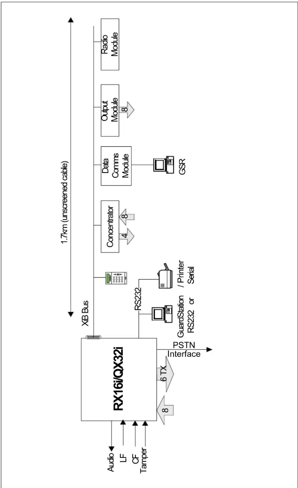
The diagram on the following page shows the bus peripheral connections.
- User interaction with the system is via LCD keypad. There must be at least 1 keypad on a system. There are several types of LCD keypad available, which are detailed later.
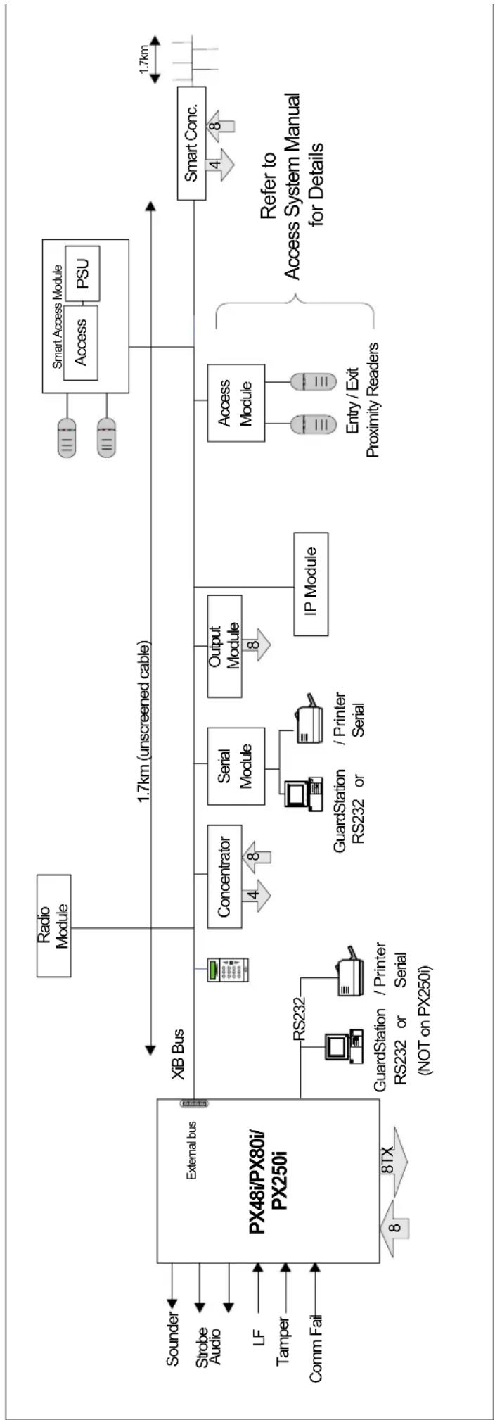
- On the RX16i, QX32i, PX48i, PX80i and PX250i, up to 8 detectors may be connected directly to the panel. Further detectors, up to the control panel limit, may be connected to the system through concentrators on a 4-wire bus. Each concentrator provides 8 additional circuits.
-
Optional equipment includes;
-
A dialler/modem/Dual comm module
- Output modules each with 8 programmable outputs
- A serial module for connection of a printer or PC
- Bus isolator
- Access module
- Data comms module for an Ethernet connection to a PC
- Radio module
- Audio module
Technical Specification
RX16i/QX32i Bus Connections
flowchart
graph LR
    A["Audio"] --> B["RX16i/QX32i"]
    C["LF"] --> B
    D["CF"] --> B
    E["Tamper"] --> B
    B --> F["XIB Bus"]
    F --> G["Concentrator"]
    G --> H["Data Comms Module"]
    H --> I["Output Module"]
    I --> J["Radio Module"]
    B --> K["RS232"]
    K --> L["GuardStation RS232 or / Printer Serial"]
    L --> M["GSR"]
    B --> N["Interface"]
    N --> O["8"]
    N --> P["6 TX"]
    P --> Q["PSTN"]
    style B fill:#f9f,stroke:#333
    style F fill:#ccf,stroke:#333
    style G fill:#cfc,stroke:#333
    style H fill:#fcc,stroke:#333
    style I fill:#cff,stroke:#333
    style J fill:#ffc,stroke:#333
Technical Specification
PX48i/PX80i/PX250i Bus Connections
Technical Specification PX48i/PX80i/PX250i Bus Connections
flowchart
graph LR
    A["External bus PX48i/PX80i/PX250i"] --> B["XIB Bus"]
    B --> C["Radio Module"]
    B --> D["Concentrator"]
    B --> E["Serial Module"]
    B --> F["Output Module"]
    B --> G["IP Module"]
    B --> H["Access Module"]
    H --> I["Entry / Exit Proximity Readers"]
    I --> J["Smart Access Module"]
    J --> K["Access"]
    J --> L["PSU"]
    M["Sounder"] --> N["External bus"]
    O["Strobe Audio"] --> N
    P["LF"] --> N
    Q["Tamper"] --> N
    R["Comm Fail"] --> N
    S["RS232"] --> T["GuardStation / Printer Serial (NOT on PX250i)"]
    T --> U["RS232 or / Printer Serial"]
    V["Concentrator"] --> W["4"]
    W --> X["8"]
    Y["Serial Module"] --> Z["GuardStation or / Printer Serial"]
    Z --> AA["8"]
    AB["Output Module"] --> AC["8"]
    AD["IP Module"] --> AE["8"]
    AF["Access Module"] --> AG["Entry / Exit Proximity Readers"]
    AH["Smart Conc."] --> AI["1.7km (unscreened cable)"]
    AI --> AJ["1.7km"]
    AK["Refer to Access System Manual for Details"]
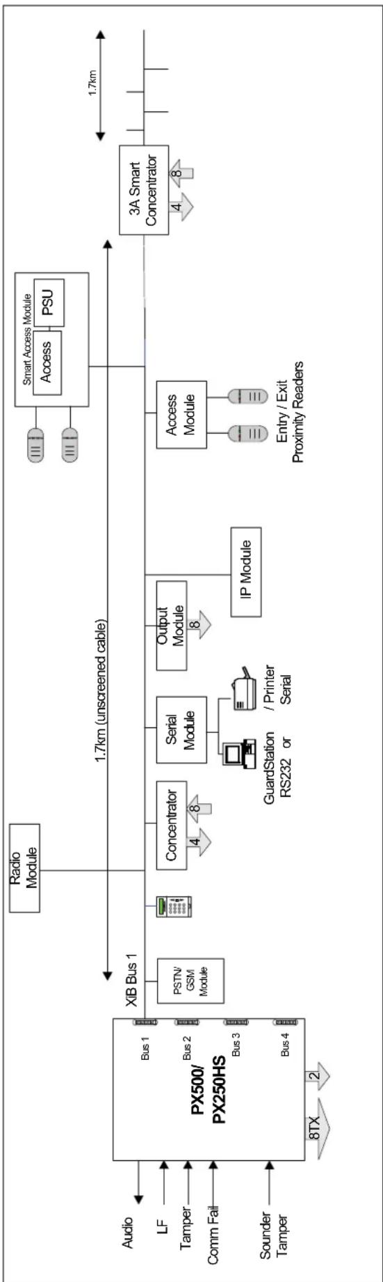
Technical Specification
PX500/PX250HS Bus Connections
flowchart
graph LR
    A["Audio"] --> B["Bus 1"]
    C["LF"] --> D["Bus 2"]
    E["Tamper"] --> F["Bus 3"]
    G["Comm Fail"] --> H["Bus 4"]
    I["Sounder Tamper"] --> J["Bus 1"]
    K["Audio"] --> L["Bus 1"]
    M["PSTN/GSM Module"] --> N["Concentrator"]
    O["Radio Module"] --> P["1.7km (unscreened cable)"]
    Q["Serial Module"] --> R["GuardStation or / Printer Serial"]
    S["Output Module"] --> T["IP Module"]
    U["Access Module"] --> V["Entry/Exit Proximity Readers"]
    W["Smart Access Module"] --> X["Access PSU"]
    Y["3A Smart Concentrator"] --> Z["1.7km"]
    style A fill:#f9f,stroke:#333
    style C fill:#f9f,stroke:#333
    style I fill:#f9f,stroke:#333
    style M fill:#f9f,stroke:#333
    style K fill:#f9f,stroke:#333
    style O fill:#f9f,stroke:#333
    style Q fill:#f9f,stroke:#333
    style U fill:#f9f,stroke:#333
    style W fill:#f9f,stroke:#333
    style Y fill:#f9f,stroke:#333
    style Z fill:#f9f,stroke:#333
Technical Specification
Technical Specification
Environmental
| Parameter Range | |
| Temperature range -10 to 50 °C | |
| Humidity 10% to 90% relative humidity | |
Technical Specification
Cable Type
The system has a 4-wire bus for all peripherals. The recommended cable type is 7-strand/0.2mm ^2 diameter un-screened cable, which has a resistance of 90 ohms/km and a core to core capacitance of 85nF/km. The screened cable referred to in this manual has a capacitance of 68nF/km and a resistance of 39R/km. If screened cable is used it should be terminated in the control panel and connected to earth. Refer to the section on user interfaces and concentrators for details of the maximum length of cable on each bus.
Technical Specification
Cable Length
The maximum length, with a single standard keypad connected at the end of the cable and no other peripherals connected on the data bus, is shown in the table.
| Maximum Data Bus Cable Length (m) | ||
| Power Source Un-screened Cable Screened Cable | ||
| Control Panel 600m | 1900m | |
| Local Aux. PSU, with single 0v core | 1700m | 2500m |
| Local Aux. PSU, with 2 0v cores | 1900m | 2500m |
If auxiliary PSUs are used then all 0v connections must be connected to the control panel 0-volt terminal. It is not recommended practice to share a sensor connection and the data bus connections in the same cable.
Technical Specification
Operation Voltage
The operating voltage range of all XiB components is shown in the table.
| Parameter Minimum Typical Maximum | |
| Voltage (volts) 10.5 v 13.5 v 14.7 v |
| Voltage (Volts) | Condition |
| >11.7 Battery OK | |
| 11.4 | Low Volts |
| 10.7 | Power Fail |
| <10.6 Deep discharge | |
Technical Specification
Current Consumption
| Product Current (mA) | |
| RX16i/QX32i | 80 |
| PX48i/PX80i/PX250i | 110 |
| PX500/PX250HS | 110 |
| Keypad (standard) 28 | |
| Keypad with proximity 85 | |
| Mini keypad 80 | |
| Concentrator (8-input) 42 | |
| Concentrator (4-input) 25 | |
| 3A Smart Concentrator 130 | |
| Output module 22 (all relays off) | |
| Serial module 30 | |
| Access module 33 | |
| Proximity Reader 14 | |
| Data comms Module 60 | |
| GSM/Dual Comm module 60 (standby)125 (transmitting, strong signal present)180 (transmitting, weak signal present) | |
| PSTN module 50 | |
| Speech module Standby-11 | Playback-23Record-32 |
| Radio Module (Inovonics) 75 | |
| Radio Module (Visonic) 52 | |
Technical Specification
Battery Standby
The following example shows the average system current (excluding sensors) for a typical system at a supply voltage of 14 volts.
| Product | RX16i/QX32i | PX48i/PX80i/PX250i | PX500/PX250HS |
| Panel | 80 | 110 | 110 |
| 1 Keypad | 28 | 28 | 28 |
| 1 Concentrator | 42 | 42 | 42 |
| Total (mA) | 150 | 180 | 180 |
The table below shows the available auxiliary current for various battery sizes using the above typical system current.
The power supply standby capacity specified in EN 50131-1 is shown in the table. PD6662:2010 allows Grade 3 Installations to have a standby time of 24 hours, which can be reduced to 12 hours providing that Mains Failure is being signalled to the ARC as a separate message or channel.
| Grade 1 2 3 4 | ||||
| Standby time (hours) | 12 | 12 | 30 | 30 |
The following tables show the maximum available system current with a minimum of 12 hours standby for each combination of power supply and battery size.
| RX16i/QX32i | |||||
| 24 hour battery re-charge time with a minimum 12 hours standby | |||||
| Battery Size | Maximum recharge current | System current maximum | Available backup period | RX16i/QX32i current (example system) | Available Current (For sensors etc.) |
| 7 Ah 50 | 0mA 500mA 14 | hours 150mA | 350mA | ||
| PX48i/PX80i/PX250i | |||||
| 24 hour battery re-charge time with a minimum 12 hours standby | |||||
| Battery Size | Maximum recharge current | System current maximum | Available backup period | PX48i/PX80i/ PX250i current (example system) | Available Current (For sensors etc.) |
| 7 Ah 750mA 580mA 12 | hours 180mA | 400mA | |||
| 12 Ah 750mA 750mA 16 | hours 180mA | 570mA | |||
| 17 Ah 750mA 750mA 22 | hours 180mA | 570mA | |||
| 18 Ah 750mA 750mA 24 | hours 180mA | 570mA | |||
| 18 Ah 750mA | 600mAError! Bookmark not defined. | 30 hours 180mA | 420mA | ||
| PX500/PX250HS | |||||
| 24 hour battery re-charge time with a minimum 12 hours standby | |||||
| Battery Size | Maximum recharge current | System current maximum | Available backup period | PX 500 current (example system) | Available Current (For sensors etc.) |
| 7 Ah 780mA 580mA 12 | hours 180mA | 400mA | |||
| 12Ah | 780mA | 750mA | 16 | hours | 180mA |
| 17 Ah 780mA 1.41A 12 | hours 180mA | 1.23A | |||
| 18 Ah 780mA 750mA 24 | hours 180mA | 570mA | |||
| 18Ah | 780mA | 600mAError! Bookmark not defined. | 30 hours 18 | 0mA 420mA | |
Smart Concentrator will provide a minimum of 30 hours standby time.
| 3A Smart Concentrator | |||||
| 24 hour battery re-charge time with a minimum 30 hours standby | |||||
| Battery Size | Maximum recharge current per battery | System current maximum | Available backup period | 3A Smart Conc. current | Available Current (For sensors etc.) |
| 2 x18 Ah | 0.9A | 1 | 2A | 30 hours 130mA | 1.07A |
570mA
Technical Specification
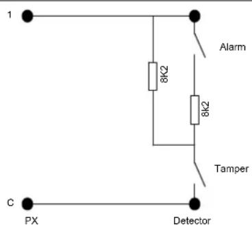
EOL Resistor Connections
Type 1 EOL Network (Guardall) Type 2 EOL Network The EOL resistors are fitted in
text_image
1 Alarm 8K2 8K2 Tamper C PX Detector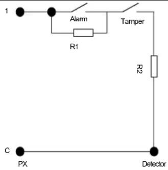
text_image
1 Alarm Tamper R1 R2 C PX Detectorthe detector as shown. This wiring arrangement applies to all EOL inputs in the system.
Note: The diagram shows the default values of 8k2//8k2. The EOL resistor value can be programmed (Refer to the system options for details.).
EOL Network with Fault The EOL
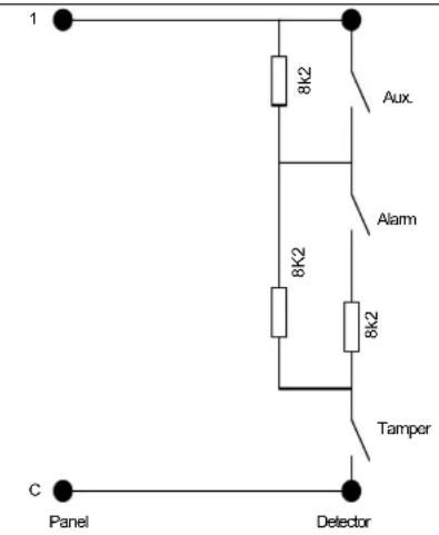
text_image
1 8k2 Aux. Alarm 8k2 8k2 Tamper C Panel Detectorresistors are fitted in the detector as shown. Note that most Guardall detectors have the necessary 3 EOL resistors fitted on board. For full information refer to the detector manual.
A fault EOL resistor may only be used if the system is programmed to use the standard Guardall resistor network.
The resistance for each possible state is shown in the table and can be displayed using the circuit check mode function.
| Circuit State Nominal Resistance | |
| Tamper | 0k |
| Clear | 4k1 |
| Alarm | 8k2 |
| Aux (Fault) 12k3 | |
| Aux+Alarm (Mask) | 16k4 |
| Tamper | >20k |
Diagnostics
Diagnostics
Accuracy
The accuracy of the diagnostic system is typically less than 1%, with a maximum error 2.5%. This accuracy can only be achieved by programming the correct value of the 5V-reference voltage (option 69 on the main menu).
Diagnostics
Supply Measurements
| Parameter Range Resolution | ||
| Panel voltage 0-20v 78mV | ||
| Panel battery voltage 0-20v 78mV | ||
| System current 0-2A 7.8mA | ||
| Battery Current 0-1.1A 4.4mA | ||
| Battery standby capacity See Note 1 hour | ||
| Concentrator current 0-250mA 1mA | ||
| Concentrator voltage 0-15V 58mV | ||
| Keypad voltage 0-15V 58mV | ||
| Circuit resistance (for 8k2 EOL) | 0-20K 70R |
Note: The displayed standby capacity will depend on the programmed battery size and the actual system current.
Diagnostics
XiB Comms LED
All XiB peripherals, except the keypad, have a green LED fitted, which is used to indicate the state of the XiB communications.
| State | Meaning |
| OFF | No power |
| ON | Communication error |
| Slow FLASH | Operating normally |
| Quick FLASH | Resetting, or frequency of polling in a dialler, serial module or IP module |
Diagnostics
Circuit Limits
| Option | Default | RX16i/QX32i/PX48i/PX80i/PX250i | Concentrator | Keypad | Access Module |
| Debounce time | 200ms | 2.2-500ms (inputs 1-3)14-500ms (inputs 4-8) | 2-500ms (inputs 1-4)10-500ms (inputs 5-8) | 200ms | 200ms |
| Pulse count | 0 (Off) | 0-255 | 0-255 | Not Applicable | Not Applicable |
| Pulse count period | 2 secs | 2-255 seconds | 2-255 seconds | Not Applicable | Not Applicable |
| Tamper resistor | 8k2 | Programmable | Programmable | Programmable | 8k2 |
| Alarm resistor | 8k2 | Programmable | Programmable | Programmable | 8k2 |
| Alarm/Tamper threshold | 30% | 30-100 | 30-100 | 20% | 20% |
All percentages are with reference to the nominal programmed EOL value. The alarm and tamper EOL resistors are programmable. Refer to system options in the engineer manual for details.
RX16i/QX32i Control Unit
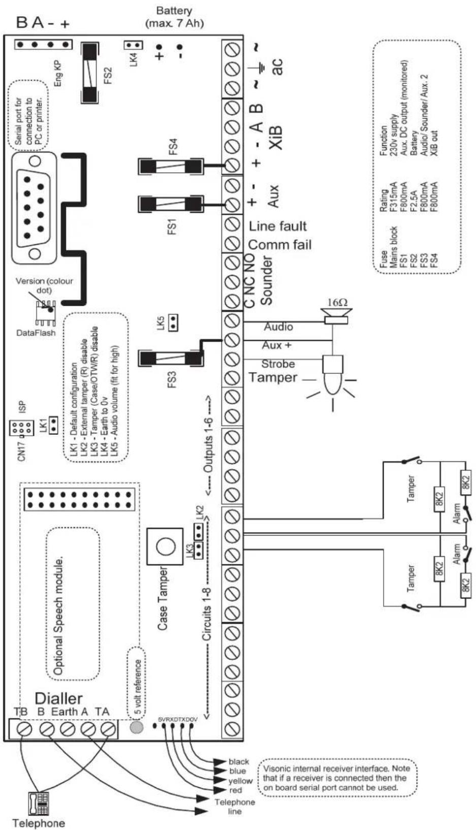
text_image
BA - + Battery (max. 7 Ah) Eng KP FS2 LK4 + - Version (colour dot) DataFlash ISP LN1 LN1 - Default configuration LN2 - External tamper (R) disable LN3 - Tamper (Case/OTWR) disable LN4 - Earth to 0v LN5 - Audio volume (fit for high) LN6 - Default configuration LN7 - External tamper (R) disable LN8 - Tamper (Case/OTWR) disable LN9 - Earth to 0v LN10 - Audio volume (fit for high) LN11 - Default configuration LN12 - External tamper (R) disable LN13 - Tamper (Case/OTWR) disable LN14 - Earth to 0v LN15 - Audio volume (fit for high) LN16 - Default configuration LN17 - External tamper (R) disable LN18 - Tamper (Case/OTWR) disable LN19 - Earth to 0v LN20 - Audio volume (fit for high) LN21 - Default configuration LN22 - External tamper (R) disable LN23 - Tamper (Case/OTWR) disable LN24 - Earth to 0v LN25 - Audio volume (fit for high) LN26 - Default configuration LN27 - External tamper (R) disable LN28 - Tamper (Case/OTWR) disable LN29 - Earth to 0v LN30 - Audio volume (fit for high) LN31 - Default configuration LN32 - External tamper (R) disable LN33 - Tamper (Case/OTWR) disable LN34 - Earth to 0v LN35 - Audio volume (fit for high) LN36 - Default configuration LN37 - External tamper (R) disable LN38 - Tamper (Case/OTWR) disable LN39 - Earth to 0v LN40 - Audio volume (fit for high) LN41 - Default configuration LN42 - External tamper (R) disable LN43 - Tamper (Case/OTWR) disable LN44 - Earth to 0v LN45 - Audio volume (fit for high) LN46 - Default configuration LN47 - External tamper (R) disable LN48 - Tamper (Case/OTWR) disable LN49 - Earth to 0v LN50 - Audio volume (fit for high) LN51 - Default configuration LN52 - External tamper (R) disable LN53 - Tamper (Case/OTWR) disable LN54 - Earth to 0v LN55 - Audio volume (fit for high) LN56 - Default configuration LN57 - External tamper (R) disable LN58 - Tamper (Case/OTWR) disable LN59 - Earth to 0v LN60 - Audio volume (fit for high) LN61 - Default configuration LN62 - External tamper (R) disable LN63 - Tamper (Case/OTWR) disable LN64 - Earth to 0v LN65 - Audio volume (fit for high) LN66 - Default configuration LN67 - External tamper (R) disable LN68 - Tamper (Case/OTWR) disable LN69 - Earth to 0v LN70 - Audio volume (fit for high) LN71 - Default configuration LN72 - External tamper (R) disable LN73 - Tamper (Case/OTWR) disable LN74 - Earth to 0v LN75 - Audio volume (fit for high) LN76 - Default configuration LN77 - External tamper (R) disable LN78 - Tamper (Case/OTWR) disable LN79 - Earth to 0v LN80 - Audio volume (fit for high) LN81 - Default configuration LN82 - External tamper (R) disable LN83 - Tamper (Case/OTWR) disable LN84 - Earth to 0v LN85 - Audio volume (fit for high) LN86 - Default configuration LN87 - External tamper (R) disable LN88 - Tamper (Case/OTWR) disable LN89 - Earth to 0v LN90 - Audio volume (fit for high) LN91 - Default configuration LN92 - External tamper (R) disable LN93 - Tamper (Case/OTWR) disable LN94 - Earth to 0v LN95 - Audio volume (fit for high) LN96 - Default configuration LKC1 LKC2 LKC3 LKC4 LKC5 LKC6 LKC7 LKC8 LKC9 LKC10 LKC11 LKC12 LKC13 LKC14 LKC15 LKC16 LKC17 LKC18 LKC19 LKC20 LKC21 LKC22 LKC23 LKC24 LKC25 LKC26 LKC27 LKC28 LKC29 LKC30 LKC31 LKC32 LKC33 LKC34 LKC35 LKC36 LKC37 LKC38 LKC39 LKC40 LKC41 LKC42 LKC43 LKC44 LKC45 LKC46 LKC47 LKC48 LKC49 LKC50 Line fault Comm fail Sounder CNC NO 16Ω Audio + - Aux + - AUX + - XIB AC Function Main block Rating F315mA Aux. DC output (monitored) F800mA F2.5A Battery F800mA Audio/Sounder/Aux. 2 FUS Main block FS1 FS2 FS3 FS4 Fuse Main block MS1 MS2 MS3 MS4 Ampl Ampl Alam Tamper Tape Black blue yellow red Telephone 5 vol reference SVRXDTXD0V Visonic internal receiver interface. Note that if a receiver is connected then the on board serial port cannot be used. Telephone linePX48i/PX80i/PX250i Control Unit
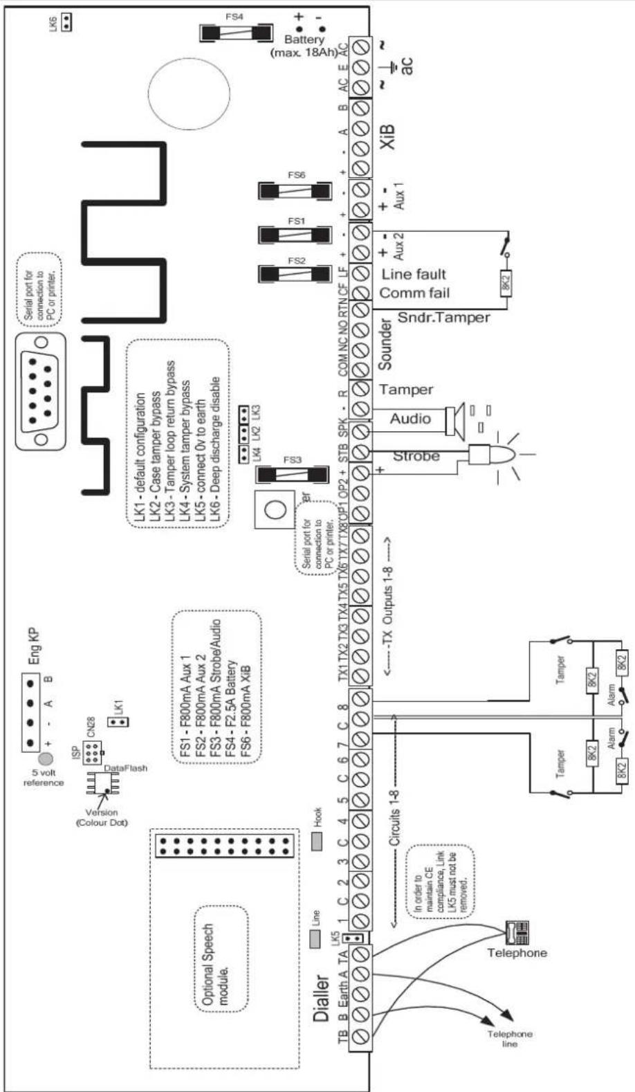
text_image
Eng KP 5 volt reference Version Colour Dog ISP CN28 LK1 Serial port for connection to PC or printer. LK6 Optional Speech module. FS1 - F800mA Aux 1 FS2 - F800mA Aux 2 FS3 - F800mA Strobe/Audio FS4 - F2.5A Battery FS6 - F800mA XiB LS1 - default configuration LS2 - Case tamper bypass LS3 - Tamper loop return bypass LS4 - System tamper bypass LS5 - connect 0v to earth LS6 - Deep discharge disable LS4 (max. 18Ah) FS4 Battery Line Line Hook Serial port for connection to PC or printer. FS3 TB B Earth A TA LK5 1 C 2 3 C 4 5 C 6 7 C 8 TX1 TX2 TX3 TX4 TX5 TX6 TX7 TX8 OP1 OP2 + STB SPK - R COM NC NO RTN CF LF + - + - + - A B AC E AC Dialler Circuits 1-8 In order to maintain CE compliance, Link LK5 must not be removed. Telephone line Telephone Tamper 8K2 Tamper 8K2 Alarm Alarm TA TX Outputs 1-8 → Solder Sndr.Tamper Audio Line fault Comm fail 8K2 + - + - Aux 1 XiB ~ ∼ acPX500/PX250HS Control Unit
PX500/PX250HS Control Unit
Installation
The PX 500 control panel is supplied with a spares bag containing the following items:
- Battery lead
- Cable clamp
- 2.5A fuse
• 800mA fuse x 8 (PX500/HS) - Screw No 6 x 19mm
• 2 Screws No 6 x 9.5mm - 2 ty-wraps
- 4 PCB stand-offs for fitting a XiB peripheral inside the case
- Various 2, 3, 4 and 5 way plug-on connectors
- 8k2 resistor x 2
- Thermistor cable assembly. (battery temperature compensation)
PX500/PX250HS Control Unit
Case Layout
Mark the fixing positions shown and secure the rear case to the wall using 3 suitable screws.
There are 2 x 20mm conduit knockout positions as indicated. The required cable entry point(s) should be knocked out from the inside prior to mounting the case.
There are 4 trunking knockouts. These can be knocked out from either side.
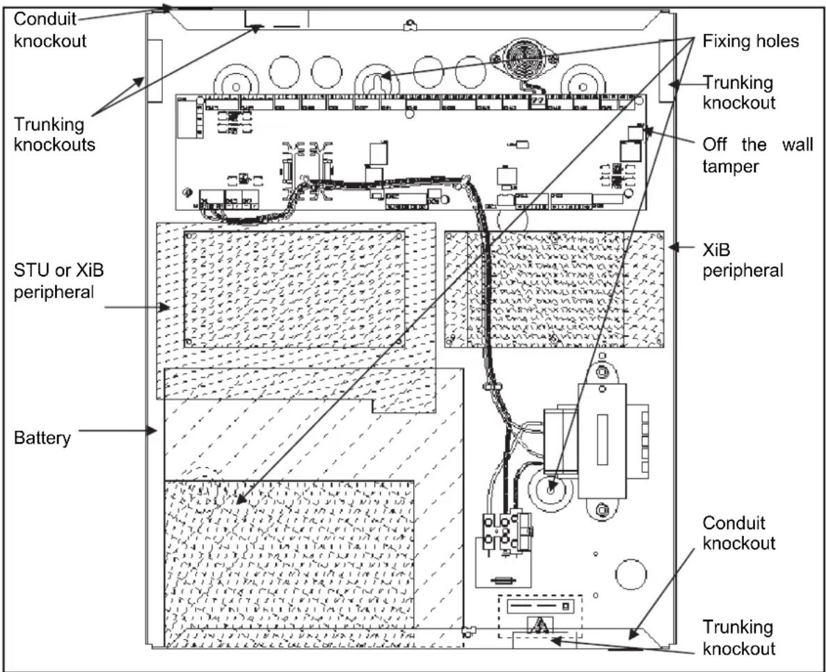
text_image
Conduit knockout Trunking knockouts STU or XiB peripheral Battery Fixing holes Trunking knockout Off the wall tamper XiB peripheral Conduit knockout Trunking knockoutPX500/PX250HS
PCB Connections (PX500/PX250HS)
All PCB connections are plug-on screw down terminal blocks. The function and position of each terminal is described in the following page.
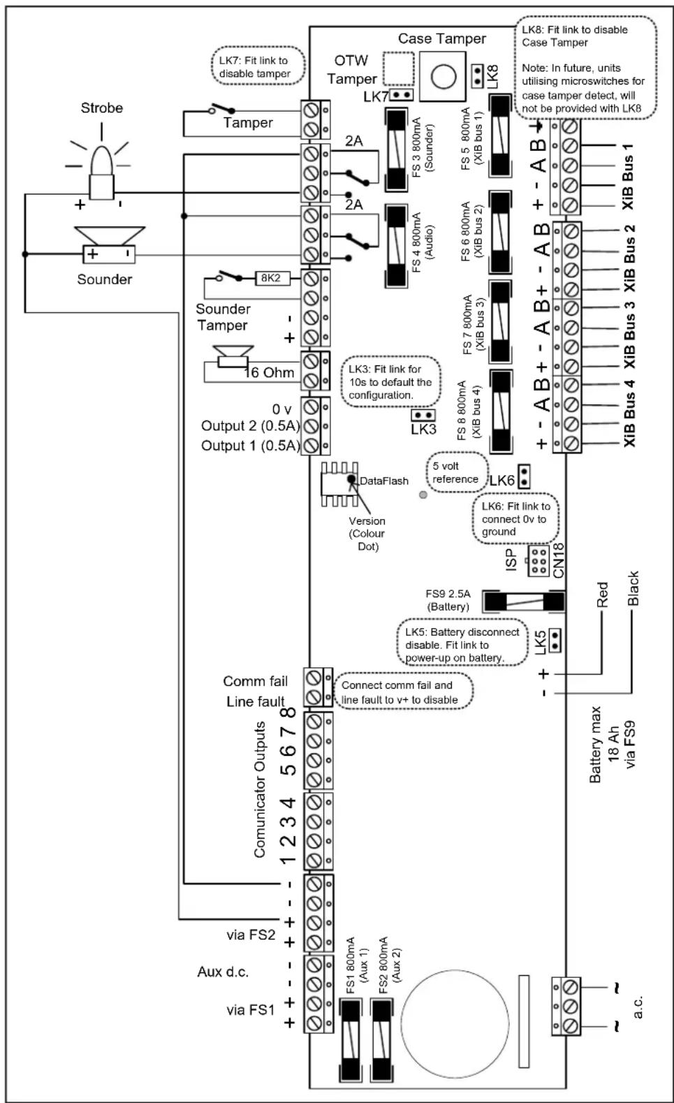
text_image
Strobe + - Sounder LK7: Fit link to disable tamper OTW Tamper LK7 Case Tamper LK8: Fit link to disable Case Tamper Note: In future, units utilising microswitches for case tamper detect, will not be provided with LK8 2A 2A FS 3 800mA (Sounder) FS 5 800mA (XIB bus 1) 2A FS 4 800mA (Audio) FS 6 800mA (XIB bus 2) 8K2 + - Sounder Tamper + - 16 Ohm LK3: Fit link for 10s to default the configuration. 0 v Output 2 (0.5A) Output 1 (0.5A) LK3 DataFlash Version (Colour Dot) 5 volt reference LK6 LK6: Fit link to connect 0v to ground ISP CN18 FS9 2.5A (Battery) LK5: Battery disconnect disable. Fit link to power-up on battery. + - + - comm fail Line fault 1234 5678 Connect comm fail and line fault to v+ to disable COMUNICATOR OUTPUTS via FS2 Aux d.c. via FS1 FS1 800mA (Aux 1) FS2 800mA (Aux 2) RK5 Red Black Battery max 18 Ah via FS9 a.c.In order to ensure CE compliance, a varistor shall be connected between + pin and the earth pin of XiB bus 1 connector. A second varistor is also required between the - pin and the earth pin of the same connector.
8 Input Concentrator
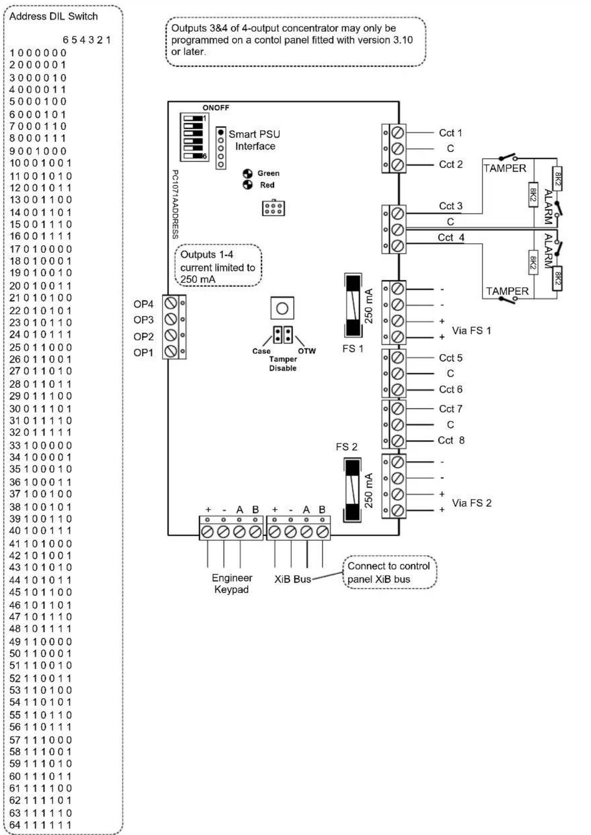
text_image
Address DIL Switch 6 5 4 3 2 1 1 0 0 0 0 0 0 2 0 0 0 0 0 1 3 0 0 0 0 1 0 4 0 0 0 0 1 1 5 0 0 0 1 0 0 6 0 0 0 1 0 1 7 0 0 0 1 1 0 8 0 0 0 1 1 1 9 0 0 1 0 0 0 10 0 0 1 0 0 1 11 0 0 1 0 1 0 12 0 0 1 0 1 1 13 0 0 1 1 0 0 14 0 0 1 1 0 1 15 0 0 1 1 1 0 16 0 0 1 1 1 1 17 0 1 0 0 0 0 18 0 1 0 0 0 1 19 0 1 0 0 1 0 20 0 1 0 0 1 1 21 0 1 0 1 0 0 22 0 1 0 1 0 1 23 0 1 0 1 1 0 24 0 1 0 1 1 1 25 0 1 1 0 0 0 26 0 1 1 0 0 1 27 0 1 1 0 1 0 28 0 1 1 0 1 1 29 0 1 1 1 0 0 30 0 1 1 1 0.1 31.0.1.1.1.1.1 32.0.1.1.1.1.1 33.1.0.0.0.0.0 34.1.0.0.0.0.1 35.1.0.0.0.1.0 36.1.0.0.0.1.1 37.1.0.0.1.0.0 38.1.0.0.1.0.1 39.1.0.0.1.1.0 40.1.0.1.1.1.1 41.1.0.1.2.2.2. 42.1.2.2.2.2. 43.2.2.2.2.2. 44.2.2.2.2.2. 45.2.2.2.2.2. 46.2.2.2.2.2. 47.2.2.2.2.2. 48.2.2.2.2.2. 49.2.2.2.2.2. 50.2.2.2.2.2. 51.2.2.2.2.2. 52.2.2.2.2.2. 53.2.2.2.2.2. 54.2.2.2.2.2. 55.2.2.2.2.2. 56.2.2.2.2.2. 57.2.2.2.2.2. 58.2.2.2.2.2. 59.2.2.2.2.2. 60.2.2.2.2.2. 61.2.2.2.2.2. 62.2.2.2.2. 63.2.2.2.2. 64.2.2.2.4 Input Concentrator
| Address DIL Switch | Address DIL Switch |
| 7 6 5 4 3 2 1 | 7 6 5 4 3 2 1 |
| 1 0 0 0 0 0 0 0 | 65 1 0 0 0 0 0 0 |
| 2 0 0 0 0 0 0 1 | 66 1 0 0 0 0 0 1 |
| 3 0 0 0 0 0 1 0 | 67 1 0 0 0 0 1 0 |
| 4 0 0 0 0 0 1 1 | 68 1 0 0 0 0 1 1 |
| 5 0 0 0 0 1 0 0 | 69 1 0 0 0 1 0 0 |
| 6 0 0 0 0 1 0 1 | 70 1 0 0 0 1 0 1 |
| 7 0 0 0 0 1 1 0 | 71 1 0 0 0 1 1 0 |
| 8 0 0 0 0 1 1 1 | 72 1 0 0 0 1 1 1 |
| 9 0 0 0 1 0 0 0 | 73 1 0 0 1 0 0 0 |
| 10 0 0 0 1 0 0 1 | 74 1 0 0 1 0 0 1 |
| 11 0 0 0 1 0 1 0 | 75 1 0 0 1 0 1 0 |
| 12 0 0 0 1 0 1 1 | 76 1 0 0 1 0 1 1 |
| 13 0 0 0 1 1 0 0 | 77 1 0 0 1 1 0 0 |
| 14 0 0 0 1 1 0 1 | 78 1 0 0 1 1 0 1 |
| 15 0 0 0 1 1 1 0 | 79 1 0 0 1 1 1 0 |
| 16 0 0 0 1 1 1 1 | 80 1 0 0 1 1 1 1 |
| 17 0 0 1 0 0 0 0 | 81 1 0 1 0 0 0 0 |
| 18 0 0 1 0 0 0 1 | 82 1 0 1 0 0 0 1 |
| 19 0 0 1 0 0 1 0 | 83 1 0 1 0 0 1 0 |
| 20 0 0 1 0 0 1 1 | 84 1 0 1 0 0 1 1 |
| 21 0 0 1 0 1 0 0 | 85 1 0 1 0 1 0 0 |
| 22 0 0 1 0 1 0 1 | 86 1 0 1 0 1 0 1 |
| 23 0 0 1 0 1 1 0 | 87 1 0 1 0 1 1 0 |
| 24 0 0 1 0 1 1 1 | 88 1 0 1 0 1 1 1 |
| 25 0 0 1 1 0 0 0 | 89 1 0 1 1 0 0 0 |
| 26 0 0 1 1 0 0 1 | 90 1 0 1 1 0 0 1 |
| 27 0 0 1 1 0 1 0 | 91 1 0 1 1 0 1 0 |
| 28 0 0 1 1 0 1 1 | 92 1 0 1 1 0 1 1 |
| 29 0 0 1 1 1 0 0 | 93 1 0 1 1 1 0 0 |
| 30 0 0 1 1 1 0 1 | 94 1 0 1 1 1 0 1 |
| 31 0 0 1 1 1 1 0 | 95 1 0 1 1 1 1 0 |
| 32 0 0 1 1 1 1 1 | 96 1 0 1 1 1 1 1 |
| 33 0 1 0 0 0 0 0 | 97 1 1 0 0 0 0 0 |
| 34 0 1 0 0 0 0 1 | 98 1 1 0 0 0 0 1 |
| 35 0 1 0 0 0 1 0 | 99 1 1 0 0 0 1 0 |
| 36 0 1 0 0 0 1 1 | 100 1 1 0 0 0 1 1 |
| 37 0 1 0 0 1 0 0 | 101 1 1 0 0 1 0 0 |
| 38 0 1 0 0 1 0 1 | 102 1 1 0 0 1 0 1 |
| 39 0 1 0 0 1 1 0 | 103 1 1 0 0 1 1 0 |
| 40 0 1 0 0 1 1 1 | 104 1 1 0 0 1 1 1 |
| 41 0 1 0 1 0 0 0 | 105 1 1 0 1 0 0 0 |
| 42 0 1 0 1 0 0 1 | 106 1 1 0 1 0 0 1 |
| 43 0 1 0 1 0 1 0 | 107 1 1 0 1 0 1 0 |
| 44 0 1 0 1 0 1 1 | 108 1 1 0 1 0 1 1 |
| 45 0 1 0 1 1 0 0 | 109 1 1 0 1 1 0 0 |
| 46 0 1 0 1 1 0 1 | 110 1 1 0 1 1 0 1 |
| 47 0 1 0 1 1 1 0 | 111 1 1 0 1 1 1 0 |
| 48 0 1 0 1 1 1 1 | 112 1 1 0 1 1 1 1 |
| 49 0 1 1 0 0 0 0 | 113 1 1 1 0 0 0 0 |
| 50 0 1 1 0 0 0 1 | 114 1 1 1 0 0 0 1 |
| 51 0 1 1 0 0 1 0 | 115 1 1 1 0 0 1 0 |
| 52 0 1 1 0 0 1 1 | 116 1 1 1 0 0 1 1 |
| 53 0 1 1 0 1 0 0 | 117 1 1 1 0 1 0 0 |
| 54 0 1 1 0 1 0 1 | 118 1 1 1 0 1 0 1 |
| 55 0 1 1 0 1 1 0 | 119 1 1 1 0 1 1 0 |
| 56 0 1 1 0 1 1 1 | 120 1 1 1 0 1 1 1 |
| 57 0 1 1 1 0 0 0 | 121 1 1 1 1 0 0 0 |
| 58 0 1 1 1 0 0 1 | 122 1 1 1 1 0 0 1 |
| 59 0 1 1 1 0 1 0 | 123 1 1 1 1 0 1 0 |
| 60 0 1 1 1 0 1 1 | 124 1 1 1 1 0 1 1 |
| 61 0 1 1 1 1 0 0 | 125 1 1 1 1 1 0 0 |
| 62 0 1 1 1 1 0 1 | 126 1 1 1 1 1 0 1 |
| 63 0 1 1 1 1 1 0 | 127 1 1 1 1 1 1 0 |
| 64 0 1 1 1 1 1 1 | 128 1 1 1 1 1 1 1 |
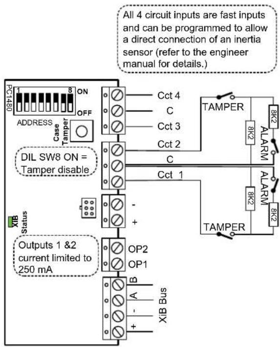
text_image
All 4 circuit inputs are fast inputs and can be programmed to allow a direct connection of an inertia sensor (refer to the engineer manual for details.) PC1480 ON OFF ADDRESS case TAMPER 8K2 ALARM Cct 4 C Cct 3 Cct 2 C DIL SW8 ON = Tamper disable Cct 1 - + OP2 OP1 B A - + + Status Outputs 1 &2 current limited to 250 mA XIB Bus3A Smart Concentrator
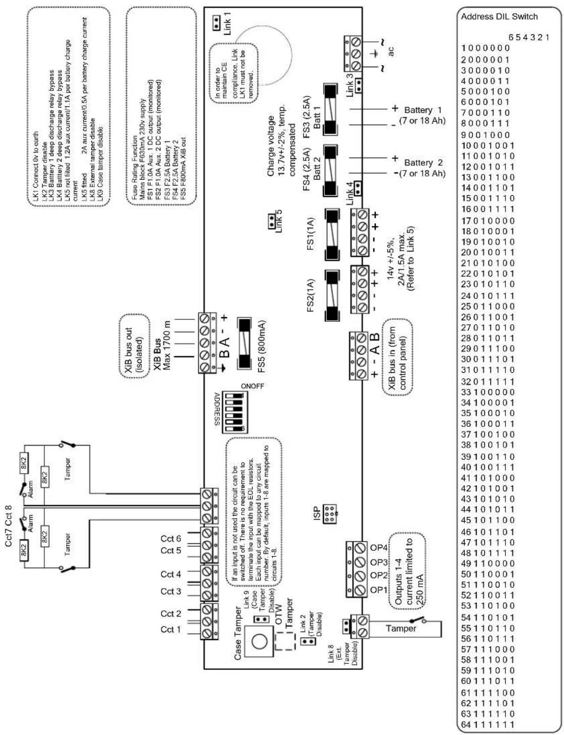
The 3A Smart concentrator can be used with a single battery or 2 batteries. If 2 batteries are used they should be of the same type and capacity. If a single battery is used it should be connected to the Batt 1 terminals. The case can accommodate 7Ah or 18Ah batteries. Deep discharge protection is provided for each battery.
text_image
Cct7 Cct 8 8K2 Alarm 8K2 Tampper 8K2 Tampper Cct 1 Cct 2 Cct 3 Cct 4 Cct 5 Cct 6 Case Tamper Link 9 (Case Tamper Disable) OTW Tamper Link 2 (Tamper Disable) Link 8 (Ext. Tamper Disable) Tampper If an input is not used the circuit can be switched off. There is no requirement to terminate the input with the EOL resistors. Each input can be mapped to any circuit number. By default, inputs 1-8 are mapped to circuits 1-8. Output 1-4 current limited to 250 mA ISP XIB bus out (isolated) XIB Bus Max 1700 m ONOFF CSRESSE BA- FS5 (800mA) Link 5 Charge voltage 13.7v+/-2%, temp. compensated FS2(1A) FS1(1A) FS4 (2.5A) FS3 (2.5A) Batt 2 Batt 1 + - A B XIB bus in (from control panel) 14v +/-5%, 2A/1.5A max. (Refer to Link 5) - (-7 or 18 Ah) - + Battery 2 - + Battery 1 - (-7 or 18 Ah) ac Link 3 Link 1 LK1 Connect 0v to earth LK2 Tamper disable LK3 Battery 1 deep discharge relay bypass LK4 Battery 2 deep discharge relay bypass LK5 not filled 1.2A aux current/1.1A per battery charge current LK5 fitted 2A aux current/0.5A per battery charge current LK8 External tamper disable LK9 Case tamper disable Fuse Rating Function Mains block F630mA 230v supply FS1 F1.0A Aux. 1 DC output (monitored) FS2 F1.0A Aux. 2 DC output (monitored) FS3 F2.5A Battery 1 FS4 F2.5A Battery 2 FS5 F800mA Xib out in order to maintain CE compliance, Link LK1 must not be removed.3A Smart Concentrator
XiB Bus
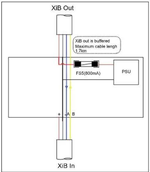
The 3A Smart Concentrator has 2 XiB connectors, XiB in and XiB out. The XiB in connector must be used to connect the XiB bus from the panel. All 4 wires may be connected but the XiB in + terminal is not connected to the XiB out + terminal. The XiB out connector is used to connect all XiB peripherals that are to be powered from the 3A Smart Concentrator. The XiB out bus is electrically isolated from the XiB in bus and peripherals can be connected on the XiB out bus up to 1.7km from the 3A Smart concentrator (at 9k6 baud).
text_image
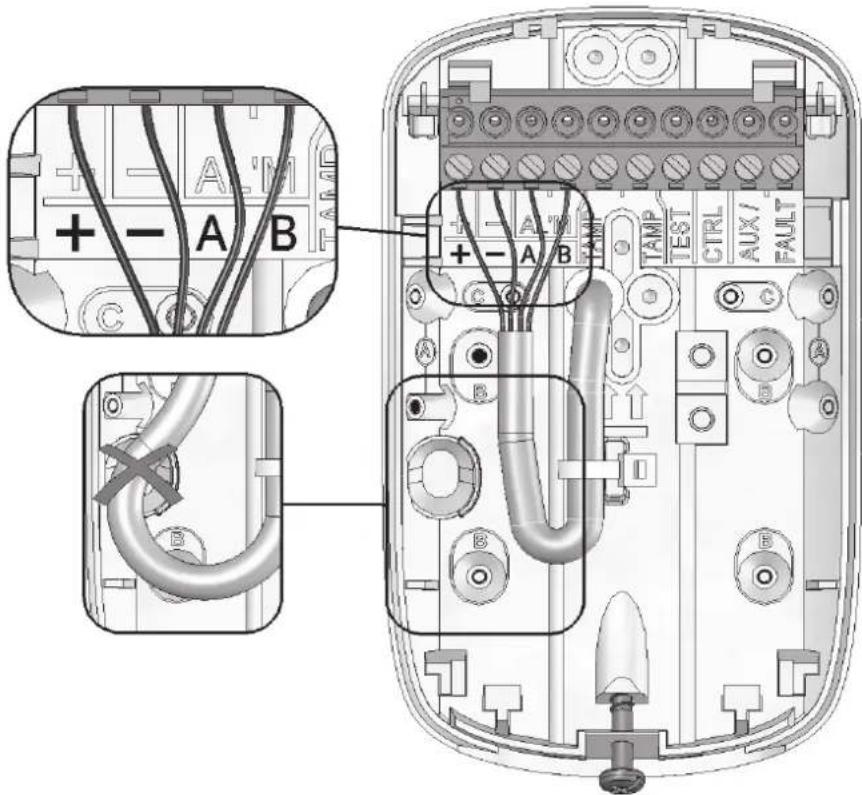
XiB Out XiB out is buffered Maximum cable length 1.7km FS5(800mA) PSU + A B XiB InXiB Detectors
text_image
Technical diagram of an electronic device showing labeled components including connectors, cables, and terminal blocks with annotations A, B, C, D.Refer to the relevant XiB Detector installation manual for the connection details
PQ15 XiB Manual Part No: 321094
PQ15-AM XiB Manual Part No: 321097
DT15+ XiB Manual Part No: 321106
DT15-AM XiB Manual Part No: 321113
Output Module
text_image
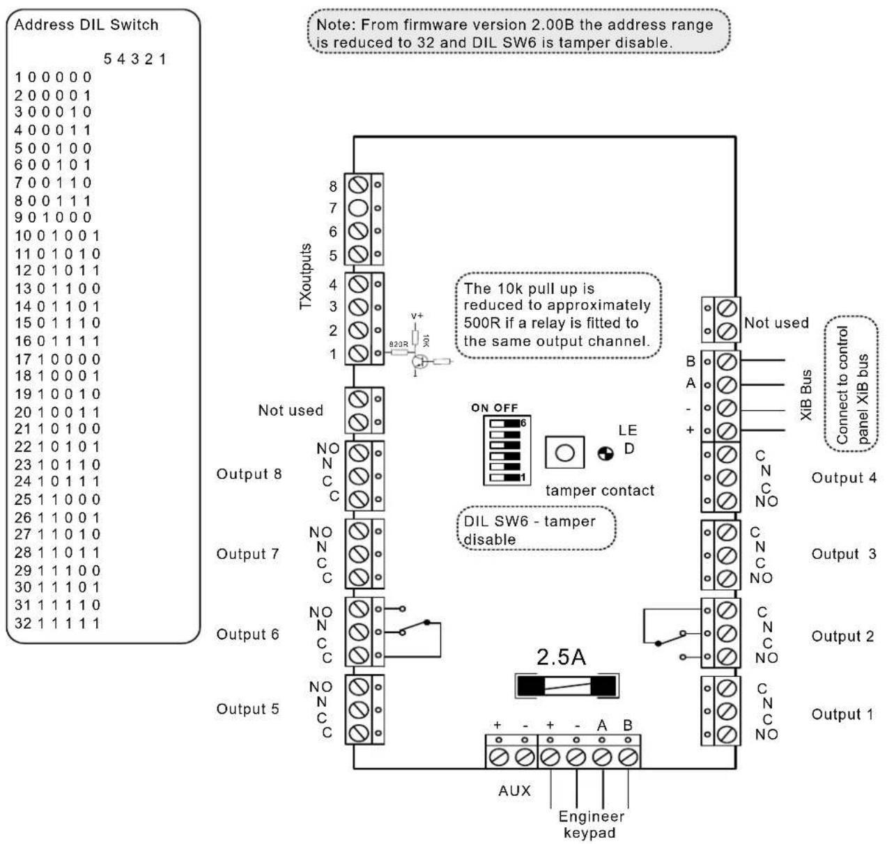
Address DIL Switch 5 4 3 2 1 1 0 0 0 0 0 2 0 0 0 0 1 3 0 0 0 1 0 4 0 0 0 1 1 5 0 0 1 0 0 6 0 0 1 0 1 7 0 0 1 1 0 8 0 0 1 1 1 9 0 1 0 0 0 10 0 1 0 0 1 11 0 1 0 1 0 12 0 1 0 1 1 13 0 1 1 0 0 14 0 1 1 0 1 15 0 1 1 1 0 16 0 1 1 1 1 17 1 0 0 0 0 18 1 0 0 0 1 19 1 0 0 1 0 20 1 0 0 1 1 21 1 0 1 0 0 22 1 0 1 0 1 23 1 0 1 1 0 24 1 0 1 1 1 25 1 1 0 0 0 26 1 1 0 0 1 27 1 1 0 1 0 28 1 1 0 1 1 29 1 1 1 0 0 30 1 1 1 0 1 31 1 1 1 1 0 32 1 1 1 1 TXoutputs 8 7 6 5 4 3 2 1 8/23R V+ B23R The 10k pull up is reduced to approximately 500R if a relay is fitted to the same output channel. Not used ON OFF 6 LE D tamper contact B A - + C N C NO XIB Bus Connect to control panel XIB bus Output 4 Output 3 Output 2 Output 1 DIL SW6 - tamper disable NON NC C Output 7 NON NC C Output 6 NON NC C Output 5 NON NC C 2.5A + - + - A B Aux Engineer keypad AUXSerial Module
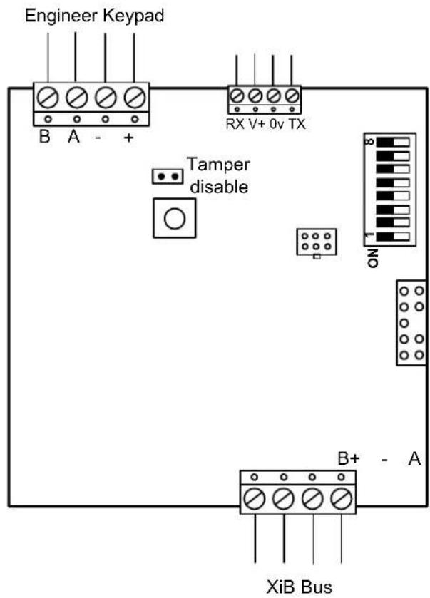
text_image
Engineer Keypad B A - + RX V+ 0v TX Tamper disable NO B+ - A XiB BusAddress DIL Switch 8 7 6 5 4 3 2 1 1 XXXX0000 2 XXXX0001
A serial module can be added at any time to a powered system but must be added to the system size before it will operate.
The function switches only apply to versions up to v3.20.
Function DIL Switch 8 7 6 5 Printer/PC 0 0 0 0 Printer 0 0 0 1 PC 0 0 1 0
The printer format is fixed at 1200 baud, no parity, 8 data bits and 1 stop bit. PC baud rate is 9600.
Data Comms Module
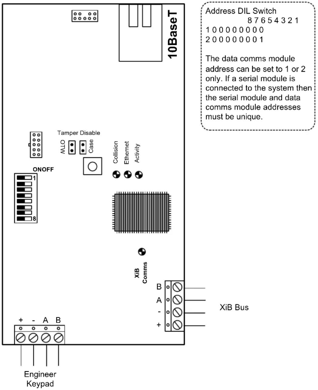
text_image
10BaseT Address DIL Switch 8 7 6 5 4 3 2 1 1 0 0 0 0 0 0 0 0 2 0 0 0 0 0 0 0 1 The data comms module address can be set to 1 or 2 only. If a serial module is connected to the system then the serial module and data comms module addresses must be unique. Tamper Disable Case Collision Ethernet Activity ON/OFF 1 8 XiB Comms + - A B Engineer Keypad B A - + XiB BusKeypad
text_image
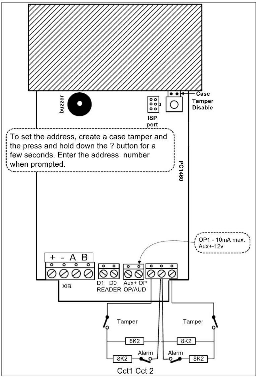
buzzer ISP port Case Tamper Disable PC1460 To set the address, create a case tamper and the press and hold down the ? button for a few seconds. Enter the address number when prompted. + - A B XiB D1 D0 Aux+ OP READER OP/AUD OP1 - 10mA max. Aux+-12v Tamper 8K2 8K2 8K2 Alarm 8K2 Cct1 Cct 2Mini Keypad
The mini LCD proximity keypad is supported from v4.20.
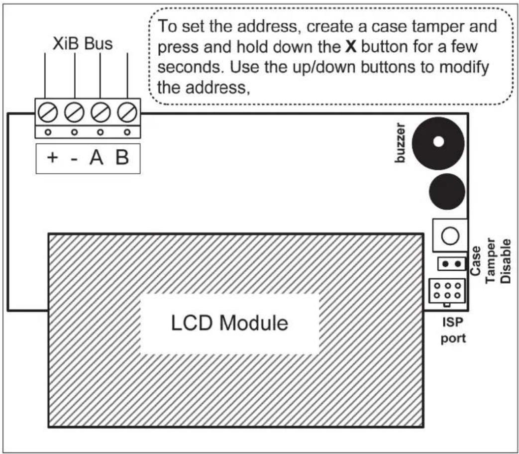
flowchart
graph TD
    A["+ - A B"] --> B["LCD Module"]
    B --> C["buzzer"]
    C --> D["Case Tamper Disable"]
    D --> E["ISP port"]
    F["XiB Bus"] --> B
    G["To set the address, create a case tamper and press and hold down the X button for a few seconds. Use the up/down buttons to modify the address,"]
Access Module
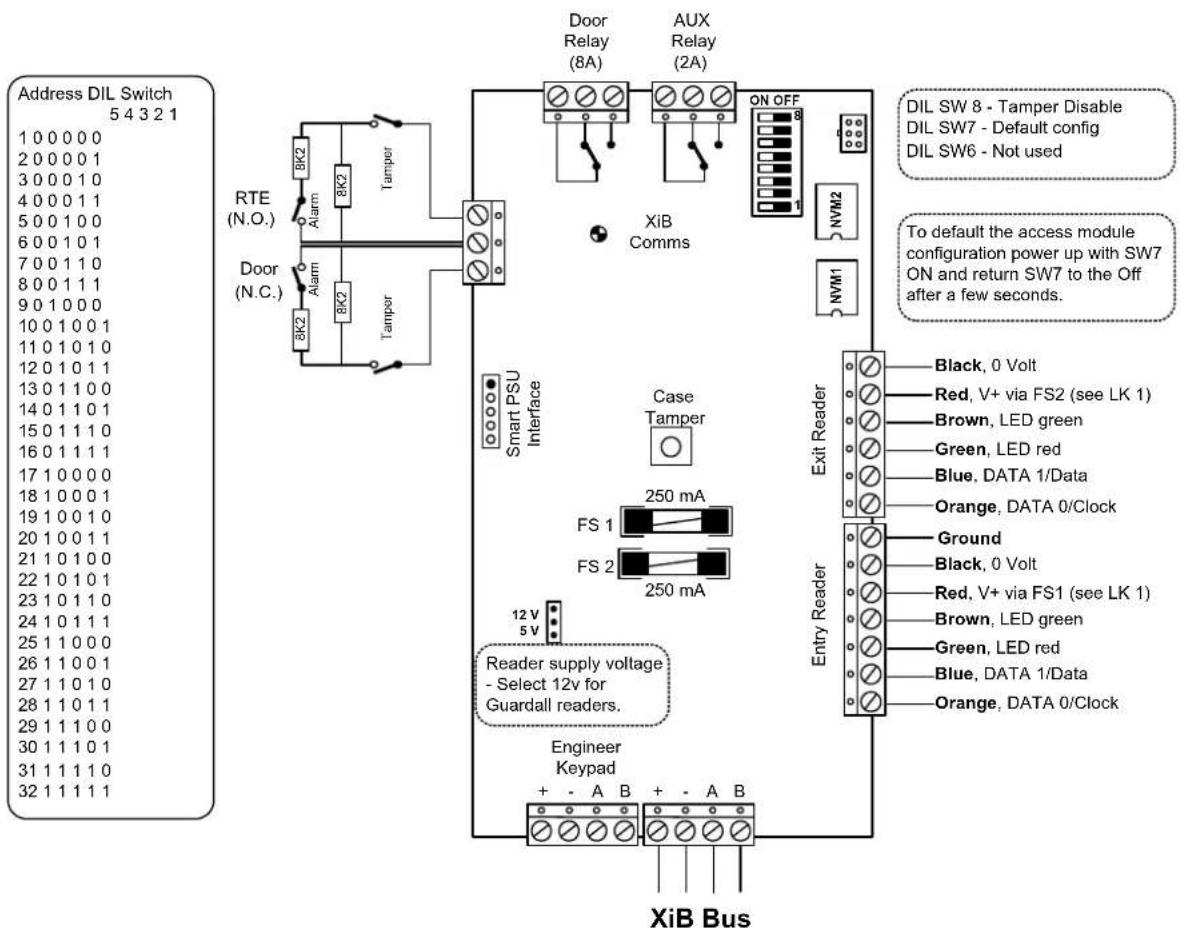
text_image
Address DIL Switch 5 4 3 2 1 1 0 0 0 0 0 2 0 0 0 0 1 3 0 0 0 1 0 4 0 0 0 1 1 5 0 0 1 0 0 6 0 0 1 0 1 7 0 0 1 1 0 8 0 0 1 1 1 9 0 1 0 0 0 10 0 1 0 0 1 11 0 1 0 1 0 12 0 1 0 1 1 13 0 1 1 0 0 14 0 1 1 0 1 15 0 1 1 1 0 16 0 1 1 1 1 17 1 0 0 0 0 18 1 0 0 0 1 19 1 0 0 1 0 20 1 0 0 1 1 21 1 0 1 0 0 22 1 0 1 0 1 23 1 0 1 1 0 24 1 0 1 1 1 25 1 1 0 0 0 26 1 1 0 0 1 27 1 1 0 1 0 28 1 1 0 1 1 29 1 1 1 0 0 30 1 1 1 0 1 31 1 1 1 1 0 32 1 1 1 1 1 RTE (N.O.) Alarm 8K2 8K2 Tamper Door (N.C.) Alarm 8K2 Tamper Smart PSU Interface Case Tamper FS 1 FS 2 250 mA 250 mA Reader supply voltage - Select 12v for Guardall readers. Engineer Keypad + - A B + - A B XiB Bus Door Relay (8A) AUX Relay (2A) ON OFF 8 NVM2 NVM1 Exit Reader Black, O Volt Red, V+ via FS2 (see LK 1) Brown, LED green Green, LED red Blue, DATA I/Data Orange, DATA O/Clock Ground Black, O Volt Red, V+ via FS1 (see LK 1) Brown, LED green Green, LED red Blue, DATA I/Data Orange, DATA O/ClockAccess Module
Smart Access Module
The smart access module includes a standard access module PCB and a power supply PCB. Only the power supply PCB is shown in the diagram.
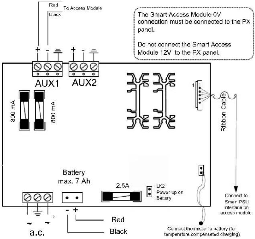
text_image
Red To Access Module Black AUX1 800 mA 800 mA AUX2 Battery max. 7 Ah 2.5A LK2 Power-up on Battery a.c. Red Black The Smart Access Module 0V connection must be connected to the PX panel. Do not connect the Smart Access Module 12V to the PX panel. 1 Ribbon Cable Connect to Smart PSU interface on access module Connect thermistor to battery (for temperature compensated charging)Proximity Reader
Proximity Reader
Access Module Connections
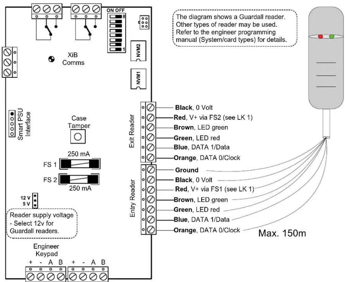
text_image
The diagram shows a Guardall reader. Other types of reader may be used. Refer to the engineer programming manual (System/card types) for details. XiB Comms NVM2 NVM1 Smart PSU Interface Case Tamper 250 mA FS 1 FS 2 250 mA 12 V 5 V Reader supply voltage - Select 12v for Guardall readers. Engineer Keypad + - A B + - A B Exit Reader Black, 0 Volt Red, V+ via FS2 (see LK 1) Brown, LED green Green, LED red Blue, DATA 1/Data Orange, DATA 0/Clock Entry Reader Ground Black, 0 Volt Red, V+ via FS1 (see LK 1) Brown, LED green Green, LED red Blue, DATA 1/Data Orange, DATA 0/Clock Max. 150mProximity Reader
LEDs
| Function Red LED | Green LED | |
| Door LOCKED ON OFF | ||
| Door UNLOCKED ON ON | ||
| INVALID card, Access DENIED or Access ACCEPTED but door not opened. | Flash for approximately 2 seconds | OFF |
| Access ACCEPTED, Area not in alarm | ON ON (when door open and locked, flash on for 1 second) | |
| Access ACCEPTED, Area was in alarm | Flash for approximately 2 seconds | ON |
| Door FORCED Alarm Flash ON | ||
| Door TAMPER Alarm Flash ON | ||
| Door area set OFF blink for 10 secs, then goes to Door Locked | secs, then goes to Door Locked | |
| Door OPEN Alarm Start / Finish | Flash (4 sec's) ON (4 sec's) | |
| Door area setting Slow flash on both LEDs | ||
| Module logging data or undergoing configuration | Fast flash OFF | |
| Lock out (continuous) Blink on both LEDs | ||
Proximity Reader
Keypad Connections
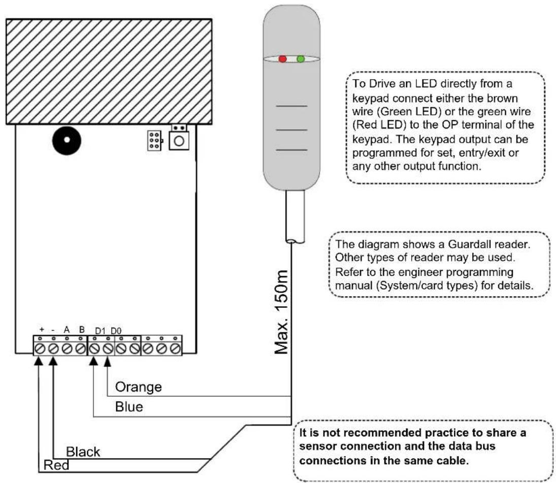
text_image
To Drive an LED directly from a keypad connect either the brown wire (Green LED) or the green wire (Red LED) to the OP terminal of the keypad. The keypad output can be programmed for set, entry/exit or any other output function. The diagram shows a Guardall reader. Other types of reader may be used. Refer to the engineer programming manual (System/card types) for details. It is not recommended practice to share a sensor connection and the data bus connections in the same cable. Max. 150m Orange Blue Black RedRadio Module
The radio module is fitted with 2 PCBs; a RF module and a serial interface for connection to the control panel XiB bus. The serial interface PCB is multi-function and for operation as a radio interface DIL switches 6 and 8 must be on and DIL switch 7 off. DIL switches 1-5 are used to select the radio module address. The diagram shows the Inovonics receiver module (W76067). The Visonic radio module (W76110) internal layout is similar. Refer to the serial module section for the connection details.
The radio module type must be programmed. Refer to the radio options in the engineer manual for more information.
| Address DIL Switch5 4 3 2 1 |
| 1 0 0 0 0 0 |
| 2 0 0 0 0 1 |
| 3 0 0 0 1 0 |
| 4 0 0 0 1 1 |
| 5 0 0 1 0 0 |
| 6 0 0 1 0 1 |
| 7 0 0 1 1 0 |
| 8 0 0 1 1 1 |
| 9 0 1 0 0 0 |
| 10 0 1 0 0 1 |
| 11 0 1 0 1 0 |
| 12 0 1 0 1 1 |
| 13 0 1 1 0 0 |
| 14 0 1 1 0 1 |
| 15 0 1 1 1 0 |
| 16 0 1 1 1 1 |
| 17 1 0 0 0 0 |
| 18 1 0 0 0 1 |
| 19 1 0 0 1 0 |
| 20 1 0 0 1 1 |
| 21 1 0 1 0 0 |
| 22 1 0 1 0 1 |
| 23 1 0 1 1 0 |
| 24 1 0 1 1 1 |
| 25 1 1 0 0 0 |
| 26 1 1 0 0 1 |
| 27 1 1 0 1 0 |
| 28 1 1 0 1 1 |
| 29 1 1 1 0 0 |
| 30 1 1 1 0 1 |
| 31 1 1 1 1 0 |
| 32 1 1 1 1 1 |
natural_image
Top-down schematic of an electronic device casing showing internal components and wiring (no text or labels)DIL switches 6-8 are factory set to the radio module function
Function DIL Switch 876 Radio 101
Radio Repeater
A radio repeater(s) may be added to the system. Each radio repeater should be added as a transmitter (refer to the engineer manual for details).
Battery Disposal
Disposal of batteries should be according to the local laws and regulations of your region. Contact your local waste management office for information on battery recycling or disposal.
If you are not able to identify the applicable rules in your area, please check the instructions which will be available from the battery manufacturer.
PSTN/GSM/Dual Comms module
Statutory Requirements
Hereby Guardall, declares that the Dual Comms module and PSTN module is in compliance with the essential requirements and other relevant provisions of Directive 1999/5/EC.
If you have any doubts concerning the suitability, connection or uses of this apparatus then consult a suitably qualified person before continuing.
SUITABILITY FOR USE
The apparatus has been designed to work on all European analogue networks. It provides the following facilities:
- Automatic Call Initiation.
- Series connection.
- Dial tone Detection
- Automatic dialling using DTMF tones.
- Automatic Call Answering.
- Stored number dialling.
-
Timed Break Register Recall.
-
Alarm transmission and transmission/reception of configuration data.
It is not suitable for connection to PABX systems or for use as an extension to a payphone.
The Dual comm module and the GSM module are fitted with a GSM engine which has been declared compliant with the essential requirements of Directive 1995/05/EC by the manufacturer Dia telecom Spa (Telit). The conformity assessment procedure referred to in Article 10 and detailed in Annex IV of Directive 1999/05/EC was carried out by a Notified Body, namely BABT, Walton-on-Thames, UK (Notified body number 0168).
Introduction
The Dual Comm module, GSM module and the PSTN module may be used with any Guardall control panel.
| Feature Implementation | |
| Transmission Voice and Frequency Band Dual Band | Data and EGSM900 and EGSM1800 |
| Transmit Power Class 4 | (2W) for EGSM 900MHzClass 1 (1W) for EGSM 1800MHz |
| Data | 9.6Kbps |
| Supported SIM card 3V | cards |
There are a number of important points to consider when using one of the new module types with an existing panel:
- All previous communicators were designed for use within the panel case and consequently they were designed with no tamper switch. The GSM/Dual comm module is intended for use outside the panel case, and so needs a case tamper. The GSM/Dual comm module case tamper is recognised from panel v4. If the GSM/Dual comm module used with earlier panel versions it is recommended that line fault monitoring is enabled to act as a substitute for the tamper sensing.
- The Dual comm module functions are programmed using the DIL switches. Future versions of the firmware will include additional menu options for GSM programmable functions.
The latest firmware release is V4.52c. This is necessary to enable older panel versions to recognise the module and allow access to the appropriate programming menus.
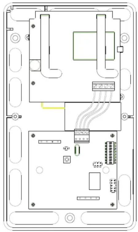
Installation
Special care is required when installing the GSM module or Dual Comm module;
- Avoid placement on metal surfaces to ensure good radio performance.
- To minimise GSM transmission interference, route all cables away from the GSM antenna.
- If the system includes Audio Modules ensure that there is at least 3m between the Audio Module(s) and the GSM/Dual Comm module.
- The maximum recommended XiB bus cable length between the power supply and the GSM/Dual Comm module is approximately 80m. This distance may be doubled if two cable cores are used for the power connections. This restriction is based on the peak current requirement of 180mA under poor signal conditions.
- Insert a valid SIM card into the slot provided in the GSM engine. SIM code password protection must be disabled.
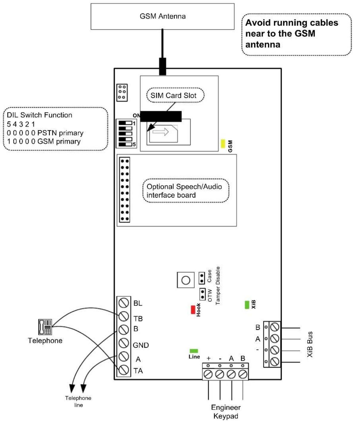
flowchart
graph TD
    A["GSM Antenna"] --> B["SIM Card Slot"]
    B --> C["Optional Speech/Audio Interface Board"]
    C --> D["Telephone"]
    D --> E["Telephone line"]
    F["Avoid running cables near to the GSM antenna"] --> B
    G["DIL Switch Function 5 4 3 2 1 0 0 0 0 0 PSTN primary 1 0 0 0 0 GSM primary"] --> B
    H["XiB Bus"] --> I["Engineer Keypad"]
    J["Line + - A B"] --> K["Line"]
    L["Telephone"] --> M["BL TB B GND A TA"]
    N["Hook OTW Case Tamper Disable"] --> O["Case"]
    P["GSM"] --> Q["ON"]
    R["Engineer Keypad"] --> S["Line"]
When power is applied to the system the GSM module will power up in 3 stages:
- The XiB communications will start before the end of system settling time (as indicated on the keypad). During this phase the XIB-comms LED will flash rapidly (awaiting secondary PSU startup)
- The GSM engine will start up after about 20 seconds. During this phase the XIB-comms LED will flash approximately once per second.
- Once powered up, the GSM engine will be configured automatically and will attempt to acquire a service connection. This phase may take several minutes and no GSM calls should be attempted during this phase.
LEDs
| Function Colour State Meaning | ||||
| XiB Comms Green OFF No power | ||||
| Slow FLASH | Operating normally | ON | Communication | error |
| ally | ||||
| Quick | FLASH | Active | ||
| Hook | Red | ON | Line | seized |
| Line monitor Green ON Valid E | Exchange voltage | level present | ||
| GSM Status | Yellow | Quick flash | Network search | |
| Slow flash | Registered | |||
| ON | Active call | |||
Reporting Formats
The available reporting formats for each route is shown in the table.
| Formats | Route | ||
| PSTN | GSM (audio) | GSM (data) | |
| Contact ID | √ | √ | ✗ |
| ADEMCO Fast/Superfast Format | √ | √ | ✗ |
| SIA Level 3 | √ | √ | ✗ |
| CESA (French panel variants only) | √ | √ | ✗ |
| Speech (if optional module fitted, v3.21 or later) | √ | √ | ✗ |
| Audio (if optional module fitted) | √ | √ | ✗ |
| PS/2 (GSR) - 1200 baud | √ | ✗ | ✗ |
| PS/2 (GSR) - 9600 baud | ✗ | ✗ | √ |
| SMS (v4.00 or later) | ✗ | √ | √ |
DIL Switches
To enable the Dual Comm module to be used with existing panels, the primary and secondary communicator routes are selected by DIL switch 5. DIL switches 1-4 are reserved for future use.
| DIL Switch5 4 3 2 1 | Function |
| 0 0 0 0 0 | PSTN is primary route |
| 1 0 0 0 0 | GSM is primary route |
The primary route is the normal route for all calls.
If the primary route is PSTN then;
• All calls in all formats will be routed over the PSTN network
- If there is a PSTN line fault then all calls will be routed over the GSM network (refer to the reporting formats table for details)
Note: If the call format is PS/2 and there is a PSTN line fault then the call will be made on the same number of GSM. This call will fail as the Windsor modem and GSM modem will use different telephone numbers.
If the primary route is GSM then;
• All calls in all formats will be routed over the GSM network
- If there is no GSM service available then all calls will be routed over the PSTN network (refer to the reporting formats table for details)
www.guardall.com
Part Number: 320994-F