
825131 - Heating BARTSCHER - Free user manual and instructions
Find the device manual for free 825131 BARTSCHER in PDF.
| Product Type | Mobile Gas Patio Heater |
| Brand | Bartscher |
| Model | 825131 |
| Material | Stainless Steel |
| Usable Gas | Propane, butane, mixture |
| Power | 13,5 kW/h |
| Height | 2220 mm |
| Reflector Diameter | 780 mm |
| Weight | 18 kg |
| Gas Supply | Approved 9 kg gas bottle |
| Ignition | Piezo electric |
| Adjustable Power | Yes, via rotary selector |
| Usage | Outdoor use only |
| Minimum Safety Distance | 915 mm from walls, ceiling or partitions |
| Wind Protection | Protect the device to prevent overturning |
| Maintenance | Cleaning with soapy water, monthly gas hose check |
| Safety | Automatic shutdown by flame detector, leak test before use |
| Spare Parts and Repairability | Use only manufacturer-recommended parts |
| Warranty | Warranty valid in case of proper use |
| Manual available in | French, German, English |
Frequently Asked Questions - 825131 BARTSCHER
User questions about 825131 BARTSCHER
0 question about this device. Answer the ones you know or ask your own.
Ask a new question about this device
Download the instructions for your Heating in PDF format for free! Find your manual 825131 - BARTSCHER and take your electronic device back in hand. On this page are published all the documents necessary for the use of your device. 825131 by BARTSCHER.
USER MANUAL 825131 BARTSCHER
natural_image
Exterior view of a modern outdoor café with a metal shelf lamp and black base (no text or symbols visible)825131
Gas patio heater, mobile
from page 19 to 36
D/A/CH
GB/UK
Mode d'emploi
natural_image
Technical line drawing of a mechanical component with an inset close-up view (no text or symbols)Abb. 1 Abb. 2
natural_image
Diagram of a pipe inserted into a container with a submerged object (no text or symbols)
natural_image
Cross-sectional diagram of a mechanical assembly with a cylindrical component inserted into a circular housing (no text or labels)Abb. 3
Optionale Rollen
5.2 Bedienung
natural_image
Technical illustration of a mechanical component with internal gears and a spring scale (no text or symbols)of the original instruction manual
1. Safety....20
1.1 Safety instructions 20
1.2 Key to symbols 22
1.3 Intended use.... 23
2. General information 24
2.1 Liability and Warrantees 24
2.2 Copyright protection 24
2.3 Declaration of conformity 24
3. Transport, packaging and storage.... 25
3.1 Delivery check.... 25
3.2 Packaging.... 25
3.3 Storage 25
4. Technical data.... 26
4.1 Technical specification 26
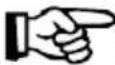
4.2 Overview of parts.... 27
5. Installation and operation.... 28
5.1 Assembly and Installation....28
5.2 Operating....31
6. Cleaning and maintenance 34
6.1 Cleaning 34
6.2 Maintenance....34
7. Possible Malfunctions.... 35
Bartscher GmbH
Read these instructions before using and keep them available at all times!
This instruction manual contains information about the installation, operation and maintenance of the device and should be consulted as an important source of information and reference guide. Awareness of the safety instructions and instructions for use in this manual will ensure the safe and correct use of the device.
In addition to the information given here, you should comply with any local Health and safety Controls and generally applicable safety regulations.
The instruction manual forms part of the product and should be kept near the device and easily accessible for anyone carrying out the installation, servicing, maintenance or cleaning.
1. Safety
This device is designed in accordance with the presently applicable technological standards. However, the device can pose a danger if handled improperly and inappropriately.
All people using the device should follow the instructions and tips contained in these instructions.
1.1 Safety instructions
• Always change the gas cylinder in a well ventilated area, away from any inflammation sources.
- The cylinder must always be stored outdoors or in a well ventilated area.
- Indoor storage of this appliance is permissible only if gas cylinder is disconnected and removed from the appliance.
- Do not attempt to alter the appliance in any manner. Do not paint the radiant screen, control panel or reflector.
- The appliance must be installed and gas cylinder stored in accordance with local gas fitting regulations.
- Shut off the valve at the gas cylinder or the regulator before moving the appliance.
- Use only the type of gas specified by the manufacturer.
- Check that the regulator seal is correctly fitted and able to fulfil its function.
- Close the gas supply at the valve of the gas cylinder or the regulator after use.
- Do not use this appliance until all connections have been leak tested.
- In the event of gas leakage, the appliance shall not be used or if alight, the gas supply shall be shut off and the appliance shall be investigated and rectified before it is used again.
- Shut off and check heater immediately if any of the following conditions occur:
The smell of gas in conjunction with extreme yellow tipping of the burner flames.
Heater does not reach a proper temperature. A temperature less than 50 °C will cause restricted heat flow and the appliance will not work properly.
The appliance starts making popping noises during use (a slight popping noise is normal when the appliance is extinguished).
- Any guard or other protective device removed for servicing the heater must be replaced before operating the heater.
- Danger of burns! Children and adults should be warned of the hazards of high surface temperatures and should stay away to avoid burns or clothing ignition.
- Young children and pets should be carefully supervised when they are in the area of the heater.
- Fire hazard! Do not ever place cloths, blankets or other inflammable objects against or over the patio heater. Do not place any inflammable objects near the patio heater. Always obey the minimum clearance to combustible materials.
- Certain material or items when stored under or near this appliance will be exposed to radiant heat and could be seriously damaged.
- Do not spray aerosols in the vicinity of this appliance while it is in operation.
- Do never touch the device with moisten or wet hands.
- Do not use the device if it does not function properly, has been damaged or dropped.
- Do not use any accessory or spare parts that have not been recommended by the manufacturer. These can be dangerous for the user, or lead to damage of the device or personal injury, and furthermore invalidate the warranty.
- Do not tip over the device.
- Do not expose the device to bad weather conditions (storm, rain, snow, thunder storm, etc.).
1.2 Key to symbols
In this manual, symbols are used to highlight important safety instructions and any advice relating to the device. The instructions should be followed very carefully to avoid any risk of accident, personal injury or material damage.

DANGER!
This symbol highlights hazards which could lead to injury.
To avoid them please follow the instructions very carefully and proceed with particular attention in these cases.

WARNING!
This symbol highlights dangerous situations which could lead to injury or death.
To avoid them please follow the instructions very carefully and proceed with particular attention in these cases.

CAUTION!
This symbol highlights dangerous situations which could lead to light injuries, or damage, malfunction, and/or destruction of the device.
To avoid them please follow the instructions very carefully and proceed with particular attention in these cases.
NOTE!
This symbol highlights recommendations and information aimed for effective and trouble-free device operation.
1.3 Intended use

WARNING!
For outdoor use only!
The use of this appliance in enclosed areas can be dangerous and is PROHIBITED!

CAUTION!
The provided pressure controller is meant for private use only!
According to BGV D34 (VBG 21) and TRF 96, commercial use (e. g. fun fairs, Cafés) requires a hose breaking protection according to DIN 30 693 „Hose breaking protection for liquefied gas systems“ and a safety pressure controller with manometer.
Hose breaking protection and safety pressure controller are not part of shipment!
Safe operation can only be guaranteed when using the device for its intended purpose.
Any technical interventions, as well as assembly and maintenance are to be made by a qualified customer service only.
The gas patio heater is meant for use in street cafés, balconies and terraces only.
Do not use the gas patio heater for:
- Drying of clothes;
- Heating of rooms.

CAUTION!
Any use going beyond the intended purpose and/or any different use of the device is forbidden and is not considered as conventional.
Any claims against the manufacturer or his authorized representative as a consequence of experiencing damages resulting from unconventional use are impossible.
The operator is liable for all damages resulting from inappropriate use.
2. General information
2.1 Liability and Warrantees
All the information and instructions in this manual take into account standard safety regulations, current levels of technical engineering as well as the expertise and experience we have developed over the years.
The instruction manual was translated with all due care and attention. However, we do not accept liability for any translation errors. The German version of this instruction manual is definitive.
If the delivery consists of a special model, the actual scope of delivery may differ from the descriptions and illustrations in this manual. This is also the case for special orders or when the device has been modified in line with new technology.
NOTE!
Read this manual carefully and thoroughly before any operation of the device, and especially before turning it on!
Manufacturer is not liable for any damages or faults caused by:
- violation of advice concerning operation and cleaning;
- use other than designed;
- alterations made by user;
- use of inadequate spare parts.
We reserve the right to make technical changes for purposes of developing and improving the useful properties.
2.2 Copyright protection
The instruction manual including any texts, drawings, images or other illustrations is copyright. No part of this publication may be reproduced, transmitted or used in any form or by any means without permission in writing from the manufacturer. Any person who commits any unauthorized act in relation to this publication shall be liable to claims for damages. All rights reserved.

NOTE!
The contents, texts, drawings, pictures and any other illustrations are copyright and subject to other protection rights. Any person unlawfully using this publication is liable to criminal prosecution.
2.3 Declaration of conformity

The device complies with the current standards and directives of the EU. We certify this in the EC declaration of conformity. If required we will be glad to send you the according declaration of conformity.
3. Transport, packaging and storage
3.1 Delivery check
Please check the delivery upon completeness and transport damage immediately after receipt. In case of visible damage do not accept or accept the delivery with reservation only.
Note the extent of damage on the carrier's bill of delivery. Trigger off the complaint.
Hidden damages should be reclaimed immediately after notice, as claims for damages can only be asserted within the effective period for complaints.
3.2 Packaging
Please do not throw away the covering carton of your device as it might be useful for storage purposes, when moving or, in case of damages, when the device must be sent back to a repair center. The outer and inner packing material should be removed completely from the device before installation.
NOTE!
If you liked to dispose the packing, consider the regulations applicable in your country. Supply re-usable packing materials to the recycling.
Please inspect the device upon completeness. In case any part is missing please contact our customer service center immediately.
3.3 Storage
Keep the package closed until installation and under consideration of the outside indicated positioning- and storage markings.
Packages should be stored under consideration of the following:
- Do not store outdoors.
- Keep it dry and dust-free.
- Do not expose it to aggressive media.
- Do not expose it to direct sunlight.
- Avoid mechanical shocks and vibration.
- In case of longer storage (> 3 months) make sure you check the state of the packaging and the parts regularly. If required refresh or renew.
Storage during periods of extended inactivity or when transporting:
! CAUTION!
There is no limitation on the storage of the appliance indoors (house/garage) provided that the cylinder is removed from the appliance.
Procedure:
- Turn control knob „0“.
- Turn gas cylinder control „OFF“.
- Disconnect gas cylinder and move to a secure, well ventilated location outdoors. DO NOT store in a location that will exceed 50 °C.
- Store heater upright in an area sheltered from direct contact with dust, debris or penetrating water (such as rain, sleet, hail, snow), in order to avoid the air passages from getting dusty or building up water.
- Cover the device in order to protect the surfaces.
! CAUTION!
Wait until heater is cool before covering.
4. Technical data
4.1 Technical specification
| Description Gas patio | heater, mobile |
| Item no.: | 825131 |
| Model: Stainless steel | |
| Gas type: Propane, Butane, mix | |
| Power: 13,5 kW/h | |
| Dimensions: Height: 2.220 mm, aluminium reflector: ∅ 780 mm | |
| Weight: 18 Kg | |
We reserve the right to modifications!
4.2 Overview of parts
- 5pcs bolts M5*12 and 5pcs washers for rear panel of housing and base.
- 5pcs bolts M5*12 and 5pcs washers for rear panel of housing and housing lid.
- 4pcs bolts M5*12 and 4pcs washers for the post and housing lid.
• 3pcs wing nuts and 3pcs big washers for reflector. -
3pcs bolts M5*12 and 3pcs washers for main burner and the post.
-
Reflector
- Burner screen
- Lower burner tray
- Lower screen cone assembly
- Main post
- Housing lid
- Rear panel housing
- Optional wheels
- Base
- Door
- Lock
- Bolts
- Washers
- Big washers
- Wing nut
- Lock
- Plastic cover
- Inner Pipe
natural_image
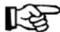
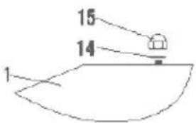
Technical line drawing of a mechanical component with an inset view showing internal components (no text or symbols)Fig. 1 Fig. 2
5. Installation and operation
5.1 Assembly and Installation
Required Tools:
• Philip Screwdriver / Adjustable Spanners / Wrenches.
- Leak Detection Solution one part detergent and three parts water.
- Before assembly, make sure all packing material and any transmit protection has been removed.
- Assemble all nuts and bolts loosely at first. Tighten all connections after completion of assembly. This eases your work and increases the stability of your appliance.
- Small deviations in equipment may occur. This is no lack of quality but subject to improvements.
Assembly
STEP 1:
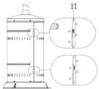
Screw rear panel of housing to the base with 5pcs bolts M5*12 and 5pcs washer. (Detail Fig. A)
STEP 2:
Push the housing lid over rear panel of housing and place onto rear panel of housing. Screw together the housing lid and rear panel of housing with 5pcs bolts M5*12 and 5pcs washers. (Detail Fig. B)
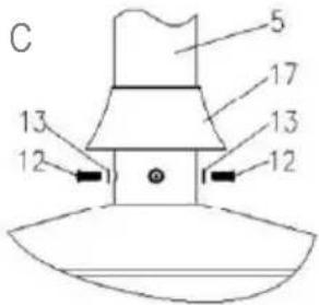
STEP 3:
Fixing the post upwards onto the housing lid with 4pcs bolts M5*12 and 4pcs washers, then put plastic cover through the post. (Detail Fig. C)
Detail Fig. A
Detail Fig. B
Detail Fig. C
STEP 4:
Place the reflector to main burner using 3pcs wing nuts and 3pcs washers. (Detail Fig. D)
STEP 5:
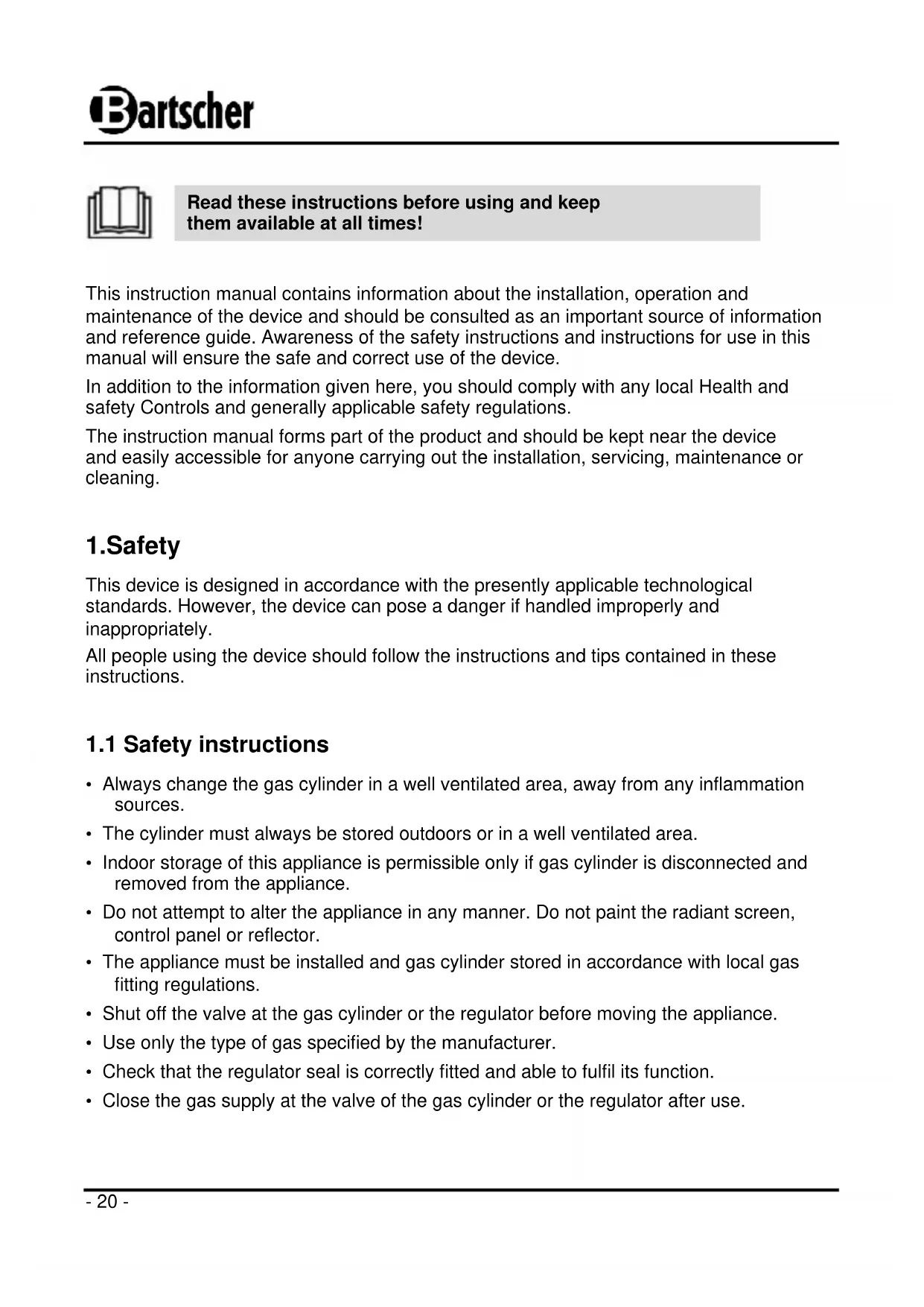
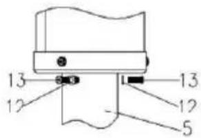
Tighten inner gas pipe (16) to main burner (See Fig. 2). Then fix main burner to the post with 3 bolts M5*12 and 3pcs washers. (Detail Fig. E)
STEP 6:
Fix the door to housing. (See Fig. 1 and Detail Fig. F)
Detail Fig. D
Detail Fig. E
Detail Fig. F
Optional base stand
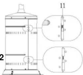
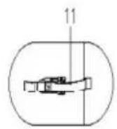
Base stand assembly parts: 6pcs bolts M5*12 and 6pcs washers for base stand and base. Attach 3 pcs stands to the base.
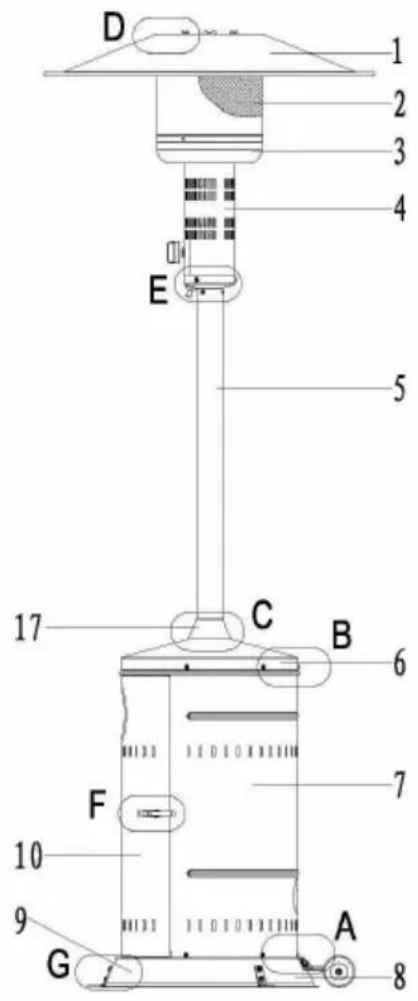
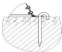
Use supplied hooks/bolts to insert them into the ground or floor through base stand holes for appliance stability. (See Fig. 3 Detail Fig. G).
Detail Fig. G
natural_image
Diagram of a pipe or tube inserted into a container with a spring, showing no text or symbols.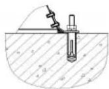
natural_image
Technical diagram of a mechanical assembly with a cylindrical component inserted into a circular housing (no text or labels)Fig. 3
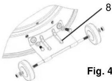
Optional wheels
Wheels assembly parts: 4pcs bolts and 4pcs washers for wheels assembly.
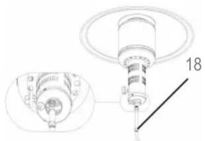
Collect wheels parts together and fix wheels to the base. (See Fig. 4)
natural_image
Technical line drawing of a mechanical component with labeled parts (no readable text or symbols)Installation

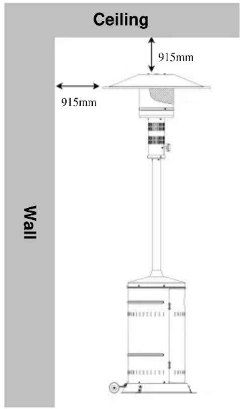
WARNING! Danger of burn!
Do not move this appliance when in operation, or after it has been turned off before the temperature has cooled down.
• Always position the appliance on a firm level surface.
- Not at any time should you place the device on an inflammable surface.
- You must not position the device near open fireplaces, electric ovens/arc furnaces, furnaces/electric heaters or other heat sources.

WARNING! Fire Danger!
Do not use or store flammable materials near this appliance. Keep a safe distance to all sides of the device.
- Do not place any objects on or against this appliance.
- Always maintain at least 915 mm clearance between heater and walls, ceiling and other materials. (see figure to the right)
- Make sure, the device stands secure so it does not tilt from strong wind.
- The regulator & hose assembly must be positioned in a way, so that people cannot trip over and where they will not be subject to accidental damage.
- Do not place this device in passageways, in order to prevent the device from tilting.
- Do not obstruct the ventilation holes of the cylinder housing.
-
Keep controls, burner and ventilation openings clean. Signs of possible blockage include:
-
Gas odour and yellow, leaking flames.
- Heater does not reach the desired temperature.
■ Heater glow is excessively uneven.
■ Heater makes popping noises.
5.2 Operating
GASREQUIREMENTS
• Gas connections and hose assembly must conform to local safety regulations.
- Never use a gas cylinder with a damaged body, valve, collar, or foot ring. A dented or rusty gas tank may be hazardous and should be checked out by a gas supplier.
- Never connect this appliance to an unregulated gas source.
- When the appliance is not in use, turn the gas cylinder „OFF“.
CONNECTING TO A GAS CYLINDER
- Use 9 kg gas cylinder. Please refer to your gas supplier for suitable gas cylinder.
• Refer to your gas supplier for instructions on the use of your gas cylinder.

WARNING! Fire Danger!
Only change gas cylinders outdoors or in a well ventilated area away from naked flames and any other source of ignition.
• The gas cylinder must always be used in an upright position.
- Close the heater control knob by turning it fully clockwise.
- Close the gas cylinder tap and then attach the regulator onto the gas cylinder.
- Tighten all connections firmly and with a spanner where appropriate. The cylinder should be placed on the cylinder base.
- Check for leaks at all joints using a soap/water solution. If a leak is found, tighten the joint and then retest.

CAUTION!
Before first use and after every gas cylinder change, gas delivery system must be purged of air before igniting! To do so, turn the control knob anticlockwise to „”. Press knob and hold for 3 minutes before attempting ignition.
HOW TO LIGHT THE PILOT
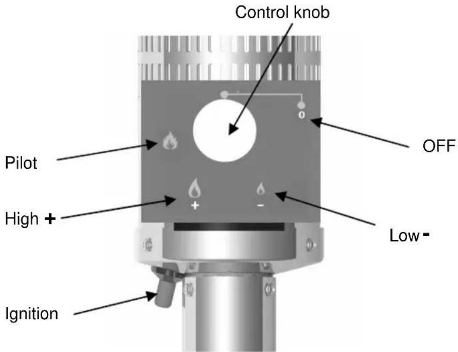
- Check all connections prior to each use.
- Turn on main gas supply at source.
- Press to turn control knob anti-clockwise to ,, 🎨“ (see picture above).
- Hold knob depressed, press Ignition button repeatedly until pilot flame is lit, then continue to hold the knob depressed for 10 seconds until the pilot remains lit after releasing knob.
- If pilot fails to ignite, press to turn knob clockwise to "0" and repeat
HOW TO LIGHT THE PATIO HEATER
• The pilot should be lit and the knob set to „
- Hold knob depressed gently and turn anti-clockwise to „+“.
- When mesh glows lit, turn knob clockwise from „+“ to „-“ as required.

NOTE!
The burner may be noisy when initially turned on. To eliminate excessive noise from the burner, turn the control knob to „”. Then turn the knob to desired heat level.
RELIGHTING
- Turn control knob to „0“.
- Wait at least 5 minutes, to let gas dissipate, before attempting to re-light pilot.
- Repeat steps mentioned in part „How to light the patio heater”.
EXTINGUISH
- Hold knob depressed lightly & turn the knob clockwise to „0“.
- Close the valve of the gas cylinder or the regulator after use.

NOTE!
Close the gas regulators after use and allow this appliance to cool before moving the appliance.
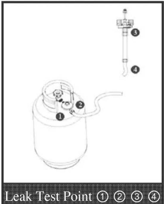
GAS LEAK TESTING

CAUTION!
Never use a naked flame to check for leaks! Never smoke while leak testing!
- The gas connections on this appliance are leak tested at the factory prior to shipment.
- This appliance needs to be periodically checked for leaks and an immediate check is required if the smell of gas is detected.
- Make a soap solution using 1 part of liquid dish-washing soap to 3 parts water. The soap solution can be applied with a soap bottle, brush, or rag to the leak tested points shown in the figure to the right.
- The valve of the gas cylinder should be in the „OFF“ position at this point of the leak test. Once the soapy solution is applied to the gas connections, the valve of the gas cylinder needs to be turned to the „ON“ position.
- Soap bubbles will begin to form in the soapy solution if a leak is present.
- In case of a leak, turn off the gas supply. Tighten any leaking fittings, then turn the gas supply on and recheck.
6. Cleaning and maintenance
6.1 Cleaning

CAUTION!
The device is not suited for direct washing via water jets. Therefore, you must not use any kind of pressure water jet for cleaning the device!
- Let device cool off before cleaning or repairing.
- Keep exterior surfaces clean.
Use warm soapy water for cleaning. Never use flammable or corrosive cleaning agents.
○ While washing your unit, be sure to keep the area around the burner and pilot assembly dry at all times. If the gas control is exposed to water in any way, never try to use the heater. The gas control must be replaced.
- Spiders and insects can nest in burner or orifices. This dangerous condition can damage the heater and render it unsafe for use. Clean burner holes by using a heavy duty pipe cleaner. Compressed air may help clear away smaller particles.
○ Carbon deposits may create a fire hazard. If any carbon deposits develop, clean dome and engine with warm soapy water.

NOTE!
In a salt-air environment (such as near the sea), corrosion occurs more quickly than normal. Frequently check the corroded areas and repair them promptly.
○ Only use a soft cloth and make sure you never use any kind of abrasive agents or pads which could scratch the surface.
o Make sure the device has been cleaned properly before storing it in a dry place.
6.2 Maintenance
- Check the tubing or the flexible hose once a month and each time the cylinder is changed.
- The tubing or the flexible hose must be changed within one year.
- The hose assembly must be replaced prior to the appliance being put into operation if there is evidence of excessive abrasion or wear, or if the hose is damaged. For replacement, use hose assembly specified by the manufacturer only.
The heater should be inspected before use and at least annually by a qualified service person. More frequent cleaning may be required as necessary. It is imperative that control compartment, burners and circulating air passageways of the appliance are kept clean.
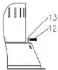
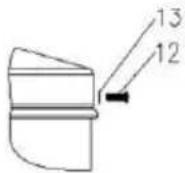
- Possible Malfunctions
| PROBLEM CAUSE SOLUTION | ||
| Pilot won't light | Cylinder valve is closed Open valve | |
| Blockage in orifice or pilot tube | Clean or replace orifice or pilot tube | |
| Air in the gas line | Open gas line and bleed it (pressing control knob in) for not more than 1-2 minutes or until you smell gas | |
| Low gas pressure Gas cylinder low or empty | ||
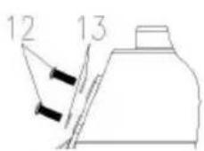
| Igniter fails | Use match to light pilot, and obtain new igniter and replace. (See pictures page 36) | |
| Pilot won't stay lit | Dirt build up around pilot Clean dirt from around pilot | |
| Connection between gas valve and pilot assembly is loose | Tighten connection and perform leak test | |
| Burner won't light | Gas pressure is low Replace gas cylinder | |
| Control knob is not in „ON“ position | Turn control knob to „ON“ position | |
| Burner flame is lowNote: Do not operate heater below 50 °C (40°F) | Gas pressure is low Replace gas cylinder | |
| Outdoor temperature is greater than 50 °C (40°F) and tank is less than 25% full | Replace gas cylinder | |
| Supply hose is interrupted (e.g. bent hose) | Resolve interruption and perform leak test on hose | |
| Emitter glows unevenNote: Normally it does not glow 2.5 cm below the emitter | Gas pressure is low Replace gas cylinder | |
| Base is not on a level surface | Place heater on a level surface | |
| Heater not level Level heater | ||
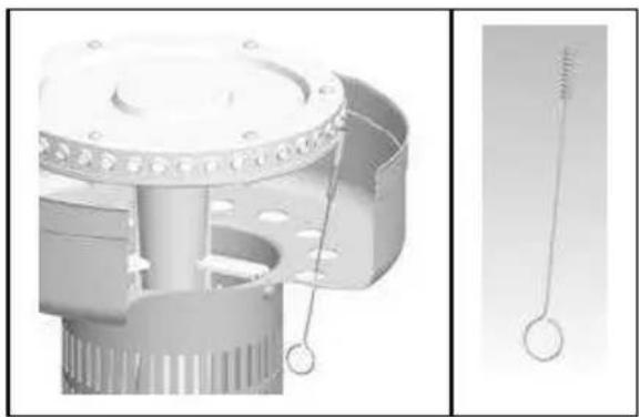
natural_image
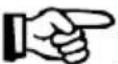
Technical illustration of a mechanical component with internal parts and a close-up view of a rod-like structure (no text or symbols)If for some reasons your ignition fails to deliver a spark, the heater can be started by inserting a lit match using supplied match holder through the burner hole (see left photo) while pushing the control knob into „” position.
Bartscher GmbH
4.1 Indications techniques
natural_image
Technical line drawing of a mechanical component with an inset view showing internal structure (no text or symbols)fig. 1
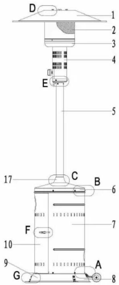
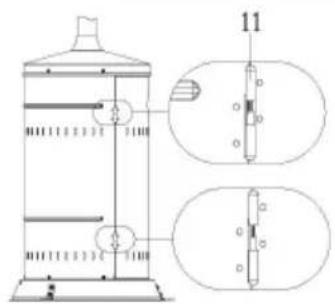
fig. 2
natural_image
Diagram of a pipe with a submerged object, no text or symbols present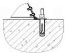
natural_image
Technical diagram of a mechanical assembly with a bolt and rod inserted into a circular component (no text or labels)Fig. 3
Roues facultatives
natural_image
Technical line drawing of a mechanical assembly with labeled parts (no text or symbols beyond label)Mise en service

5.2 Utilisation
RECOMMANDATIONS GAZ
natural_image
Technical illustration of a mechanical component with internal gears and a spring-like spring, shown in two views (no text or symbols)


- Optionale Rollen
- Bedienung
- of the original instruction manual
- Safety....20
- General information 24
- Transport, packaging and storage.... 25
- Technical data.... 26
- Installation and operation.... 28
- Cleaning and maintenance 34
- Possible Malfunctions.... 35
- Read these instructions before using and keep them available at all times!
- Safety
- Safety instructions
- Key to symbols
- DANGER!
- WARNING!
- CAUTION!
- NOTE!
- Intended use
- General information
- Liability and Warrantees
- Copyright protection
- Declaration of conformity
- Transport, packaging and storage
- Delivery check
- Packaging
- Storage
- ! CAUTION!
- Procedure:
- Technical data
- Technical specification
- Overview of parts
- Installation and operation
- Assembly and Installation
- Required Tools:
- Assembly
- STEP 1:
- STEP 2:
- STEP 3:
- STEP 4:
- STEP 5:
- STEP 6:
- Optional base stand
- Optional wheels
- Installation
- WARNING! Danger of burn!
- WARNING! Fire Danger!
- Operating
- GASREQUIREMENTS
- CONNECTING TO A GAS CYLINDER
- HOW TO LIGHT THE PATIO HEATER
- RELIGHTING
- EXTINGUISH
- GAS LEAK TESTING
- Cleaning and maintenance
- Cleaning
- Maintenance
- Indications techniques
- Roues facultatives
- Mise en service
- Utilisation
- RECOMMANDATIONS GAZ
Brand : BARTSCHER
Model : 825131
Category : Heating