DKI 90601 - Basket Elektra Bregenz - Free user manual and instructions
Find the device manual for free DKI 90601 Elektra Bregenz in PDF.

| Product type | Kitchen hood (extracting or recirculating) |
| Brand | Elektra Bregenz |
| Model | DKI 90601 |
| Usage | Extracting version (external exhaust) or recirculating version (indoor recirculation with charcoal filters) |
| Installation | Ceiling mounting (island hood), telescopic structure with adjustable height |
| Exhaust connection | Diameter 150 mm (flexible hose not supplied) |
| Electrical supply | 220-240 V ~ 50 Hz (class II, double insulation, no earth) |
| Motor power | Not specified (refer to rating plate) |
| Motor speeds | 3 speeds + intensive function (10 minutes) |
| Lighting | Integrated (bulb not specified, use only during cooking) |
| Timer | Automatic switch-off after 15 minutes |
| Clean Air function | Automatic operation 10 minutes per hour at speed 1 (active when hood is off) |
| Saturation indicator | Flashing display (F for grease filter, A for charcoal filter) |
| Grease filters | Washable (metal or acrylic), wash every 2 months (dishwasher safe for metal) |
| Charcoal filters | Not washable, replace every 4 months (in recirculating version) |
| Minimum safety distance | 65 cm between the cooking surface and the lowest part of the hood |
| Safety | Do not cook with flame, disconnect before maintenance, provide ventilation if used simultaneously with combustion appliances |
| Noise level | Not specified |
| Dimensions (approx.) | Not provided (telescopic structure, adjustable height) |
| Supplied accessories | Manual, drilling template, fixing screws, connection flange (depending on version) |
| Repairability | Spare parts available: filters, power cable, bulbs (contact customer service) |
Frequently Asked Questions - DKI 90601 Elektra Bregenz
User questions about DKI 90601 Elektra Bregenz
0 question about this device. Answer the ones you know or ask your own.
Ask a new question about this device
Download the instructions for your Basket in PDF format for free! Find your manual DKI 90601 - Elektra Bregenz and take your electronic device back in hand. On this page are published all the documents necessary for the use of your device. DKI 90601 by Elektra Bregenz.
USER MANUAL DKI 90601 Elektra Bregenz
Fig.4
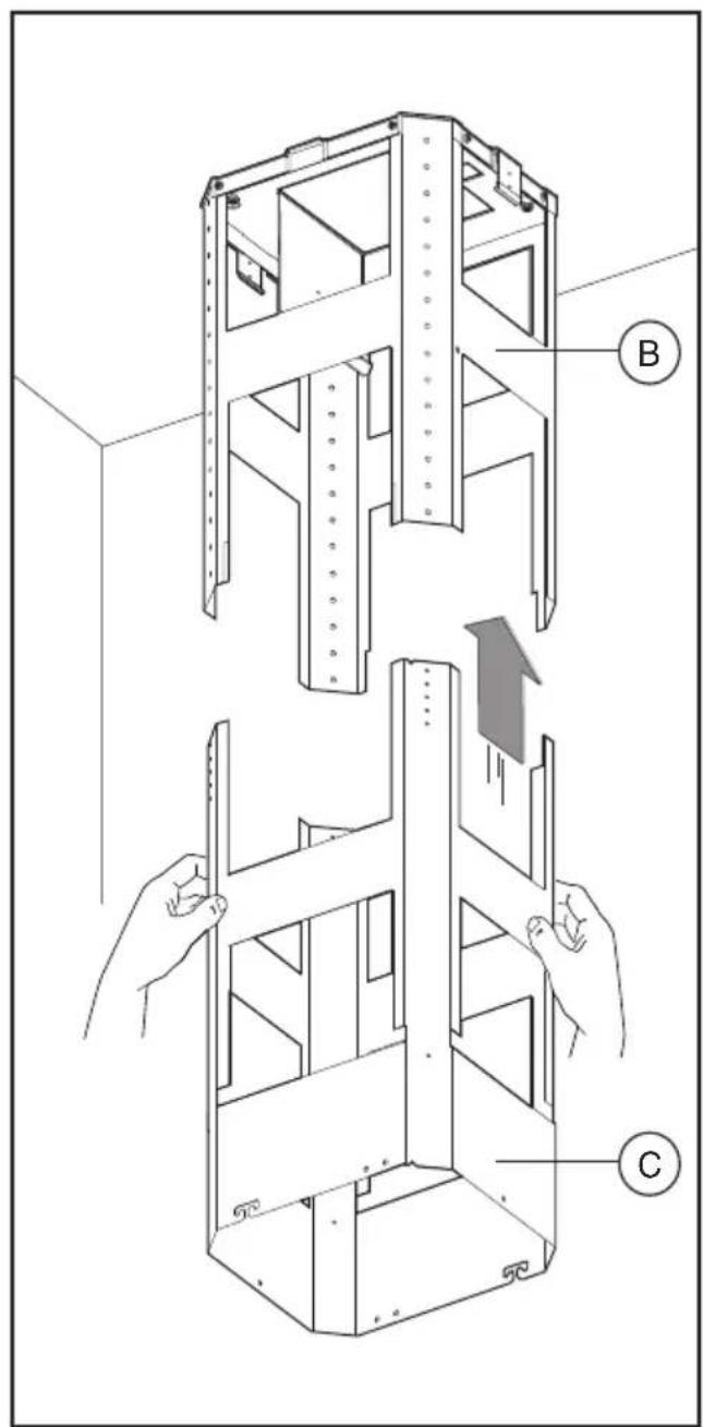
Fig.5 Fig.6
natural_image
Technical illustration of a mechanical assembly with hands operating a coiled spring component (no text or symbols present)Fig.7 Fig.8
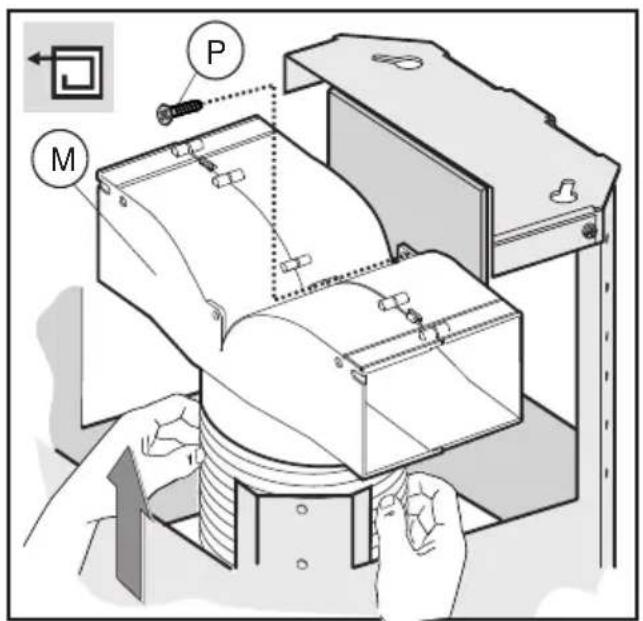
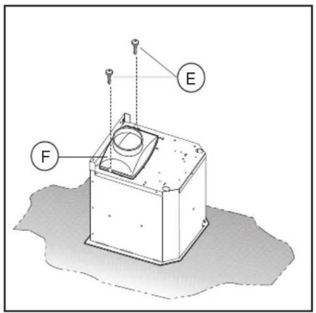
Fig.9
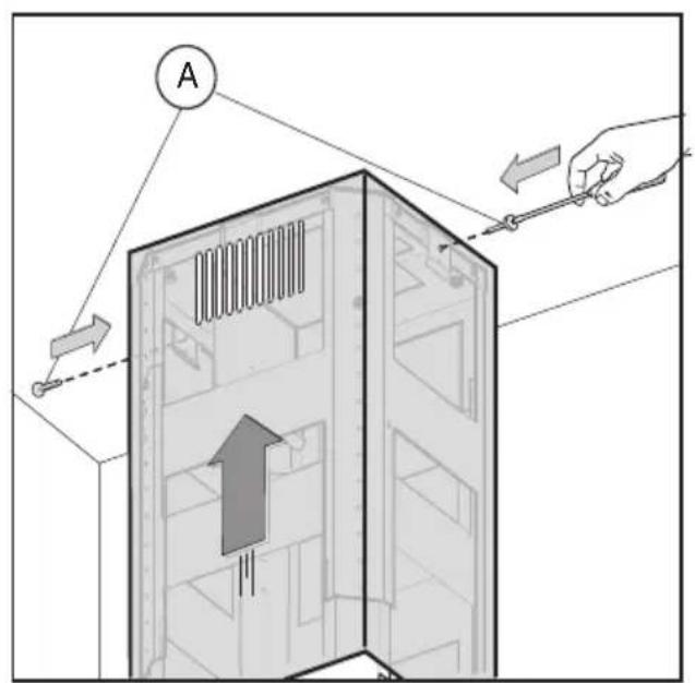
Fig.10
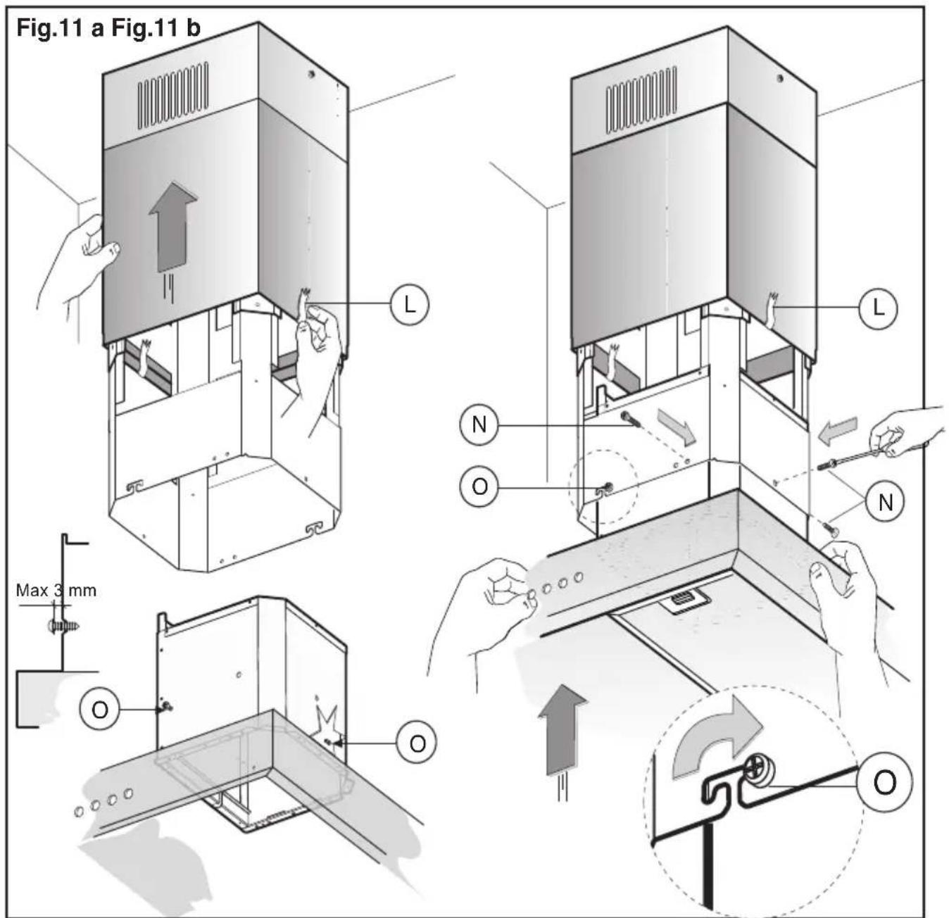
Fig.11
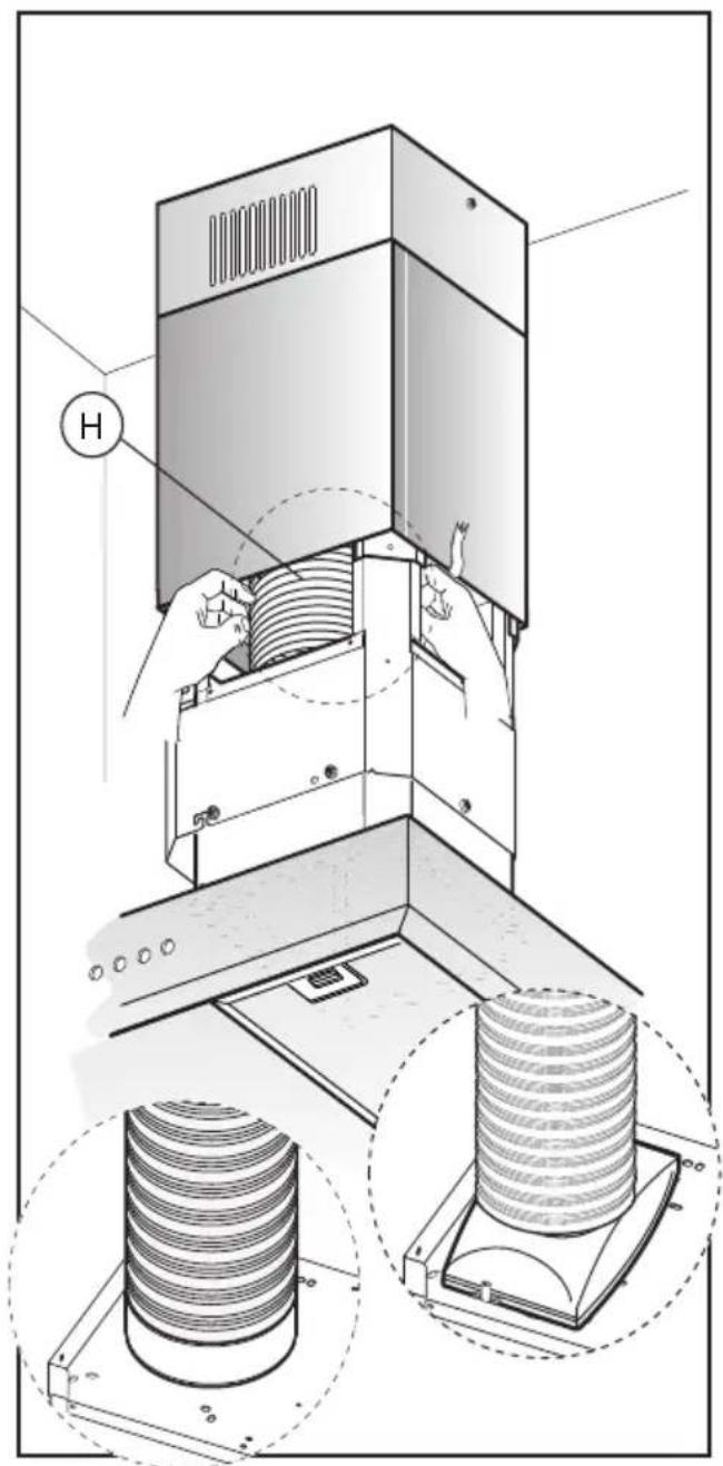
Fig.12
natural_image
Illustration of a vertical elevator with a downward arrow indicating airflow or cooling (no text or symbols present)Fig.13
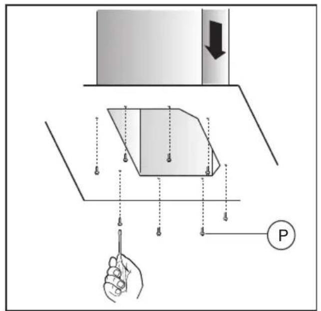
Fig.14
natural_image
Illustration of a hand holding a flatboard with a curved lid, showing internal components (no text or symbols)Fig.16 Fig.17
natural_image
Technical line drawing of a mechanical component with a magnified inset showing a hand interacting with a bracket (no text or symbols)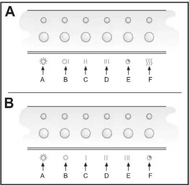
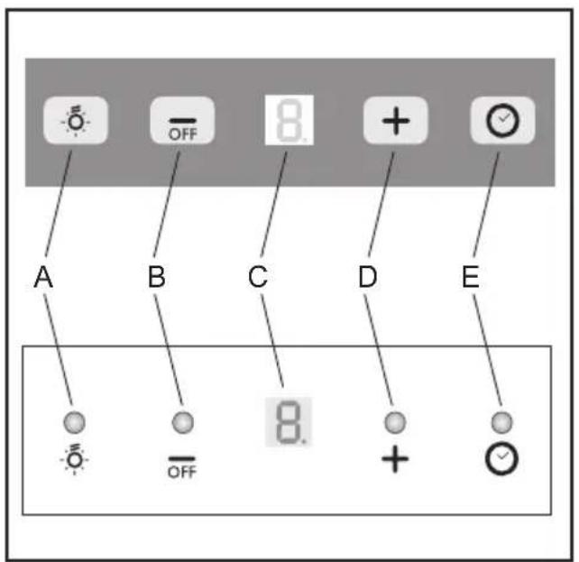
Fig.18 Fig.19
flowchart
graph TD
    subgraph A
        A1["●"] --> A2["○"]
        A2 --> A3["1"]
        A3 --> A4["2"]
        A4 --> A5["3"]
        A5 --> A6["▽"]
        A1 --> G["G"]
        A2 --> B["B"]
        A3 --> C["C"]
        A4 --> D["D"]
        A5 --> E["E"]
        A6 --> A["A"]
    end
    subgraph B
        B1["○"] --> B2["○ 0"]
        B2 --> B3["○ 1"]
        B3 --> B4["○ 2"]
        B4 --> B5["○ 3"]
        B5 --> B6["▽"]
flowchart
graph TD
    1 --> A
    0 --> B
    1 --> C
    2 --> D
    3 --> E
    5 --> F
Fig.20 Fig.21
GENERALITÀ
Carefully read the following important information regarding installation safety and maintenance. Keep this information booklet accessible for further consultations.
The appliance has been designed for use in the ducting version (air exhaust to the outside – Fig.1B), filtering version (air circulation on the inside – Fig.1A) or with external motor (Fig.1C).
SAFETY PRECAUTION
- Take care when the cooker hood is operating simultaneously with an open fireplace or burner that depend on the air in the environment and are supplied by other than electrical energy, as the cooker hood removes the air from the environment which a burner or fireplace need for combustion. The negative pressure in the environment must not exceed 4Pa (4x10⁻⁵ bar). Provide adequate ventilation in the environment for a safe operation of the cooker hood.
Follow the local laws applicable for external air evacuation.
Before connecting the model to the electricity network:
- control the data plate (positioned inside the appliance) to ascertain that the voltage and power correspond to the network and the socket is suitable. If in doubt ask a qualified electrician.
- If the power supply cable is damaged, it must be replaced with another cable or a special assembly, which may be obtained direct from the manufacturer or from the Technical Assistance Centre.
2. WARNING!
In certain circumstances electrical appliances may be a danger hazard.
A) Do not check the status of the filters while the cooker hood is operating
B) Do not touch bulbs or adjacent areas, during or straight after prolonged use of the lighting installation.
C) Flambè cooking is prohibited underneath the cooker hood
D) Avoid free flame, as it is damaging for the filters and a fire hazard
E) Constantly check food frying to avoid that the overheated oil may become a fire hazard
F) Disconnect the electrical plug prior to any maintenance.
G) This appliance is not intended for use by young children or infirm persons without supervision
H) Young children should be supervised to ensure they do not play with the appliance
I) There shall be adequate ventilation of the room when the rangehood is used at the same time as appliances burning gas or other fuels
L) There is a risk of fire if cleaning is not carried out in accordance with the instructions
This appliance conforms to the European Directive EC/2002/96, Waste Electrical and Electronic Equipment (WEEE). By making sure that this appliance is disposed of in a suitable manner, the user is helping to prevent potential damage to the environment or to public health.
The symbol on the product or on the accompanying paperwork indicates that the appliance should not be treated as domestic waste, but should be delivered to a suitable electric and electronic appliance recycling collection point. Follow local guidelines when disposing of waste. For more information on the treatment, re-use and recycling of this product, please contact your local authority, domestic waste collection service or the shop where the appliance was purchased.
INSTALLATION INSTRUCTIONS
Assembly and electrical connections must be carried out by specialised personnel.
• Electric Connection
The appliance has been manufactured as a class II, therefore no earth cable is necessary.
The connection to the mains is carried out as follows: BROWN = L line
BLUE = N neutral
If not provided, connect a plug for the electrical load indicated on the description label. Where a plug is provided, the cooker hood must be installed in order that the plug is easily accessible.
An omnipolar switch with a minimum opening of 3mm between contacts, in line with the electrical load and local standards, must be placed between the appliance and the network in the case of direct connection to the electrical network.
- The minimum distance between the support surfaces of the cooking pots on the cooker top and the lowest part of the cooker hood must be at least 65 cm.
If a connection tube composed of two parts is used, the upper part must be placed outside the lower part.
Do not connect the cooker hood exhaust to the same conductor used to circulate hot air or for evacuating fumes from other appliances generated by other than an electrical source.
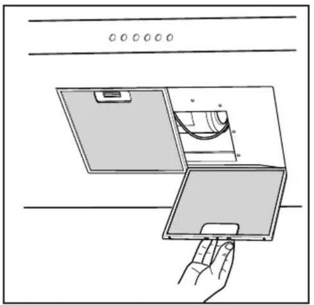
Before proceeding with the assembly operations, remove the anti-grease filter(s) (Fig.16) so that the unit is easier to handle.
In the case of assembly of the appliance in the suction version prepare the hole for evacuation of the air.
- We recommend the use of an air exhaust pipe with a diameter of 150. If a pipe with a smaller diameter is used, the efficiency of the product may be reduced and its operation may become noisier
- Hood assembly
Remove the structure from the packaging and remove the 2 screws A to separate the upper part from the lower part (fig.2).
- Position hole template on the ceiling paying attention
that the arrow is positioned on the same side as the appliance controls (Fig.3).
Make 4, ∅8 holes in the ceiling and drive in 3 screws without completely tightening them. Pay attention not to insert the screw into the hole marked with an X on the hole template (the screws and expansion plugs must be suitable for the type of wall).
- Take the upper part of the structure B (fig.4) and insert the 3 slots onto the 3 screws that are not completely tightened.
Rotate slightly to fit (fig.4).
Drive in the fourth screw X and tighten the remaining 3 to allow definitive blocking of the upper part of structure B
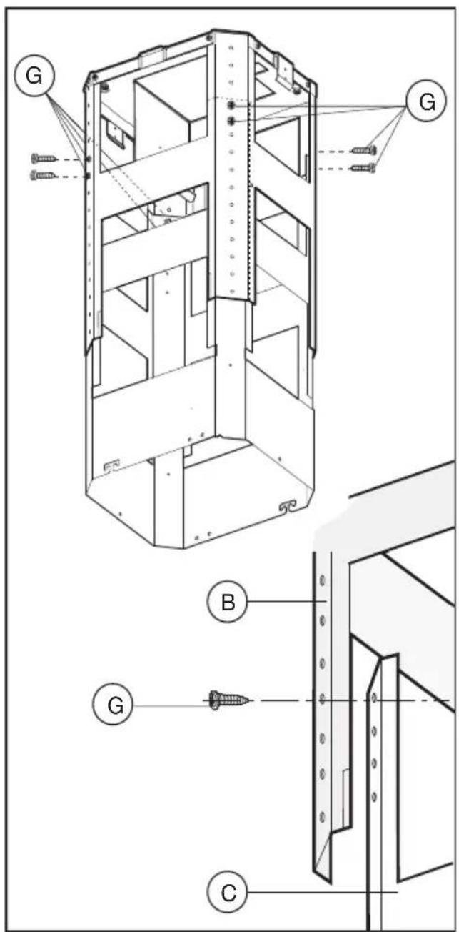
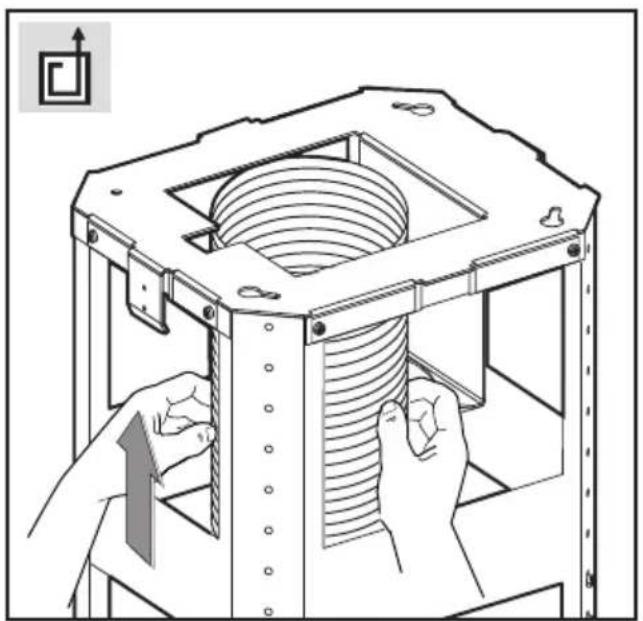
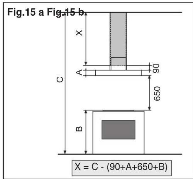
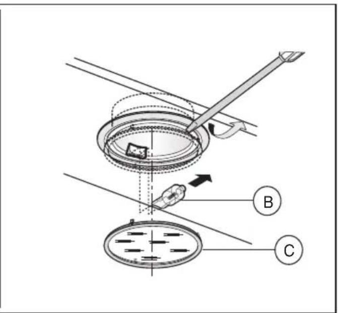
- Take the lower part of the telescopic structure C and insert it into the upper structure B (fig.5).
Adjust the height by referring to the amounts indicated in (fig.15) and block it using the 8 screws G that are supplied (fig.6).
- Suction version: fix the flexible pipe to the prepared air evacuation hole (fig 7).
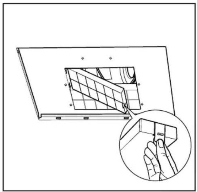
- Filtering version: fix the flexible pipe to the deflector M and fix screw I as indicated in (Fig.8), the active carbon filters must be applied to the suction unit positioned inside the hood (Fig.17).
- If your product is fitted with a connector flange, perform the assembly steps indicated in fig. 9 before fixing the cooker hood to the structure.
Take connector flange F and fit it to the upper part of the cooker hood suction assembly using the 2 screws E (fig. 9).
- Take the upper chimney piece and fix it to the structure using the 2 screws A (Fig.10).
Join the lower chimney piece with the upper one and fix it carefully using adhesive tape L (Fig.11a).
- Unscrew the 2 screws O, max 3 mm (Fig.11a). Insert the suction unit inside the structure paying attention that the previously unscrewed screws O, hook into the slots in the lower part as indicated in (Fig.11b).
Drive in the 3 screws N (supplied) and tighten the 2 screws O (Fig.11b).
- Fix the air evacuation pipe H (not supplied) onto the connection flange F (Fig.12)
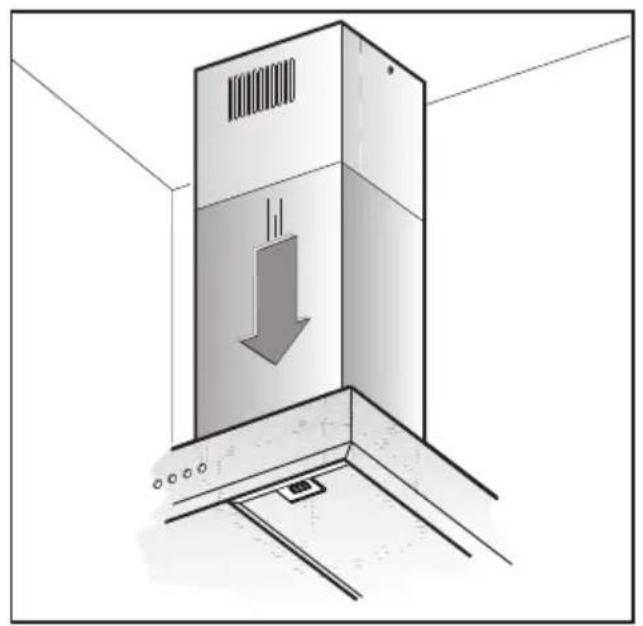
- Remove adhesive tape L and rest the lower chimney piece above the cooker hood (Fig.13).
-If the cooker hood is supplied with a lower chimney piece that must be fixed to the hood body with screws, remove the anti-grease filters from the hood by acting on the relevant handles (Fig.16). Then screw the lower chimney piece pipe to the inside of the hood, using screws P (Fig.14). Re-locate the filters in their seat.
USE AND MAINTENANCE
- We recommend that the cooker hood is switched on before any food is cooked. We also recommend that the appliance is left running for 15 minutes after the food is cooked, in order to thoroughly eliminate all contaminated air.
The effective performance of the cooker hood depends on constant maintenance; the anti-grease filter and the active carbon filter both require special attention.
- The anti-grease filter is used to trap any grease particles suspended in the air, therefore is subject to saturation
(the time it takes for the filter to become saturated depends on the way in which the appliance is used).
The acrylic filter, which is found resting on the grille, should be replaced when the text, visible through the grille, changes colour and the ink spreads; the new filter should be fitted in such a way that the text can be seen through the grille from outside the cooker hood.
If the filters do not have any text on them, or if metal filters or aluminium panel filters are used, they should be washed every 2 months in order to prevent the risk of fire. To wash the filters, proceed as follows:
- Remove the filter from the grille and wash it using a solution of water and neutral liquid detergent, leaving the dirt to soften.
- Rinse thoroughly with warm water and leave to dry. The metal filters and/or aluminium panel are also dishwasher safe. If the filters are made using aluminium, or if an aluminium panel is used, after a few washes the colour may change. This does not mean they have to be replaced.
If the replacement and washing instructions are not followed, the anti-grease filters may present a fire hazard.
- The active carbon filters are used to purify the air which is released back into the room. The filters are not washable or re-usable and must be replaced at least once every four months. The active carbon filter saturation level depends on the frequency with which the appliance is used, the type of cooking performed and the regularity with which the anti-grease filters are cleaned.
- Remove build-up from the fan and other surfaces of the cooker hood regularly using a cloth moistened with denatured alcohol or non-abrasive neutral liquid detergent.
- The light on the cooker hood is designed for use during cooking and not for general room illumination. Extended use of the light reduces the average duration of the bulb.
COMMANDS: (Fig.18)
Push-button A = on/off lights switch
Push-button B = on/off cooker hood switch. The appliance switches on at speed level 1, If the cooker hood is on depress the push-button for 2 sec. to switch off the cooker hood. If the cooker hood is at speed level 1 it will not be necessary to depress the push-button to switch the cooker hood off. Decreases the motor speed.
Display C = indicates the motor speed level selected and activates the timer.
Push-button D = switches on the cooker hood. Increases the motor speed. Touching the key at 3rd speed, the intensive function runs for 10', then the appliance go back to work at the original speed. During this function the display blinks.
Key E = The Timer times the functions on activation for 15 minutes, after which they are switched off. The Timer is deactivated by re-pressing Key E. When the Timer is activated the decimal point must flash on the display. The Timer cannot be activated if the intensive speed is functioning.
The “clean air” function is activated by pressing key E for 2 seconds when the appliance is switched off. This switches the motor on for 10 minutes every hour at the first speed. During functioning a rotary movement of the peripheral segments must be visualised on the display.
When this time has passed the motor switches off and the fixed letter “C” must be visualised on the display until the motor re-starts after 50 minutes for another 10 minutes and so on. Press any key apart from the light keys to return to normal functioning. Press key E to deactivate the function.
• Active carbon/grease filter saturation:Fig.18
- When display item C flashes, at a speed where it alternates with the letter F (e.g. 1 and F), the grease filters must be washed.
- When display item C flashes, at a speed where it alternates with the letter A (e.g. 1 and A), the carbon filters must be replaced.
After the clean filter has been positioned correctly, the electronic memory must be reset by pressing button A for approximately 5 seconds, until the indication F or A shown on the display C stops flashing.
• COMMANDS: ELECTRONIC (Fig.19 A):
$$ \begin{array}{l} \mathbf {A} = \text { LIGHT } \ \mathbf {B} = \text { OFF / SPEED I } \ \mathbf {C} = \text { SPEED II } \ \mathbf {D} = \text { S P E E D } \quad \text { I I I } \ \mathbf {E} = \text { AUTOMATIC STOP TIMER } - 1 5 \text { minutes } (*) \ \mathbf {F} = \text { FILTER SATURATION RESET LIGHT } \ \end{array} $$
When the “filter saturation” light flashes, the anti-grease filters must be washed. When the light comes on without flashing, the anti-grease filters must be washed and the carbon filters replaced (in case of operation whit the recycling version). When this operation has been completed, press the key to reset it.
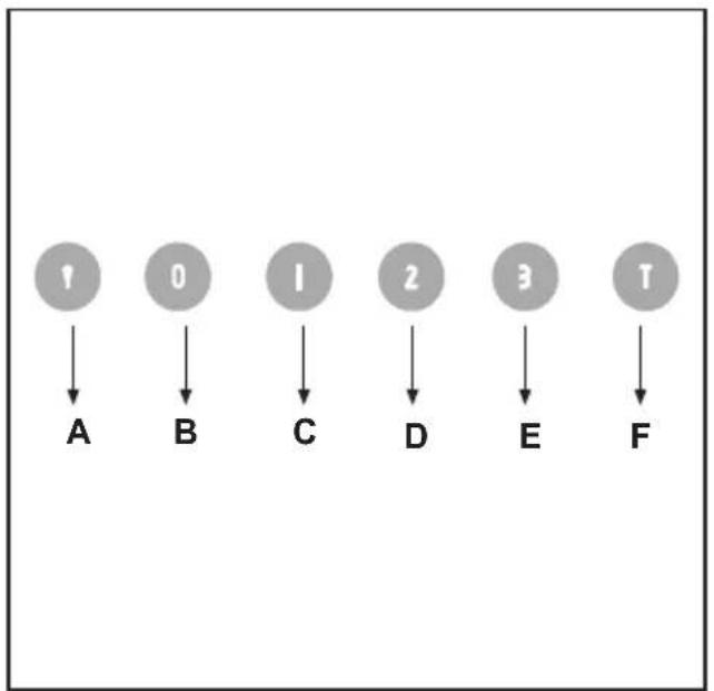
• COMMANDS:
(Fig.20) LUMINOUS
(Fig.19 B) ELECTRONIC the key symbols are explained below:
$$ \mathbf {A} = \text { LIGHT } $$
$$ \mathbf {B} = \text { O F F } $$
$$ \mathbf {C} = \text { S P E E D } I $$
$$ \mathbf {D} = \text { SPEED II } $$
$$ \mathbf {E} = \text { S P E E D } \quad \text { I I I } $$
$$ \mathbf {F} = \text { AUTOMATIC STOP TIMER } - 1 5 \text { minutes } (*) $$
- If your appliance does not have the INTENSIVE speed function, press key E for two seconds and it will be activated for 10 minutes after which it will return to the previously set speed. When the function is active the LED flashes. To interrupt it before the 10 minutes have expired press key E again.
- By pressing key F for two seconds (with the hood switched off) the “clean air” function is activated. This function switches the appliance on for ten minutes every hour at the first speed. As soon as this function is activated the motor starts up at the first speed for ten minutes, During this time key F and key C must flash at the same time.
After ten minutes the motor switches off and the LED of key F remains switched on with a fixed light until the motor starts up again at the first speed after fifty minutes and keys F and C start to flash again for ten minutes and so on.
By pressing any key for the exclusion of the hood light the hood will return immediately to its normal functioning (e.g. if key D is pressed the "clean air" function is deactivated and the motor moves to the 2nd speed straight away. By pressing key B the function is deactivated).
(*) The “automatic stop timer” delays stopping of the hood, which will continue functioning for 15 minutes at the operating speed set at the time this function is activated.
• Active carbon/grease filter saturation: Fig.19B / Fig.20
- When button A flashes at a frequency of 2 seconds, the grease filters must be cleaned.
- When button A flashes at a frequency of 0.5 seconds, the carbon filters must be replaced.
After the clean filter has been replaced, the electronic memory must be reset by pressing button A for approximately 5 seconds, until the light on the button stops flashing.
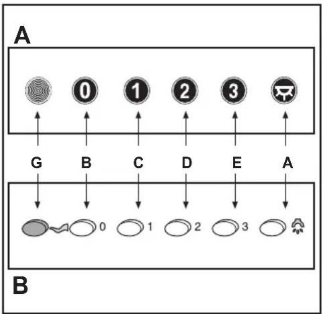
- COMMANDS:(Fig.21A)MECHANICAL\_(Fig.21B) Elliptic the key symbols are explained below:
$$ \begin{array}{l} \mathbf {A} = \text { LIGHT } \ \mathbf {B} = \text { O F F } \ \mathbf {C} = \text { SPEED } \mathbf {I} \ \mathbf {D} = \text { SPEED II } \ \mathbf {E} = \text { S P E E D } \quad \text { I I I } \ \mathbf {G} = \text { MOTOR WORKING indicator } \ \end{array} $$
THE MANUFACTURER DECLINES ALL RESPONSIBILITY FOR EVENTUAL DAMAGES CAUSED BY BREACHING THE ABOVE WARNINGS.
ALGEMEEN
INSTALLATIE INSTRUCTIES
C = knop TWEEDE SNELHEID
D = knop DERDE SNELHEID
E=knopTIMER AUTOMATISCHE ONDERBREKING na 15 minuten (*)
F = knop RESET ALARM VERZADIGDE FILTERS
C = knop EERSTE SNELHEID
D = knop TWEEDW DERDE SNELHEID
E = knop DERDE SNELHEID
F = knop TIMER AUTOMATISCHE ONDERBREKING na 15 minuten (*)
C = knop EERSTE SNELHEID
D = knop TWEEDW DERDE SNELHEID
E = knop DERDE SNELHEID
G = controlelampje WERKENDE MOTOR
DE FABRIKANT IS NIET AANSPRAKELIJK VOOR SCHADE DIE VOORTVLOEIT UIT HET NIET IN ACHT NEMEN VAN DE BOVENSTAANDE VOORSCHRIFTEN.
GENERALIDADES
Tecla A = acende/apaga as luzes
natural_image
Black-and-white map of Europe showing country borders (no text or labels)3LIK0215