BO550DNE - Cooker BOMPANI - Free user manual and instructions
Find the device manual for free BO550DNE BOMPANI in PDF.
Frequently Asked Questions - BO550DNE BOMPANI
User questions about BO550DNE BOMPANI
0 question about this device. Answer the ones you know or ask your own.
Ask a new question about this device
Download the instructions for your Cooker in PDF format for free! Find your manual BO550DNE - BOMPANI and take your electronic device back in hand. On this page are published all the documents necessary for the use of your device. BO550DNE by BOMPANI.
USER MANUAL BO550DNE BOMPANI
USO ACCESSORI DEL FORNO
∅ 145 1,0 kW - Plaque Normale
1,5 kW - Plaque Rapide
ø 180 1,5 kW - Plaque Normale
2,0 kW - Plaque Rapide
PUISSANCES DES ELEMENTS
ALLUMAGE DU BRÛLEUR DU FOUR
Technical data and specifications 19
Installation 20 - 21
Ventilation 20
Positioning 20
Fitting the feet 20
Gas connection 20
Adapting to different types of gas 20
Replacing the injectors 20
Regulating the air 20
Minimum setting 21
Electrical connection 21
Electric ignition 21
Safety device 21
For the user 22 - 25
Ventilation 22
Igniting the burners 22
Igniting the gas oven 22
Igniting the gas grill 22
Safety device 22
Electrical switch-on 22
Using the gas hob 22
Using the electric hot-plates 22
Using the gas oven 22
Using the gas or electric grill 22
Using the static electric oven 4 23
Using the static electric oven 4 "new" 23
Using the electric fan oven 4 23
Using the multifunction electric oven 4 .... 23
Using the multifunction electric oven 23
Using the rotisserie 23
Using the minute minder 23
Using the single-control cooking timer 24
Warming compartment 24
Removing the oven door 24
Using oven accessories 24
Advice and precautions 24
European Directive 2002/96/EC (WEEE) ...... 25
European Regulation 1935/2004 25
Figures 58 - 60
- Thank you for choosing one of our quality products, capable of giving you the very best service. To make full use of its performance features, read the parts of this manual which refer to your appliance carefully. The Manufacturer declines all responsibility for injury or damage caused by poor installation or improper use of the appliance.
- To ensure its appliances are always at the state of the art, and/or to allow constant improvement in quality, the manufacturer reserves the right to make modifications without notice, although without creating difficulties for users.
- When ordering spare parts, inform your dealer of the model number and serial number punched on your appliance's nameplate, visible inside the warming compartment or on the back of the cooker.
-
APPLIANCE COMPLYING WITH THE FOLLOWING DIRECTIVES:
-
EEC 2009/142/CE (ex 90/396)
- 2006/95/EC Low Voltage (replaces 73/23/EEC and subsequent amendments)
- EEC 2004/108 (radio-frequency interference)
- European Regulation 1935/2004 (materials in contact with food)
- European Regulation 1275/2008
- EEC 40/2002
- EEC 92/75
- 2002/96/EC (WEEE)
- 2005/32/CE (Energy-using Products)
FOREWORD
- Refer only to the headings and sections covering accessories actually installed on your cooker.
GB
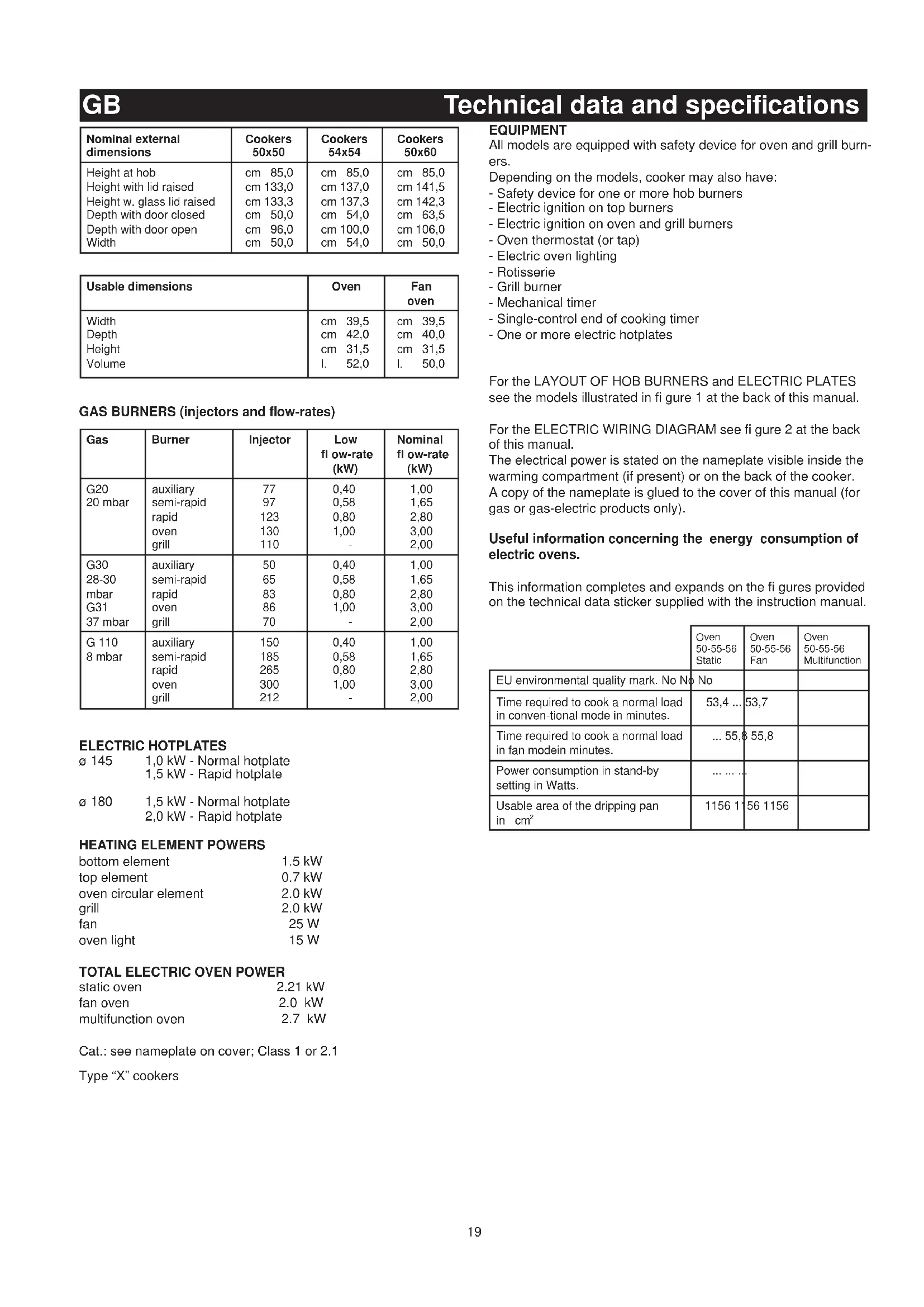
Technical data and specifications
| Nominal external dimensions | Cookers 50x50 | Cookers 54x54 | Cookers 50x60 |
| Height at hob | cm 85,0 | cm 85,0 | cm 85,0 |
| Height with lid raised | cm 133,0 | cm 137,0 | cm 141,5 |
| Height w. glass lid raised | cm 133,3 | cm 137,3 | cm 142,3 |
| Depth with door closed | cm 50,0 | cm 54,0 | cm 63,5 |
| Depth with door open | cm 96,0 | cm 100,0 | cm 106,0 |
| Width | cm 50,0 | cm 54,0 | cm 50,0 |
| Usable dimensions | Oven | Fan oven |
| Width | cm 39,5 | cm 39,5 |
| Depth | cm 42,0 | cm 40,0 |
| Height | cm 31,5 | cm 31,5 |
| Volume | l. 52,0 | l. 50,0 |
GAS BURNERS (injectors and flow-rates)
| Gas | Burner | Injector | Low fl ow-rate (kW) | Nominal fl ow-rate (kW) |
| G20 | auxiliary | 77 | 0,40 | 1,00 |
| 20 mbar | semi-rapid | 97 | 0,58 | 1,65 |
| rapid | 123 | 0,80 | 2,80 | |
| oven | 130 | 1,00 | 3,00 | |
| grill | 110 | - | 2,00 | |
| G30 | auxiliary | 50 | 0,40 | 1,00 |
| 28-30 | semi-rapid | 65 | 0,58 | 1,65 |
| mbar | rapid | 83 | 0,80 | 2,80 |
| G31 | oven | 86 | 1,00 | 3,00 |
| 37 mbar | grill | 70 | - | 2,00 |
| G 110 | auxiliary | 150 | 0,40 | 1,00 |
| 8 mbar | semi-rapid | 185 | 0,58 | 1,65 |
| rapid | 265 | 0,80 | 2,80 | |
| oven | 300 | 1,00 | 3,00 | |
| grill | 212 | - | 2,00 |
ELECTRIC HOTPLATES
∅ 145 1,0 kW - Normal hotplate
1,5 kW - Rapid hotplate
∅ 180 1,5 kW - Normal hotplate
2,0 kW - Rapid hotplate
HEATING ELEMENT POWERS
| bottom element | 1.5 kW |
| top element | 0.7 kW |
| oven circular element | 2.0 kW |
| grill | 2.0 kW |
| fan | 25 W |
| oven light | 15 W |
Cat.: see nameplate on cover; Class 1 or 2.1
Type "X" cookers
EQUIPMENT
All models are equipped with safety device for oven and grill burners.
Depending on the models, cooker may also have:
- Safety device for one or more hob burners
- Electric ignition on top burners
- Electric ignition on oven and grill burners
- Oven thermostat (or tap)
- Electric oven lighting
- Rotisserie
- Grill burner
- Mechanical timer
- Single-control end of cooking timer
- One or more electric hotplates
For the LAYOUT OF HOB BURNERS and ELECTRIC PLATES see the models illustrated in figure 1 at the back of this manual.
For the ELECTRIC WIRING DIAGRAM see figure 2 at the back of this manual.
The electrical power is stated on the nameplate visible inside the warming compartment (if present) or on the back of the cooker.
A copy of the nameplate is glued to the cover of this manual (for gas or gas-electric products only).
Useful information concerning the energy consumption of electric ovens.
This information completes and expands on the figures provided on the technical data sticker supplied with the instruction manual.
| Oven50-55-56Static | Oven50-55-56Fan | Oven50-55-56Multifunction | |
| EU environmental quality mark. No No | No | ||
| Time required to cook a normal load in conventional mode in minutes. | 53,4 ... | 53,7 | |
| Time required to cook a normal load in fan modein minutes. | ... 55,8 | 55,8 | |
| Power consumption in stand-by setting in Watts. | ... ... ... | ||
| Usable area of the dripping pan in cm^2 | 1156 1 | 56 1156 |
GB
Installation
INSTALLATION
The appliance must be installed by qualified staff working in accordance with the regulations in force.
Before installing, ensure that the appliance is correctly preset for the local distribution conditions (gas type and pressure).
The presettings of this appliance are indicated on the nameplate shown on the cover.
This appliance is not connected to a fl ue gas extractor device. It must be installed and connected in accordance with the regulations in force.
This appliance may only be installed and may only operate in rooms permanently ventilated in accordance with national regulations in force.
VENTILATION
The rooms in which gas appliances are installed must be well ventilated in order to allow correct gas combustion and ventilation.
The air flow necessary for combustion is at least 2 m^3/h for each kW of rated power.
POSITIONING
Remove the packaging accessories, including the films covering the chrome-plated and stainless steel parts, from the cooker.
Position the cooker in a dry, convenient and draft-free place. Keep at an appropriate distance from walls which may be damaged by heat (wood, linoleum, paper, etc.).
The cooker may be free-standing (class 1) or between two units (in class 2 st 2-1) the sides of which must withstand a temperature of 100^ C and which must not be higher than the working table, in the event of different installation arrangements with a side wall above the working table, the wall must be at least 20 cm from the top of the appliance.
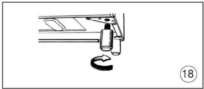
FITTING THE FEET (present only in a few models)
Cookers are equipped with adjustable feet to be screwed into their front and rear corners respectively. The feet allow the height of the appliance to be adjusted, in order to set it fl ush with the adjoining unit, to level it with other worktops and to ensure even distribution of the liquids in pans. See fi g. 18
CONNECTING TO THE GAS SUPPLY
Before connecting the cooker, check that it is preset for the gas to be used. Otherwise, make the conversion as described in the section headed "Adapting to different gas types". The connection is on the right; if the pipe has to pass behind the cooker, it must be kept low down where the temperature is about 50^ C.
- Rigid connection (see fig. 3 A + B)
The connection to the mains gas supply may be made using a rigid metal pipe or with a metal hose. Remove the hose connector (if already fi tted) and screw the rigid union onto the threaded connection of the gas train (see fi g. 3A). The union for rigid connection may already be fi tted on the gas train, or may be amongst the cooker accessories. Otherwise, it can be obtained from your dealer.
If national regulations permit, a metal hose complying with the national standards can be screwed directly onto the threaded connection of the gas train, fi tting a seal (see fi g. 3B). However, users are strongly recommended always to fi t the rigid union.
- Connection using a rubber hose (see fig. 3C). (For butane/propane gas only).
Connect a rubber hose carrying the conformity mark currently in force to the hose connector. The hose must be replaced at the date indicated at the latest, and must be secured at both ends using standard hose clamps. It must be absolutely accessible to allow its condition to be checked along its entire length.
CAUTION:
- Use of the hose connector is only permitted for free-standing installation. If the appliance is installed between two class 2 st. 2-1 unions, the rigid union is the only form of connection permitted.
IMPORTANT:
- After installation, check that the connections are airtight.
- For operation with butane/propane, check that the gas pressure is as indicated on the nameplate.
- Use only standard rubber hoses. For LPG, use a hose which complies with the national regulations in force.
- Avoid sharp bends in the pipe and keep it well way from hot surfaces.
References to the regulations covering the gas connection to the appliance: ISO 7-1.
ADAPTING TO DIFFERENT TYPES OF GAS
- Remove the grid, the burner caps (A), and the burners (B);
- Unscrew and remove the injector in the bottom of each injector holder (C);
- replace the injector in accordance with the table in page 19 using a 7 mm socket wrench, tighten and screw right down;
- check that the system is gas-tight;
- replace the burners, the burner caps and the grid.
IMPORTANT:
- Never over-tighten the injectors;
- after replacing, check that all the injectors are airtight.
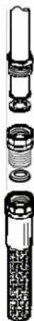
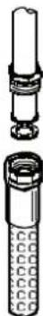
REPLACING THE HOB BURNER INJECTORS (Fig. 4)
- Remove the lid of the cooker by lifting it off its supports;
- remove the grids, burner caps and burners, lifting them off;
- unscrew the 2 screws (above) or nuts (below) at the back which secure the work top, and pull it out forward.
- remove the mixer pipes and replace the injectors using a 7 mm socket wrench.
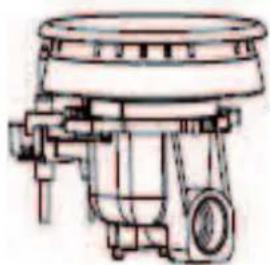
REPLACING THE OVEN BURNER INJECTOR (Fig. 5)
- Loosen the screw which secures the bottom of the oven;
- remove the oven bottom (pulling it forward);
- remove the oven burner, after taking out the screw which secures it;
- replace the injector using a 7 mm socket wrench.
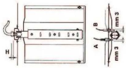
REPLACING THE GRILL BURNER INJECTOR (Fig. 6)
- Remove the burner after taking out the two screws which secure it;
- replace the injector using a 7 mm socket wrench.
IMPORTANT:
- Never over-tighten the injectors;
- after replacing, check that all the injectors are airtight.
REGULATING THE BURNER AIR
Refer to the table below (indicative values) for regulation of the gap H in mm (fi g. 6 for the grill).
| Burner | G20 20mbarG25 25mbar | G30 28-30mbarG31 37mbar |
| Oven | - | - |
| Grlll | 4 | 8 |
Check operation of the burner:
Ignite the burner at maximum flame;
- the tongue of the fl ame must be clear and with no yellow tip, and must adhere closely to the burner. If too much air is supplied, the fl ame detaches from the burner and may be dangerous. If the air supply is insufficient, the fl ame has a yellow tip and soot may form.
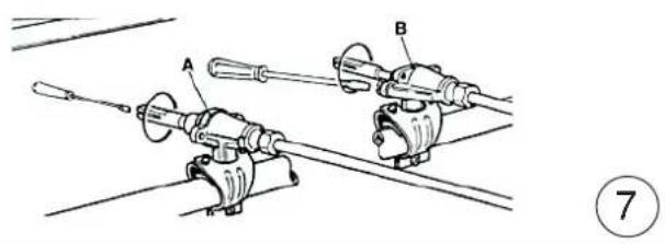
SETTING HOB BURNER MINIMUM LEVELS
If the cooker is to work on bottled gas (butane/propane), the tap by-pass must be screwed right down. The cooker may be equipped with type A taps, with by-pass inside (accessed by inserting a small screwdriver into the rod) or type B
GB
Installation
taps, with by-pass on the outside on the right (accessed directly). See figure 7.
If the cooker is to work on natural gas, proceed as follows for both types of tap:
- Ignite the burner at maximum flame;
- pull off the knob, without using a lever against the control panel, which might be damaged;
- access the by-pass with a small screwdriver and back off by about 3 turns (turning the screwdriver anti-clockwise);
- turn the tap rod anti-clockwise again until it stops: the burner will be at maximum flame;
- screw the by-pass slowly back in, without pushing the screw-driver, until the flame has apparently shrunk to 1/4 of the maximum size, checking that it is sufficiently stable even in quite strong draughts.
SETTING OVEN BURNER MINIMUM LEVELS
If the cooker is to work on bottled gas (butane/propane), the thermostat by-pass must be screwed right down.
If the cooker is to work on natural gas, proceed as follows:
- Remove the oven bottom (loosen the screw to remove the bottom);
- ignite the oven burner, turning the knob pointer to the maximum setting;
- shut the oven door;
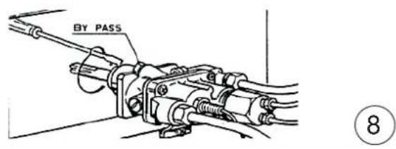
- access the thermostat or tap by-pass (see fi g. 8);
- back off the thermostat by-pass by about 3 turns;
- after 5 or 6 minutes, turn the knob pointer to the minimum setting;
- slowly re-tighten the by-pass, watching the fl ame decrease in size through the window in the closed oven door until the tongue of the fl ame is about 4 mm long. Never keep the fl ame too low. It must be stable even when the oven door is opened or closed quickly;
- turn off the burner and replace the oven bottom.
CONNECTING TO THE ELECTRICAL MAINS
Before making the connection, check that:
- the mains voltage is as indicated on the nameplate;
- the earth connection is in good working order.
For direct connection to a power mains, a device that ensures disconnection from the mains must be installed, with a opening distance for the contacts that allows for a complete disconnection under conditions of category III electrical overload, in conformity with the installation instructions.
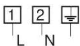
If the appliance power lead is not fitted with a plug, use an approved standard type, remembering that: - the green-yellow wire must be used for the earth connection;
- the blue wire is the neutral;
- the brown wire is live;
- the lead must never touch hot surfaces over about 75 degrees C;
- replacement leads must be of type H05RR-F or H05V2V2-F of suitable size (see diagrams in fig. 2).
- if the appliance is supplied without lead, using type H05RR-F or H05V2V2-F cable of suitable size (see diagrams in fi g. 2).
IMPORTANT: the manufacturer declines all liability for damage due to failure to comply with the regulations and standards in force.
Check that the appliance is correctly connected to the earth (see diagrams in fig. 2 at the back of the manual).
FOR COOKERS WITH ELECTRIC IGNITION
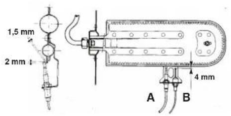
The correct gaps between the electrode and the burner are shown in figures 5 and 6.
If no spark is generated, do not keep on trying as this might damage the generator.
Possible causes of malfunctions:
- spark plug damp, dirty or broken;
- electrode-burner gap not correct;
- spark plug wire broken or without sheathing;
- spark discharging to earth (to other parts of the cooker);
-
generator or microswitch damaged;
-
air has built up in the pipes (particularly if the cooker has been out of use for a long time);
- air-gas mixture incorrect (poor fuel setting).
THE SAFETY DEVICE
The correct gap between the end of the thermocouple sensor and the burner is shown in figures 5 and 6.
To check that the valve is working properly, proceed as follows:
- ignite the burner and leave it to work for about 3 minutes;
- turn off the burner by returning the knob to off position (●);
- after 90 seconds for hob burners, 60 seconds for oven and grill burners, turn the knob pointer to the "on" position;
- release the knob in this position and move a burning match towards the burner; IT MUST NOT IGNITE.
Time needed to excite the magnet during ignition: 10 seconds approx.
Automatic tripping time, after fl ame has been turned off: not more than 90 seconds for hob burners; not more than 60 seconds for oven and grill burners.
IMPORTANT:
- Before doing any work inside the cooker, disconnect the mains plug and shut the gas tap.
- Never use matches to check the gas circuit for leaks. If a specific control device is not available, foam or very soapy water can be used.
- When re-closing the hob, check that the electrical wires of the spark plugs (if present) are not close to the injectors, so that they cannot run across them.
GB
For the user
HOW TO USE THE COOKER
VENTILATION
All gas cooking appliances produce heat and moisture in the rooms where they are installed. Take care to ensure that the kitchen is well ventilated; keep the ventilation openings unobstructed or install an extractor hood with fan.
In case of intensive or prolonged use, additional ventilation may be required; open a window, or increase the extractor fan power.
IGNITING THE HOB BURNERS

- Press the knob and turn it anti-clockwise until it reaches the symbol on the control panel (maximum flame position);
- at the same time, move a burning match towards the burner head;
- to reduce the fl ame, turn the knob further in the same direction until its pointer is against the 🔔 symbol (minimum fl ame position).
FOR HOB BURNERS EQUIPPED WITH SAFETY DEVICE

- Press the knob and turn it anti-clockwise until it reaches the symbol on the control panel (maximum flame position);
- move a burning match towards the burner, keeping the knob pressed right dow for about 10 seconds;
- then release the knob and check that the burner remains on. Otherwise, repeat the operation.
IGNITING THE OVEN BURNER
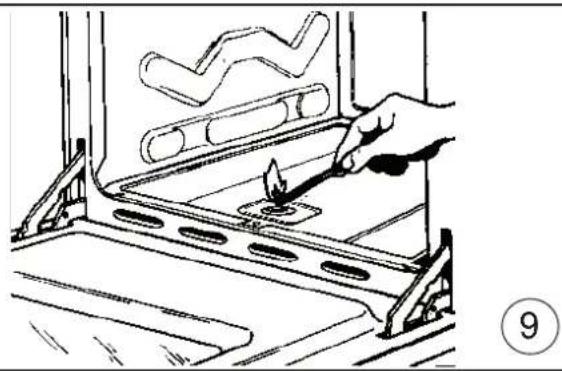
- Open the oven door;
- press the knob and turn it anti-clockwise to the maximum flame position;
- move a burning match towards the hole in the centre of the oven bottom and press the knob right down (see fi g. 9);
- check that the burner has ignited, looking through the hole in the centre of the bottom, keeping the knob pressed all the time;
- after about 10 seconds, release the knob and check that the burner remains on. Otherwise, repeat the operation.
IGNITING THE GRILL BURNER (GAS GRILLS)
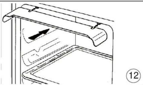
- Fit the control knob guard as shown in fig. 12;
- press the oven knob and turn it to the right until it reaches the stop;
- move a burning match towards the perforated burner pipe and press the knob right down (see fig. 10);
- check that the burner has ignited, keeping the knob pressed down;
- after about 10 seconds, release the knob and check that the burner remains on. Otherwise, repeat the operation.
SAFETY DEVICE
Burners equipped with this device have the advantage that they are protected if they accidentally go out. If this occurs, the supply of gas to the burner concerned is automatically cut off, preventing the hazards deriving from a leak of unburnt gas. The gas supply must be cut off within no more than 60 seconds for the oven and grill burners or 90 seconds for the hob burners.
FOR COOKERS WITH ELECTRIC IGNITION
All the above applies, except that the match is no longer required; a spark is obtained by pressing the button on the control panel once or more, or by pressing the knob of the burner to be ignited. If electronic ignition is difficult with some types of gas, set the knob on the low (small flame) setting.
- For cookers with electric ignition of the oven and grill burners, ensure the oven door is completely open when these burners are ignited;
- Do not operate the ignition device for more than 10 seconds when igniting the oven and grill burners. If the burner has not lit after these 10 seconds, stop using the device, leave the door open and wait one minute before trying again to ignite the burner. If the
ignition device malfunctions again, light the burner with a match and call the after-sales service.
IMPORTANT:
- Diffi culty in igniting burners is normal if the cooker has been out of use for some time. The air accumulated in the pipes will be expelled in a few seconds;
- Never allow too much unburnt gas to flow from the burners. If ignition is not achieved within a relatively short time, repeat the procedure after returning the knob to the off position (●;
- when the oven and grill are lit for the first time, a smell may be noticed and smoke may come out of the oven. This is because of the surface treatment and oily residues on the burners.
HOW TO USE THE HOB BURNERS
Use pans of diameter suitable for the burner type. The flames must not project beyond the base of the pan. Recommended sizes:
- for auxiliary burners = pans of at least 8 cm
- for semi-rapid burners = pans of at least 14 cm
- for rapid burners = pans of at least 22 cm.
N.B.: Never keep the knob at settings between the maximum flame
symbol and the off position ( )
FOR COOKERS EQUIPPED WITH ELECTRIC HOTPLATES
The different heat settings are obtained as follows:
- 1 = minimum setting for all hotplates;
- 6 = maximum setting for normal and rapid hotplates (with red disc);
- 0 = off.
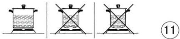
Pans must never be smaller in diameter than the hotplates and their bottoms must be as fl at as possible (see fi g. 11).
IMPORTANT:
- Never leave hotplates on without pans, except when first used; leave for about 10 minutes to dry oil or moisture residues;
- if the hotplate is to be out of use for a long time, apply a little grease to its painted surface;
- do not allow spills to burn onto the hotplate, requiring the use of abrasive cleaners.
- After igniting the burner, leave the oven to heat up for about 10 minutes;
- place the food for cooking in an ordinary oven dish and place it on the chrome-plated shelf;
- place the food in the oven, using the shelf on the third pair of runners whenever possible, and turn the knob pointer to the desired setting;
- cooking can be observed through the window in the door with the oven light on. This will avoid opening and closing the door frequently, unless oil or fat has to be added to the dish.
N.B.: For cookers without thermostat:
- with the knob on the maximum setting = 270 degrees C
- with the knob on the minimum setting ♦ = 150 degrees C
- All other temperatures between 150 and 270 degrees C are obtained approximately by positioning the knob between the maximum and minimum settings.
Never leave the knob in positions between the maximum symbol
and the off setting (●).
- fit the knob guard (see fig. 12);
- light the burner and wait a few minutes to give the burner time to warm up;
- place the foods on the chrome-plated shelf;
- insert on the highest runner;
- insert the drip tray on the bottom runner;
- gently close the oven door, resting it against the knob guard;
- after a few minutes, turn the food to expose the other side to the infrared radiation (the cooking time depends on the type of food and personal taste).
GB
For the user
The table below "Food to be grilled" will serve as a guide.
N.B.: the first time the grill is used smoke will come out of the oven. Before inserting foods for cooking, wait until any oil residues on the burner have completely burnt away. The grill must only be used at its full rated heat.
IMPORTANT: accessible parts may be hot when the grill is in use! Keep children well away.
- ignite the grill heating element;
- place the foods on the chrome-plated shelf;
- insert on the highest runner;
- insert the drip tray on the bottom runner;
- gently close the oven door;
- after a few minutes, turn the food to expose the other side to the infrared radiation (the cooking time depends on the type of food and personal taste). To see table "Food to be grilled"
The grill element in the top of the oven is switched on by turning the thermostat knob clockwise to the grill symbol on the control panel. The red light will come on to show the element is in operation.
STATIC ELECTRIC OVEN 4
With different heating elements controlled using a selector switch and regulated by a thermostat, starting from the 0 (off) position, as the knob is turned clockwise the settings available are:
- symbol ⚙:the oven light is switched on (it will always remain on even when the knob pointer is turned to the other settings).
- symbol ☑: grill (in top of oven) is switched on.
- symbol 📊: roaster switches on with grill on.
- symbol ☐: oven top and bottom elements switch on (conventional cooking function).
N.B. - The yellow light switches on and off as the thermostat is tripped. Before placing food for cooking inside, allow the oven to heat up for at least 10 minutes.
STATIC ELECTRIC OVEN "4 New "
With different heating elements controlled using a selector switch and regulated by a thermostat, starting from the 0 (off) position, the knob can be turned clockwise to the following settings:
- symbol ☑: oven lamp on (it will remain on even if the knob pointer is turned to the other settings).
- symbol Ⓞ:slow cooking using the bottom element; the oven temperature is regulated using the thermostat knob.
- symbol Ⓞ:conventional "static" oven cooking, the oven temperature is controlled using the thermostat knob.
- symbol ☐:grill on.
N.B. - The yellow light switches on and off as the thermostat is tripped. Before placing food inside, allow the oven to heat up for at least 10 minutes.
ELECTRIC FAN OVEN WITH 4 COOKING PROGRAMS
With different heating elements controlled using a selector switch and regulated by a thermostat, starting from the 0 (off) position, the knob can be turned clockwise to the following settings:
- symbol seven lamp on (it will remain on even if the knob pointer is turned to the other settings).
- symbol operation of fan.
- symbol cooking with fan oven, on one or two levels, the oven temperature is controlled using the thermostat knob.
- symbol ⚡: grill on.
N.B. - The yellow light switches on and off as the thermostat is tripped.
Before placing food for cooking inside, allow the oven to heat up for at least 10 minutes.
MULTIFUNCTIONS ELECTRIC OVEN 4 POSITIONS
With different heating elements controlled using a selector switch and regulated by a thermostat, starting from the 0 (off) position, the knob can be turned clockwise to the following settings:
- symboloven lamp on (it will remain on even if the knob pointer is turned to the other settings).
- symbol :conventional "static" oven cooking, the oven temperature is controlled using the thermostat knob.
- symbol ☒: cooking with fan oven, on one or two levels, the oven temperature is controlled using the thermostat knob.
- symbol : grill on;
N.B. - The yellow light switches on and off as the thermostat is tripped. Before placing food inside, allow the oven to heat up for at least 10 minutes.
MULTI-FUNCTION ELECTRIC OVEN
With different heating elements controlled using a selector switch and regulated by a thermostat, this oven offers various cooking methods.
There are three principle sources of heat:
a) Forced heat diffusion (fan oven).
b) Spontaneous heat diffusion (static oven).
c) Infra-red rays (grill).
Starting from the 0 (off) position and turning the selector knob clockwise, the following settings are obtained:
- symbol ☐: oven light and red warning light on, operation of fan.
- symbol □: conventional "static" oven cooking, the oven temperature is controlled using the thermostat knob.
- symbol ☐: cooking with fan oven, on one or two levels, the oven temperature is controlled using the thermostat knob.
- symbol ☐: on (on oven top element), the thermostat knob must be set at the maximum temperature.
- symbol 📋:infra-red cooking with fast grill, advised for long grilling: the thermostat knob must be set at the maximum temperature.
- symbol 📋: quick cooking using the fan oven, the oven temperature is controlled using the thermostat knob.
- symbol 🧑:slow cooking using fan oven, the oven temperature is controlled using the thermostat knob.
In all positions except zero (0) the red warning light and the oven light are on.
NOTE: The yellow warning light comes on according to thermostat variations. Before putting food in to be cooked, the oven should be pre-heated for at least 10 minutes.
HOW TO USE THE ELECTRIC GRILL WITH ELECTRIC OVEN
- For models with “Electric Oven” only, controlled by two knobs separately (selector-thermostat), grilling is permitted with the door closed, without using the front side. Temperatures above 200°C. must not be used when grilling with the door closed.
HOW TO USE THE ROTISSERIE
a) Grilling with the door open.
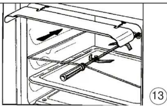
- fi t the control knob guard as shown in fi gure 13.
- ignite the grill burner, or switch on the grill element;
- impale the meat for cooking on the spit and fix it in the centre of the two forks;
- insert the end of the spit into the motor drive socket;
- remove the handle from the spit;
GB
For the user
- place the drip tray on the bottom runner of the oven;
- gently close the oven door, resting it against the knob guard;
- start the rotisserie motor by pressing the switch on the symbol.
- baste the meat from time to time. When cooked, screw the handle onto the spit and remove from the motor drive socket.
b) Grilling with the door closed.
- as above without using the knob protection as shown in fig.13
CAUTION: The spit forks may have sharp points. Handle with care.
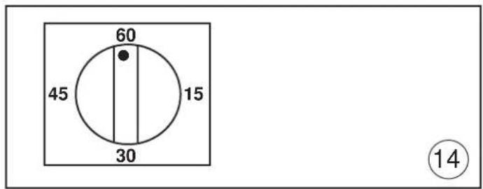
HOW TO USE THE MINUTE MINDER (Fig. 14)
Set the cooking time considered necessary by turning the timer knob clockwise. An alarm will sound at the end of the preset time.
USE OF SINGLE-CONTROL END OF COOKING TIMER (WITHOUT CLOCK) (Fig. 15)
This allows the cooking time to be programmed.
Operation:
- Move the knob to the desired cooking time (120 mins max. for the electric oven; 100 mins max. for the gas oven).
- Choose the temperature using the thermostat knob and move the selector knob to the required cooking method.
- When the programming knob is at the 0 position the oven will switch itself off. This is automatic.
- Move the thermostat knob back to symbol ●
- Move the selector knob to symbol 0.
N.B. If the timer is not used, the oven programming knob is to be set to the manual position 🏠
WARMING COMPARTMENT
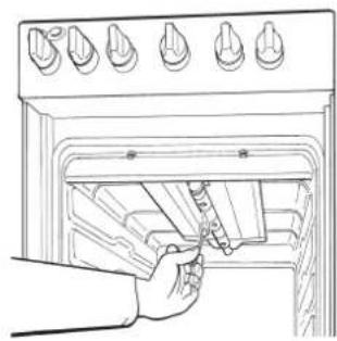
To open the warming compartment, open the flap door with one hand (see figure 16).
To close the warming compartment, simply press the fl ap door back into place.
REMOVING THE OVEN DOOR
The door can be removed to clean the oven in an easier way following this instructions:
1) Open the door completely.
2) Turn the two levers "B" bringing them from position 1 to position 2 (see fig.17).
3) Close the door slowly to a stop, grab it with both hands from side to side, close it further and pull it by lifting it upwards.
4) To replace the door you must follow the procedure in reverse order, insert the two hinges in their seats and open the door completely.
5) Turn the two levers "B" bringing them back in position 1.
6) Close the door normally.
HOW TO USE OVEN ACCESSORIES
- The oven shelf is designed to take normal oven dishes for cooking sweets or roasts, or is used without a pan for cooking foods under the grill.
- The drip pan under the grill is used to collect juices, which drip from the food that is cooked directly on the grill. The drip pan can also be used for cooking
- Remember that cooking times may vary if food is cooked on two shelves at the same time.
GENERAL PRECAUTIONS
- This appliance must not be used by those with reduced mental or motor capacities (including children), or by those who are not experienced or know how to work it, unless supervised or instructed on its use by safety personnel.
Children must be supervised to ensure that they do not play with the appliance.
- Always disconnect the power supply before any work inside the oven or where live parts may be accessed.
- Never use the warming compartment for storing infl ammable liquids or items which do not withstand heat, such as wood, paper, aerosol cans, matches, etc.
- Make frequent checks on the rubber connection hose, ensuring that it is well away from hot surfaces, that there are no sharp bends or kinks, and that it is in good condition. The hose must be replaced at the latest at the indicated date and must be secured at both ends using a standard hose clamp.
- If taps become stiff to operate over time, contact the After-Sales service.
- Wash enamelled or chrome-plated parts with soapy lukewarm water or non-abrasive detergents. A metal brush may be used to remove deposits from hob burners and fl ame caps. Dry thoroughly.
- Never use abrasives to clean enamelled or chrome-plated parts.
- Do not use too much water when washing the hob. Take care that no water or other substances enter the burner housing holes, as this may be dangerous.
- The spark plugs for electric ignition must be kept clean and dry; always check after use, particularly if there have been drips or overflows from pans.
- Never close glass lids until the hob burners or hotplates have cooled completely; it might shatter or crack.
- Never knock enamelled parts or ignition spark plugs (where present).
- The main or wall gas tap should be turned off when the cooker is not in use.
- Never move the cooker by means of the handle.
- Do not clean the glass doors of the oven with rough, abrasive materials or sharp metal scrapers, since they may scratch the surface and cause the glass to shatter.
- Do not use vapor jets to clean the appliance.
- The cooker does not have an installation stand.
CAUTION: The use of a gas cooking appliance results in the production of heat, moisture and products of combustion in the room in which it is installed. Ensure that the kitchen is well ventilated especially when the appliance is in use: keep natural ventilation holes open or install a mechanical ventilation device (mechanical extractor hood).
CAUTION: This appliance is for cooking purposes only. It must not be used for other purposes, for example room heating.
No liability is accepted for injury or damage caused by poor installation or improper use of the cooker.
In case of malfunctions, particularly gas leaks or short-circuits, contact your engineer without delay.
EUROPEAN DIRECTIVE 2002/96/EC (WEEE): INFORMATION FOR THE CONSUMER

Fig. A
This information is strictly addressed to those who have a product showing the symbol below (Fig.A). This symbol is indicated on the technical data sticker (rating label) placed on the product itself. This symbol indicates that the appliance is considered as Waste Electrical and Electronic Equipment and complies with the European directive 2002/96/EC (WEEE).
Therefore this product is not to be treated as household waste. Instead it shall be handed over to the applicable collection point for the recycling of electrical and electronic equipment or it can be handed back to the retailer when you want to purchase a new equivalent product.
The consumer is responsible for a correct disposal of the product towards an appropriate collection point.
Otherwise the consumer can be exposed to a penalty sanction by laws in force for waste disposal.
Appropriate separate waste collection followed by recycling the product, the treatment and compatible environmental disposal contributes to avoid negative effects towards the environment and health and helps to recycle material which the product is composed of.
For more detailed information regarding the available waste collection systems of this product please contact your local city office or contact the retailer where the product was purchased.
The manufacturers and importers will obey to their responsibility for recycling, treatment and compatible environmental disposal by participating directly and through a joint cooperative system.
EUROPEAN REGULATION NO 1935/2004 – MATERIALS IN CONTACT WITH FOOD. NOTICE TO USERS.

The symbol shown here, which appears on the packaging, indicates that the materials in this product which may come into contact with food are compliant with the requirements of European Regulation No 1935/2004.
Inside the oven chamber, food might come into contact with oven shelves, dripping pans, pastry trays, oven door glazing, rubber gaskets, rotisserie spits, and the sides of the oven itself.
On the hob, contact is possible with pan stands, burners and the hob skin.
In the food-warmer, contact may occur with the sides of the compartment.
Директива 2002/96/EC (WEEE)......26
Directiva 2002/96/EC (RAEE) ......41
Regulamento Europeu n° 1935/2004 .....41
Figuras 58 - 60
Introdução
ANAMMA TOY KAYSTHPA ΦΟΥΡΝΟΥ
text_image
SR SR A R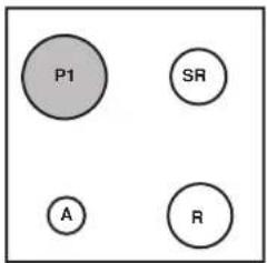
text_image
P1 SR A R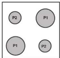
text_image
P2 P1 P1 P2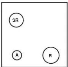
text_image
SR A RA = AUSILIARIO
=AUXILIAIRE
=AUXILIARY
= MAJAS
= AUXILIAR
= βοηθητικός
=AUXILIAR
SR = SEMIRAPIDO
= SEMI-RAPID
= SEMI-RAPID
= CPF/1H9A
= SEMI-RÁPIDO
= ημιταχύς
= SEMIRRÁPIDO
R = RAPIDO
= RAPIDE
= RAPID
= болыная
= RÁPIDO
= ταχύς
= RÁPIDO
P1 = PIASTRA ∅ 180
= PLAQUE ∅ 180
= HOTPLATE ∅ 180
=ЭЛКТРОКОПФОРКА 0 180
= DISCO ∅ 180
= εστια ∅ 180
= PLACA ∅ 180
P2 = PIASTRA ∅ 145
= PLAQUE ∅ 145
= HOTPLATE ∅ 145
= ЭЛКТРОКОПФОРКА 0 145
= DISCO ∅ 145
= εστία ο 145
= PLACA ∅ 145
1
A
B
C
D
3
text_image
1 2 3 4 5 L L L NSez. cavo
Section câble
Wire gauge
Сечение кабеля
Sec. cabo
Διατ. καλώδιου
Sección cable:
5x2.5 mm²
230 V BIFASE / BIPHASE / TWO-PHASE / ДВУХФАЗНЫЙ / BIFÁSICO / ΔΙΦΑΣΙΚΟ / BIFASICO
3.5 kW
2.2 - 3.5 kW
0 - 2.2 kW
3x2.5 mm²
3×1.5 mm²
3x 1 mm²
Sez. cavo
Section câble
Wire gauge
Сечение кабеля
Sec. cabo
Διατ. καλώδιου
Sección cable:
2
natural_image
Technical line drawing of a mechanical device with no visible text or symbolsA
B
C
4
Figure/Figures/Figures/Рисунки/Figuras/Eικόνες/Figuras
text_image
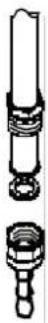
1,5 mm 2 mm 4 mm A BA =TERMOCOPPIA / THERMOCOUPLE / THERMOCOUPLE
TEPMOIIAPA/TERMOPAR/θΕΡΜΟΣΤΟΙΧΕΙΟΥ/ TERMOPAR
B = CANDELA D'ACCENSIONE / BOUGIE D'ALLUMAGE / SPARK PLUG / СВЕЧА ЗАЖИГАНИЯ / VELA DE IGNICÃO / МПОYZI ANAФЛЕЭНç / BUJÍA DE ENCENDIDO
5
text_image
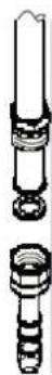
H mm 3 A BA =TERMOCOPPIA / THERMOCOUPLE / THERMOCOUPLE
ITPMOUPA/TERMOPAR/θEPMOΣTOIXEIOY/TERMOPAR
B =CANDELA D'ACCENSIONE / BOUGIE D'ALLUMAGE / SPARK PLUG / СВЕЧА ЗАЖИГАНИЯ / VELA DE IGNICÃO / МПОУЗІ ANAФЛЕЭНç / BUJÍA DE ENCENDIDO
6
natural_image
Technical line drawing of two mechanical components labeled A and B, connected by rods (no text or symbols beyond labels)7
text_image
BY PASS ⑧8
natural_image
Line drawing of a hand using a tool to test flame inside a heated chamber (no text or symbols)⑨
natural_image
Line drawing of a hand inserting a tool into an oven with six kitchen handles (no text or symbols)10
text_image
Diagram showing four different heating setups with different liquid levels and cross-sectional views, labeled with number 11.11
natural_image
Technical line drawing of a mechanical component with an arrow indicating direction (no text or symbols)12
natural_image
Technical line drawing of a mechanical assembly with clamps and a handle, no visible text or symbols13
Figure/Figures/Figures/Рисунки/Figuras/Eικόνες/Figuras
text_image
60 45 15 30 14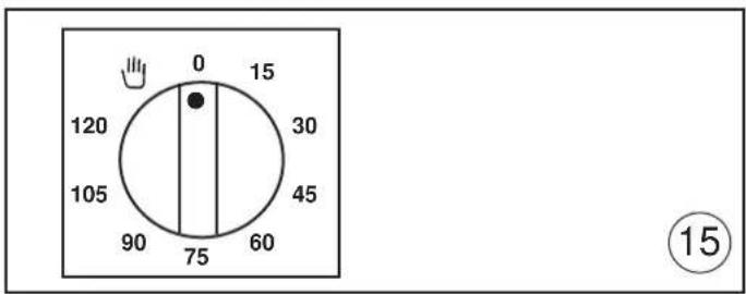
text_image
0 15 120 30 105 45 90 75 60 ⑮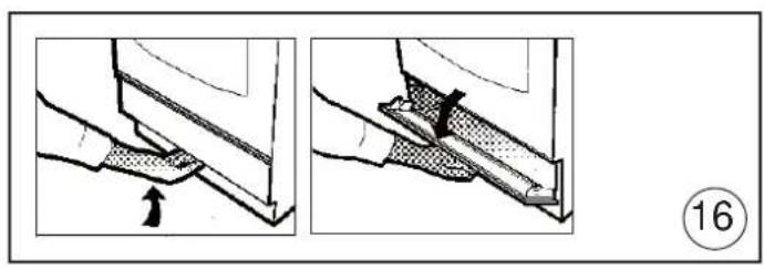
natural_image
Two-step diagram showing a hand holding a piece of material, with an arrow indicating direction and a numbered circle (16) in the corner.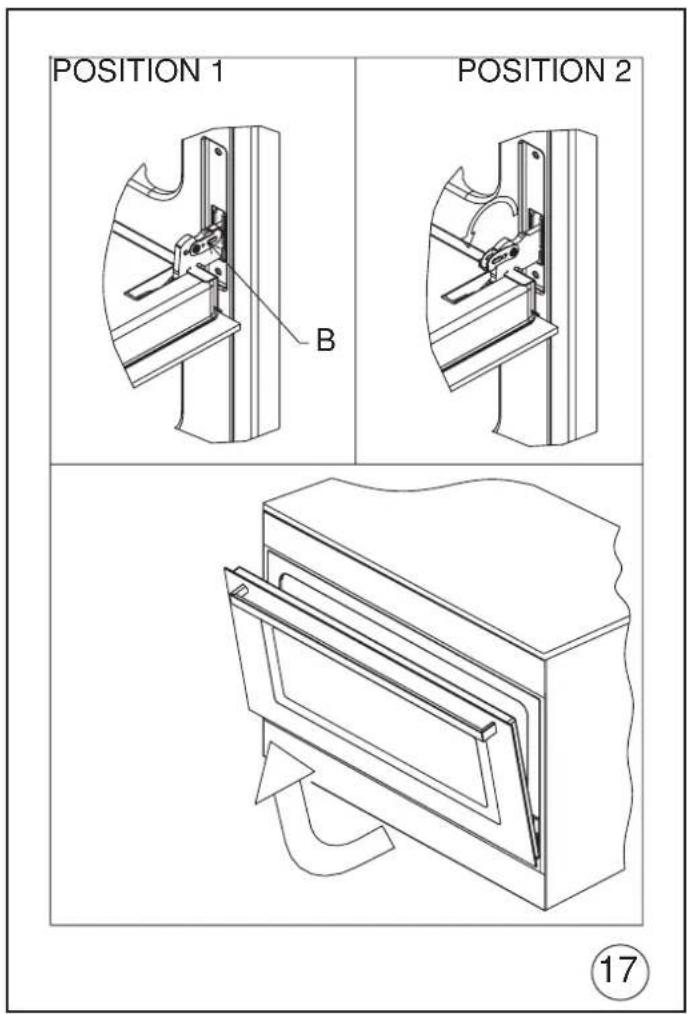
text_image
POSITION 1 POSITION 2 B ⑰