
AS 5324 X01 - Cooker SILVERLINE - Free user manual and instructions
Find the device manual for free AS 5324 X01 SILVERLINE in PDF.
| Product type | Built-in gas and electric hob |
| Brand | Silverline |
| Model | AS 5324 X01 |
| Dimensions (W x D) | 860 x 510 mm |
| Weight | Approximately 12 kg (estimated) |
| Number of gas burners | 4 |
| Gas burner types | Auxiliary (1 kW), Semi-rapid (1.75 kW), Rapid (3 kW), Wok (3.8 kW) |
| Number of electric plates | 2 |
| Power of electric plates | 2 x 1500 W |
| Total gas power | 10.5 kW |
| Gas consumption G20 (20 mbar) | 715 l/h |
| Gas consumption G30 (30 mbar) | 545 g/h |
| Gas category | II2H3+ |
| Electrical supply | 220-240 V ~ 50-60 Hz |
| Ignition | Automatic electronic |
| Safety device | Optional (FFD - automatic gas shut-off) |
| Pan support grids | Enamelled, dishwasher safe |
| Cleaning | Use soapy water and mild detergent; do not use steam cleaner |
| Installation | Built-in, with sealing gasket supplied |
| Gas conversion | Possible by an approved technician (injector change) |
| Installation class | 3 |
| Manual available | Yes, 183 pages in PDF |
Frequently Asked Questions - AS 5324 X01 SILVERLINE
User questions about AS 5324 X01 SILVERLINE
0 question about this device. Answer the ones you know or ask your own.
Ask a new question about this device
Download the instructions for your Cooker in PDF format for free! Find your manual AS 5324 X01 - SILVERLINE and take your electronic device back in hand. On this page are published all the documents necessary for the use of your device. AS 5324 X01 by SILVERLINE.
USER MANUAL AS 5324 X01 SILVERLINE
natural_image
Simple geometric symbol with a circle and two cross marks inside a rounded square (no text or labels)TR Ocak Kullanım Kılavuzu EN Built-in Hob User Manual AR دليل استخدام المو FR Utilisateur Cuisinière Manuel
SILVERLINE®
DEĞERLİ MÜŞTERİMİZ,
natural_image
Symbol of a trash bin with crossed lines and a blank rectangular base (no text or labels)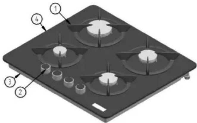
natural_image
Pure electrical circuit lines without any symbolsAS 5214
natural_image
Pure electrical circuit lines without any symbolsAS 5215
natural_image
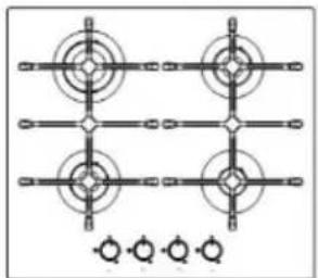
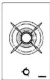
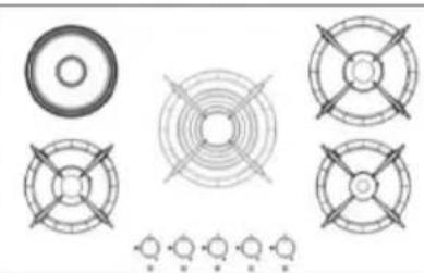
Grid pattern with concentric circles and a central circular target, no text or symbols presentAS 5216
natural_image
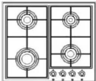
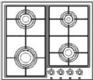
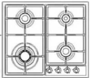
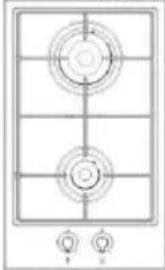
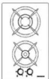
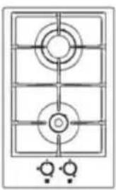
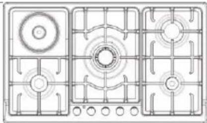
Line drawing of a two-gas stove with four circular vented outlets and a control panel at the bottom (no text or symbols)AS 5233
natural_image
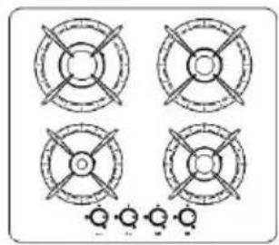
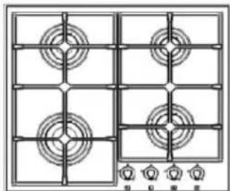
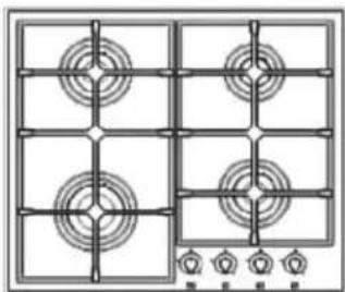
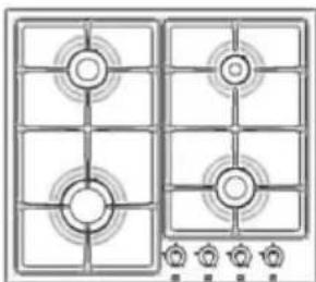
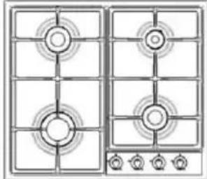
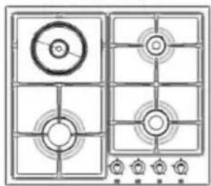
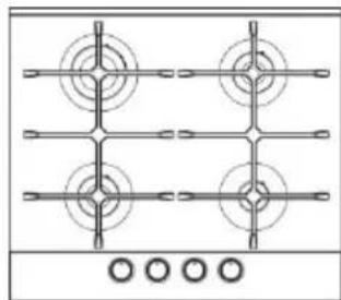
Diagram of a four-panel electric stove with circular vented outlets and control knobs at the bottom (no text or labels)AS 5238
natural_image
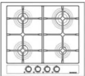
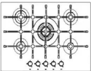
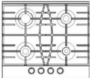
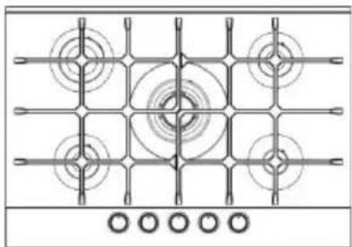
Diagram of a 3x4 grid layout with circular patterns and control buttons at the bottom (no text or symbols)AS 5239
natural_image
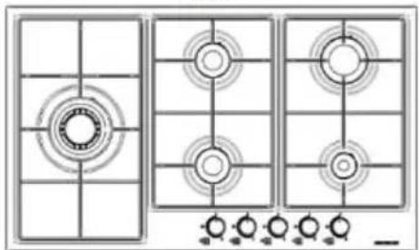
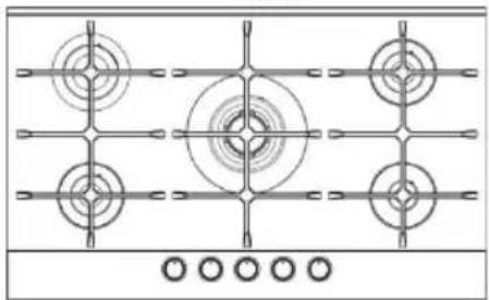
Technical diagram of a three-panel kitchen or dining area with circular fixtures and grid patterns (no text or symbols)AS 5271
natural_image
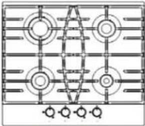
Grid of circular and rectangular patterns with directional arrows, no text or symbols presentAS 5240
natural_image
Four circular mechanical components with cross-shaped arms, arranged in a 2x2 grid (no text or symbols)CS 5217-CS 5217 W
natural_image
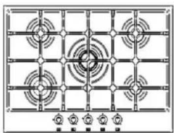
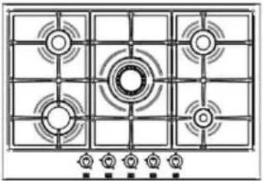
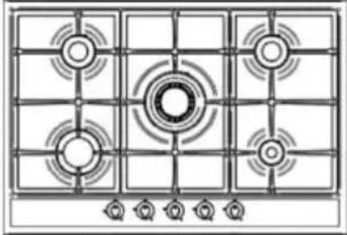
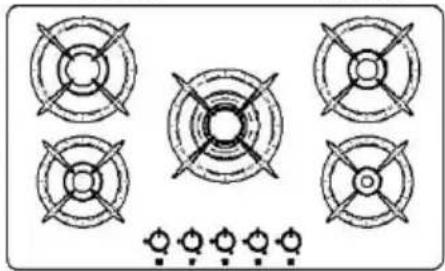
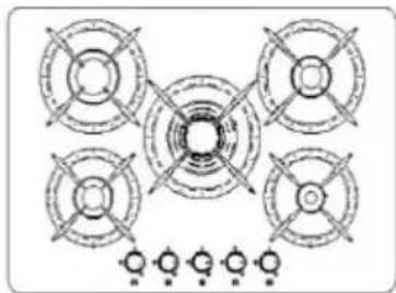
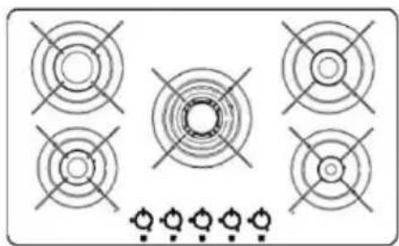
Top-down schematic of a gas stove with six circular vented lights arranged in a grid (no text or labels)AS 5241
natural_image
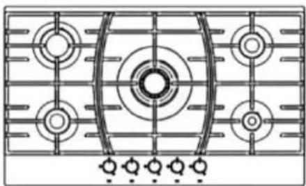
Grid pattern with concentric circles and rectangular blocks, no text or symbols presentAS 5242
natural_image
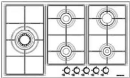
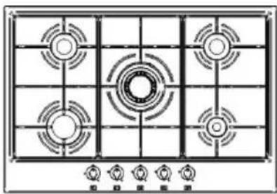
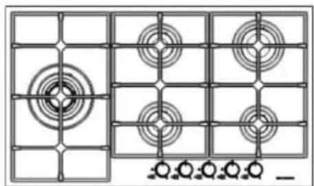
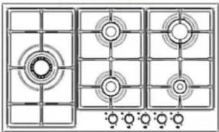
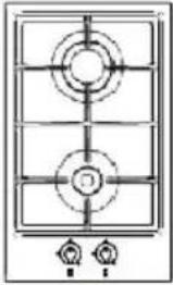
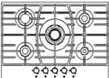
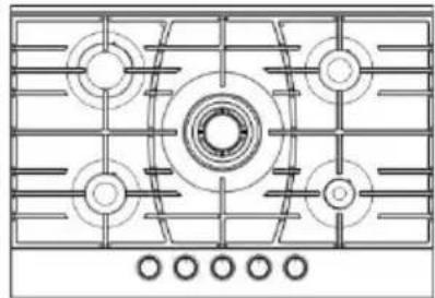
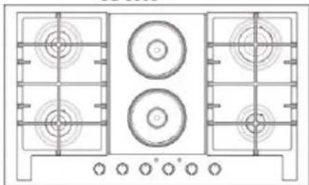
Top-down schematic of a gas stove with four numbered windows and control knobs (no text or labels)AS 5274
OCAKLARIN KULLANIMI
GAZ BEKLERİ
natural_image
Five circular diagrams with labeled points and connection lines, no text or symbols presentnatural_image
Five circular diagrams with labeled points and connection lines, no text or symbols presentnatural_image
Two circular diagrams with arrows and plus signs, no text or symbols presentnatural_image
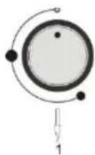
Simple diagram of a circular object with two points and a downward arrow labeled '1' (no text or symbols beyond the number)1.Wok bek düğmesi
natural_image
Simple diagram of a planetary orbit with concentric circles and marked points (no text or labels)Güç kontrol düğmesi
natural_image
Two identical 3D-rendered cooking pots on a black stove, one crossed out by a diagonal line (no text or symbols)natural_image
Illustration of two cooking pots on stovels with crossed steam lines (no text or symbols)natural_image
Two white cooking pots on a stove, one crossed by a black line (no text or symbols)natural_image
Two white cooking pots on a black stove, one crossed with a diagonal line (no text or symbols)natural_image
Isometric diagram of a kitchen appliance with labeled parts (no text or symbols present)natural_image
Technical line drawing of a 3D electrical socket with four fans and a close-up inset showing internal components (no text or symbols)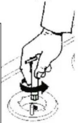
natural_image
Hand holding a tool with a circular base, no text or symbols visiblenatural_image
3D mechanical assembly diagram showing internal components and labeled parts (no text or symbols present)1 Nitril/ Klingirik Conta
2 Dirsek
3 LPG Hortum Girişi
natural_image
Simple geometric symbol with a circle and two crosshairs inside a rounded square (no text or labels)EN Built-in Hob User Manual
SILVERLINE®
Our Valued Customer,
Thank you for your purchase of our product.
Please read all instructions and warnings in this manual carefully. This manual includes the important information about safe installation, usage and maintenance and the required warnings for your utilization of your equipment.
Please keep this manual at a safe and easily accessible place to be used as future reference.
The producer may not be held liable for the losses to human, environment or other materials arisen from the faulty use of the equipment arisen from the translation or printing of this manual.
CONTENTS
SAFETY INFORMATION....1
GENERAL SAFETY WARNINGS ....3
SAFETY OF THE GAS ....5
TECHNICAL PROPERTIES OF HOB....7
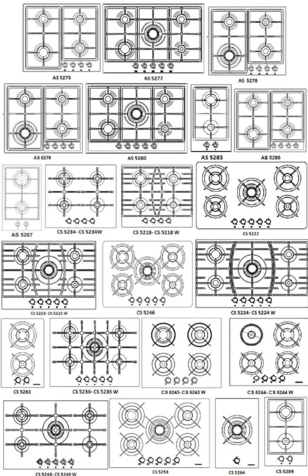
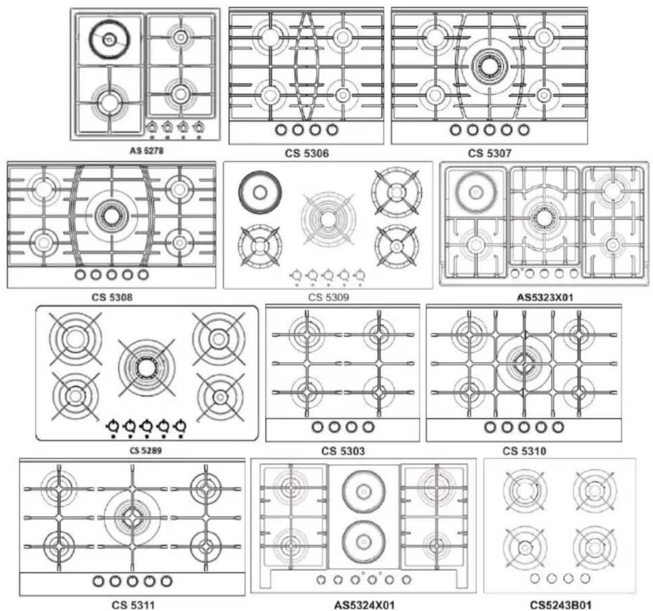
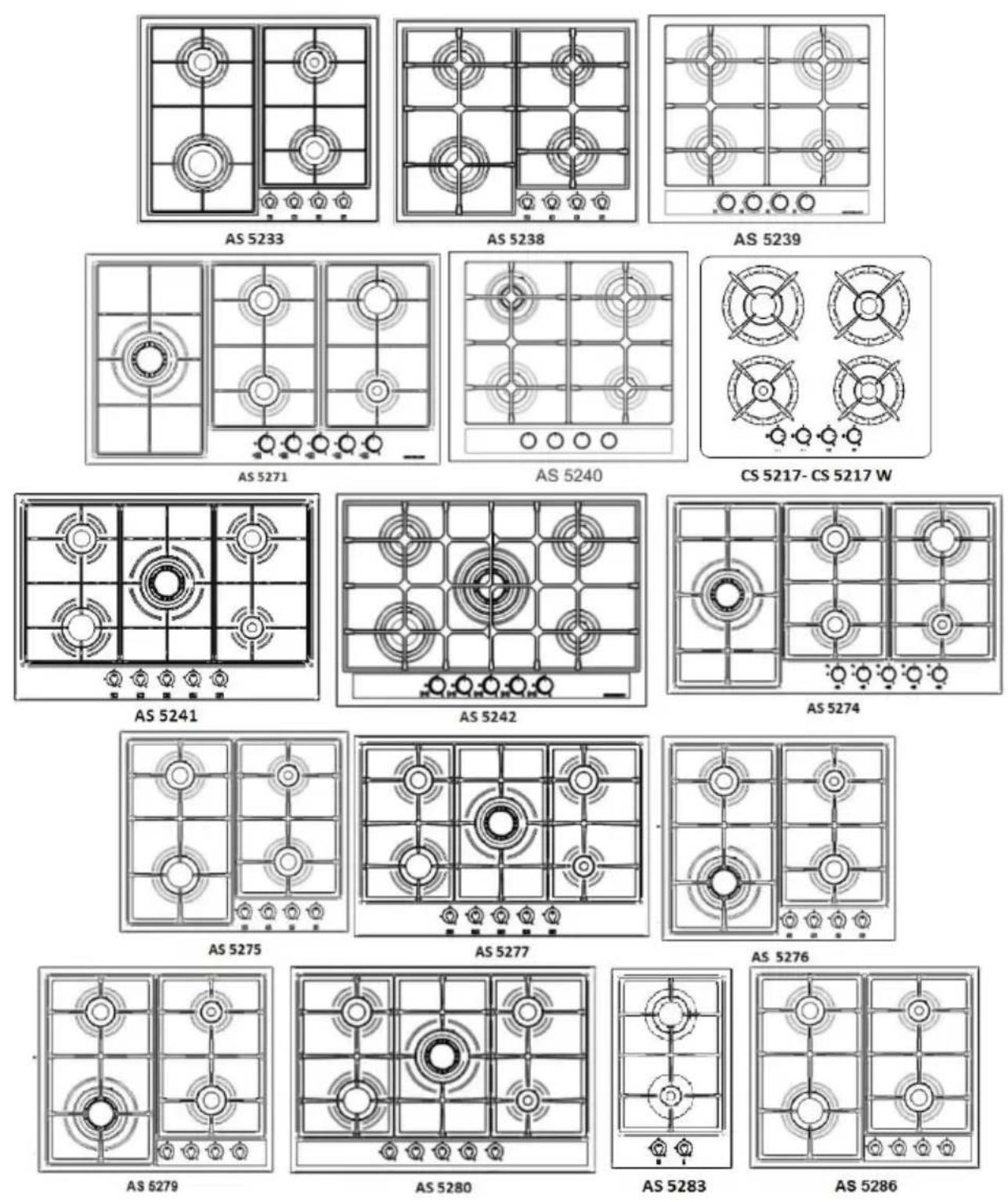
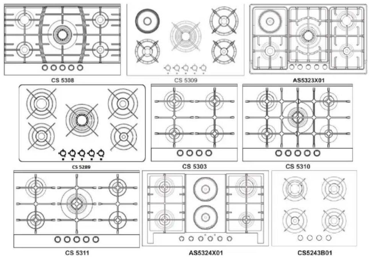
MODELS....9
USAGE OF HOBS 11
UTILIZATION OF HOT PLATE 16
INSTALLATION OF THE UNIT....20
INSTALLATION INFORMATION ON THE UNIT ......21
ELECTRIC CONNECTION 25
GAS CONNECTION....26
ADJUSTMENT OF HOB PER GAS TYPES....28
TECHNICAL INFORMATION ON GAS BURNERS ......29
HOB'S ENERGY EFFICIENCY....30
CLEANING AND MAINTENANCE ....30
This device is produced for domestic use. Our firm is not liable for any losses or damages which may occur due to wrong or faulty installation.
Although this is a simple use product, we recommend you to read this manual carefully. In this sense, you may get best performance from your device and protect yourself and your surrounding from the possible dangers.
Please consider the following warnings in order to minimize the risks which may be experienced by you in utilization of the devices such as electric shock, circumstances which may cause losses/ damages to people.
• Device is set to 220 -240 volt.
- WARNING: The equipment
• and its accessible parts are hot during use.
- Best care should be used to avoid contacting with the heating elements.
- If constant supervision may not be provided the children under age 8 shall be kept away of the unit.
- This unit may be used by children over 8 years old and the persons with lack of physical, hearing or mental abilities or lack of experience and information, subject to guidance and supervision or utilization of the unit safely and recognition of the dangers.
• Children should not play with the unit.
- Cleaning and maintenance of the unit should not be conducted by the children without supervision.
- WARNING: Cooking with vegetable oil or fat without required care may be dangerous and may cause fire.
- Do not attempt to extinguish any fire with water, the circuit of the equipment is closed and then the flame is covered with a cover or flame blanket.
- WARNING: Fire Danger: Do not store materials on cooking surface.
- The accessible parts may be hot during utilization.
- Do not ever clean your hob by using steam cleaners.
- The equipment is not designed to be operated with an external timer or a separate remote control.
- Do not use the unit in circumstances affecting your judgment such as being drank or drugged.
- Since your device has grounding plug your wall socket should also be grounding type.
- Use utmost care to prevent your device's electrical cable through hot areas.
- Use care that the gas hose will be TSE stamped, not be laid through hot areas, and it should be checked with soap bubble whether any gas leakage exists.
- Use clamp to tighten the gas hose after connecting it to the head of the hose. Control whether there is any gas leakage exists by using soap bubble.
- Note that the LPG hoods should have TSE stamp and 300 mmSS (30mbar) of outlet pressure.
- Natural gas pressure is 200 mmSS (20mbar). Please consult the authorized service for conversion to natural gas or LPG.
- Note: Usage of the gas baking products shall cause heat and steam formation at the places of existence. Be sure that your kitchen is ventilated well. Keep the natural ventilation outlets open or install a mechanical ventilation product (hood, aspirator).
Note: Burners' flame setting can be adjusted between a maximum and a minimum value.
GENERAL SAFETY WARNINGS
- Make sure that you remove all packaging materials before using the unit.
- When you remove the hob from the package make sure that hob and / or the cable is full and undamaged, and no impact was put at the bottom of the device, otherwise consult your seller.
- Since this unit was produced for domestic use, it is not suitable for commercial and industrial use. It is dangerous and inappropriate to use it for any other purpose (e.g. heating a room).
- Do not allow laying of the gas hose and electric cord from the heated part of the unit.
- Keep any flaming, explosive and ignition materials from your device.
- Do not change the place of your device when working and/or it is hot.
- When you do not use your hob, close the feeding valve after making all switches to "OFF" position.
- Do not let your hob in operation without supervision control it with frequently.
- Take out the plug from the wall socket during handling, cleaning or maintenance of the unit.
- Do not ever attempt to remove the cable from the wall socket by handling the cable.
- Do not touch or operate the unit when your hands or feet are wet.
- For the hobs supplied with glass: if the glass of your hob will crack and/or break remove the device from the wall socket.
- Do not use pans transferring the excessive heat to the glass.
- Place the pan right in the middle of the burner.
- Do not place any sharp object on the hob.
- Keep the pan on the hob carefully and avoid dropping it.
- The shapes in this guide are schematic and may not be exact match of your product. The values stated on the marking on the unit or other printed documents given with the unit are the values obtained at the laboratory pursuant to the applicable standards. Such values may be changed as per the usage and environment conditions of the unit.
- Do not heat the closed cans and glass jars. The pressure which may occur in such containers may cause explosion.
- Since the edges of the product will be hot do not place explosive or combustibles near the unit.
- Do not place the empty pans and containers on the operating hob eyes. The glass surface may be damaged.
- No plastic and aluminum container is allowed over the unit since it might be hot.
SAFETY FOR CHILDREN
- The exposed parts of the product shall be heated during and after the use; the children should be kept away.
- Do not place any object on the unit that the children may reach.
- Packaging materials may be dangerous for children. Keep the packaging materials in a place that the children may not reach or classify and recycle them as per the waste instructions.
SAFETY OF THE GAS
- Any and all works on the gas equipments and systems should be conducted by the competent and authorized persons.
- Gas hobs cause heat and steam formation at the environments in which they are used.
- Make sure that your kitchen ventilated well. Keep the natural ventilation channels open or use ventilation product (hood).
- Have the required maintenance of the gas products by the competent and authorized persons.
- Clean the gas burners regularly.
- Request the telephone numbers from the local gas suppliers for emergency cases.
Things to be done when gas smells
- Do not use flame. Do not smoke Do not operate the switch of any electrical device. Do not use fixed or mobile phone.
- Close all valves on the gas products and gas counters.
- Open the doors and windows.
- Go out of the house if you smell gas still.
- Warn the neighbors.
- Cal the fire service. Use a phone outside the home.
-
Do not enter the house until you will be notified that it is safe.
-
Keep the original packaging of the product.
- Carry the product in its original packaging, and abide the markings thereon.
- If the original packaging is not available;
√ Take care for the impacts which may be applied on the outer surfaces of the product.
√ Place/ hold the product in parallel to the ground during carrying (as the upper side will be up).
√ Carry the pan holders not touching each other.
Packaging
All packaging materials are recyclable. In order to contribute environmental protection place the packaging material wastes to the recycling bins.
natural_image
Abstract circular arrow diagram with no text or symbolsDisposal of the old equipments
The equipments being old and useless should not be thrown to a waste container directly. There may be some parts allowing reuse. Also there may be some environmentally dangerous materials requiring to be given to a collection center. Therefore you should take your unit to a collection center that you may learn from the manufacturer/ dealer in your city and insure that the electronic parts will be recycled.
It is important to keep the user's manual for it will be important in the event of change of the user of the device.
Before disposal or scraping of the device it is required to prevent harmful and negative effects on human and environment.
Otherwise it would be incompliant waste.
This symbol indicates that the unit should not be disposed as domestic waste rather it should be returned to some electronic wastes collection center. The disposal of the product should be conducted as per the local environmental legislation. You may obtain detail information on disposal, reuse and recycling of the product.
natural_image
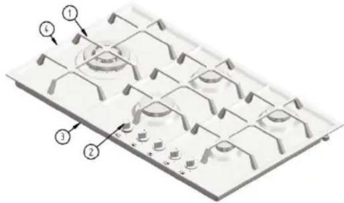
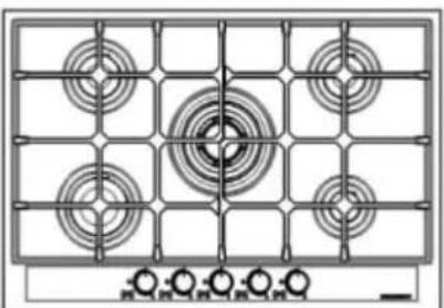
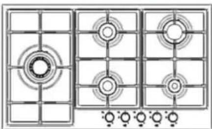
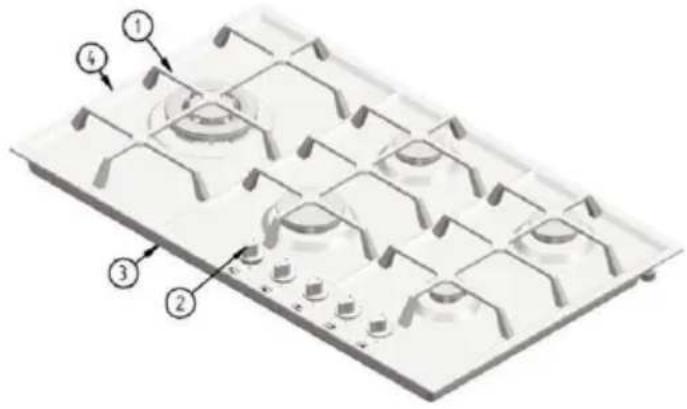
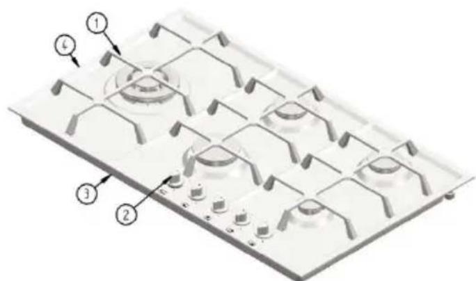
Symbol of a trash bin crossed with two crossed lines, no text or labels presentTECHNICAL PROPERTIES OF HOB
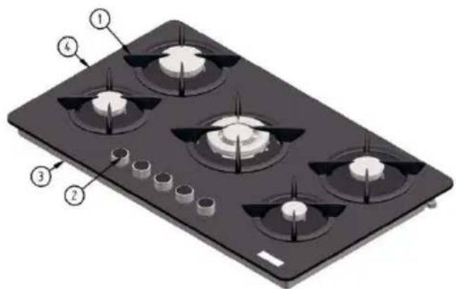
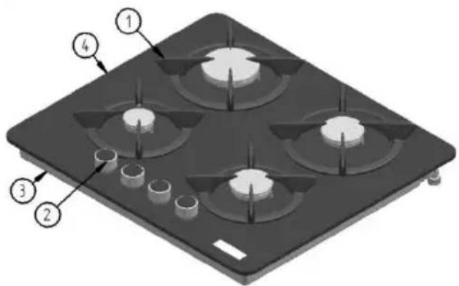

- Pan supports
- Control switches
- Hob bottom plate
- Top plate
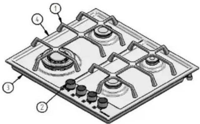
* There is FFD available in the all models supplied inside Turkey.
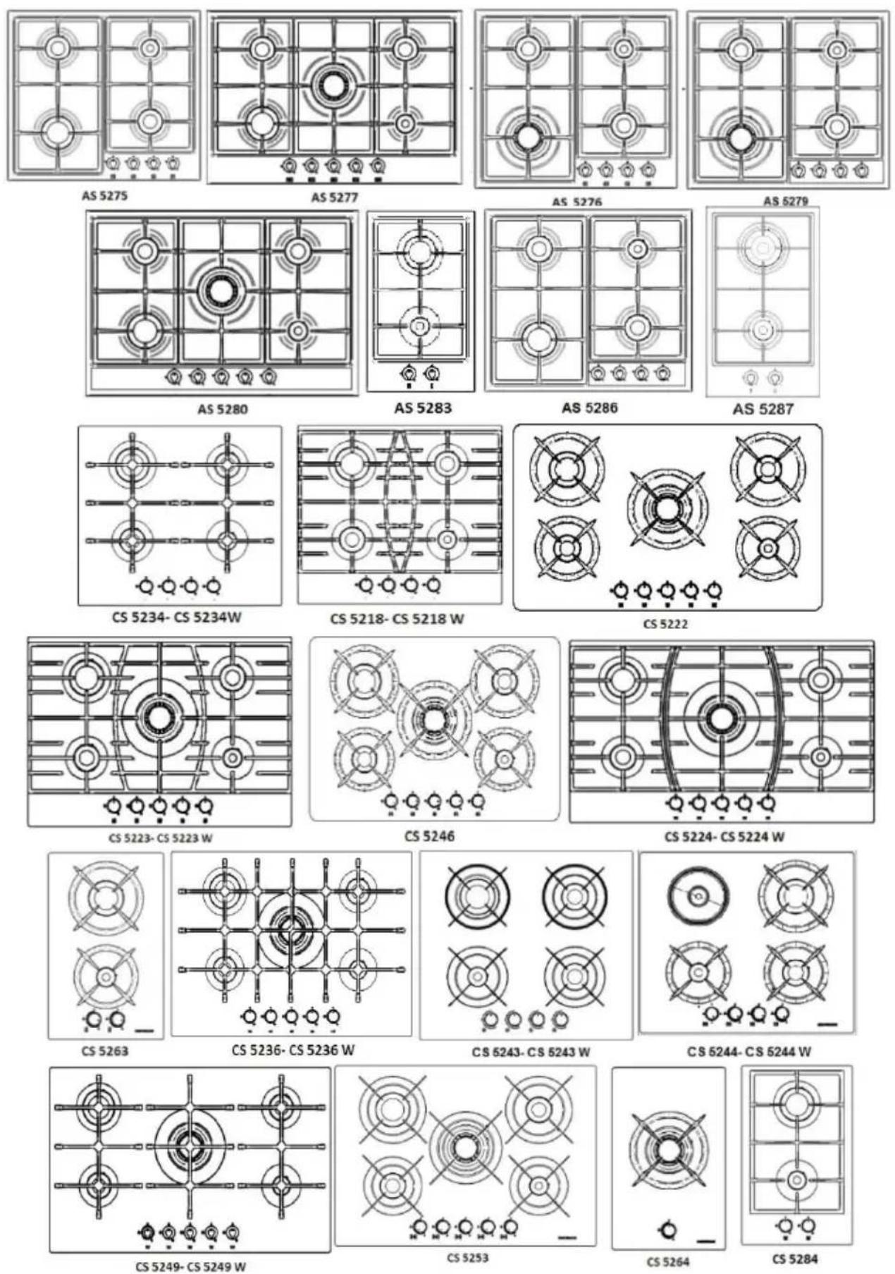
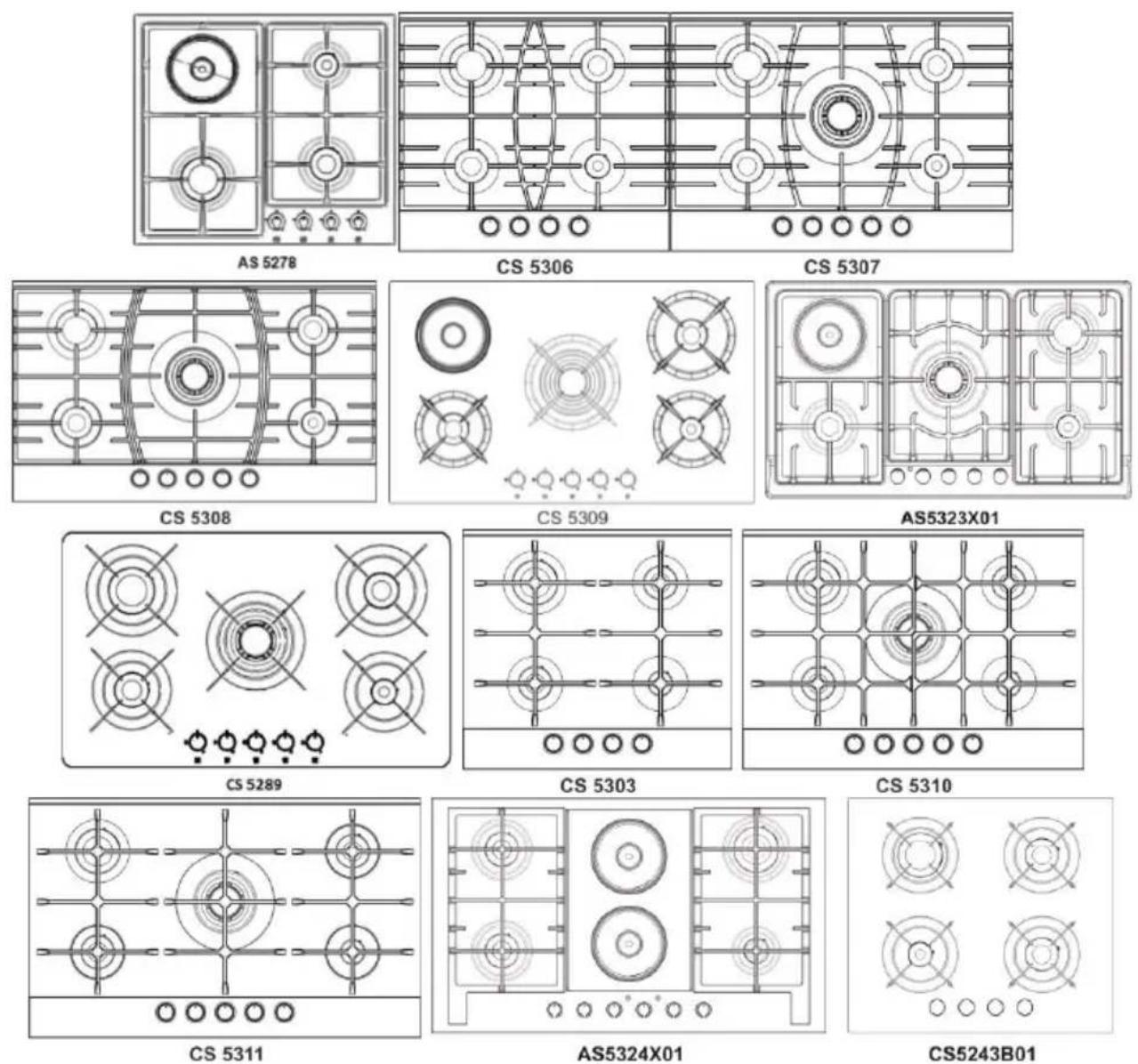
| MODELS | |||||||||||
| CS 5222 - CS 5224CS 5224 W- CS 5289CS 5249 - CS 5249 WCS 5246 - CS 5223CS 5223 W - CS 5236CS 5236W - CS 5253CS 5307-CS 5308AS 5241- AS 5215AS 5242 - AS 5216AS 5271- AS 5274AS 5277- AS 5280CS 5310- CS 5311 | CS 5309AS5323X01 | CS 5243CS 5243 WCS 5217CS 5217 WCS 5218CS 5218 WCS 5234CS 5234 WCS 5306CS 5303CS5243B01 | AS 5233AS 5238AS 5239AS 5275AS 5286 | AS 5214AS 5276AS 5279 | CS 5244CS 5244 WAS 5278 | AS 5283AS 5287CS 5284 | AS 5240 | CS 5264 | CS 5263 | AS5324X01 | |
| Number of Burners | 5 Gas Burners | 4 Gas Burners | 4 Gas Burners | 4 Gas Burners | 4 Gas Burners | 4 Gas Burners | 2 Gas Burners | 4 Gas Burners | 1 Gas Burners | 2 Gas Burners | 4 Gas Burners |
| Auxiliary Burner (A)(1 kW) | 1 Unit(s) | 1 Unit(s) | 1 Unit(s) | 1 Unit(s) | 1 Unit(s) | 1 Unit(s) | 1 Unit(s) | 1 Unit(s) | - | - | 1 Unit(s) |
| Semi Rapid Burner(SR) (1,75 kW) | 2 Unit(s) | 2 Unit(s) | 2 Unit(s) | 2 Unit(s) | 2 Unit(s) | 1 Unit(s) | - | 1 Unit(s) | - | 1 Unit(s) | 2 Unit(s) |
| Rapid Burner (R)(3 kW) | 1 Unit(s) | - | 1 Unit(s) | 1 Unit(s) | - | 1 Unit(s) | 1 Unit(s) | 1 Unit(s) | - | 1 Unit(s) | 1 Unit(s) |
| Triple Burner (3,3 kW) | - | - | - | - | - | - | - | 1 Unit(s) | - | - | - |
| Triple Burner (3,8 kW) | 1 Unit(s) | 1 Unit(s) | - | - | 1 Unit(s) | - | - | 1 Unit(s) | - | - | |
| Hot Plate Burner | - | 1500 W | - | - | - | 1500 W | - | - | - | 2x1500W | |
| Total Power | 11.3 kW | 9.8 kW | 7.5 kW | 7.5 kW | 8.3 kW | 7.25 kW | 4 kW | 9.05 kW | 3.8 kW | 4.75 kW | 10.5 |
| Gas ConsumptionG20-20mbar | 1077 l/h | 791 l/h | 715 l/h | 715 l/h | 791 l/h | 548 l/h | 381 l/h | 863 l/h | 362 l/h | 453 l/h | 715 l/h |
| Gas ConsumptionG30-30mbar | 822 g/h | 604 g/h | 545 g/h | 545 g/h | 604 g/h | 418 g/h | 291 g/h | 657 g/h | 277 g/h | 345 g/h | 545 g/h |
| Gas Category | II2H3+ | II2H3+ | II2H3+ | II2H3+ | II2H3+ | II2H3+ | II2H3+ | II2H3+ | II2H3+ | II2H3+ | II2H3+ |
| Installation Class | 3 | 3 | 3 | 3 | 3 | 3 | 3 | 3 | 3 | 3 | 3 |
| Electric Supply | 220-240 V 50-60 Hz | 220-240 V50-60 Hz | 220-240 V50-60 Hz | 220-240V50-60 Hz | 220-240V50-60 Hz | 220-240V50-60 Hz | 220-240V50-60 Hz | 220-240V50-60 Hz | 220-240V50-60 Hz | 220-240V50-60 Hz | 22O-240V50-60Hz |
| Gas Cut Safety | Optional* | Optional* | Optional* | Optional* | Optional* | Optional* | Optional* | Optional* | Optional* | Optional* | Optional* |
| Supply Cable | YES | YES | YES | YES | YES | YES | YES | YES | YES | YES | YES |
| Automatic Ignition | YES | YES | YES | YES | YES | YES | YES | YES | YES | YES | YES |
| Product measurements | CS 5222-CS 5224-CS 5224 W-CS 5289CS 5249-CS 5249W860x520 mmAS 5216- AS 5271AS 5274860x510 mmCS 5246-CS 5223-CS 5223 W-CS 5236-CS 5236W-CS 5253750x520 mmAS 5241- AS 5215AS 5242- AS 5277AS 5280750x510 mmCS 5307-CS 5310750x523 mmCS 5308-CS5311860x523 mm | CS 5309860x520mmAS5323X01860x510mm | CS 5243CS 5243 WCS 5217CS 5217 WCS 5218CS 5218 WCS 5234CS 5234 WCS5243B01590x520mmCS 5306CS 5303590x523mm | 580x510mm | 580x510mm | CS 5244CS 5244W590x520mmAS 5278580x510mm | CS 5284320x520mmAS 5283AS 5287305x510mm | 580x510mm | 320x520mm | 320x520mm | 860x510mm |
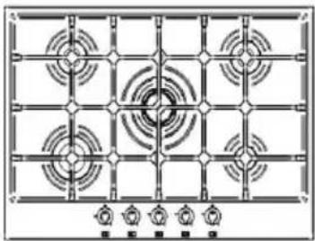
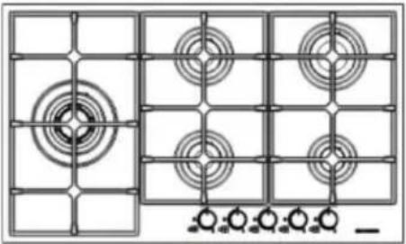
MODELS
natural_image
Pure electrical circuit lines without any symbolsAS 5214
natural_image
Pure electrical circuit lines without any symbolsAS 5215
natural_image
Grid pattern with concentric circles and a central circle, no text or symbols presentAS 5216
natural_image
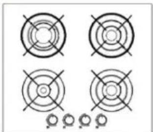
Line drawing of a two-position electric stove with four circular vented lights (no text or symbols)AS 5233
natural_image
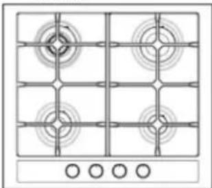
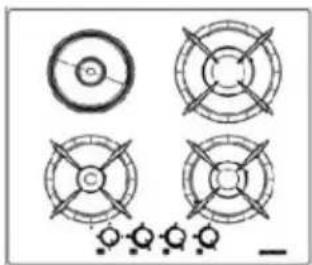
Technical line drawing of a four-panel kitchen appliance with circular vented zones and control knobs at the bottom (no text or symbols)AS 5238
natural_image
Pure electrical circuit lines without any symbolsAS 5239
natural_image
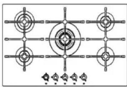
Technical diagram of a gas stove with four circular components and grid lines (no text or labels)AS 5271
natural_image
Top-down schematic of a four-panel kitchen appliance with circular vented lights and control buttons (no text or symbols)AS 5240
natural_image
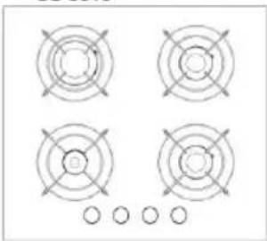
Four circular mechanical components with cross-shaped cutouts, arranged in a 2x2 grid (no text or symbols visible)CS 5217-CS 5217 W
natural_image
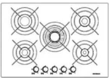
Top-down schematic of a gas stove with four circular vented fans and a central circular chamber (no text or labels)AS 5241
natural_image
Grid pattern with concentric circles and rectangular boundaries, no text or symbols presentAS 5242
natural_image
Technical diagram of a four-panel kitchen appliance with circular components and control knobs (no text or labels)AS 5274
USAGE OF HOBS
GAS BURNERS
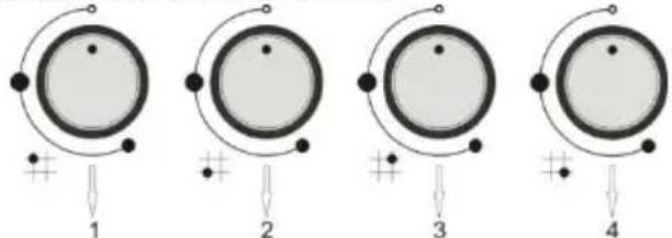
Gas is supplied to the burners by turning the switches. Although the symbols change from model to model, they are indicated either on the switches or the control panel. The following settings may be conducted to match with the illustrated symbols.
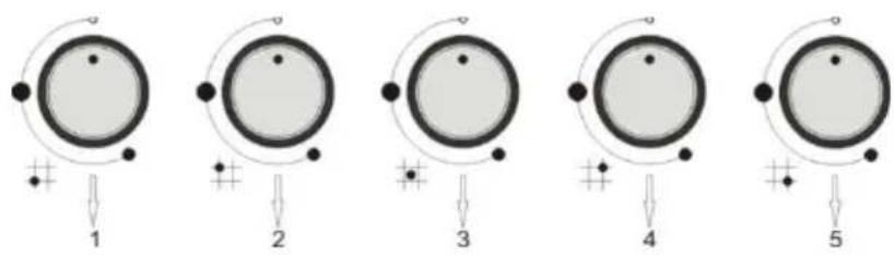
- Left lower burner control switch
- Left upper burner control switch
- Medium burner control switch
- Right upper burner control switch
- Right lower burner control switch
natural_image
Five circular diagrams with labeled points and connection lines, no text or symbols present- Left burner control switch
- Medium lower burner control switch
- Medium upper burner control switch
- Right upper burner control switch
- Right lower burner control switch
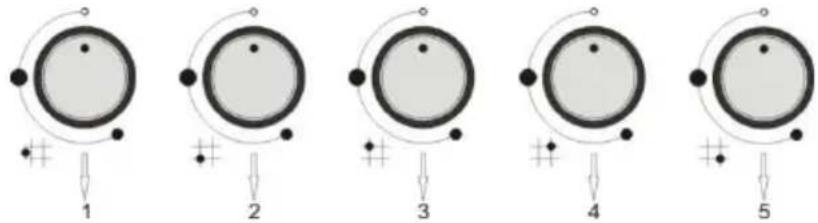
natural_image
Four circular diagrams with arrows and dots, no text or symbols present- Hot-plate control switch
- Left lower burner control switch
- Right upper burner control switch
- Right lower burner control switch
natural_image
Four circular diagrams with plus signs and connecting lines, no text or symbols present- Left lower burner control switch
- Left upper burner control switch
- Right upper burner control switch
- Right lower burner control switch
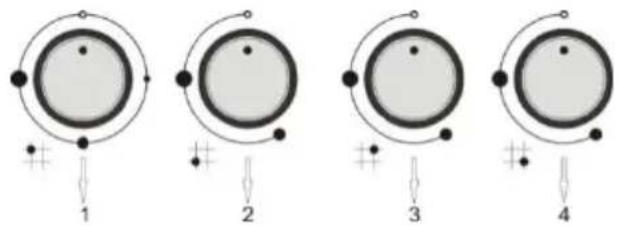
natural_image
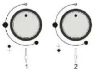
Two circular diagrams with arrows indicating rotation and polarity, no text or symbols present- Upper burner control switch
- Lower burner control switch
- Wok burner control switch

- Left lower burner control switch
- Left upper burner control switch
- Upper hot-plate control switch
- Lower hot-plate control switch
- Right upper burner control switch
- Right lower burner control switch
FIRING OF BURNER
If your hob does not have built in lighter or during black out place the naked flame over the burner and push the switch to bring it to the desired position with counter-clockwise movement. Gas adjustment should be between maximum and minimum levels, it should not be realized between maximum and off positions. To close the burner turn the switch clockwise till to reach “off” position.
MODELS EQUIPPED WITH LIGHTER SWITCH (Automatic ignition)
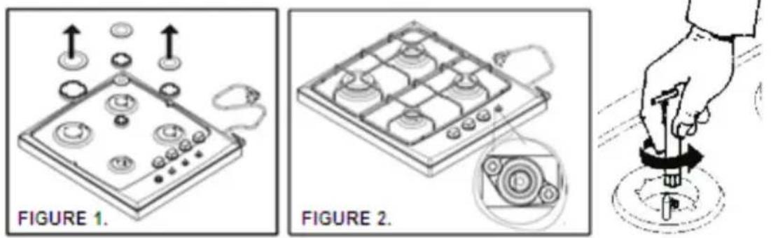
In order to burn one of the burners, press the switch down and bring the switch to maximum position. When it burns, flame is adjusted to the desired intensity with the switch.
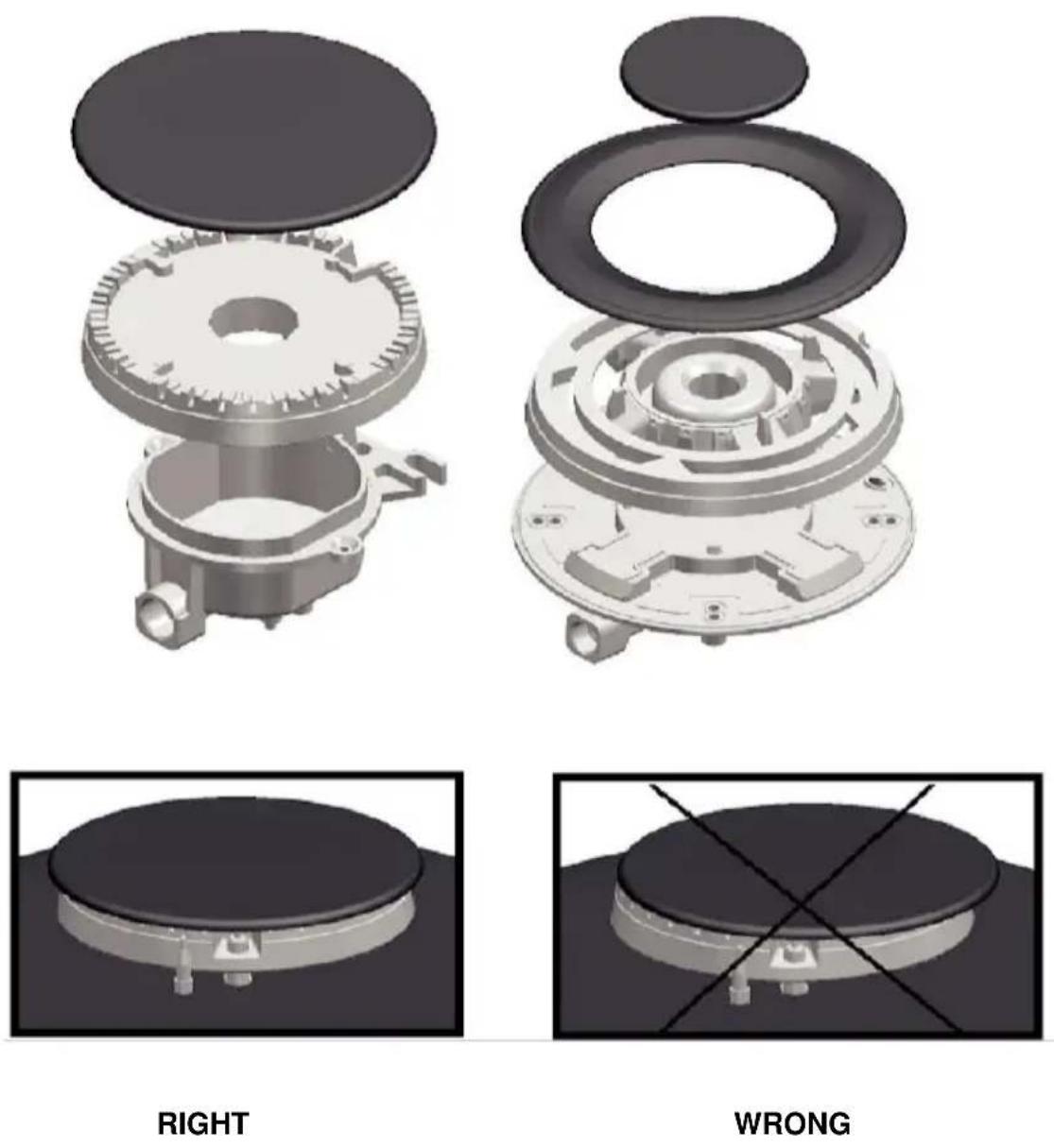
Figure 1.
- In order that the hob will operate properly the grills and burner components should be properly positioned.(Figure 1)
- Make sure that the flame of your burner is in blue color and work quietly. If the burner will burn in yellow color or work with voice make sure that all burners fit properly. If the flame color does not change to blue color then apply the authorized service.
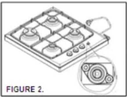
Operation of the burners and power levels
Turn the control switch left-wise until reaching to maximum level. When you press the control switch all burning igniters will have
flame to burn. Release the switch in few seconds after burning of the burner, and bring the control switch to the desired flame position between the maximum and minimum levels. (Figure 2)
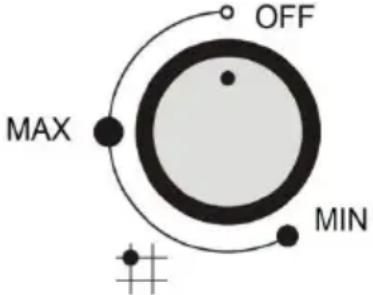
Figure 2.
If the flame is gone when you release the switch You should repeat the above process. But this time press the switch and hold for about 10 seconds.
WARNING;
Do not use burning system more than 15 seconds. If the burner will not be burned within such time or if the flame will be cut for any reason whatsoever, repeat burning process after waiting for 1 minute.
Closing the burners
Turn the control switch right-wise to close the hob.
Flame Failure Device (FFD)
All burners on your hob are equipped with Flame Failure Device system against flame extinguishing risk (water flow, wind etc.) When the flame died down while the burner switch is open such system will provide cutting of the gas supplied to the burner. If the burning of the burner will be cut due to safety, repeat the burning operation by switching the burner switch to off position.
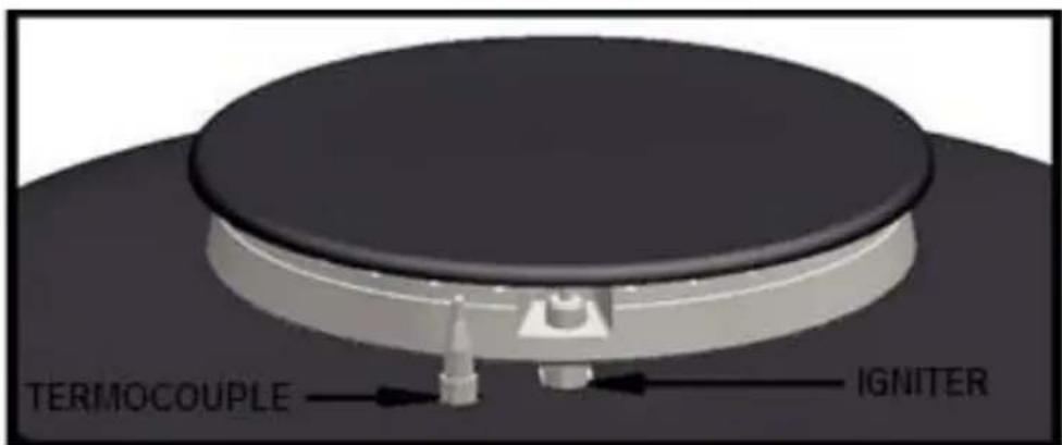
Figure 3.
UTILIZATION OF HOT PLATE
Warnings
Before use of electrical plate the plate should be elevated to the maximum level and rest it for 5 minutes without putting any container thereon. It is Ok if any smell or smoke will rise from the plate. Such effects shall disappear after starting normal use.
After such first use do not operate the electrical plate without any container thereon.
Use the containers with the bottoms being thick and suitable for the plate size. Never use smaller sole containers.
Pay attention that no liquid and wet containers will be placed on the plate.
Avoid any contact of any vinegar, salt, lemon juice etc. with the plate.
Do not use any spatula and similar sharp objects in cleaning of joints between the glass and metal surfaces or aluminum parts on the hob.
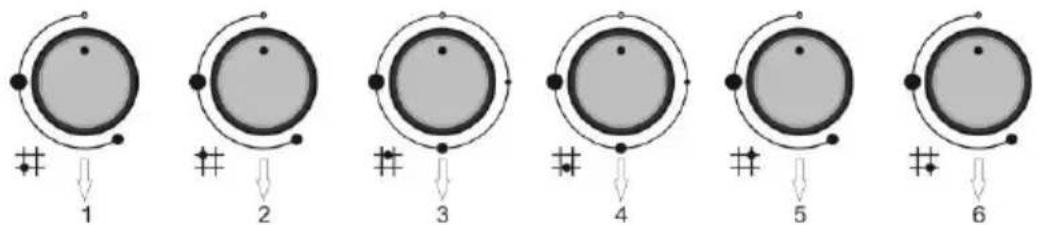
Usage
natural_image
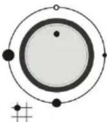
Diagram of a planetary orbit with concentric circles and marked points (no text or labels)Power control switch
Electrical plate is managed with a switch with which you may select proper power for the food you will cook.
Turning on the Plate:
Bring the control switch to the proper position by turning it to right or left by the cooking type, food quantity and using below scheme. The red warning light will be on when the switch is set to any value other than off position.
To close the plate:
Bring the control switch to 0 position. The warning light will go off.
| 1 ● | Low | Heating |
| 2 ● | Medium | Quick heating and cooking |
| 3 ● | High | Frying |
The positions recommended are only for guiding purposes. The power should be increased at the following situations:
- In the event of cooking by using plenty of liquid
- In big portions
- With cooking under the lidless containers
Suggestions
If the surface of the plates worn a few drops of oil or maintenance products available in the market may be used.
It is recommended to set maximum level at the beginning of cooking process and to use intervals and burning levels as per the characteristic and quantity of the foods to be cooked.
Using Right Burner
- The pan diameter and the burner power should match in order to efficiently use it. The diameters proper for each burner are given in the table.
- Select the proper pan diameter and volume in order to define the proper burner.
| Pan Diameters | ||
| Burners | The Smallest Diameter (cm) | The Largest Diameter (cm) |
| Auxiliary Burner(A) | 12 | 16 |
| Semi Rapid Burner (SR) | 14 | 20 |
| Rapid Burner (R) | 18 | 24 |
| Triple Burner | 22 | 26 |
| Hot Plate Burner | 14 | 18 |
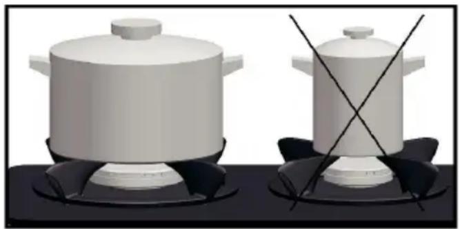
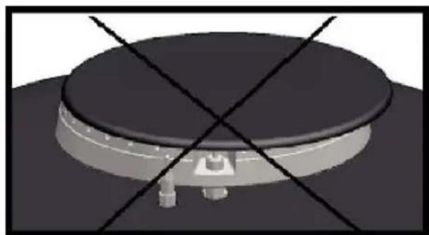
Usage of grills and recommendations
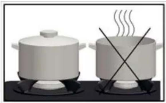
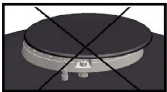
The pan grills on the hob are designed for safe use of the hob. Please make sure that the grills are placed properly and plastic legs fit well.
- Do not use pans with the deformed soles which may cause instability on the grills.
natural_image
Two identical 3D-rendered cooking pots on a gas stove, one crossed with diagonal lines (no text or symbols)- Do not cook with pans without lid or semi closed pans to avoid energy loss.
natural_image
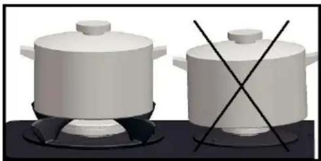
Illustration of two cooking pots on a stove with crossed x-metty lines indicating heating (no text or symbols)- Do not place the containers directly on the burner covers use grill always.
natural_image
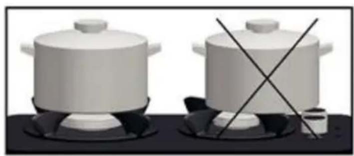
Two white cooking pots on a stove, one crossed with black lines (no text or symbols)- Place the cooking pan on the burner evenly. The containers placed on the burner inappropriately may be tipped. Do not place the large containers at the side of the switch switches may be damaged. Do not place the pans on the grills hardly.
natural_image
Two identical 3D-rendered cooking pots on a stovetop with one crossed and one uncoiled (no text or symbols)- Pay attention that the burner place will not have any impact. And do no place heavy objects on the grill.
- Do not heat the pans as empty. The pan sole may be deformed. The heat on the sole may damage the hob's top plate surface.
- The cold liquids should not be thrown on the glass surface or burners when the surface is hot.
- Do not place sharp objects on the hob.
- Do not use pans transferring the excessive heat to the bottom surface directly.
- In the event of any fire do not attempt to extinguish the flames with water. Close the electric circuit of the hob and use a material to cut the flame like flame blanket.
- This device should not be operated with a timer or a remote control.
Warning;
- Do not leave the equipment unattended since the heat of burners is very high, and make sure that it will not be operated by children.
- Pay attention for combustion risk in the event of cooking with vegetable oil and fats.
- Do not approach the hob with combustible and explosives.
INSTALLATION OF THE UNIT
The installation should be conducted by an authorized service dealer as per the installation instructions. Our firm may not be held liable for any losses and damages to human, animals or objects due to any inappropriate use of the unit.
PRE-INSTALLATION WARNINGS
ATTENTION: Before the installation check that the gas type and gas pressure stated under the product fit those of your home. Call the authorized service dealer for possible gas type changes in future.
- When the unit was taken off its packaging make sure that it is strong, not bent and has no fault at all. In the event of any doubt consult the dealer.
- Cut off the electric connection of the unit from the main switch during installation.
- In order that built in cook-tops will operate smoothly the measurements of the counter on which it will be mounted and the materials used for installation should be proper, and the counter should be resistant against heat.
Read the following instructions to fix the hob on the counter:
In order to prevent insertion of the foreign materials and liquids between the hob and the counter attaché the adhesive band on the counter hole without allowing any overlapping before the installation.
Place the hob on the counter hole to center the installation hole.
Secure the unit on the counter by using the installation sheet and screws.
Please review the following figures carefully so that the hob will be installed properly.
INSTALLATION INFORMATION ON THE UNIT
This equipment should be mounted at the well ventilated places and as per the regulations in force. The installation personnel should consider the laws and norms applicable to the release of burning gases and ventilation.
- Your hob is designed to be installed on the standard counters which you may find in the market.
-
The materials used on the surface and the link partitions under the counter should be resistant against minimum 100°C.
-
A safe distance should be left between the hob and the counter walls (Figure 4).
- The hole to be provided for the hob on the counter should be as per the figure. (Figure 4)
- The distance between the hob sole and the partition should be at least 25 mm. (Figure 5)
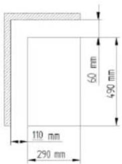
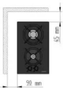
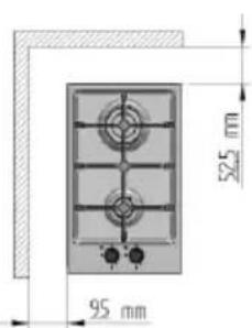
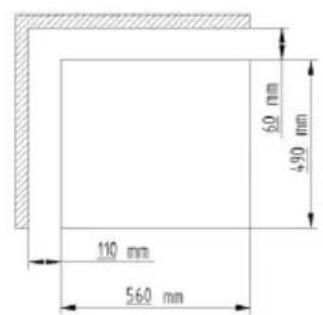
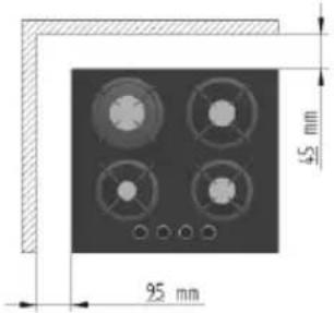
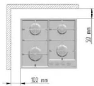
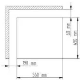
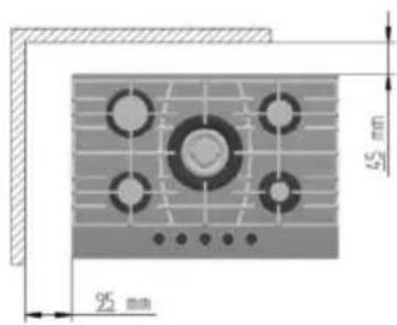
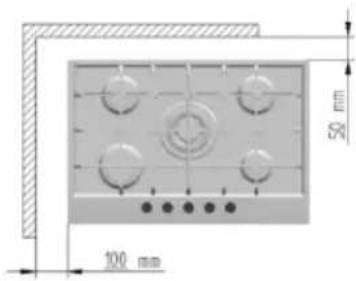
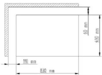
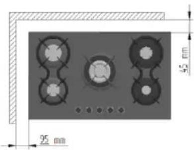
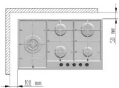
Figure 4.
- The distance between the cook top ad another device (e.g. kitchen hood) shall not be less than 700mm(Figure 5).
- If 60 cm Hobs will be placed on a built-in oven without any cooling system, it is recommended to leave 300 cm 2 of ventilation hole in order to insure air circulation. If 75 or 90 cm cook-top will be placed the oven has to have cooling fan.
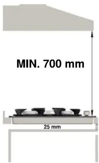
Figure 5.
Release of Burnt Gases
- The air required for burning is taken to the environment of the hob and the burnt gas are released to the environment. Proper ventilation should be maintained for safe operation of the unit. The ventilation openings defined as per the volume of the environment are provided at the bale (Table 1).
- Burnt gases should be discharged outside by the hood with flume.
- If no kitchen hood is used, an electrical ventilator should be used having guaranteed capacity to discharge 3-5 times of the kitchen air to be installed at the wall or window of the building (Figure 6)
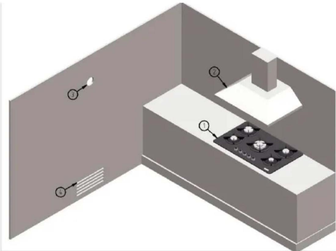
- Cooktop
- Aspirator
- Electrical ventilator
- Ventilation Opening
Figure 6.
| VOLUME OF THE ROOM (m3) | VENTILATION OPENING (cm2) |
| Less than 5 m3 | Minimum 100 cm2 |
| Between 5m3and 10 m3 | Minimum 50 cm2 |
| Larger than 10 m3 | Not required |
| Basement or Cellar | Minimum 65 cm2 |
Table 1
Installation of the Hob on the Counter
- In order to prevent insertion of the foreign materials and liquids between the hob and the counter attaché the gasket on the
counter hole without allowing any overlapping before the installation. (Figure 7)
- Place the hob on the counter hole to center the installation hole.
- Secure the unit on the counter by using the installation sheet and screws. (Figure 7 and 8)
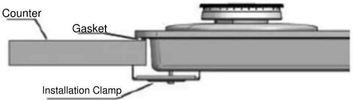
Figure 7.
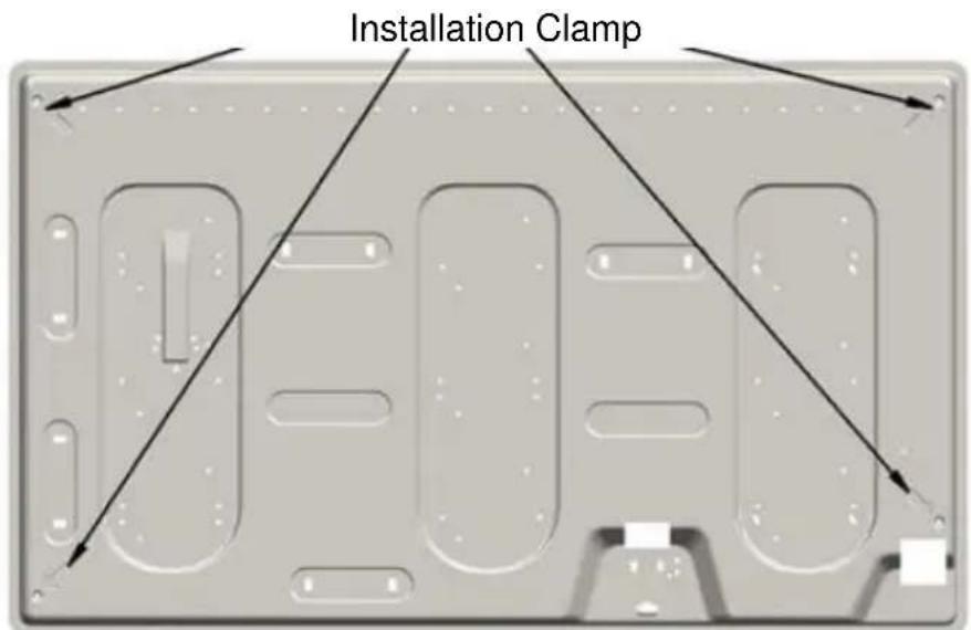
Figure 8.
ELECTRIC CONNECTION
- Electric connection should be conducted by a competent and authorized person.
-
The electric cable of your hob should not be laid at hot regions.
-
When the power cable is damaged this cable should be changed with a special cable to be supplied by a special cable agency or the authorized service dealer.
- No reducer, adapter, and switch should be used for electrical connection since it will cause excessive heat and fire.
- Plug the electric cable to a grounded wall socket. The manufacturer hereby declares that it will be released all liability in the event of any failure in this issue.
- The supply data of the electric network should be suitable with the data on the type label of the unit.
GAS CONNECTION
These instructions are prepared for specialist personnel having required competence, the installation of the equipment should be suitable as per the applicable standards.
All gas related works should be conducted when the electric connection was cut.
The value plate on the hob indicates the gas type intended to be used for use with the hob. Connection to the main gas course or gas type shall be realized after controlling the adjustment as per the gas type. Connection to the main gas source or gas cylinder shall be conducted after checking the adjustment according to the proper gas type. If it is set properly look at the following paragraphs:
Note that the LPG hoods should have TSE stamp and 300 mmSS (30mbar) of outlet pressure.
Natural gas pressure is 200 mmSS (20mbar). Please consult the authorized service for conversion to natural gas or LPG.
Use only piping, gaskets or seal as per the applicable national standards.
In some countries where conic connections are obligatory, conic connection is provided. In such a case the conic connection part should be connected to the unit.
If the unit will be connected to a flexible hose, the length of the hose shall not exceed 120 cm.
Before starting works related to gas installation, please cut the gas supply.
Make the connection so that no pressure will be applied on the connection nuts and piping. Make sure that the pipe will not cause any clogging or contact with the sharp corners.
Note that the gas hose will be TSE stamped, not be laid through hot areas.
NOTE: Replace the gas hose of your hob at 4 to 5 years even if it will be undamaged.
NOTE: Check whether any gas leakage after the connection with soap and water. Do not ever use flame.
Make sure that no additional weight to be applied on the gas hose.
And apply the following order for installation;
- In the order; male adaptor cylindrical, gasket, female gas adaptor, conical-cylindrical or cylindrical cylindrical components,
- Tighten connection place with the keys so that the pipes will be in proper position,
- Attach C coupling to the main gas source by using hard copper pipe or flexible steel pipe.
WARNING; Final Check whether any leakage exists at the pipes with a solution with a soap, and do not ever use flame.
ADJUSTMENT OF HOB PER GAS TYPES
These instructions are prepared for specialist personnel having required competence, the installation of the equipment should be suitable as per the applicable standards.
- All gas related works should be conducted when the electric connection was cut.
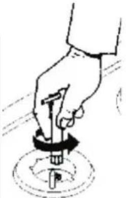
natural_image
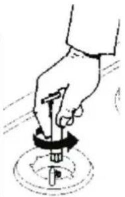
Hand holding a tool with a circular base, no text or symbols visibleIn order to convert the hob, remove the burner plates and flame circles thereon. Replace the injectors as per the followings, and change them with the injectors with suitable diameters defined in the user's manual. Conduct the works with a plain tip screwdriver at a position to see valve setting screw by removing the switches of the hob and rubber seals. In order to set the low flame level, turn the gas setting screw on the valve to have minimum gas setting flow. Do this setting after installing the burner component of the burner, burning the burner and bringing the switch setting to minimum.
Flow setting screw should be tightened in LPG conversions as it should be released for conversion from LPG to natural gas.
After the setting of the hob, complete the conversion procedure by connecting the rubber seals and switches in the same order. These instructions should be used by an authorized service. The products should be installed as per the regulations in force and in proper manner. Before conducting any transaction the electrical connections of the hob should be cut by no means.
The type label on the hob indicates the gas type planned to be
used with the unit.
Note: The burner positions on the burner table are indicated on the burner plate.
natural_image
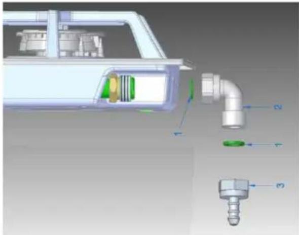
Technical diagram of a car interior showing internal components and labeled parts (no text or symbols present)1 Nitril/Klingerit Gasket
2 Elbow
3 LPG Hose Entrance
Complete the installation by using gasket in the middle for the LPG hose entrance indicated on the above figure during the natural gas LPG conversion.
HOB'S ENERGY EFFICIENCY
- Use flat sole pans on the hob. In this manner, thermal energy shall be used to the maximum.
- It is recommended not to use concave pans.
- Use pans with proper diameters. Do not use smaller pans in the diameter of the burner. When small pans are used it may cause overflowing and reduced the efficiency of the hob.
- Use dry sole pans on the burner. Do not place the cover of the pan and especially the wet ones on the burner.
- Use a wet cloth to wipe the hob. However, if it becomes dirty, use water with detergent to insure drying, apply lubrication oil over it for formation of thin oil substrate.
CLEANING AND MAINTENANCE
Please comply with the following rules before cleaning and maintenance.
- Close the unit for safety purposes. If your device is set to natural gas setting close the valve. For LPG hobs close pressure reducing valve.
• Take out the plug of your unit from wall socket. - If the hob is hot wait until it will be cooled.
-
In order that you use the glass hob and grills for longer periods you need to clean them with appropriate cleaning agents at certain intervals.
-
Cleaning on stainless surfaces should be conducted in accordance with the steel surfaces, and the surface should be dried preferably with a soft leather part.
- In order to avoid any damage to the burning system do not use burning system when the burners are not installed.
- After cleaning of plug and thermocouple, that provides safety system, place the flame spreader on to them dryly.
- Wash the upper burning heads at certain intervals with water and clean and dry the gas channels with brush. Pay attention to install the burning heads on their places.
- When you clean the burner do not use acid, thinner, benzene or similar chemical.
- You need to clean your glass hob and its grills with suitable cleaning agents in order to use it for longer period.
- It should be cleaned with suitable cleaners for stains and oil.
- Harsh cleaning agents, stain removers and detergents, wire wool and sponge should not be used.
- Do not allow heating of the pans as empty since the heat accumulated at the bottom may damage the glass surface.
- No cold liquid should be poured on the glass surface or the burners when they are hot. The glass may crack due to thermal shock.
Clean the hob regularly after waiting for cooling after each use in order to keep your hob at the best manner.
Do not take out the control switches in any manner during cleaning.
Enamel Parts
All enamel parts are used by using water with soap and suitable detergents. The hob should be dried thoroughly after the process.
Pan Supports
Enamel grills may be washed in the dishwasher.
Burner
The burners consisting of two parts may be leaned by using detergent.
The burners should be dried after cleaning process and placed their places delicately.
In the electronic ignition models, the electrode should be left cleaned all the time.
In the safety valve models, the valve should be cleaned for failsafe operation.
After completion of the process, the burners should be placed in their placement to their places.
The burning system should not be used when burners are not in their places to avoid damage to electronic ignition system.
This device, in Europe, accords to the directives 2012/19/EU Waste Electrical and Electronic Equipment. (WEEE) this device prior to disposing of junk and trash, the environment and human health against the potential negative consequences need to block. Otherwise, this would be an inappropriate waste. This symbol on the product, the product treated as household waste, electrical electronic alert is for the delivery of waste collection facilities. The destruction process of the product must be in
accordance with local environmental regulations. To destroy the product, use it again and again for the detailed information for recycling can be obtained from the competent departments.
It conforms to the applicable regulations of WEEE.
PRODUCT FICHE
The information in the product data sheet is given in accordance with the Commission delegated Regulation (EU) No 66/2014 supplementing Directive of the European Parliament and of the Council 2009/125/EC
Informaon for domesc gas-red hobs
| Brand | Silverline | ||
| Model | CS 5246 | ||
| Product Type | Built-in Gas Hob | ||
| Symbol | Rate | Unit | |
| Number of Gas Burner | 5 | ||
| Energy eciency of right rear burner | EE Gas Burner | 60,4 | % |
| Energy eciency of le front burner | EE Gas Burner | 60,4 | % |
| Energy eciency of le rear burner | EE Gas Burner | 59,4 | % |
| Energy eciency of middle burner | EE Gas Burner | 56,9 | % |
| Energy eciency for the gas hob | EE Gas Hob | 59,3 | % |
Informaon for domesc gas-red hobs
| Brand | Silverline | ||
| Model | AS 5271 | ||
| Product Type | Built-in Gas Hob | ||
| Symbol | Rate | Unit | |
| Number of Gas Burner | 5 | ||
| Energy eciency of right rear burner | EE Gas Burner | 57,3 | % |
| Energy eciency of middle front burner | EE Gas Burner | 60,3 | % |
| Energy eciency of middle rear burner | EE Gas Burner | 60,3 | % |
| Energy eciency of le burner | EE Gas Burner | 55 | % |
| Energy eciency for the gas hob | EE Gas Hob | 58,2 | % |
Informaon for domesc gas-red hobs
| Brand | Silverline | ||
| Model | CS 5217- CS 5217 W | ||
| Product Type | Built-in Gas Hob | ||
| Symbol | Rate | Unit | |
| Number of Gas Burner | 4 | ||
| Energy eciency of right rear burner | EE Gas Burner | 60,4 | % |
| Energy eciency of right front burner | EE Gas Burner | 60,4 | % |
| Energy eciency of le rear burner | EE Gas Burner | 59,4 | % |
| Energy eciency for the gas hob | EE Gas Hob | 60,1 | % |
Informaon for domesc gas-red hobs
| Brand | Silverline | ||
| Model | AS 5274 | ||
| Product Type | Built-in Gas Hob | ||
| Symbol | Rate | Unit | |
| Number of Gas Burner | 5 | ||
| Energy eciency of right rear burner | EE Gas Burner | 58,1 | % |
| Energy eciency of middle front burner | EE Gas Burner | 60,1 | % |
| Energy eciency of middle rear burner | EE Gas Burner | 60,1 | % |
| Energy eciency of le burner | EE Gas Burner | 54,3 | % |
| Energy eciency for the gas hob | EE Gas Hob | 58,2 | % |
Informaon for domesc gas-red hob
| Brand | Silverline | ||
| Model | CS 5243- CS 5243 W- CS5243B01 | ||
| Product Type | Built-in Gas Hob | ||
| Symbol | Rate | Unit | |
| Number of Gas Burner | 4 | ||
| Energy eciency of right rear burner | EE Gas Burner | 59,2 | % |
| Energy eciency of right front burner | EE Gas Burner | 59,2 | % |
| Energy eciency of le rear burner | EE Gas Burner | 57,2 | % |
| Energy eciency for the gas hob | EE Gas Hob | 58,5 | % |
Informaon for domesc gas-red hobs
| Brand | Silverline | ||
| Model | CS 5234- CS 5234 W- CS 5303 | ||
| Product Type | Built-in Gas Hob | ||
| Symbol | Rate | Unit | |
| Number of Gas Burner | 4 | ||
| Energy eciency of right rear burner | EE Gas Burner | 56,4 | % |
| Energy eciency of le front burner | EE Gas Burner | 56,4 | % |
| Energy eciency of le rear burner | EE Gas Burner | 58 | % |
| Energy eciency for the gas hob | EE Gas Hob | 56,9 | % |
Informaon for domesc gas-red hobs
| Brand | Silverline | ||
| Model | CS 5236- CS 5236 W- CS 5310 | ||
| Product Type | Built-in Gas Hob | ||
| Symbol | Rate | Unit | |
| Number of Gas Burner | 5 | ||
| Energy eciency of right rear burner | EE Gas Burner | 56,4 | % |
| Energy eciency of le front burner | EE Gas Burner | 56,4 | % |
| Energy eciency of le rear burner | EE Gas Burner | 58 | % |
| Energy eciency of middle burner | EE Gas Burner | 55,2 | % |
| Energy eciency for the gas hob | EE Gas Hob | 56,5 | % |
Informaon for domesc gas-red hobs
| Brand | Silverline | ||
| Model | CS 5249- CS 5249 W- CS 5311 | ||
| Product Type | Built-in Gas Hob | ||
| Symbol | Rate | Unit | |
| Number of Gas Burner | 5 | ||
| Energy eciency of right rear burner | EE Gas Burner | 56,4 | % |
| Energy eciency of le front burner | EE Gas Burner | 56,4 | % |
| Energy eciency of le rear burner | EE Gas Burner | 58 | % |
| Energy eciency of middle burner | EE Gas Burner | 55,2 | % |
| Energy eciency for the gas hob | EE Gas Hob | 56,5 | % |
Informaon for domesc gas-red hobs
| Brand | Silverline | ||
| Model | AS 5233 | ||
| Product Type | Built-in Gas Hob | ||
| Symbol | Rate | Unit | |
| Number of Gas Burner | 4 | ||
| Energy eciency of right front burner | EE Gas Burner | 60,3 | % |
| Energy eciency of le front burner | EE Gas Burner | 57,3 | % |
| Energy eciency of le rear burner | EE Gas Burner | 60,3 | % |
| Energy eciency for the gas hob | EE Gas Hob | 59,3 | % |
Informaon for domesc gas-red hobs
| Brand | Silverline | ||
| Model | AS 5275- AS 5286 | ||
| Product Type | Built-in Gas Hob | ||
| Symbol | Rate | Unit | |
| Number of Gas Burner | 4 | ||
| Energy eciency of right front burner | EE Gas Burner | 60,1 | % |
| Energy eciency of le front burner | EE Gas Burner | 58,1 | % |
| Energy eciency of le rear burner | EE Gas Burner | 60,1 | % |
| Energy eciency for the gas hob | EE Gas Hob | 59,4 | % |
Informaon for domesc gas-red hobs
| Brand | Silverline | ||
| Model | AS 5276- AS 5279 | ||
| Product Type | Built-in Gas Hob | ||
| Symbol | Rate | Unit | |
| Number of Gas Burner | 4 | ||
| Energy eciency of right front burner | EE Gas Burner | 60,1 | % |
| Energy eciency of le front burner | EE Gas Burner | 54,3 | % |
| Energy eciency of le rear burner | EE Gas Burner | 60,1 | % |
| Energy eciency for the gas hob | EE Gas Hob | 58,2 | % |
Informaon for domesc gas-red hobs
| Brand | Silverline | ||
| Model | AS 5277- AS 5280 | ||
| Product Type | Built-in Gas Hob | ||
| Symbol | Rate | Unit | |
| Number of Gas Burner | 5 | ||
| Energy eciency of right rear burner | EE Gas Burner | 60,1 | % |
| Energy eciency of le front burner | EE Gas Burner | 58,1 | % |
| Energy eciency of le rear burner | EE Gas Burner | 60,1 | % |
| Energy eciency of middle burner | EE Gas Burner | 54,3 | % |
| Energy eciency for the gas hob | EE Gas Hob | 58,2 | % |
Informaon for domesc gas-red hobs
| Brand | Silverline | ||
| Model | AS 5283 | ||
| Product Type | Built-in Gas Hob | ||
| Symbol | Rate | Unit | |
| Number of Gas Burner | 2 | ||
| Energy eciency of rear burner | EE Gas Burner | 58,1 | % |
| Energy eciency for the gas hob | EE Gas Hob | 58,1 | % |
Informaon for domesc gas-red hobs
| Brand | Silverline | ||
| Model | AS 5238 | ||
| Product Type | Built-in Gas Hob | ||
| Symbol | Rate | Unit | |
| Number of Gas Burner | 4 | ||
| Energy eciency of right front burner | EE Gas Burner | 56,4 | % |
| Energy eciency of le front burner | EE Gas Burner | 58 | % |
| Energy eciency of le rear burner | EE Gas Burner | 56,4 | % |
| Energy eciency for the gas hob | EE Gas Hob | 56,9 | % |
Informaon for domesc gas-red hobs
| Brand | Silverline | ||
| Model | AS 5287 | ||
| Product Type | Built-in Gas Hob | ||
| Symbol | Rate | Unit | |
| Number of Gas Burner | 2 | ||
| Energy eciency of rear burner | EE Gas Burner | 57,3 | % |
| Energy eciency for the gas hob | EE Gas Hob | 57,3 | % |
Informaon for domesc gas-red hobs
| Brand | Silverline | ||
| Model | AS 5214 | ||
| Product Type | Built-in Gas Hob | ||
| Symbol | Rate | Unit | |
| Number of Gas Burner | 4 | ||
| Energy eciency of right front burner | EE Gas Burner | 56,4 | % |
| Energy eciency of le front burner | EE Gas Burner | 55,2 | % |
| Energy eciency of le rear burner | EE Gas Burner | 56,4 | % |
| Energy eciency for the gas hob | EE Gas Hob | 56,0 | % |
Informaon for domesc gas-red hobs
| Brand | Silverline | ||
| Model | AS 5215 | ||
| Product Type | Built-in Gas Hob | ||
| Symbol | Rate | Unit | |
| Number of Gas Burner | 5 | ||
| Energy eciency of right rear burner | EE Gas Burner | 56,4 | % |
| Energy eciency of le front burner | EE Gas Burner | 58 | % |
| Energy eciency of le rear burner | EE Gas Burner | 56,4 | % |
| Energy eciency of middle burner | EE Gas Burner | 55,2 | % |
| Energy eciency for the gas hob | EE Gas Hob | 56,5 | % |
Informaon for domesc gas-red hobs
| Brand | Silverline | ||
| Model | AS 5216 | ||
| Product Type | Built-in Gas Hob | ||
| Symbol | Rate | Unit | |
| Number of Gas Burner | 5 | ||
| Energy eciency of right rear burner | EE Gas Burner | 58 | % |
| Energy eciency of middle front burner | EE Gas Burner | 56,4 | % |
| Energy eciency of middle rear burner | EE Gas Burner | 56,4 | % |
| Energy eciency of le burner | EE Gas Burner | 55,2 | % |
| Energy eciency for the gas hob | EE Gas Hob | 56,5 | % |
Informaon for domesc gas-red hobs
| Brand | Silverline | ||
| Model | CS 5218- CS 5218 W- CS 5306 | ||
| Product Type | Built-in Gas Hob | ||
| Symbol | Rate | Unit | |
| Number of Gas Burner | 4 | ||
| Energy eciency of right rear burner | EE Gas Burner | 57,3 | % |
| Energy eciency of le front burner | EE Gas Burner | 57,3 | % |
| Energy eciency of le rear burner | EE Gas Burner | 57,3 | % |
| Energy eciency for the gas hob | EE Gas Hob | 57,3 | % |
Informaon for domesc gas-red hobs
| Brand | Silverline | ||
| Model | AS 5239 | ||
| Product Type | Built-in Gas Hob | ||
| Symbol | Rate | Unit | |
| Number of Gas Burner | 4 | ||
| Energy eciency of right rear burner | EE Gas Burner | 58 | % |
| Energy eciency of le front burner | EE Gas Burner | 56,4 | % |
| Energy eciency of le rear burner | EE Gas Burner | 56,4 | % |
| Energy eciency for the gas hob | EE Gas Hob | 56,9 | % |
Informaon for domesc gas-red hobs
| Brand | Silverline | ||
| Model | CS 5222 | ||
| Product Type | Built-in Gas Hob | ||
| Symbol | Rate | Unit | |
| Number of Gas Burner | 5 | ||
| Energy eciency of right rear burner | EE Gas Burner | 60,4 | % |
| Energy eciency of le front burner | EE Gas Burner | 60,4 | % |
| Energy eciency of le rear burner | EE Gas Burner | 59,4 | % |
| Energy eciency of middle burner | EE Gas Burner | 56,9 | % |
| Energy eciency for the gas hob | EE Gas Hob | 59,3 | % |
Informaon for domesc gas-red hobs
| Brand | Silverline | ||
| Model | AS 5240 | ||
| Product Type | Built-in Gas Hob | ||
| Symbol | Rate | Unit | |
| Number of Gas Burner | 4 | ||
| Energy eciency of right rear burner | EE Gas Burner | 58 | % |
| Energy eciency of le front burner | EE Gas Burner | 56,4 | % |
| Energy eciency of le rear burner | EE Gas Burner | 53,7 | % |
| Energy eciency for the gas hob | EE Gas Hob | 56,0 | % |
Informaon for domesc gas-red hobs
| Brand | Silverline | ||
| Model | CS 5224- CS 5224 W- CS 5308 | ||
| Product Type | Built-in Gas Hob | ||
| Symbol | Rate | Unit | |
| Number of Gas Burner | 5 | ||
| Energy eciency of right rear burner | EE Gas Burner | 57,3 | % |
| Energy eciency of le front burner | EE Gas Burner | 57,3 | % |
| Energy eciency of le rear burner | EE Gas Burner | 57,3 | % |
| Energy eciency of middle burner | EE Gas Burner | 53,2 | % |
| Energy eciency for the gas hob | EE Gas Hob | 56,3 | % |
Informaon for domesc gas-red hobs
| Brand | Silverline | ||
| Model | AS 5242 | ||
| Product Type | Built-in Gas Hob | ||
| Symbol | Rate | Unit | |
| Number of Gas Burner | 5 | ||
| Energy eciency of right rear burner | EE Gas Burner | 56,4 | % |
| Energy eciency of le front burner | EE Gas Burner | 58 | % |
| Energy eciency of le rear burner | EE Gas Burner | 56,4 | % |
| Energy eciency of middle burner | EE Gas Burner | 55,2 | % |
| Energy eciency for the gas hob | EE Gas Hob | 56,5 | % |
Informaon for domesc gas-red hobs
| Brand | Silverline | ||
| Model | CS 5253 | ||
| Product Type | Built-in Gas Hob | ||
| Symbol | Rate | Unit | |
| Number of Gas Burner | 5 | ||
| Energy eciency of right rear burner | EE Gas Burner | 59,2 | % |
| Energy eciency of le front burner | EE Gas Burner | 59,2 | % |
| Energy eciency of le rear burner | EE Gas Burner | 57,5 | % |
| Energy eciency of middle burner | EE Gas Burner | 54 | % |
| Energy eciency for the gas hob | EE Gas Hob | 57,5 | % |
Informaon for domesc gas-red hobs
| Brand | Silverline | ||
| Model | CS 5263 | ||
| Product Type | Built-in Gas Hob | ||
| Symbol | Rate | Unit | |
| Number of Gas Burner | 2 | ||
| Energy eciency of rear burner | EE Gas Burner | 59,4 | % |
| Energy eciency of front burner | EE Gas Burner | 60,4 | % |
| Energy eciency for the gas hob | EE Gas Hob | 59,4 | % |
Informaon for domesc gas-red hobs
| Brand | Silverline | ||
| Model | CS 5289 | ||
| Product Type | Built-in Gas Hob | ||
| Symbol | Rate | Unit | |
| Number of Gas Burner | 5 | ||
| Energy eciency of right rear burner | EE Gas Burner | 59,2 | % |
| Energy eciency of le front burner | EE Gas Burner | 59,2 | % |
| Energy eciency of le rear burner | EE Gas Burner | 57,5 | % |
| Energy eciency of middle burner | EE Gas Burner | 54 | % |
| Energy eciency for the gas hob | EE Gas Hob | 57,5 | % |
Informaon for domesc gas-red hobs
| Brand | Silverline | ||
| Model | CS 5264 | ||
| Product Type | Built-in Gas Hob | ||
| Symbol | Rate | Unit | |
| Number of Gas Burner | 1 | ||
| Energy eciency of burner | EE Gas Burner | 56,9 | % |
| Energy eciency for the gas hob | EE Gas Hob | 56,9 | % |
Informaon for domesc gas-red hobs
| Brand | Silverline | ||
| Model | CS 5284 | ||
| Product Type | Built-in Gas Hob | ||
| Symbol | Rate | Unit | |
| Number of Gas Burner | 2 | ||
| Energy eciency of rear burner | EE Gas Burner | 58,1 | % |
| Energy eciency for the gas hob | EE Gas Hob | 58,1 | % |
Informaon for domesc gas-red hobs
| Brand | Silverline | ||
| Model | AS 5241 | ||
| Product Type | Built-in Gas Hob | ||
| Symbol | Rate | Unit | |
| Number of Gas Burner | 5 | ||
| Energy eciency of right rear burner | EE Gas Burner | 60,3 | % |
| Energy eciency of le front burner | EE Gas Burner | 57,3 | % |
| Energy eciency of le rear burner | EE Gas Burner | 60,3 | % |
| Energy eciency of middle burner | EE Gas Burner | 55 | % |
| Energy eciency for the gas hob | EE Gas Hob | 58,2 | % |
Informaon for domesc gas-red hobs
| Brand | Silverline | ||
| Model | CS 5223- CS 5223 W- CS 5307 | ||
| Product Type | Built-in Gas Hob | ||
| Symbol | Rate | Unit | |
| Number of Gas Burner | 5 | ||
| Energy eciency of right rear burner | EE Gas Burner | 57,3 | % |
| Energy eciency of le front burner | EE Gas Burner | 57,3 | % |
| Energy eciency of le rear burner | EE Gas Burner | 57,3 | % |
| Energy eciency of middle burner | EE Gas Burner | 53,2 | % |
| Energy eciency for the gas hob | EE Gas Hob | 56,3 | % |
Informaon for domesc mixed hobs
| Brand | SILVERLINE | ||
| Model idencaon | CS 5244- CS 5244 W | ||
| Type of hob | GAS AND ELECTRIC BUILT-IN HOB | ||
| Symbol | Value | Unit | |
| Number of electric cooking zones and/or areas | 1 | ||
| Heang technology | Solid plates | ||
| For circular electric cooking zones | 14,5 | cm | |
| Energy consumpon per electric cooking zone or area calculated per kg | EC electric cooking | 188.4 | Wh/kg |
| Number of gas red burners | 3 | ||
| Energy eciency per right rear gas burner | EEgas burner | 59,4 | % |
| Energy eciency per le rear gas burner | EEgas burner | 60,4 | % |
| Energy eciency for the gas hob | EEgas hob | 59,9 | % |
Informaon for domesc mixed hobs
| Brand | SILVERLINE | ||
| Model idencaon | CS 5309 | ||
| Type of hob | GAS AND ELECTRIC BUILT-IN HOB | ||
| Symbol | Value | Unit | |
| Number of electric cooking zones and/or areas | 1 | ||
| Heang technology | Solid plates | ||
| For circular electric cooking zones | 14,5 | cm | |
| Energy consumpon per electric cooking zone or area calculated per kg | EC electric cooking | 188.4 | Wh/kg |
| Number of gas red burners | 4 | ||
| Energy eciency per right rear gas burner | EEgas burner | 60,4 | % |
| Energy eciency per le front gas burner | EEgas burner | 60,4 | % |
| Energy eciency per middle gas burner | EEgas burner | 56,9 | % |
| Energy eciency for the gas hob | EEgas hob | 59,2 | % |
Informaon for domesc mixed hobs
| Model idencaon | AS 5278 | ||
| Type of hob | GAS AND ELECTRIC BUILT-IN HOB | ||
| Symbol | Value | Unit | |
| Number of electric cooking zones and/or areas | 1 | ||
| Heang technology | Solid plates | ||
| For circular electric cooking zones | 14,5 | cm | |
| Energy consumpon per electric cooking zone or area calculated per kg | EC electric cooking | 188.4 | Wh/kg |
| Number of gas red burners | 3 | ||
| Energy eciency per right front gas burner | EEgas burner | 60,1 | % |
| Energy eciency per le front gas burner | EEgas burner | 58,1 | % |
| Energy eciency for the gas hob | EEgas hob | 59,1 | % |
Informaon for domesc mixed hobs
| Brand | SILVERLINE | ||
| Model idencaon | AS5323X01 | ||
| Type of hob | GAS AND ELECTRIC BUILT-IN HOB | ||
| Symbol | Value | Unit | |
| Number of electric cooking zones and/or areas | 1 | ||
| Heang technology | Solid plates | ||
| For circular electric cooking zones | 14,5 | cm | |
| Energy consumpon per electric cooking zone or area calculated per kg | EC electric cooking | 188.4 | Wh/kg |
| Number of gas red burners | 4 | ||
| Energy eciency per right rear gas burner | EEgas burner | 60,3 | % |
| Energy eciency per le front gas burner | EEgas burner | 58,4 | % |
| Energy eciency per middle gas burner | EEgas burner | 56,6 | % |
| Energy eciency for the gas hob | EEgas hob | 58,4 | % |
Informaon for domesc mixed hobs
| Brand | SILVERLINE | ||
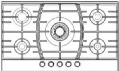
| Model idencaon | AS5324X01 | ||
| Type of hob | GAS AND ELECTRIC BUILT-IN HOB | ||
| Symbol | Value | Unit | |
| Number of electric cooking zones and/or areas | 2 | ||
| Heang technology | Solid plates | ||
| For circular electric cooking zones | 14,5 | cm | |
| Energy consumpon per electric cooking zone or area calculated per kg | EC electric cooking | 188.4 | Wh/kg |
| Number of gas red burners | 4 | ||
| Energy eciency per right rear gas burner | EEgas burner | 60,3 | % |
| Energy eciency per le front gas burner | EEgas burner | 58,4 | % |
| Energy eciency per le rear gas burner | EEgas burner | 58,4 | % |
| Energy eciency for the gas hob | EEgas hob | 59 | % |
In order to determine compliance with the eco-design requirements, the measurement methods and calculations of the following standards were applied:
EN 30-2-1
Model:
CS 5222 - CS 5224- CS 5224 W- CS 5289 - CS 5249 - CS 5249 W CS 5246 - CS 5223 - CS 5223 W - CS 5236- CS 5236W - CS 5253 CS 5307- CS 5310 - CS 5308- CS 5311- AS 5241- AS 5215 AS 5242 - AS 5216 - AS 5271 - AS 5274 - AS 5277- AS 5280 CS 5309 - CS 5243 - CS 5243 W - CS 5217 - CS 5217 W - CS 5218 CS 5218 W- CS 5234 - CS 5234 W - CS 5303 - CS 5306 - AS 5233 AS 5238 - AS 5239 - AS 5275 - AS 5286 - AS 5214- AS 5276 CS 5244 - AS 5278 - AS 5283- AS 5287 - CS 5284 - AS 5240 AS 5279 - CS 5264 - CS 5263 - CS 5244 W - CS5243B01 AS5323X01 - AS5324X01
natural_image
Simple geometric symbol with a circle and two crosshairs inside a rounded square (no text or labels)AR
دليل استخدام المو
SILVERLINE®
العزيز عميلنا
natural_image
Abstract circular arrow diagram with no text or symbolsnatural_image
Simple line drawing of a trash bin with crossed lines indicating no waste or discharge (no text or symbols)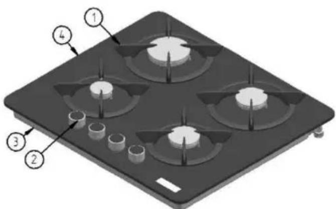

ات حاملای.
تحكم أزرا.
لموقد قاعك.
لfolاذ حقل4.
natural_image
Pure electrical circuit lines without any symbolsAS 5214
natural_image
Technical diagram of a gas stove with circular vented fans and heating elements (no text or labels)AS 5215
natural_image
Grid pattern with concentric circles and a central star, no text or symbols presentAS 5216
natural_image
Line drawing of a four-g Windowed kitchen appliance with control knobs (no text or symbols)AS 5233
natural_image
Pure electrical circuit lines without any symbolsAS 5238
natural_image
Pure electrical circuit lines without any symbolsAS 5239
natural_image
Technical diagram showing three grid panels with circular features and a central circular component, no text or symbols present.AS 5271
natural_image
Simple line drawing of a 3x4 grid with circular patterns and a row of five circles below (no text or symbols)AS 5240
natural_image
Four circular mechanical components with cross-shaped cutouts, arranged in a 2x2 grid (no text or symbols)CS 5217-CS 5217 W
natural_image
Line drawing of a four-gas stove with circular vented lights and a central rotary knob (no text or symbols)AS 5241
natural_image
Grid pattern with concentric circles and control buttons at the bottom (no text or symbols)AS 5242
natural_image
Technical diagram of a three-position gas stove with circular vented lights and grid patterns (no text or labels)AS 5274
natural_image
Line drawing of a four-gas stove with heat sinks and ovens (no text or symbols)AS 5275
natural_image
Line drawing of a gas stove with six panes and a central cylinder (no text or symbols)AS 5277

natural_image
Line drawing of a four-gas stove with four panes and control knobs (no text or symbols)AS 5276
natural_image
Line drawing of a four-gas stove with four panes and control knobs (no text or symbols)AS 6279
natural_image
Line drawing of a four-gas stove with six fans and a central vent (no text or symbols)AS 5280
natural_image
Simple line drawing of a three-tiered gas stove with circular vent grilles and two side outlets (no text or symbols)AS 5283
natural_image
Line drawing of a four-gas stove with four fans and three ovens (no text or symbols)AS 5286
natural_image
Line drawing of a double-gas stove with two circular vented gauges and three switches at the bottom (no text or symbols)AS 5287
natural_image
Pure electrical circuit lines without any symbolsCS 5234-CS 5234W
natural_image
Pure electrical circuit lines without any symbolsCS 5218-CS 5218 W
natural_image
Pure electrical circuit lines without any symbolsCS 5222
natural_image
Technical line drawing of a gas stove fan with four circular vented lights and a central hub (no text or symbols)CS 5223-CS 5223 W
natural_image
Symmetrical diagram with four circular components and a row of small circular elements below (no text or labels)CS 5246
natural_image
Technical line drawing of a mechanical component with concentric circles and mounting holes (no text or symbols)CS 5224-CS 5224 W
natural_image
Two identical circular diagrams with crosshair patterns, no text or symbols presentCS 5263
natural_image
Pure electrical circuit lines without any symbolsCS 5236-CS 5236 W
natural_image
Four circular target-like symbols with crosshair patterns, arranged in a 2x2 grid (no text or labels)CS 5243-CS 5243 W
natural_image
Four circular mechanical components with cross-sectional views, no text or symbols presentCS 5244-CS 5244 W
natural_image
Pure technical diagram of a mechanical component with symmetrical circular features and mounting holes (no text or symbols)CS 5249-CS 5249 W
natural_image
Pure diagram of six circular components with crosshair indicators, no text or symbols presentCS 5253
natural_image
Simple line drawing of a circular mechanical component with cross-shaped cutouts and concentric rings (no text or symbols)CS 5264
natural_image
Line drawing of a double-gas stove with two circular vent grilles and three side gauges (no text or symbols)CS 5284
natural_image
Line drawing of a four-g Windowed kitchen appliance with circular vent and control knobs (no text or symbols)AS 5278
natural_image
Pure electrical circuit lines without any symbolsCS 5306
natural_image
Technical line drawing of a gas stove fan with circular components and mounting holes (no text or symbols)CS 5307
natural_image
Technical line drawing of a gas stove or gas stove with four circular components and grid lines (no text or symbols)CS 5308
natural_image
Pure electrical circuit lines without any symbolsCS 5309
natural_image
Technical line drawing of a three-panel electrical cabinet or fan layout (no text or symbols)AS5323X01
natural_image
Pure electrical circuit lines without any symbolsCS 5289
natural_image
Pure electrical circuit lines without any symbolsCS 5303
natural_image
Pure electrical circuit lines without any symbolsCS 5310
natural_image
Pure electrical circuit lines without any symbolsCS 5311
natural_image
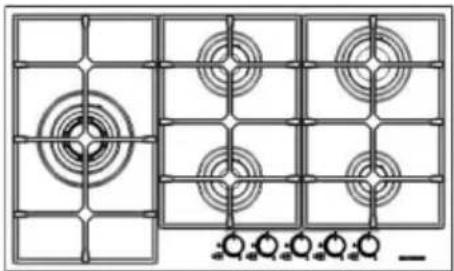
Technical diagram of a four-panel air vent with circular components and radial gauges (no text or labels)AS5324X01
natural_image
Four identical circular fan symbols with crosshair patterns, arranged in a 2x2 grid above four circles (no text or labels)CS5243B01
المواقد استخدام همع
عيون الغاز
natural_image
Four identical diagrams of a circular object with orbiting arcs and marked points, no text or symbols present.natural_image
Two circular diagrams with arrows and dots, no text or symbols present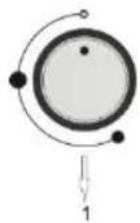
natural_image
3D rendering of a mechanical gear assembly with no visible text or symbols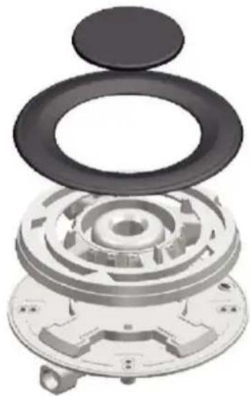
natural_image
Exploded view diagram of a mechanical assembly with concentric gears and a circular housing (no text or symbols)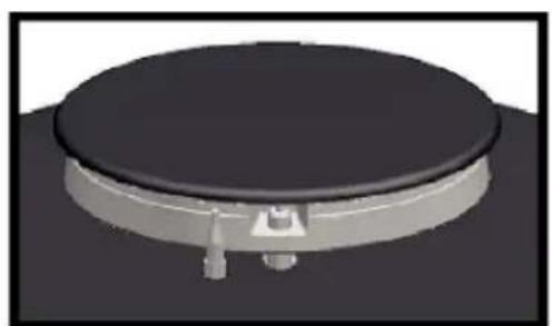
natural_image
3D rendering of a circular mechanical component with a central hub and mounting base (no text or symbols visible)صحيح
natural_image
3D rendered diagram of a circular mechanical component with intersecting diagonal lines (no text or symbols)خطاً
.1 شكل
.2 شكل
natural_image
Two identical 3D-rendered cooking pots on a black stove, one crossed by a diagonal line (no text or symbols)natural_image
Illustration of two cooking pots on a stove with steam rising (no text or symbols)natural_image
Two white cooking pots on a stove, one crossed with black lines (no text or symbols)natural_image
Two identical 3D-rendered cooking pots on a stovetop, one crossed out by a diagonal line (no text or symbols)لمngx copodococococococococococococococococococococococococococococococococococococococococococococococococococococococococococococococococococococococococococococococococococococococococococococococococococococOCOCOCOCOCOCOCOCOCOCOCOCOCOCOCOCOCOCOCOCOCOCOCOCOCOCOCOCOCOCOCOCOCOCOCOCOCOCOCOCOCOCOCOCOCOCOCOCOCOCOCOCOCOCOCOCOCOCOCOCOCOCOCOCOCOCOCOCOCOCOCOCOCOCOCOCOCOCOCOCOCOCOCOCOCOCOCOCOCOCOCOCOCOCOCOCOCOCOCOCO
natural_image
Diagram of a device with circular components and upward arrows, labeled 'FIGURE 1.' (no text or symbols on diagram itself)1 shock
natural_image
Technical line drawing of a four-positioned industrial machine with a magnified inset showing internal components (no text or symbols)2 شكل
natural_image
Hand holding a tool with a circular base, no text or symbols visiblenatural_image
3D mechanical assembly diagram showing internal components and labeled parts (no text or symbols present)natural_image
Simple geometric symbol with a circle and two crosshairs inside a rounded square (no text or labels)
PRODUCT FICHE ....40
natural_image
Abstract circular arrow diagram with no text or symbolsnatural_image
Symbol of a trash bin crossed with diagonal lines, no text or numbers present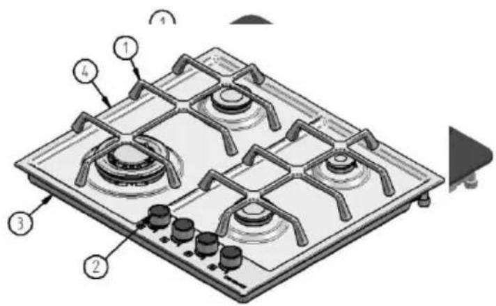
natural_image
Pure electrical circuit lines without any symbolsAS 5214
natural_image
Pure electrical circuit lines without any symbolsAS 5215
natural_image
Grid pattern with concentric circles and a central circle, no text or symbols presentAS 5216

UTILISATION DES PLAQUES DE CUISSON
BRULEURS A GAZ
natural_image
Three circular diagrams with arrows indicating direction, no text or symbols presentnatural_image
3D rendering of a mechanical gear assembly with no visible text or symbols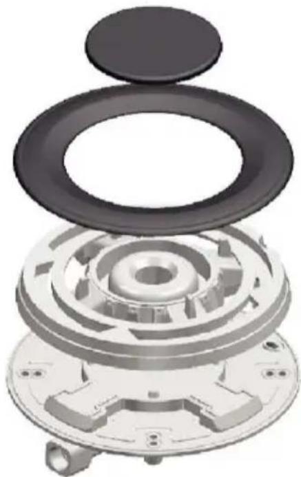
natural_image
3D rendered mechanical assembly showing layered components with no visible text or symbols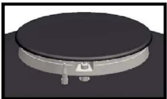
natural_image
3D rendering of a circular mechanical component with a central hub and mounting bracket (no text or symbols visible)JUSTE
natural_image
3D rendering of a circular mechanical component with intersecting diagonal lines (no text or symbols)FAUX
Image 1.
Image 2.
natural_image
Diagram of a planetary orbit with concentric circles and marked points (no text or labels)natural_image
Two identical 3D-rendered cooking pots on a black stove, one crossed by a diagonal line (no text or symbols)natural_image
Illustration of two cooking pots on a stove with crossed lines indicating heating (no text or symbols)natural_image
Two identical 3D-rendered cooking pots on a stove, one crossed with black lines (no text or symbols)natural_image
Two identical 3D-rendered cooking pots on a stovetop with crossed x-line marks, no text or symbols present.natural_image
Metal plate with rectangular cutouts and mounting holes, showing diagonal black lines indicating alignment or measurement (no text or symbols)Image 8.
CONNEXION ELECTRIQUE
natural_image
3D technical diagram of a mechanical assembly with labeled parts (no readable text or symbols)Üretici Firma / Manufacturer / Fabricant


- DEĞERLİ MÜŞTERİMİZ,
- OCAKLARIN KULLANIMI
- GAZ BEKLERİ
- Our Valued Customer,
- CONTENTS
- GENERAL SAFETY WARNINGS
- SAFETY FOR CHILDREN
- SAFETY OF THE GAS
- Things to be done when gas smells
- Packaging
- Disposal of the old equipments
- USAGE OF HOBS
- GAS BURNERS
- FIRING OF BURNER
- MODELS EQUIPPED WITH LIGHTER SWITCH (Automatic ignition)
- Operation of the burners and power levels
- WARNING;
- Closing the burners
- Flame Failure Device (FFD)
- UTILIZATION OF HOT PLATE
- Warnings
- Usage
- Turning on the Plate:
- Suggestions
- Using Right Burner
- Usage of grills and recommendations
- INSTALLATION OF THE UNIT
- PRE-INSTALLATION WARNINGS
- Read the following instructions to fix the hob on the counter:
- INSTALLATION INFORMATION ON THE UNIT
- Release of Burnt Gases
- Installation of the Hob on the Counter
- ELECTRIC CONNECTION
- GAS CONNECTION
- ADJUSTMENT OF HOB PER GAS TYPES
- HOB'S ENERGY EFFICIENCY
- CLEANING AND MAINTENANCE
- Please comply with the following rules before cleaning and maintenance.
- Enamel Parts
- Pan Supports
- Burner
- PRODUCT FICHE
- Model:
- .1 شكل
- UTILISATION DES PLAQUES DE CUISSON
- BRULEURS A GAZ
- CONNEXION ELECTRIQUE
- Üretici Firma / Manufacturer / Fabricant
Brand : SILVERLINE
Model : AS 5324 X01
Category : Cooker