
SUB 2 - Subwoofer Paradigm - Free user manual and instructions
Find the device manual for free SUB 2 Paradigm in PDF.

| Product Type | Sealed Active Subwoofer |
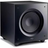
| Brand and Model | Paradigm Reference Signature SUB 2 |
| Drivers | 6 x 10" (254 mm) mineral-loaded polypropylene cones, 3" (76 mm) 10-layer aluminum voice coil |
| Amplifier | Ultra-Class-D "Kilomax" with Power Factor Correction, 9000 W dynamic peak, 4500 W continuous RMS (on 240 V circuit) |
| Frequency Response | 7 Hz (DIN) to 150 Hz |
| Crossover Frequency | Variable 35 Hz – 150 Hz, with bypass |
| Phase Alignment | Variable 0° – 180° |
| Inputs | Stereo/mono RCA (LFE) and balanced XLR, USB for PBK |
| Power Supply | Universal 108 – 265 V AC, 50/60 Hz (120 V and 240 V cables included) |
| Power Consumption | Up to 4500 W RMS (240 V), very low standby |
| Dimensions (H x W x D) | Approximately 38 x 45 x 45 cm (not specified exactly, hexagonal cabinet) |
| Weight | Approximately 50 kg (estimated for 6 x 10" drivers and powerful amplifier) |
| Finish | Cherry or piano black (high-quality furniture finish) |
| Special Features | Vibration-canceling architecture, Perfect Bass Kit (PBK) included, auto power on/standby, 12 V trigger |
| Maintenance and Cleaning | Clean with a soft, damp cloth; do not use abrasive detergents. Avoid any liquid contact. |
| Safety | Do not open the cabinet; refer all servicing to qualified personnel. Protect from moisture and rain. |
| Spare Parts and Repairability | Contact an authorized Paradigm dealer or technical support. Limited 3-year warranty. |
| General Information | Manufacturer: Paradigm Electronics Inc. (Canada). Designed and manufactured in North America. Compatible with Perfect Bass Kit (PBK). |
Frequently Asked Questions - SUB 2 Paradigm
User questions about SUB 2 Paradigm
0 question about this device. Answer the ones you know or ask your own.
Ask a new question about this device
Download the instructions for your Subwoofer in PDF format for free! Find your manual SUB 2 - Paradigm and take your electronic device back in hand. On this page are published all the documents necessary for the use of your device. SUB 2 by Paradigm.
USER MANUAL SUB 2 Paradigm
In accordance with the European Union WEEE Waste Electrical and Electronic Equipment directive effective August 13, 2005, we would like to notify you that this product may contain regulated materials which, upon disposal, according to the WEEE directive, require special reuse and recycling processing. For this reason Paradigm Electronics Inc. (manufacturers of Paradigmspeakers and AnthemElectronics) has arranged with our distributors in European Union member nations to collect and recycle this product at no cost to you. To find your local distributor please contact the dealer from whom you purchased this product or go to our website at www.paradigm.com.
Please note that the product only falls under the WEEE directive. When disposing of packaging and other shipping material we encourage you to recycle through the normal channels.

TABLE OF CONTENTS

1
Introduction

3
The Design & Technology Behind Your New Subwoofer

7
Safety Precautions

8
Important Safety Instructions

11
Placement & Connection SUB 1 & SUB 2 (pictorial)

14
Your New Subwoofer

14
Absolute Power

15
Room Acoustics

16
Room Placement
Paradigm Perfect Bass Kit

22
Connection & Control

24
Fine Tuning

25
Universal Input
Power in SUB 2

27
Connecting SUB 2 to a 240-Volt Line

29
Power Factor Correction in SUB 2

31
Limited Warranty

32
Technical Specifications

34
Notes

PARADIGM® REFERENCE SIGNATURE SUB 1 AND SUB 2
Thank you for choosing the truly mind blowing Paradigm® Reference Signature SUB 1 and SUB 2 and congratulations! You are now the proud owner of the world's finest subwoofoers, designed, engineered and manufactured in North America. You are about to experience the stunning difference your new state-of-the-art high-end subwoofer will make in your music and home theater system.
Paradigm subwooers are internationally recognized for their exceptional sound. In fact, Paradigm is the only speaker company to be rated #1* year after year. Quite simply, ours are the best sounding subwooers in the world. Extensive listener preference tests conducted by the National Research Council (NRC) gave our design engineers a firm understanding of how we hear speakers, including subwooers, and clearly established the design parameters most critical to good sound. Using the NRC findings along with measurement-based analysis done in our anechoic chamber and double-blind testing carried out in our controlled listening rooms, our engineers work to constantly improve and refine subwoofer performance in all areas. We consider these subwooers our finest accomplishment to date.
Signature. Love to Listen.
*Rated #1 Best Price/Value. Inside Track Annual Dealer Survey. An annual independent nationwide survey of consumer electronics specialist retailers and custom installers.
PARADIGM® REFERENCE SIGNATURE SUB 1 AND SUB 2

Your new subwoofer is a supremely powerful, accurate, as well as physically attractive state-of-the-art six-sided sealed system that boasts:
- A Compact Hexagonal Form Factor;
- Vibration-Canceling Design Architecture — set a martini on top of the cabinet while the subs are playing and barely a ripple is noticeable;
- Six Cutting-Edge High-Excursion Bass Drivers with advanced mineral-filled polypropylene cones and distortion-reducing surrounds;
- Our Own Cutting-Edge Ultra-Class-D™ 'Kilomax' Amplifier Platform with Universal Input Power and Power Factor Correction (SUB 2);
- 2 Cutting-Edge Ultra-Class-D Amplifiers (SUB 1);
- Our Own Digital Signal Processing Design;
- A Comprehensive Range of Input and Control Facilities;
- High-Quality Furniture-Grade Finish ... a powerful subwoofer or high-end coffee table? Judging by appearances, it's difficult to say.
The Paradigm Perfect Bass KitTM
Even when the finest subwoofoers are perfectly spaced and positioned, the room itself can still have a dramatic impact on performance. Room dimensions, dead spots, archways, even furniture can turn the room into an additional instrument playing alongside musicians or movie scores with unwanted coloration and resonance. Bass can sound boomy with poor definition. You have the perfect subwoofer but in a less than perfect room! The solution is
included with your new subwoofer ... Paradigm's critically acclaimed Perfect Bass Kit (PBK). Based on research conducted by the National Research Council, PBK analyzes the subwoofer's response in your room, then sets about perfecting that response through scientific calculation! And it's receiving rave reviews ...
"...audibly better bass through science... Does it really work? You bet it does. Several noteworthy features of the software are its ability to correct multiple peaks and/or troughs in the subwoofer/room bass response curve, to identify and address potential standing wave problems, to calculate a solution that helps optimize bass response across multiple listening locations, and that, purists please take note, affects only the subwoofer—not the other speakers...I did some listening tests with the Paradigm sub before using the PBK kit and then afterwards, and I can vouch for the fact that the PBK equalized sub sounded much tighter, more neutrally voice, and much better defined." - AV Guide on PBK
Your Signature subwoofer will provide you with stunning high-end sound and unparalleled listening pleasure for many years. To achieve all of the exceptional sound it is capable of providing requires care in placement, installation and operation. Please take the time to read this manual and follow all instructions. Or visit our website at www.paradigm.com for more information. If you have additional questions, contact your Authorized Paradigm® Reference Dealer or visit the Q&A page in the Tech Support section of our website.

THE DESIGN & TECHNOLOGY BEHIND
YOUR NEW SUBWOOFER

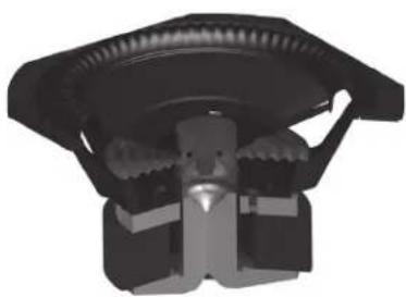
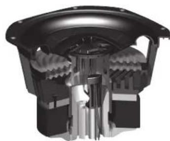
Vibration-Canceling Design Architecture
Six identical, perfectly-balanced cutting-edge drivers radially aligned (two on each side) inside the cabinet. As opposing forces of equal magnitude, the powerful vibration-reaction forces (see arrows) effectively cancel each other out. Place a martini glass on top of SUB 1 or SUB 2 and barely a ripple disturbs the contents while the subwoofer is playing.
THE DESIGN & TECHNOLOGY BEHIND
YOUR NEW SUBWOOFER (continued)

SIGNATURE SUB 1
- Six 8'' (203 mm) Cutting-Edge Mineral-Filled Polypropylene Cones
Overmolded NLC Non-Limiting Corrugated TPE Surrounds with NomexCloth Spiders
1-1/2-Inch (38 mm) 4-Layer Long-Throw Aluminum Voice Coil
AVS Airflow Ventilation System Cooling
9.2 lb (4.16 kg) Computer-Optimized Ceramic (Hard Ferrite) Magnet/Motor Structure - Removable Grilles
SIGNATURE SUB 2
- Six 10^ (254 mm) Cutting-Edge Mineral-Filled Polypropylene Cones
RCR Resonance Control Ribbing with Dual Nomex Cloth Spiders
3-Inch (76 mm) 10-Layer Long-Throw Aluminum Voice Coils
AVS Airflow Ventilation System Cooling - 25.2 lb (10.5 kg) Computer-Optimized Ceramic (Hard Ferrite) Magnet/Motor Structure
- For safety, grilles are non-removable due to the incredibly high power and tremendous output


Paradigm Perfect Basis Kr^TM Interface on rear panel
SIGNATURE SUB 1
BIG POWER. Compact Package. Two Cutting-Edge Ultra-Class-D™ Amplifiers:
3,400 Watts Dynamic Peak Power
1,700 Watts RMS Continuous Power (850 watts each amp)
- Digital Signal Processing Design (DSP). Sophisticated mathematical algorithms 'shape' frequency response ensuring accurate, consistent and musical bass without distortion even when the subs are playing at the loudest level
- 5 / 8" (16 mm) Ultra-Rigid Aluminum Amplifier Panel provides revolutionary heatsinking and mechanical rigidity
THE DESIGN & TECHNOLOGY BEHIND
YOUR NEW SUBWOOFER (continued)
SIGNATURE SUB 2
Cutting-Edge 'Kilomax' Amplifier Platform with Universal Input Power and Power Factor Correction
9,000 Watts Dynamic Peak Power
4,500 Watts RMS Continuous Power when connected to a 240-volt line (more information is provided in the section 'Universal Input Power in SUB 2')
Digital Signal Processing Design (DSP) (see SUB 1, previously)
Power Factor Correction allows the maximum amount of power (95%) to be drawn with far less noise on the line (more information is provided in the section 'Power Factor Correction in SUB 2')
- 5/8 (16 mm) Ultra-Rigid Aluminum Amplifier Panel provides revolutionary heatsinking and mechanical rigidity


Aluminum Printed Circuit Board: 1/8^ (3.2 mm) thickness

Paradigm Perfect Bass Kilt® inter-face on rear panel

SAFETYPRECAUTIONS
READ THIS SECTION CAREFULLY BEFORE PROCEEDING!

WARNING
RISK OF ELECTRIC SHOCK DO NOT OPEN

WARNING: TO REDUCE THE RISK OF ELECTRIC SHOCK, DO NOT REMOVE COVER (OR BACK). NO USER-SERVICEABLE PARTS INSIDE. REFER SERVICING TO QUALIFIED SERVICE PERSONNEL.

The lightning flash with arrowpoint within an equilateral triangle warns of the presence of uninsulated "dangerous voltage" within the product's enclosure that may be of sufficient magnitude to constitute a risk of electric shock to persons.

The exclamation point within an equilateral triangle warns users of the presence of important operating and maintenance (servicing) instructions in the literature accompanying the appliance.
WARNING: TO REDUCE THE RISK OF FIRE OR ELECTRIC SHOCK, DO NOT EXPOSE THIS APPARATUS TO RAIN OR MOISTURE, AND OBJECTS FILLED WITH LIQUIDS, SUCH AS VASES, SHOULD NOT BE PLACED ON THIS APPARATUS.
CAUTION: TO PREVENT ELECTRIC SHOCK, MATCH WIDE BLADE OF PLUG TO WIDE SLOT, FULLY INSERT.
CAUTION: FOR CONTINUED PROTECTION AGAINST RISK OF FIRE, REPLACE THE FUSE ONLY WITH THE SAME AMPERAGE AND VOLTAGE TYPE. REFER REPLACEMENT TO QUALIFIED SERVICE PERSONNEL.
WARNING: UNIT MAY BECOME HOT. ALWAYS PROVIDE ADEQUATE VENTILATION TO ALLOW FOR COOLING. DO NOT PLACE NEAR A HEAT SOURCE, OR IN SPACES THAT CAN RESTRICT VENTILATION.
IMPORTANT SAFETY INSTRUCTIONS

- Read these instructions.
- Keep these instructions.
- Heed all warnings.
- Follow all instructions.
- Do not use this apparatus near water.
- Clean only with dry a cloth.
- Do not block any ventilation openings. Install in accordance with the manufacturer's instructions.
-
Do not install near any heat sources such as radiators, heat registers, stoves, or other apparatus (including amplifiers) that produce heat.
-
Do not defeat the safety purpose of the polarized or grounding-type plug. A polarized plug has two blades with one wider than the other. A grounding type plug has two blades and a third grounding prong. The wide blade or the third prong are provided for your safety. If the provided plug does not fit into your outlet, consult an electrician for replacement of the obsolete outlet.
- Protect the power cord from being walked on or pinched, particularly at plugs, convenience receptacles and the point where they exit from the apparatus.
- Only use attachments/accessories specified by the manufacturer.
- Use cart with the cart, stand, tripod, bracket, or cart is specified by the manufacturer or sold with the cart. When a cart is used, use caution when moving the cart/ apparatus combination, to avoid injury from tip-over.

- Unplug this apparatus during lightning storms or when unused for long periods of time.
- Refer all servicing to qualified service personnel. Servicing is required when the apparatus has been damaged in any way, such as power-supply cord or plug is damaged, liquid has been spilled or objects have fallen into the apparatus, the apparatus has been exposed to rain or moisture, does not operate normally, or has been dropped.
-
Use the mains plug to disconnect the apparatus from the mains or "TO COMPLETELY DISCONNECT THIS APPARATUS FROM THE AC MAINS, DISCONNECT THE POWER SUPPLY CORD PLUG FROM THE AC RECEPTACLE.
-
"WARNING - TO REDUCE THE RISK OF FIRE OR ELECTRIC - SHOCK, DO NOT EXPOSE THIS APPARATUS TO RAIN OR MOISTURE"
- "DO NOT EXPOSE THIS EQUIPMENT TO DRIPPING OR SPLASHING AND ENSURE THAT NO OBJECTS FILLED WITH LIQUIDS, SUCH AS VASES, ARE PLACED ON THE EQUIPMENT."
- "THE MAINS PLUG OF THE POWER SUPPLY CORD SHALL REMAIN READILY OPERABLE."


PLACEMENT & CONNECTION SUB 1 & SUB 2
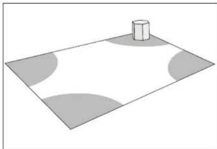
Fig. 1a
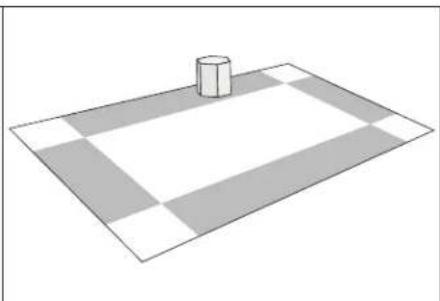
Fig. 1b Fig. 2
PLACEMENT & CONNECTION SUB 1 & SUB 2 (continued)

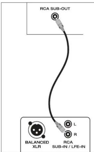
Fig. 3a
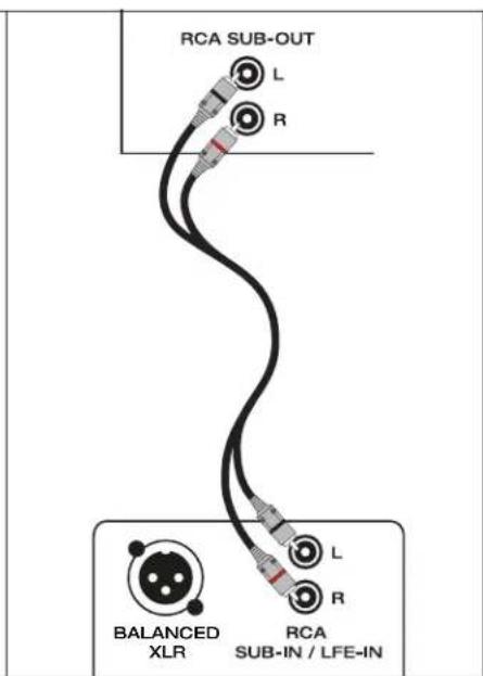
Fig. 3b Fig. 4

YOURNEW SUBWOOFER

Break-In
Although your Paradigm® Reference Signature subwoofer will sound great "out of the carton" it will sound even better when broken in. Allow it to operate for several hours before you begin to listen critically.
Cleaning
Your subwoofer has a durable premium finish. To clean, use a damp soft cloth. Do not use a strong or abrasive cleaner. Avoid getting any part of the subwoofer system wet. Do not place wet objects (drinking glasses, potted plants, etc.) directly on top of your new subwoofer. A coaster must be used every time. If allowed to soak in, even a small amount of water may permanently damage the gorgeous high-end furniture finish.
ABSOLUTE POWER ... IS VERY VERY COOL


The "Watts" (W) rating indicated on the rear panel is the typical power your subwoofer will draw during normal use. However, when producing its maximum power output, the actual wattage draw will vary with the bass content of the program material—more if there is a lot of deep bass, less when there is not as much bass. Connected to a regular 120-volt line SUB 1 and SUB 2 will deliver every ounce of state-of-the-art performance we promise ... and more! However ...

A Note About the Absolutely Insane Power Capabilities of SUB 2
SUB 2 boasts the most powerful amplifier we have ever designed. It boasts a Universal Input Power Feature which allows the subwoofer to operate connected to any line voltage between 108 volts and 265 volts. To get every ounce, and we do mean EVERY ounce, of performance SUB 2 was designed to deliver, aka Maximum RMS Continuous Power, connect SUB 2 to a dedicated 240-volt/15-amp circuit. This type of connection must be done by a certified electrician. Detailed information on this can be found later in this manual in the section 'Universal Input Power in SUB 2.'
For convenience, packed in the carton along with your SUB 2 are two power cords: a 120-volt / 15-amp cord and a 240-volt / 15-amp cord.
You are about to experience the astonishing performance of your state-of-the-art Paradigm® Reference Signature subwoofer. SUB 1 and SUB 2 incorporate groundbreaking technology that has been in the works in Paradigm's Advanced Research Center (PARC) for a number of years. The results set outrageous new standards for deep bass extension, ultra-low distortion and sound power output to provide bass articulation and slam the likes of which have never been heard!
It is important to note however that just as the amount of soft furnishings has a decided impact on mid and high frequencies, those below 150Hz are dramatically affected by the room itself—its size, shape, as well as by physical boundaries throughout the room.
It is helpful to keep the following guidelines in mind when deciding on best subwoofer placement:
Concrete floors and walls tend to aggravate low-frequency standing wave problems and are less preferred;
- Rooms where height, width and length are similar should be avoided as they can exhibit significant low-frequency standing wave problems. This may result in reduced clarity.
If circumstances dictate placement, don't worry, the Paradigm Perfect Bass Kit digital room correction system will tackle even the most challenging problems of the room. More about this in the following section.
ROOM PLACEMENT &
THE PARADIGM PERFECT BASS KIT™

PBK
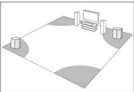
Bass is less and less directional as it goes down in frequency. For best sonic integration, locating your subwoofer between your front speakers or beside one of them and close to the back wall will usually provide the best bass performance. If this location is not possible your subwoofer may be placed anywhere in the room without affecting the stereo image of your front speakers or the soundstage of your multichannel speaker system.
Figure 1a: Corner placement provides the most bass, but sometimes at the expense of accuracy.
Figure 1b: A subwoofer placed near a wall usually provides a good balance of quantity and accuracy.
Although controls are provided to align your subwoofer's output to the other speakers in your system, see "Fine Tuning," on page 24, you have at your disposal the most powerful, accurate and innovative tool in the industry for achieving optimal bass performance in any room situation. The critically acclaimed Paradigm Perfect Bass Kit (PBK) is a true audiophile solution to the problems of the room. It allows you to correct for the effects of room boundaries on the quality of bass. See next page.
THE ADVANTAGES OF USING TWO SUBWOOFERS IN YOUR LISTENING ROOM
What's the only thing better than a single SUB 1 or SUB 2? Two of them! Although a single Paradigm Reference® Signature SUB 1 or SUB 2 provides cutting-edge performance and breathtaking output, the quality (and quantity) of bass can be further improved with the use of two subwoofer. Placing one in the front of the room and the other in the rear of the room (see Fig. 2) usually provides the best bass performance and sonic integration. Begin by placing your subwoofer in these standard positions, then apply the Paradigm Perfect Bass Kit procedure to the first subwoofer, then to the second.

PARADIGM PERFECT BASS KITTM:
A TRUE AUDIOPHILE SOLUTION TO THE PROBLEMS OF THE ROOM
Step-by-step instructions for using the Paradigm Perfect Bass Kit are included in the following section but before you begin, a little about how PBK works on your room and what makes it better than any other digital room correction system in the world:
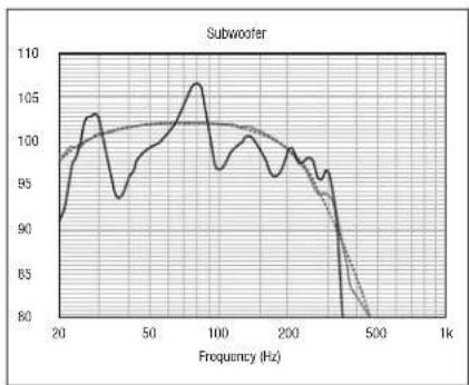
- PBK is a state-of-the-art "bass perfecting" system that analyzes the subwoofer's response in your room, then sets the correct equalization parameters to attain optimal sound. The frequency response of each PBK microphone is measured precisely and the data is used to create the microphone's calibration file included on the PBK software disk. The microphone can only be used with the matching individual calibration file.
- PBK applies Super-Efficient Infinite Impulse Response (IIR) Filters in addition to Paradigm's Custom Filter Topology to minimize delay and reduce processing gain noise. The combination of limiting the widths of our IIR filters and applying our topology means that any artifacts that might have resulted from the filtering process are so small as to be completely inaudible.
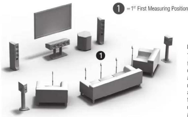
- PBK allows for Multiple Microphone Measurements: Most room equalization methods work from only a single point source, taking one measurement at the primary listening position. PBK provides for multiple
user-selected measurement points (we suggest a minimum of five, but up to ten can be measured), beginning with a measurement at the primary listening position and then moving across the listening area. This process is critical to properly dealing with standing waves and ensuring optimal bass performance throughout the listening area.
- Unlike many "Room EQ" systems, PBK applies Correction to Peaks (modes) and Dips (anti-modes). Tackling both allows us to achieve a far more accurate and natural room response. To limit the demands on the amplifier and maximize signal-to-noise ratio PBK applies appropriate limits to this correction.
- PBK is Ultra-Accurate! The connected PC's 64-bit floating-point processor does the hard work of calculating the correction curves, which greatly minimizes rounding errors of a less sophisticated "calculator".
- It's Easy to Use (we've done the hard work!). Three years of intensive research and development on our part have made it a snap to attain Perfect Bass performance in any room! All that's required is a PC running Windows XP, Vista or Windows 7*, 2 USB ports and the Paradigm Perfect Bass Kit.
NOTE: *As new PC operating systems become available the PBK system will be updated. Go to http://www.paradigm.com/PBK to download the compatible version, following the procedure for 'Installing the Software' on page 19.
ROOM PLACEMENT &
THE PARADIGM PERFECT BASS KIT
(continued)

Your PBK Kit includes:
- Paradigm® Perfect Bass Kit (PBK) software installation CD
- Microphone and microphone clip
- Telescoping stand and base
- Two USB cables: one for microphone, one for subwoofer
Steps to assemble stand and microphone:
- Screw the telescoping stand into the base and tighten securely;
- Position the clip vertically and screw onto the stand, tighten;
- Connect the USB microphone cable to the microphone;
- Slide the microphone into the clip and point microphone straight up (see section 'Positioning the Microphone' for more information).
How does PBK do what it does?
The process starts when a test signal is sent from your computer to the subwoofer and the signal is picked up by the individually calibrated microphone. The system puts the subwoofer through a frequency sweep to highlight problem areas and determine necessary adjustments. It asks you to position the microphone in at least 5 different locations. Configurations are then saved on the connected PC. The optimized solutions are calculated, then uploaded to the subwoofer and the calculated room corrections are put in place.

Getting Started
Begin with the suggested locations for subwoofer placement given at the beginning of this manual then connect your subwoofer following the instructions given in the section entitled "Subwoofer Connection". Once your subwoofer is connected, read the instructions below, then follow the prodedure at right to install Paradigm's Perfect Bass Kit.
Before starting the procedure, note the following:
- PC requirements are Windows XP, Vista or Windows 7* and 2 USB ports. If you are running a newer operating system see note about updating PBK files to match on page 17.
- If you are using a laptop computer, check power settings and battery meter before starting to ensure the procedure will not be interrupted.
Although systems vary, in general, if your home theater receiver/processor also has a Room Correction system, PBK should be set up and running before setting up your system's 'EQ', especially if more than one subwoofer will be in use.
IMPORTANT! Don't stand too close to the microphone or make noise when sweep tones are playing (it would be best to keep younger or talkative family members and even pets out of hearing range). The program rejects continuous background noise (i.e. fans) but will give an error message requiring re-measurement upon sudden noise.
THE PROCEDURE
IMPORTANT! Each time we introduce a new product to work with PBK, the PBK software must be updated. The unique calibration file required to operate your microphone is included on the enclosed CD and will be installed during program installation from the CD. However, there may have been additional software program updates since your CD was published. To achieve optimal performance you must be using the latest software version. Follow the instructions provided below to install the software and then check our website for newer versions.
Install the Software
Insert the PBK installation CD into your computer's CD or DVD drive. Installation instructions will appear on your screen. If your computer does not allow a CD to 'auto-run', double-click on the 'My Computer' icon on your computer desktop and select the CD drive, open it and double-click on setup.exe. The process will install several files into a Paradigm folder on your computer and create shortcuts on your Start Menu.
Confirm Your Software Version Once the Software is Installed
a) End the program and reopen it using the shortcut in the Start Menu;
b) A 'Welcome' window will appear on your screen. Click 'Open a previous session' and then click 'OK';
ROOM PLACEMENT &
THE PARADIGM PERFECT BASS KIT™ (continued)
c) A new search window will appear. Click 'Cancel' in the bottom right corner to bring up a measurement window;
d) On the menu bar at the top of the new window go to 'Help', then 'About.' The version number will be displayed. Make a note of it;
e) Once installation is complete, delete zip file and extracted folder.
Check Online for the Latest Version of PBK Software
Go to http://www.paradigm.com/PBK and check under 'Latest Software' section to see if a newer version of the software is posted. If your version is up-to-date, simply restart the program and run PBK.
To update the version do the following:
a) Make sure the program is closed on your computer before downloading new version;
b) Download the latest version to your computer desktop;
c) Right-click on the downloaded .zip file and extract to desktop;
d) Open the extracted folder and double-click on 'Setup'. Software installation instructions will appear on your screen. Follow them;
e) Once installation is complete, delete file and folder;
f) Go to Start Menu and run PBK.

Positioning the Microphone
IMPORTANT! During the measurement process, the mic must point toward the ceiling, positioned at ear level when you are seated.
- Position microphone on or near the first position (see diagram, pg. 18). Remove cushions from seating, if necessary, to attain correct height. To adjust the height of the telescoping stand, loosen the large black clamp in the middle of the stand by rotating it counter-clockwise; retighten once desired height has been achieved.
Five listening positions are normally measured but this number can be increased to ten positions (see diagram, pg. 18)—the first position must be at or just in front of the central seating position. Positions 2 and 3 should be symmetric to the left and right of the center line. The same applies to the remaining positions.
IMPORTANT: Even if your room has less than five seating positions, to ensure optimal sound, measurements must be taken from five different listening positions. Each position should be at least 2 feet (60 cm) apart. - Set the microphone in the first position;
- Before starting to measure, set the subwoofer's Gain control to its center detent position; set Cut-Off Frequency to Bypass; and set Phase control to '0'. After running PBK, these controls can be adjusted as necessary as you complete the setup of your system. See section 'Fine Tuning.'

Sample PBK Analysis/Correction
- Run Paradigm Perfect Bass Kit (PerfectBassKit.exe) by selecting it from the Start Menu. The program will guide you through the steps and at the conclusion, will automatically load the correction data into your subwoofer. The entire measurement process takes about 5 minutes;
- Once the PBK program is finished you can disconnect the PC from the microphone and subwoofer;
- If position of subwoofer or listening positions change you will have to re-measure.
CONNECTION & CONTROL


SAFETY PRECAUTION: Before proceeding with this section, be sure to read and follow all safety precaution notices and warnings at the beginning of this manual.

Turn all components OFF before connecting the subwoofer.
NOTE: We recommend the use of high-quality cables and connectors. (See your Dealer for more information.)
INPUT FACILITIES
Low-Level Input 2 RCA Connection Options (Figs. 3a, 3b)
- Mono Input (Left, Right, or Sub-Out) connects from the RCA (S/E) Sub / LFE-Output of your Preamplifier/Processor, A/V Receiver or other suitable low-level source (Fig. 3a).
- Stereo Input (Left & Right) connects from the Stereo Preamplifier, Stereo Receiver or other suitable low-level stereo source (Fig. 3b).
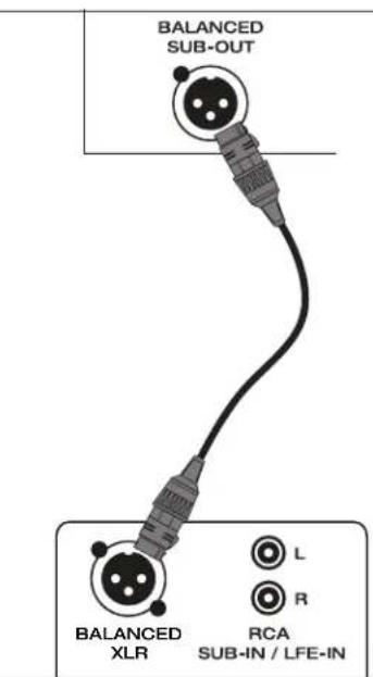
Low-Level Input—Balanced XLR (Fig. 4)
Connects from the Balanced XLR Sub/LFE-Output of your Preamplifier / Processor, A/V Receiver or other suitable low-level source. This input provides the lowest noise and distortion possible. It is particularly important for long cable runs where noise and distortion could degrade performance.

CONTROL FACILITIES
Take the time to read through the following descriptions and become familiar with them before you begin to fine tune your new system.
Auto-On/Standby
Eliminates the need for a manually operated power switch. Turns the subwoofer on when it senses an input signal. If no input signal is sensed after a period of time, the subwoofer will enter standby mode, drawing a very small amount of power. Standby mode allows the subwoofer to switch on quickly when an input signal is present. Note: while is standby mode, the rear panel may be warm to the touch. This is a normal part of the subwoofer operation.
Trigger-On/Off
Allows the subwoofer's power on/off to be controlled by components that have trigger outputs (Preamp/Processor or A/V Receiver, etc.).
Subwoofer Level
Balances the subwoofer's output level with the other speakers in your system. Once set, to make on-the-fly changes for particular program material or personal taste, use your Processor or AV Receiver's subwoofer level control.
Subwoofer Cut-Off and Bypass Option
Controls the subwoofer's upper-frequency cut-off. This can be set to match the low-frequency roll-off characteristics of your system's speakers. For example:
If your speakers play to approximately 80Hz you can set the subwoofer cut-off frequency to approximately 80Hz .
Bypass option allows you to bypass the subwoofer's built-in cut-off control to let your preamp/processor's or receiver's internal bass management system provide the crossover function.
Phase Alignment
Depending on where the subwoofer is placed in your room, there may be bass frequency cancellation. This can occur because your subwoofer and front speakers are out-of-phase—they work against each other through their frequency overlap region. Bass is then reduced and may even sound disjointed. This control accurately synchronizes your subwoofer and front speakers through their bass frequency overlap region.
THE USB PORT / PBK INTERFACE
Allows for:
- Connection of Paradigm's Perfect Bass Kit (PBK) (for more information see the preceding section);
Possible future upgrades to the software installed in your subwoofer.
FINE TUNING

Once you have your speakers positioned in the room and have set speaker distances and speaker level calibration with your Processor or A/V Receiver (if applicable), it's time for a little fine tuning.
When fine tuning your subwoofer to best integrate with the rest of your system use music and video soundtracks that you know well. They should contain selections with extended bass that is continuous and repetitive.
Assess subwoofer bass output for best blend with your main speakers. It should not be overbearing or draw attention to itself, nor should it be thin and difficult to hear. It should add 'weight' and 'punch' to the overall sound and keep pace with your main speakers.
If you are using a receiver, preamplifier or preamp/processor with tone controls, set them to flat (i.e. '0') and switch loudness controls off.
Some subwoofer locations may result in bass frequency cancellations. If bass sounds dislocated or weak, adjust the phase according to the Phase Alignment Control instructions that follow below.
SETTING SUBWOOFER CONTROLS
- Turn the Subwoofer Level control completely counter-clockwise to its minimum.
- Turn the Subwoofer Cut-off Frequency control to its highest frequency (i.e. 150 Hz).
-
Turn the Phase Alignment control to 0^ completely counter-clockwise.
-
Listen to a bass music or video selection while seated in your primary listening area and have an assistant turn up the Subwoofer Level control until the subwoofer can be clearly heard.
- Have an assistant slowly rotate the Phase Alignment control until you hear the most bass. Your subwoofer and front speakers are now in phase. Do not change phase alignment again unless you move subwoofer or front speakers to a different location in your room.
- Again, turn the Subwoofer Level control completely counter-clockwise to its minimum.
- Tum the Subwoofer Cut-off Frequency control to its lowest frequency (i.e. 50 Hz).
- Slowly rotate the Subwoofer Level control until you match the subwoofer's volume with the volume of your front speakers. Bass should be clearly audible, but not intrusive.
NOTE: If using an A/V receiver or processor to control crossover setting, skip the next step and set the subwoofer cut-off frequency control to 'Bypass'.
- Slowly rotate the Subwoofer Cut-off Frequency control until you hear the best subwoofer/front speaker blend. If the sound is too thin you have not set the frequency high enough; if the sound becomes boomy you have set the frequency too high. Adjust until you find the most natural bass balance.
The Universal Input Power feature in SUB 2 allows the subwoofer to operate connected to any line voltage between 108 volts and 265 volts. However, in order to achieve maximum continuous performance, SUB 2 must be connected to a dedicated 240-volt line.
The SUB 2's amplifier can operate on a 120-volt or 240-volt line without requiring modifications to the amplifier or changing an internal switch. Residential 120V circuits are almost always 15A or 20A. Connected to a traditional 120-volt circuit at 15A the SUB 2's amplifier can deliver a whopping 3,000 watts at the voice coil's minimum impedance for several seconds. After that, Paradigm's own Digital Signal Processing (DSP) design lowers the output so that a 15A breaker does not trip.
Connected to a dedicated 240-volt circuit ranging between 208 volts and 240 volts, the SUB 2's amplifier is capable of delivering a frankenstein 4,500 watts of Continuous RMS Power. Talk about bringing your music and movies to life!
It's not so much a power difference, it is simply that a 240-volt line allows for full power all of the time.


CONNECTING SUB 2 TO A 240-VOLT LINE
Q. How do I connect the SUB 2 to a 240-volt line? Does my Dealer need to pre-wire a 240-volt outlet in my listening room to ensure the highest possible performance?
A. In addition to a 15-amp 120-volt cord we include a 15-amp 240-volt IEC connector/cord with each SUB 2. On our cord, the female end looks normal, the male end has the blades turned 90 degrees to flat. These cords can also be bought or made. Existing outlets may be converted as follows:
The following information is included as an FY ONLY: This work should be completed by a qualified electrician only.

IMPORTANT: This procedure is NOT to be used with "Edison" type circuits (i.e. where a red and black pair of circuit wires feeding outlets share a single white neutral.) Check inside the circuit breaker panel to verify the circuit type. Also check to see that only a black (or other colored wire) and white wire are present feeding the outlet to be changed. A green or bare wire should also be present for proper grounding. Presence of another colored wire (often red) run with a black and a white wire generally indicates an Edison Circuit. However, if there is one white wire for each line conductor in the run between the breaker panel and the plug, this is not an Edison circuit and it is then okay to use the following procedure:
- Turn power OFF at breaker box for selected outlet;
- Under ideal conditions, one would select an existing dedicated outlet fed from a single circuit breaker. There should be three wires feeding this outlet: a black, white and green wire (sometimes the green wire is bare copper). The color of the hot wire is not important as long as there is a "hot" (120 volts), a neutral (zero volts) and a ground wire present. If the selected outlet is dedicated (one outlet on the circuit breaker), skip to Step 4.
- If there is a chain of outlets on a circuit, select an outlet that is conveniently located, remove it and then remove the rest of the receptacles on the same circuit in the following manner:
a) Remove all of the outlets on the circuit and disconnect all of the wires. Check the stripped wire ends for damage or the possibility of wire stress and re-strip if necessary;
b) Attach red tape around all of the white (neutral) wires for safety. Red tape indicates that 240 volts may be present and white is not to be regarded as a neutral to anyone who might open the outlet box at a later date;
c) Using wire nuts, reconnect, by color, all of the wires removed from the receptacles - white to white, black to black, etc. If there are no wires to connect with wire nuts at a particular location, cap off the wires anyway;
d) Cover all of the non-essential outlet boxes with an appropriate blank plate leaving the selected outlet unfinished for now.
CONNECTING SUB 2 TO A 240-VOLT LINE (continued)

- At the selected outlet location, using the black and white wires for power, install a 15-amp 240-volt receptacle which looks like the receptacle shown here in the picture at right;
- Locate the appropriate circuit wires in the breaker panel and disconnect both the hot wire from the circuit breaker and the white wire from the neutral buss. Put red tape on the neutral wire;
- Install a 2-pole 15-amp circuit breaker in the panel;
- Attach the black and white circuit wires to the 2-pole breaker, one wire per pole;
- Restore power to the circuit;
- Replace the breaker panel cover.
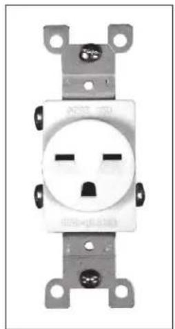
This is the same type of receptacle used for many 240-volt window air conditioners

POWER FACTOR CORRECTION IN SUB 2
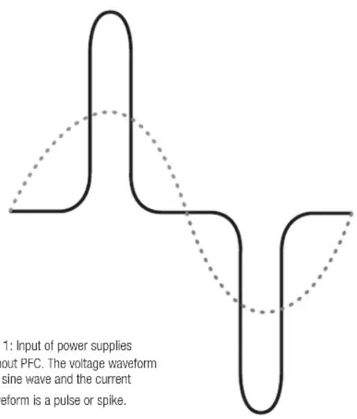
Fig. 1: Input of power supplies without PFC. The voltage waveform is a sine wave and the current waveform is a pulse or spike.
Q. What is the layman's explanation of Power Factor Correction (PFC)?
A. The Power Factor is a measure of the real power available. It is the ratio of real power to apparent power. It is a number which can vary from 0 to 1.0. The lower the number, the lower the real power. Poor power factor has two causes: phase difference between AC voltage and current as found in heavy industries mainly due to inductive loads (ex. motors) and current waveform distortion as found in electronics equipment.
In power supplies without PFC, current can only flow at the peak of AC voltage crests and these peaks can be huge. In power supplies employing PFC current flows continuously and in the same shape as the voltage. To elaborate, power supplies without PFC draw the AC input current in short bursts or spikes relative to the line voltage, as shown in Fig. 1.
POWER FACTOR CORRECTION IN SUB 2 (continued)

This Power Factor can be improved by using PFC circuits. These circuits 'smooth out' the pulsating AC current, improving the PF and reducing the chances of a circuit breaker tripping prematurely.
There are two basic types of PFC: Passive and Active. Passive PFC circuits are less expensive and typically can correct the PF to about 0.85. Active PFC circuits are built into the switchmode power supply and can increase the PF to 0.98 or higher. The closer the PF comes to 1.0, the better the performance of the power supply. The SUB 2's amplifier employs an active PFC circuit with a resulting PF of 0.99! Ideally, we want to end up with the input voltage and current waveforms being sinusoidal and in-phase with each other, as shown in Fig. 2.
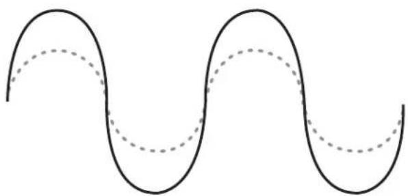
Fig.2:Voltage and Current waveforms are sinusoidal and in-phase. (PF = 1)

LIMITED WARRANTY
Paradigm® Reference Signature SUB 1 and SUB 2 are warranted to be and remain free of manufacturing and/or material defects for a period of three (3) years from the date of the original retail purchase. Within this specified period, repair, replacement or adjustment of parts for manufacturing and/or material defects will be free of charge.
Thermal or mechanical abuse/misuse is not covered under warranty.
Limitations:
Warranty begins on date of original retail purchase from an Authorized Paradigm® Reference Dealer only. It is not transferable;
- Warranty applies to product in normal home use only. If the product is subjected to any of the conditions outlined in the next section, warranty is void;
- Warranty does not apply if the product is used in professional or commercial applications.
Warranty is Void if:
The product has been abused (intentionally or accidentally);
- The product has been used in conjunction with unsuitable or faulty equipment;
- The product has been subjected to damaging signals, derangement in transport, mechanical damage or any abnormal conditions;
The product (including cabinet) has been tampered with or damaged by an unauthorized service facility;
The serial number has been removed or defaced.
Owner Responsibilities:
- Provide normal/reasonable operating care and maintenance;
- Provide or pay for transportation charges for product to service facility;
- Provide proof of purchase (your sales receipt given at time of purchase from your Authorized Paradigm® Dealer).
Should servicing be required, contact your nearest Authorized Paradigm® Reference Dealer, Paradigm Electronics Inc., or Import Distributor (outside the U.S. and Canada) to arrange, bring in or ship prepaid any defective unit. Visit our website at www.paradigm.com for more information.
Paradigm Electronics Inc. reserves the right to improve the design of any product without assuming any obligation to modify any product previously manufactured.
This warranty is in lieu of all other warranties expressed or implied, of merchantability, fitness for any particular purpose and may not be extended or enlarged by anyone. In no event shall Paradigm Electronics Inc., their agents, or representatives be responsible for any incidental or consequential damages. Some jurisdictions do not allow limitation of incidental or consequential damages, so this exclusion may not apply to you.
Retain this manual and your sales receipt for proof of warranty term and proof of purchase.
TECHNICAL SPECIFICATIONS

SUB1
Design:
Hexagonal cabinet with multiple high-excursion drivers radially aligned in a vibration-canceling design architecture, patented built-in Ultra-Class-D power amplifier, sealed enclosure, PBK interface, removable grilles
Amplifier:
High-Current Discrete-Output, Dual amplifier design, 3,400 watts Dynamic Peak / 1,700 watts RMS Sustained (850 watts each)
Amplifier Features:
Auto-on / off, Trigger-on / off, soft clipping, electrical shorting protection, thermal protection
Bass Drivers:
Six 203-mm (8 in) mineral-filled polypropylene cones, overmolded FEA-optimized NLC™ surrounds, 38-mm (1-1/2 in) 4-layer long-excursion voice coils, high-temperature composite Nomex® reinforced formers, advanced spiders, 4-3/4 lb (2.1 kg) hard ferrile magnet structure, AVS™ die-cast heatsink chassis
Low-Frequency Extension*: 12 Hz (DIN)
Subwoofer Cut-Off Frequency:
Variable 35 Hz -150 Hz, Bypass Option
Sub / Sat Phase Alignment:
Variable 0^ - 180^
Line-Level Input:
RCA (S/E) Left and Right or Sub-Out / LFE or Balanced XLR. From Sub-Out / LFE-Out of preamp/processor or other line-level source
Line-Level Input Sensitivity:
100 mV mono
Line-Level Input Impedance:
RCA: 10k ohms, XLR: 20k ohms
Accessory Included:
Paradigm Perfect Bass Kit
Height, Width, Depth
20-1/4 in x 19-7/8 in x 17-7/8 in
Diameter of Hexagon
50.5 cm / 19-7/8 in
Weight:
49.4 kg / 109 lb
Available Finishes:
Cherry, Piano Black

SUB2
Design:
Hexagonal cabinet with multiple high-excursion drivers radially aligned in a vibration-canceling design architecture, patented built-in Ultra-Class-D power amplifier, sealed enclosure, PBK interface, non-removable grilles for safety
Amplifier:
High-Current Discrete-Output, 9,000 watts Dynamic Peak / 4,500 watts RMS Sustained*
Universal Input Power:
Allows the SUB 2 to operate connected to any line voltage between 108 volts and 265 volts. However, in order to achieve maximum continuous performance, we highly recommend connecting to a 240-volt line. More information on this unique feature available on the preceding pages
Power Factor Correction:
Prevents overheating / tripping of the circuit breakers. More information on this unique feature available on the preceding pages
Amplifier Features:
Auto-on / off, Trigger-on / off, soft clipping, electrical shorting protection, thermal protection
Bass Drivers:
Six 254-mm (10 in) mineral-filled RCR ^TM polypropylene cones, FEA-optimized thermoset foam surrounds,76-mm (3 in) 10-layer long-excision voice coils, high-temperature composite Nomex reinforced formers, dual advanced spiders, 12-2/3 lb (5.7 kg) hard ferrite magnet structure, massive center heatsink and oversize pole piece, AVS die-cast heatsink chassis
Low-Frequency Extension
7 Hz (DIN)
Subwoofer Cut-Off Frequency:
Variable 35Hz - 150Hz Bypass Option
Sub / Sat Phase Alignment:
Variable 0^ - 180^
Line-Level Input:
RCA (S/E) Left and Right or Sub-Out / LFE or Balanced XLR. From Sub-Out / LFE-Out of preamp/processor or other line-level source
Line-Level Input Sensitivity:
100 mV mono
Line-Level Input Impedance:
RCA: 10k ohms, XLR: 20k ohms
AC Voltage: (See section on 'Universal Input Power SUB 2' earlier in manual)
120v (at 3,000 watts) - 50 / 60 Hz
240v (at 4,500 watts) - 50 / 60 Hz
Accessory Included:
Paradigm Perfect Bass Kit
Height, Width, Depth
24-1/2 in x 23-3/4 in x 22-3/8 in
Diameter of Hexagon
60.4 cm / 23-3/4 in
Weight:
106 kg / 230 lb
Available Finishes:
Cherry, Piano Black
NOTES


NOTES


Paradigm, Paradigm Reference, Signature and all associated proprietary and patented designs and technologies are registered trademarks of Paradigm Electronics Inc. Copyright © Paradigm Electronics Inc. All rights reserved. All other trademarks are the property of their respective owner(s). Paradigm Electronics Inc. reserves the right to change specifications and/or features without notice as design improvements are incorporated.
Photography: Jason Hartog Photography. Lifestyle Images: istockphoto.com. Printed in Canada.

Paradigm Electronics Inc.
In the U.S.: MPO Box 2410, Niagara Falls, NY 14302
In Canada: 205 Annagem Blvd., Mississauga, ON L5T 2V1

MODE D'EMPLOI
SUB 1 et SUB 2

SONORITE A HAUTE D'EFINITION
PBK

DIRECTIVES EUROPEENNES SUR LE RECYCLAGE ET LE TRAITEMENT DES DECHETS
Specifications techniques

39
Remarques

SUB 1 ET SUB 2 PARADIGM ^MD REFERENCE SIGNATURE
RCA:10k ohms, XLR:20k ohms
Paradigm Perfect Bass Kit*
RCA:10k ohms,XLR:20k ohms
Paradigm Perfect Bass Kit
62.2 cm x 60.4 cm x 57.8 cm
24-1/2 in x 23-3/4 in x 22-3/8 in
Hexagon :
60.4 cm / 23-3/4 in
Poids :
106 kg / 230 lb
Paradigm Electronics Inc.
Aux E.-U.: MPO Box 2410, Niagara Falls, NY 14302
Au Canada:205,boul. Annagem, Mississauga Ontario) L5T 2V1


- PARADIGM® REFERENCE SIGNATURE SUB 1 AND SUB 2
- The Paradigm Perfect Bass KitTM
- THE DESIGN & TECHNOLOGY BEHIND
- YOUR NEW SUBWOOFER
- Vibration-Canceling Design Architecture
- YOUR NEW SUBWOOFER (continued)
- SIGNATURE SUB 1
- SIGNATURE SUB 2
- BIG POWER. Compact Package. Two Cutting-Edge Ultra-Class-D™ Amplifiers:
- Cutting-Edge 'Kilomax' Amplifier Platform with Universal Input Power and Power Factor Correction
- SAFETYPRECAUTIONS
- READ THIS SECTION CAREFULLY BEFORE PROCEEDING!
- WARNING
- IMPORTANT SAFETY INSTRUCTIONS
- PLACEMENT & CONNECTION SUB 1 & SUB 2
- PLACEMENT & CONNECTION SUB 1 & SUB 2 (continued)
- YOURNEW SUBWOOFER
- Break-In
- Cleaning
- ABSOLUTE POWER ... IS VERY VERY COOL
- A Note About the Absolutely Insane Power Capabilities of SUB 2
- ROOM PLACEMENT &
- THE PARADIGM PERFECT BASS KIT™
- PBK
- THE ADVANTAGES OF USING TWO SUBWOOFERS IN YOUR LISTENING ROOM
- PARADIGM PERFECT BASS KITTM:
- A TRUE AUDIOPHILE SOLUTION TO THE PROBLEMS OF THE ROOM
- THE PARADIGM PERFECT BASS KIT
- Your PBK Kit includes:
- Steps to assemble stand and microphone:
- How does PBK do what it does?
- Getting Started
- Before starting the procedure, note the following:
- THE PROCEDURE
- Install the Software
- Confirm Your Software Version Once the Software is Installed
- THE PARADIGM PERFECT BASS KIT™ (continued)
- Check Online for the Latest Version of PBK Software
- To update the version do the following:
- Positioning the Microphone
- CONNECTION & CONTROL
- INPUT FACILITIES
- Low-Level Input 2 RCA Connection Options (Figs. 3a, 3b)
- Low-Level Input—Balanced XLR (Fig. 4)
- CONTROL FACILITIES
- Auto-On/Standby
- Trigger-On/Off
- Subwoofer Level
- Subwoofer Cut-Off and Bypass Option
- Phase Alignment
- THE USB PORT / PBK INTERFACE
- FINE TUNING
- SETTING SUBWOOFER CONTROLS
- CONNECTING SUB 2 TO A 240-VOLT LINE
- CONNECTING SUB 2 TO A 240-VOLT LINE (continued)
- POWER FACTOR CORRECTION IN SUB 2
- POWER FACTOR CORRECTION IN SUB 2 (continued)
- LIMITED WARRANTY
- Thermal or mechanical abuse/misuse is not covered under warranty.
- Limitations:
- Warranty is Void if:
- Owner Responsibilities:
- TECHNICAL SPECIFICATIONS
- SUB1
- Design:
- Amplifier:
- Amplifier Features:
- Bass Drivers:
- Line-Level Input:
- Line-Level Input Sensitivity:
- Line-Level Input Impedance:
- Accessory Included:
- Height, Width, Depth
- Diameter of Hexagon
- Weight:
- Available Finishes:
- SUB2
- Universal Input Power:
- Power Factor Correction:
- Low-Frequency Extension
- Subwoofer Cut-Off Frequency:
- Sub / Sat Phase Alignment:
- NOTES
- Paradigm Electronics Inc.
- DIRECTIVES EUROPEENNES SUR LE RECYCLAGE ET LE TRAITEMENT DES DECHETS
- SUB 1 ET SUB 2 PARADIGM MD REFERENCE SIGNATURE
- Hexagon :
- Poids :
Brand : Paradigm
Model : SUB 2
Category : Subwoofer