
CMI36 - DJ Equipment Marquant - Free user manual and instructions
Find the device manual for free CMI36 Marquant in PDF.
| Product Type | DJ mixer with CD player and iPod |
| Brand | Marquant |
| Model | CMI36 |
| Power Supply | AC 100-240V, 50/60Hz (voltage selector) |
| Power Consumption | Approximately 30 W |
| Dimensions (W x D x H) | 482 x 315 x 105 mm |
| Weight | 4.5 kg |
| Main Features | Dual CD player, iPod input, pitch control, jog/shuttle, loop, track programming, crossfader, 3-band equalizer, microphone input |
| Pitch Range | ±16%, ±32%, ±100% |
| Audio Outputs | Stereo master output RCA, headphone output (6.35 mm jack), video output |
| Audio Inputs | 2 x line/phono input (RCA), microphone input (6.35 mm jack), iPod input (dedicated connector), USB |
| Compatibility | CD, CD-R/RW, iPod/iPhone |
| Special Functions | Loop, reloop, cue, quick search, 20-track program, continuous or single play |
| Display | LCD screen with time, loop, track indicators, etc. |
| Maintenance and Cleaning | Clean with a soft dry cloth. Do not use solvents. Avoid dust. |
| Safety | Unplug before cleaning. Do not expose to moisture. Use only supplied accessories. |
| Spare Parts and Repairability | Contact Marquant customer service or an authorized technician for repairs. |
Frequently Asked Questions - CMI36 Marquant
User questions about CMI36 Marquant
0 question about this device. Answer the ones you know or ask your own.
Ask a new question about this device
Download the instructions for your DJ Equipment in PDF format for free! Find your manual CMI36 - Marquant and take your electronic device back in hand. On this page are published all the documents necessary for the use of your device. CMI36 by Marquant.
USER MANUAL CMI36 Marquant
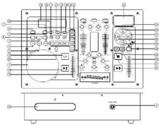
1. HEADPHONE JACKS
Use to connect for audio monitoring with headphones.
2. JOG & SHUTTLE WHEELS
Shuttle : Use the dial to select the scanning direction and speed. The disc is scanned in the forward direction when the shuttle dial is turned clockwise from the neutral position, in the reverse direction when the shuttle dial is turned counterclockwise. The scanning speeds up when the shuttle dial is turned faster.
Jog : In pause mode, if you turn the jog, the point at which the sound is being produced moves by a number of frames corresponding to the number of clicks. Clockwise moves the point forward; counterclockwise moves the point backward. In play mode, the jog increases or decreases the speed of the song. (clockwise : increase , counterclockwise : decrease ).
3. TIME BUTTON
Use this knob to choose the time mode : Elapsed time, remaining time or total remaining time.
4. REPEAT BUTTON
Use this button to repeat one track or all the track of the CD.
5. IN BUTTON (LOOP SYSTEM)
This button sets the beginning of the loop. The Loop indicator on the display flashes.
6. CONT. / SINGLE BUTTON
Press these to switch between the SINGLE and CONTINUOUS play mode. The selected mode is indicated on the LCD. In SINGLE mode, after each track, the unit stops the reading. In CONTINUOUS mode, the unit reads all track and stops.
7. PROG BUTTON
In STOP mode, you can program several tracks (20 tracks max.) :
- Press the STOP button to enter in the stop mode
- Press the PROG button to enter in the program mode
- Use the skip track buttons to choose the track you want to listen then press the PROG button to enter your choice.
-Use one more time the skip track buttons to choose the track you want to listen then press the PROG button to enter your choice.
-Repeat the operation to select all the track you want to listen
-Press the play / pause button to start the playback
8. OUT BUTTON (LOOP SYSTEM)
When you press this button, you set the end point of the seamless loop and you start the loop. To finish the loop, press again this button.
9. TARCK SELECT BUTTONS
Pressing 0-9 buttons, allow you to select tracks from the CD.
10. RELOOP BUTTON ( LOOP SYSTEM )
This button is used to start the last saved loop. To finish the loop, press the reloop button.
11. SKIP I<< BUTTON
Use this switch to re-start the track or to select the last track.
12. CUE BUTTON
Pressing the CUE button during play provides a return to the position at which play was started.
13. +10 BUTTON
Use this button to jump of 10 tracks in one press.
14. PLAY / PAUSE BUTTON
Each time you press the PLAY/PAUSE button, the operation changes from play to pause or from pause to play.
15. SKIP >>I BUTTON
Use this knob to select the next track.
16. PITCH CONTROL
Use this fader to increase or decrease the speed of the track.
17. PITCH BEND + BUTTON
The pitch will automatically rise when the + button is pressed and return to the original pitch when it is released.
18. PITCH BUTTON
If you push this button, the adjustment of the pitch potentiometer is available.
19. DISPLAY
20. PITCH BEND - BUTTON
The pitch will drop while the -button is pressed and return to the original pitch when it is released.
21. EJECT BUTTON
Press to load or eject disk. Each press will open or close the disk tray.
NOTE: disc holder will not open unless stop or pause button has been pushed fir.
22. DISC-TRAY
To enter the disc, please refer to the explanations under 6.2 CD-tray.
23. SEARCH BUTTON
Pressed the button to switch the function of jog dial between SEARCH and PITCH BEND, when the indicator LED is light, dial the jog for quick search forward and backward, when the indicator LED is off, dial the jog for pitch bend function, If the jog is unmoved for 8 seconds, the indicator is off, and the jog is for pitch bend function.
24. IPOD JACK
Use to connect with the IPOD.
25. MENU BUTTON
Press to enter or exit the menu.
26. SCROLL ◀ BUTTON
Press this button to select last item of menu.
27. SCROLL ▶ BUTTON
Press this button to select next item of menu.
28. REPEAT BUTTON
Press this button to repeat one track or all tracks of the IPOD. One press is single, and double is all. If you press it three times, the track returns to normal.
29. PITCH SYSTEM
Use the fader to increase or decrease the speed of the track. The range of adjustment includes +/-16%, +/-32%, +/-100%.
- SKIP |← BUTTON
Use this button to select the last track. Press it about for 2 seconds to play fast backward.
- SKIP ➤️ BUTTON
Use this button to select the next track. Press it about for 2 seconds to play fast fastward.
- STOP BUTTON
Press this button to stop the playback.
- ENTER BUTTON
Press this button to enter what you select.
MIXER FUNCTION
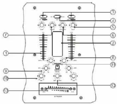
1. INPUT FADER
Controls individual source levels for CH1-2 in the mix
2. LED METER
Indicates the master output level
3. INPUT TOGGLE SWITCH
Selects which source will be live to that channel bass on what you have connected to the rear panel input section. In CD1-2 position the internal CD units are active
4. CUE FOR CH1-2
Selects which source will be live to that channel for CH1 &CH2
5. CH1&CH2 GAIN CONTROL
Adjusts CH1&CH2 level
6. CUE LEVEL CONTROL
Adjusts cue volume
7. DJ MIC
Adjust microphone level
8. HIGH FADER 1-2
Adjust CH1&CH2 equalization of high
9. MID FADER 1-2
Adjust CH1&CH2 equalization of mid
10. LOW FADER 1-2
Adjust CH1&CH2 equalization of low
11. FADER START
Activation allows you to start the CD players from you crossfader. Travel from left to right will start the right CD player and pause the left CD player.
12. MASTER LEVEL
Adjust master level output.
13. REPLACEABLE CROSSFADER
Achieves clean segues between the two input channels. Hard left selects channel 1. Hard right selects channel 2. With the crossfader centered, both assigned channels are live. Use the crossfader for fast and seamless segues from one selected channel to the other.
RER PANEL FUNCTION
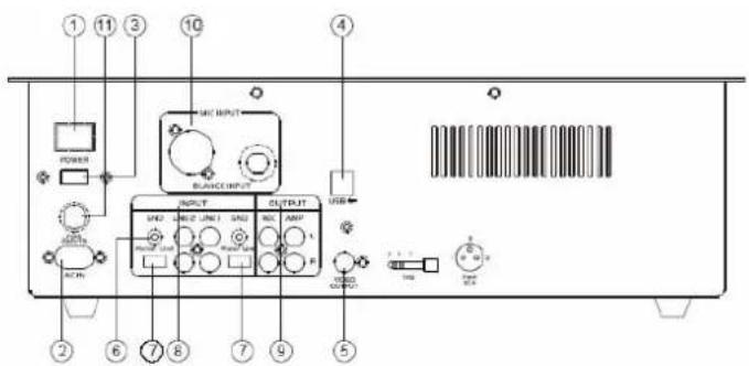
1. POWER BUTTON
Press the power switch to turn the unit on. To switch the power off press the power switch again.
2. AC CORD
Use this cable to connect the AC mains power to the unit.
3. POWER SUPPLY
Use this selector to choose the good Power supply. (Several countries have another power supply)
4. USB
Connect to the USB.
5. VIDEO OUTPUT
The video for each CD player is an output for these jacks. Connect to the line input of the mixer
6. GND
Grounding lug for turntable connection. Always use this connection when using turntables.(Your turntable cable should have a grounding wire)
7. LINE/PHONO INPUT SWITCH
Use this to allow either line level or phono level equipment to be plugged into your channel inputs. When phono input is selected, your signal is fed directly to the high-quality RIAA phono preamplifiers. Line level sources will verload the sensitive phono pre-amps and will sound very bad, so always be sure to toggle the line/phono switch over to line before connection of line sources.
8. INPUT
Plug in the line level device such as tape deck or additional CD player here.
9. STEREO MAIN OUTPUT
Unbalanced RCA connectors controlled by the master fader.
10. MIC INPUT
11. FUSE
FRENCH
FONCTIONS DU PANNEAU AVANT
1. PRISES CASQUE
1. FADER INPUT
1. HEADPHONE CONTACT
1. INGANGS FADER
CMi-36 equipment is covered by a 1-year warranty on parts and labour except for Crossfaders (90 days).
The following rules apply from the day the equipment leaves the factory:
The date on the invoice is considered to be the date the warranty begins.
Only companies approved by CMi-36 are allowed to work on the equipment. Warranty becomes void when other service technicians open the equipment.
During warranty period, defective equipment must be sent by pre-paid mail in the original box.
CMi-36 will return the goods by pre-paid mail during the first year of warranty; thereafter the mailing cost is to be paid by the recipient
Potentiometers have a limited lifetime and are not covered by the manufacturer for more than normal use.
For all service enquiries, refer to your local distributor, as he is best able to help you.
SPECIFICATIONS :
Anti-Shock Buffer Memory : 40 seconds
Power supply : 115 / 230V 50/60Hz


- HEADPHONE JACKS
- JOG & SHUTTLE WHEELS
- TIME BUTTON
- REPEAT BUTTON
- IN BUTTON (LOOP SYSTEM)
- CONT. / SINGLE BUTTON
- PROG BUTTON
- OUT BUTTON (LOOP SYSTEM)
- TARCK SELECT BUTTONS
- RELOOP BUTTON ( LOOP SYSTEM )
- SKIP I<< BUTTON
- CUE BUTTON
- +10 BUTTON
- PLAY / PAUSE BUTTON
- SKIP >>I BUTTON
- PITCH CONTROL
- PITCH BEND + BUTTON
- PITCH BUTTON
- DISPLAY
- PITCH BEND - BUTTON
- EJECT BUTTON
- DISC-TRAY
- SEARCH BUTTON
- IPOD JACK
- MENU BUTTON
- SCROLL ◀ BUTTON
- SCROLL ▶ BUTTON
- REPEAT BUTTON
- PITCH SYSTEM
- MIXER FUNCTION
- INPUT FADER
- LED METER
- INPUT TOGGLE SWITCH
- CUE FOR CH1-2
- CH1&CH2 GAIN CONTROL
- CUE LEVEL CONTROL
- DJ MIC
- HIGH FADER 1-2
- MID FADER 1-2
- LOW FADER 1-2
- FADER START
- MASTER LEVEL
- REPLACEABLE CROSSFADER
- RER PANEL FUNCTION
- POWER BUTTON
- AC CORD
- POWER SUPPLY
- USB
- VIDEO OUTPUT
- GND
- LINE/PHONO INPUT SWITCH
- INPUT
- STEREO MAIN OUTPUT
- MIC INPUT
- FUSE
- FRENCH
- FONCTIONS DU PANNEAU AVANT
- PRISES CASQUE
- FADER INPUT
- HEADPHONE CONTACT
- INGANGS FADER
- SPECIFICATIONS :
Brand : Marquant
Model : CMI36
Category : DJ Equipment