USER MANUAL IBS 7944 N I79S44N0 NEFF
Operating and installation instructions
EFF
en page 18–32
fr pages 33–47
nl pagina 48–62
it pagina 63 - 77
es página 78 - 92
el Σελίδα 93 - 107
Fig. 1
GAS
GAZ
ELECTRO
ÉLECTRO
FIRE HAZARD
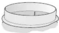
4x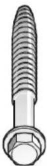
Table of contents
Information on protection of the environment 19
Before using the appliance for the first time 19
Safety Instructions 20
Intended use 20
Technical safety 20
Special information for gas cookers 21
Proper use 22
Correct installation 22
Operating modes 23
Exhaust-air mode 23
Circulating-air mode 23
Operation 24
Cleaning and Care 25
Removing and installing the grease filters 26
Removing and installing the metal-mesh grease filters 26
Installing and removing the activated carbon filters 26
Changing the bulbs 27
Installation instructions 28
Connecting Pipes 28
Electrical Connections 29
Installation 30
Installation preparations 30
Attachment 31
Installing the flue ducts 32
Disposal of transport packaging
Your new appliance was sent to you in protective packaging. All utilised materials are environmentally safe and recyclable. Please help us by disposing of the packaging in an environmentally friendly manner.
Packaging parts can be hazardous for children. Therefore keep them outside the reach of children.
Disposal of the old appliance
Old appliances are not worthless rubbish. Valuable raw materials can be reclaimed by recycling old appliances.
This appliance is identified according to the European Directive 2002/96/EC on waste electrical and electronic equipment – WEEE). The directive specifies the framework for an EU-wide valid return and re-use of old appliances.

Before disposing of your old appliance, render it unusable.
Never treat your old appliance as non-recyclable waste!
Please ask your dealer or inquire at your local authority about current means of disposal.
Ensure that the old appliance is kept childproof until it is disposed of.
BEFORE USING THE APPLIANCE FOR THE FIRST TIME
NOTE: These operating instructions apply to several appliance models. It is possible that individual features are described which do not apply to your appliance.
Before switching on your new appliance, please read the operating instructions carefully. They contain important information on safety and how to use and look after the appliance.
Keep the operating instructions in a safe place and pass them on to any subsequent owner of the appliance.
Faults
Please contact customer service regarding any queries or faults.
(See list of customer service centres).
When calling, please quote:
E-no. FD
The numbers can be found on the rating plate, after removal of the grease filter, inside the extractor hood.
Enter the numbers in the above fields.
Intended use
This extractor hood complies with the stipulated safety regulations. Improper use may result in injury or damage. The extractor hood may be used in the household only. The manufacturer is not liable for damage which is caused by improper use or incorrect operation. The manufacturer cannot be made responsible for damage which can be attributed to non-observance of the safety instructions.
RISK OF INJURY
Do not allow children to play with the extractor hood! Adults and children must never operate the appliance unsupervised
- if they are not physically or mentally capable of doing so, or if they do not have the knowledge and experience to operate the appliance correctly and safely.
Technical safety
The extractor hood left the factory in perfect condition. Nevertheless check the appliance for visible damage before installation. If it is damaged, do not switch it on! If the power cord of the extractor hood is damaged, it must be replaced by the manufacturer, his customer service or a similarly qualified person to prevent hazardous situations. Only a qualified technician may install (including electrical connection), service or repair the extractor hood. Always isolate the extractor hood by pulling out the mains plug or switching off the fuse!
If the appliance is improperly installed, serviced or repaired, the user may be placed in considerable danger for which the manufacturer is not liable. Changes to the electrical or mechanical installation are dangerous and must not be undertaken! They may also cause the extractor hood to malfunction.
Heating appliances which are dependent on ambient air, e.g. gas, oil, wood, or solid-fuel heaters, instantaneous water heaters, hot water boilers, hobs or ovens, and which draw combustion air out of the installation room and whose exhaust gases are conveyed to the exterior by a flue.
RISK OF POISONING
If the extractor hood is operated at the same time as a heating appliance which is dependent on ambient air, there is a risk of poisoning due to combustion gases being drawn back in.
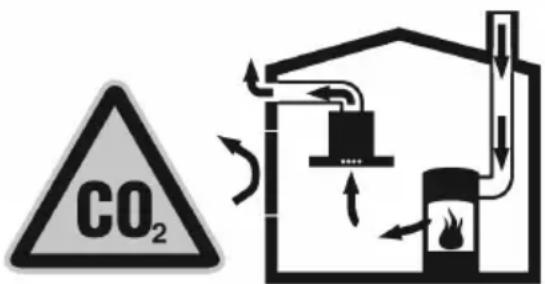
Safe operation is possible provided the low pressure in the installation room of the heating appliance does not exceed 4Pa (0.04mbar). This can be achieved if the combustion air can flow through non-closable openings, e.g. in doors, windows, in conjunction with air intake/exhaust air wall boxes or by other technical measures.
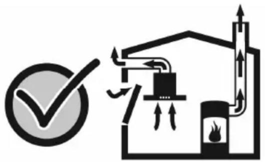
Adequate intake air must therefore always be provided. An intake/exhaust air wall box alone does not ensure compliance with the limit value.
NOTE: When making your evaluation, always consider the entire ventilation system in the home. Include the advice of a competent heating engineer when making your evaluation.
If the extractor hood is used in circulating air mode only, it can be operated without any restrictions.
When installing the extractor hood above gas hobs, observe the appropriate national statutory regulations (e.g. in Germany: Technische Regeln Gasinstallation TRGI). Observe the currently valid installation regulations and instructions of the gas appliance manufacturer. During installation, ensure that only one side of the extractor hood is situated directly next to a high-sided unit or a wall. Otherwise, there is a risk of heat build-up. The gap between the extractor hood and the wall or high-sided unit must be at least 50 mm.
RISK OF BURNS
Do not operate more than 2 gas cooking areas simultaneously over a period of max. 15 minutes at maximum thermal load. Due to the effect of the heat there is a risk of burns if the surfaces of the housing are touched!
Note that one large burner of more than 5 kW (Wok) is equivalent to the power of 2 gas burners. The extractor hood may be damaged by the intense heat. Never operate a gas cooking area without a cooking utensil on it. Regulate the flame in such a way that it does not project over the cooking utensil.
Proper use
Clean the extractor hood thoroughly before using for the first time.
Before cleaning and servicing the extractor hood, isolate it from the power supply by pulling out the mains plug or switching off the fuse.
Bulbs (especially halogen bulbs) become very hot during operation. Even some time after the appliance has been switched off, there is still a risk of burns!
Before changing bulbs, isolate the extractor hood from the power supply and leave the bulbs to cool down!
Do not operate the extractor hood without bulbs inserted.
Always switch on the extractor hood if a hotplate is being used. If the extractor hood is not switched on, condensation may form. As a result, the appliance may corrode.
Do not place any objects on the extractor hood.
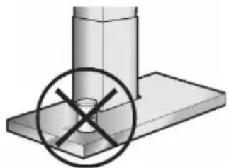
RISK OF FIRE
Do not flambé under the extractor hood or work with a naked flame. When switched on, the extractor hood draws flames into the filter. There is a risk of fire due to deposits on the grease filter!
Do not leave pans, frying pans or deep-fat fryers unattended if you are cooking food with oils or fats, e.g. chips. Overheated oils or fats can easily ignite!
A risk of fire can be prevented by cleaning the grease filters regularly and changing the activated-carbon filter in good time.
Never operate the extractor hood without grease filters.
Correct installation
Check the manufacturer's specifications for the cooker to determine whether an extractor hood can be operated over it. If the manufacturer of the cooker has not specified any significant safety distances, the following minimum distances apply:
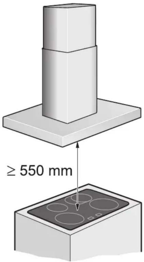
- 550 mm between electric hob and the lower edge of the extractor hood, Fig. 1.
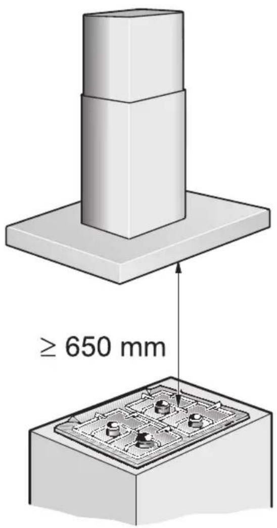
- 650 mm between gas hob (upper edge of pan support) and the lower edge of the extractor hood, Fig. 1. If various cookers are used, the greatest indicated distance applies. The width of the extractor hood must correspond to the width of the cooking area. The extractor hood must not be installed over a solid fuel heating appliance which may be a fire risk (e.g. flying sparks) unless the heating appliance has a closed, non-detachable cover and the country-specific regulations are observed. This restriction does not apply to gas cookers and gas hobs. To avoid damaging the hob, cover it when installing the extractor hood.
The extractor hood can be used in exhaust air and circulating air mode.
Exhaust-air mode
The air which is drawn in is cleaned by the grease filters and conveyed to the exterior by a pipe system.
Appliance dimensions: Exhaust air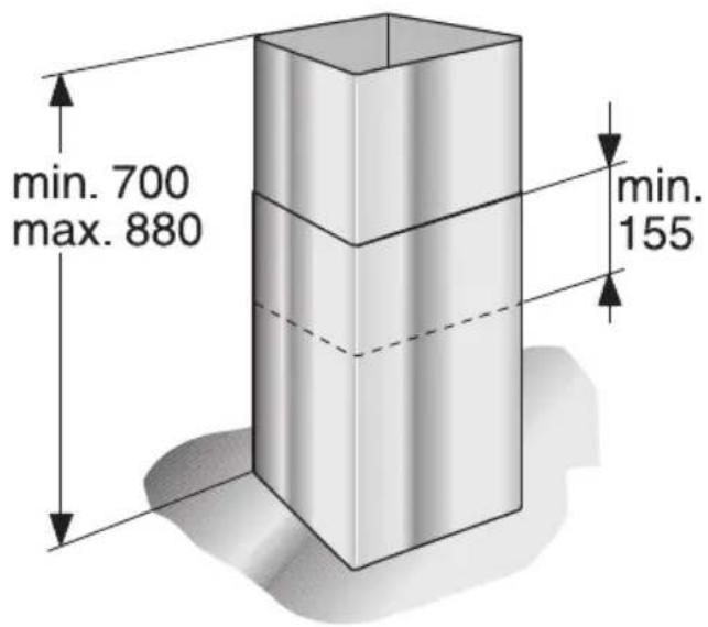
Circulating-air mode
The air that is drawn in is cleaned by the grease filters and an activated carbon filter and then conveyed back into the kitchen.
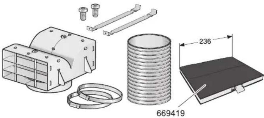
An activated carbon filter must be installed to bind odors in circulating-air mode (see "Removing and installing the grease filters").
The complete installation set as well as the replacement filters are available from specialist outlets, customer service, or the Online Shop. The accessory number can be found at the end of the operating instructions.
Appliance dimensions: Circulating air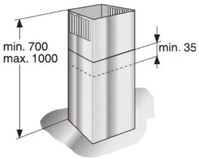
The description of the operation applies to several appliance models. It is possible that individual features are described which do not apply to your appliance.
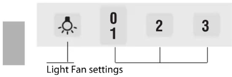
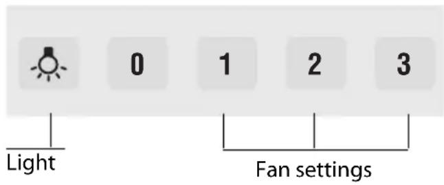
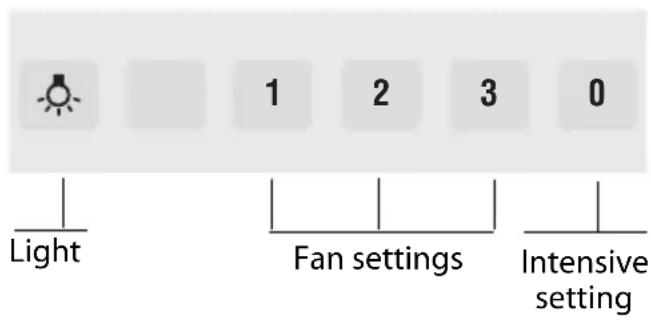
NOTE: It is recommended to switch on the blower when you start cooking and not to switch it off again until several minutes after you have finished cooking. In this way, kitchen fumes are removed most effectively.
Switching on the fan and selecting the fan settings
Press button 1. If kitchen fumes are thicker, switch to setting 2 or 3.
The light can be switched on and off independently of the fan.
For appliances with Intensive setting
The Intensive setting P generates maximum performance. It can be used if thick fumes or strong odors occur temporarily.
LOOKING AFTER THE APPLIANCE
Suitable cleaning agents and care products for your appliance can be purchased via the Hotline or from the Online Shop (see cover page).
Appliance surfaces
NOTE: Observe the warranty regulations in the enclosed service booklet.
The appliance surfaces and controls are scratch-sensitive. Therefore observe the following cleaning instructions:
- Avoid cleaning the extractor hood with dry cloths, abrasive sponges, scouring agents, cleaning agents containing sand, soda, acid, chlorine or any other aggressive substances.
- Clean the appliance surfaces and controls with a soft, damp cloth, washing-up liquid or a mild window cleaner only.
- Do not scrape off dried dirt, but moisten with a damp cloth. – Clean carefully in the area of the controls to avoid liquid from getting into the electronics.
NOTE: Clean the stainless steel surfaces in the direction of the ground surface only!
Do not use stainless steel cleaner for the control buttons!
The metal-mesh grease filters absorb the grease particles from the kitchen fumes. ▷ The filter mats consist of fire-proof metal.
RISK OF FIRE
As the filters become more saturated with greasy residue, the flammability increases. The function of the extractor hood may also be impaired.
The risk of fire is prevented by cleaning the metal-mesh grease filters in good time. ▷ When cleaning the grease filters, also remove grease deposits from the accessible parts of the housing with a damp cloth.
▶ Under normal operation (daily 1 to 2 hours), the metal-mesh grease filters must be cleaned 1x month.
... in the dishwasher
The metal-mesh grease filters can be cleaned in the dishwasher. Slight discolouration may occur but this will not affect the function of the grease filters. The filters must be placed loosely in the dishwasher. They must not be wedged in.
NOTE: Do not clean heavily saturated metal-mesh grease filters together with utensils.
... by hand
When cleaning by hand, soak the grease filters in a hot detergent solution, brush off the dirt, rinse thoroughly and leave to dry. Do not use any aggressive, acidic or alkaline cleaning agents. If dirt is particularly stubborn, we recommend using a special grease solvent spray. This can be ordered via the Online Shop.
Before removing and installing the grease filters, always follow the instructions and warnings in the chapter entitled "Safety instructions"!
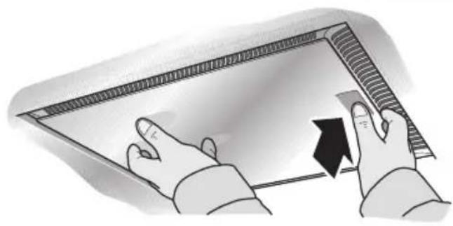
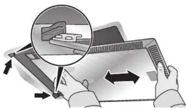
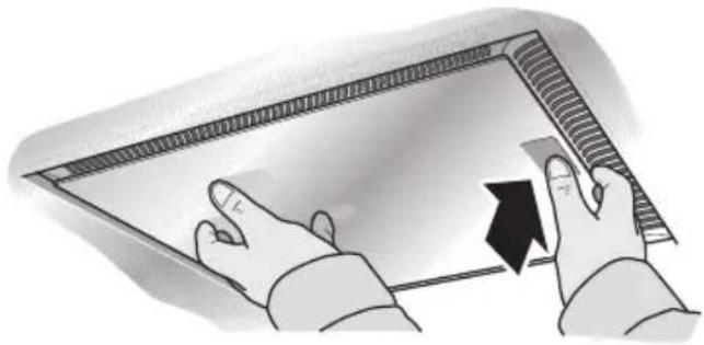
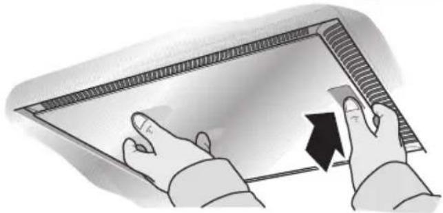
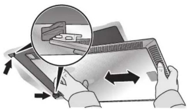
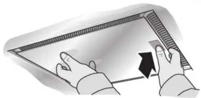
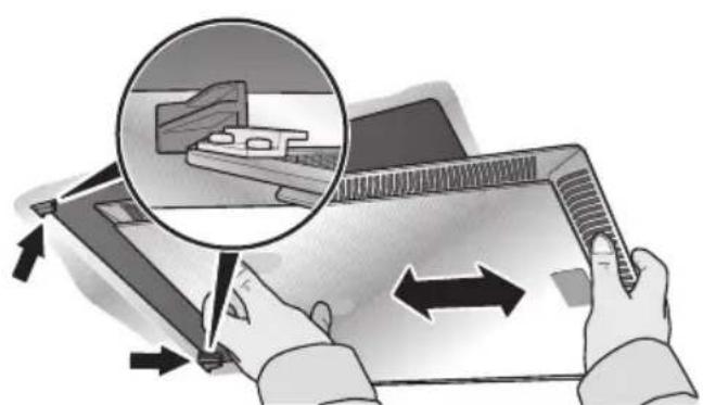
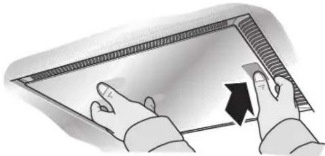
- Open the lock and fold down the grease filters. In doing so, hold the underside of the grease filters with your other hand.
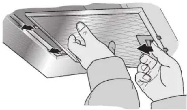
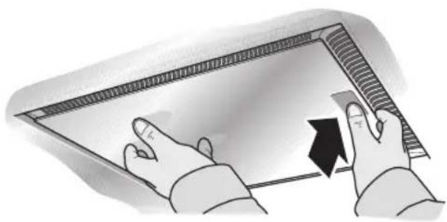
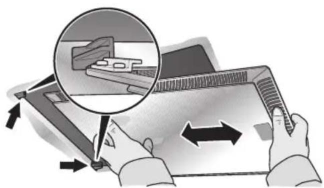
(for appliances with edge extraction)
- Clean the grease filters.
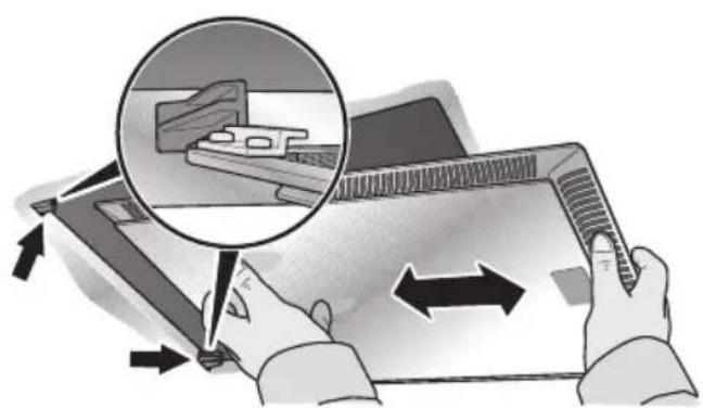
- Reinsert the cleaned grease filters.
Activated carbon filters bind the odours in circulating-air mode.
Installing and removing the activated carbon filters
- Remove the grease filters (see Removing and installing the metal-mesh grease filters).
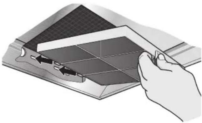
- Insert the activated carbon filter.
- Lock the catch.
- Reinsert the grease filters (see Removing and installing the metal-mesh grease filters).
Changing the activated carbon filter
Under normal operation (daily 1 to 2 hours) the activated carbon filters must be replaced approximately 2x year. The activated carbon filter is available from specialist outlets, customer service or the Online Shop (see Optional accessories). Use original filters only. Activated carbon filters do not contain any pollutants. They can be disposed of in the household refuse.
Before changing the bulbs, always follow the instructions and warnings in the chapter entitled "Safety instructions"! The description of changing the bulbs applies to several appliance models.
NOTE: Observe the warranty regulations in the enclosed service booklet.
Changing the halogen bulbs
Halogen bulbs become very hot during operation. Even some time after the appliance has been switched off, there is still a risk of burns!
Before changing the halogen bulbs, ensure that they have cooled down fully.
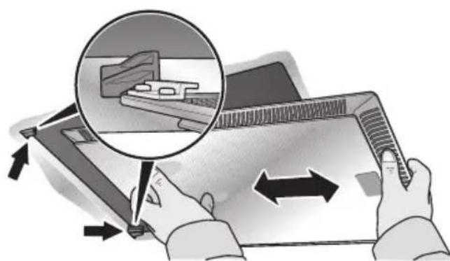
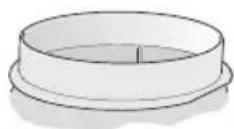
- Carefully remove the bulb ring with a suitable tool.
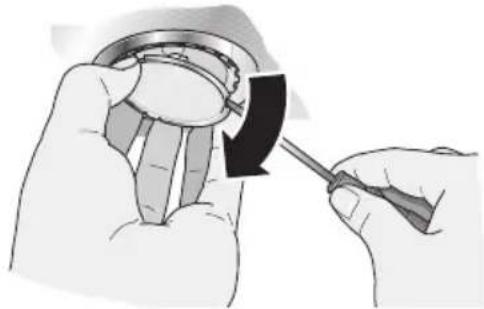
- Replace the defective bulb with a new one of the same type and equivalent power (see rating plate).
NOTE: When inserting halogen bulbs, do not touch the glass tube. Therefore use a clean cloth when inserting the bulb.
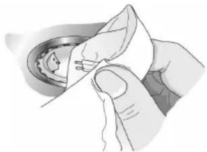
- Reinsert the bulb cover.
- Restore the power supply by inserting the mains plug or switching on the fuse.
Changing the filament bulbs
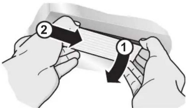
- Lift the bulb cover slightly.
- Push the bulb cover towards the middle of the appliance.
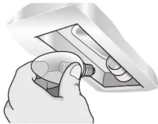
- Replace the defective bulb with a new one of the same type and equivalent power (see rating plate).
- Reinsert the bulb cover.
- Restore the power supply by inserting the mains plug or switching on the fuse.
NOTE: If the light does not function, check whether the bulbs have been inserted correctly.
Defective bulbs should be replaced immediately to avoid overloading the remaining bulbs.
Prior to installation, always follow the instructions and warnings in the chapter entitled "Safety instructions"!
Exhaust-air mode
The exhaust air is conveyed upwards via a ventilation shaft or directly through the outer wall to the exterior.
NOTE: The exhaust air must not be conveyed into a functioning smoke or exhaust gas flue or into a shaft which is used to ventilate installation rooms which contain heating appliances.
Before conveying the exhaust air into a non-functioning smoke or exhaust gas flue, obtain the consent of the appropriate heating engineer. Discharge exhaust air in accordance with the official and statutory regulations (e.g. regional building laws). If the exhaust air is conveyed through the outer wall, a telescopic wall box should be used.
- a short, straight exhaust air pipe and the largest possible pipe diameter. If pipe bends cannot be avoided, ensure the largest possible radii.
NOTE: If long, rough exhaust air pipes, a lot of pipe bends or pipe diameters less than 150 mm are used, the air capacity will be less than optimum and there will be an increase in noise.
Use only pipes or hoses made of non-combustible material for installation of the exhaust air duct. The manufacturer of the extractor hoods is not responsible for complaints which can be attributed to planning and design of the pipework.
Connecting pipes
The diameter of the exhaust air pipes should not be less than 150 mm. Round pipes:
We recommend an inner diameter of 150 mm, however at least 120 mm.
Flat ducts must have the same inner cross-section as round pipes.
There should be no sharp bends.
∅ 150 mm approx. 177 cm² ∅ 120 mm approx. 113 cm²
If pipe diameters differ:
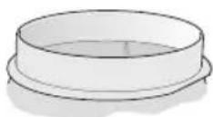
Use sealing strips.
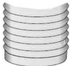
Connection of 150 mm ∅ exhaust air pipe (recommended size)
Attach exhaust air pipe directly to the air-pipe connector and seal appropriately. If using an aluminium pipe, smooth the connection area beforehand.
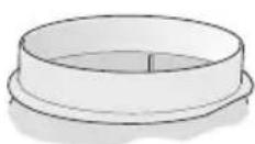
Connection of 120 mm ∅ exhaust air pipe
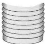
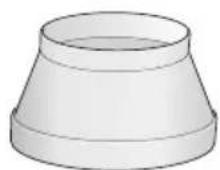
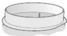
Attach reducing connector directly to the air-pipe connector. Attach exhaust air pipe to the reducing connector. Seal both joints appropriately.
ELECTRICAL CONNECTION
Before connecting the appliance to the power supply, always follow the instructions and warnings in the chapter entitled "Safety instructions"! The extractor hood may only be connected by a qualified electrician who is familiar with the regulations of the relevant electricity supply company.
RISK OF INJURY
If the power cord of the extractor hood is damaged, it must be replaced by the manufacturer, its customer service, or a similarly qualified person to prevent hazardous situations.
The extractor hood may be connected to a correctly installed earthed socket only. Attach the earthed socket as directly as possible behind the flue duct.
- The earthed socket should be connected via its own circuit.
- If the earthed socket is no longer accessible following installation of the extractor hood, a disconnector must be fitted as for a permanent connection.
If a permanent connection is required
A disconnector must be provided on the installation side. Switches with a contact opening of more than 3 mm and all-pole disconnection are regarded as disconnectors. This includes LS switches, fuses, and contactors.
Electrical specifications
The required connection data can be found on the rating plate inside the appliance when the grease filters have been removed.
Length of the power cord: approx. 1.30 m.
This extractor hood complies with the EC interference suppression regulations.
The extractor hood is designed for installation on the kitchen ceiling or on a rigid suspended ceiling.
During installation, optional accessories may also require fitting. Observe the minimum distance between hob and extractor hood (see "Safety instructions")! Avoid damaging the sensitive surfaces!
Preparing the ceiling
The ceiling must be level and horizontal. The enclosed screws and wall plugs are suitable for concrete and natural stone. Use the appropriate fasteners for other ceiling structures.
Ensure that the ceiling has adequate load bearing capacity.
Ensure that the wall plugs are secure.
Max. weight in kg: 43
Design is subject to modification in line with technical development.
Installing the upper support frame
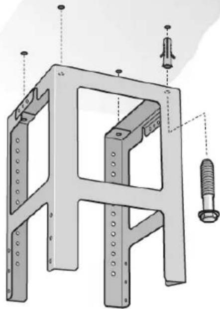
- Specify the total height of the support frame before installation and mark the screw holes. The height of the support frame can be adjusted in 20 mm steps.
The total height is measured from the height of the ceiling, the height of the worktop and the corresponding distances between the hob and extractor hood.
- On the ceiling mark the centre point of the extractor hood.
- Using the enclosed template, mark the positions for the screws on the ceiling.
4x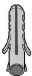
4x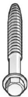
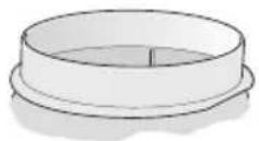
- Drill 4x 8 ∅ mm holes and press in wall plugs flush with the ceiling.
- Attach the upper part of the support frame to the ceiling with 4 screws.
- Ensure that the support frame is in the correct position. The middle bracket defines the preferred side. It must be facing the hob control.
Installing the lower support frame
Attach upper and lower parts of the support frame at the specified total height with 10 screws (preferred hole selection, see diagram).
Ensure that the lower support frame is in the correct position. The open side must be facing the hob control.
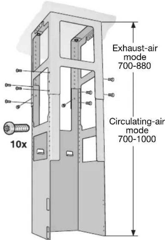
NOTE: The support frame can be aligned subsequently by loosening the fastening screws on the ceiling.
- Hook the extractor hood from below into the support frame.
Do not trap the power cord!
- Attach the extractor hood to the support frame with 2 securing screws.
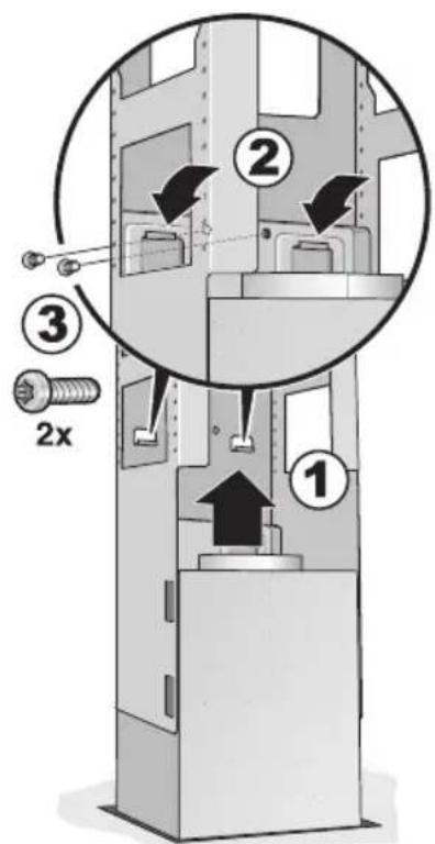
- Hook in retaining clip and screw tight.
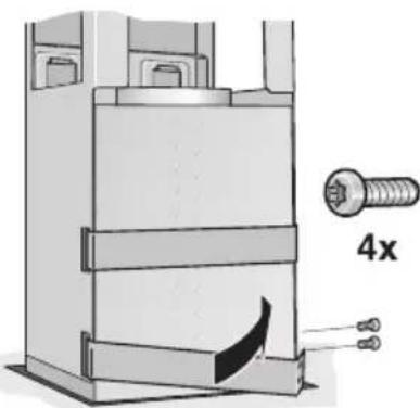
- Connect the pipes.
- Connect the power supply.
Installing the flue ducts
RISK OF INJURY
The insides of the flue ducts may have sharp edges. We recommend wearing protective gloves during installation.
- Separate the flue ducts. To do this, remove the adhesive tape.
- Remove the protective film from both flue ducts.
- Attach both parts of the upper flue to the extractor hood and push together.
NOTE: Protect the extractor hood from damage. Avoid scratching the sensitive surfaces.
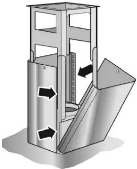
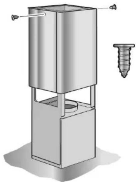
- Push up the upper flue part and secure with 2 screws.
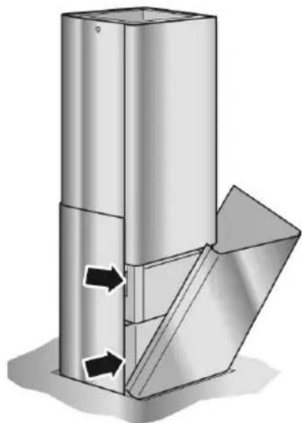
- Insert the two lower parts of the flue and push together.
FIRE HAZARD
4x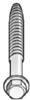
Table of contents
⚠️ FIRE HAZARD
4x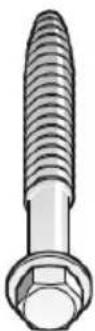
⚠ FIRE HAZARD
4x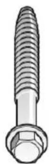
Contents
⚠️ FIRE HAZARD
4x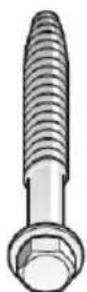
 | Z5134X5 |
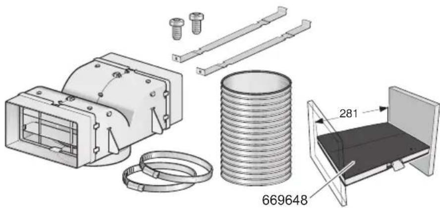 | Z5136X5 |
Online shop: www.neff-eshop.com