
BCH 120L - Boiler Ariston Thermo - Free user manual and instructions
Find the device manual for free BCH 120L Ariston Thermo in PDF.
| Product type | Storage water heater with coil heat exchanger |
| Capacity | 120 liters |
| Height | 880 mm |
| Diameter | 560 mm |
| Empty weight | 45 kg |
| Maximum operating pressure | 7 bar |
| Maximum storage temperature | 90 °C |
| Coil surface area | 0.7 m² |
| Heat exchanger power | 25 kW |
| Heating time | 21 min |
| Nominal continuous flow (ΔT=30°C) | 717 L/h |
| Nominal continuous flow (ΔT=45°C) | 478 L/h |
| Coil pressure drop | 40 mbar |
| Heat loss | 1.4 kWh/24h |
| Insulation | Polyurethane (PU) |
| Anti-corrosion protection | Protech electronic with titanium electrode |
| Power supply (Protech) | 230 V ~ 50 Hz |
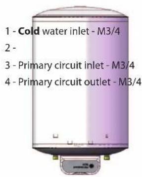
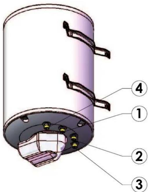
| Connections | Cold water inlet M3/4, Hot water outlet M3/4, Primary inlet M3/4, Primary outlet M3/4 |
| Installation | Wall-mounted or floor-standing (kits included) |
| Tank material | Enamelled steel at 850 °C |
| Warranty | Subject to professional installation conditions |
Frequently Asked Questions - BCH 120L Ariston Thermo
User questions about BCH 120L Ariston Thermo
0 question about this device. Answer the ones you know or ask your own.
Ask a new question about this device
Download the instructions for your Boiler in PDF format for free! Find your manual BCH 120L - Ariston Thermo and take your electronic device back in hand. On this page are published all the documents necessary for the use of your device. BCH 120L by Ariston Thermo.
USER MANUAL BCH 120L Ariston Thermo
Technical Installation Instructions and User Guide
- Directive EMC 2004/108/CE
EN 61000-3-2
EN 61000-3
EN 55014-1
Panier barre 2002/96
NORMES GENÉRALES DE SECURITÉ
Legendedeusymboles:
Position Stable Position Murale
GENERALITES

Position stable
Position murale
Transport, Storage and Recycling Instructions 17
General recommendatons 17
Declaration of conformity 17
Conformity of design and production 17
Electrical conformity Labelling. 17
General safety standards 18
GB
Technical description 19
Technical data 19
Appliance technical specifications 19
Dimensional characteristics 20
General points 21
Installation 21
Installation instructions 21
Recommended installation space 21
Safety assembly 22
Water connection and preliminary operations 22
Connection diagram 24
Installation options. 25
Installation kit 25
Accessories 25
Starting Up 26
Operation 26
Protech 27
Note for the installer 27
Diagnosing electronic circuit failure 27
Cabling diagram 28
Care and Maintenance 28
Exterior cleaning 28
Draining 28
Remove limescale 28
Limit of warranty 29
Notes 88
TRANSPORT, STORAGE AND RECYCLING INSTRUCTIONS
- The unit must be transported according to the pictograms on the packaging.
- The unit must be transported and stored in dry conditions and freezing conditions must be avoided.
- EU directive 2002/96/EC requires selective collection and recycling of used electric and electronic
devices.
- The "rubbish bin with a cross" symbol on the device indicates that the product must be disposed of separately from standard household waste at the end of its useful life, and must be brought to a waste sorting centre for electrical and electronic devices or returned to the seller when a replacement unit is purchased.
- Selective sorting, which allows a unit to be recycled at the end of its useful life and processed in a manner that respects the environment, helps to avoid potentially harmful effects on the environment and promotes recycling of the components that make up the product.
To find out more about existing waste collection centres, check with your local waste collection service or the store where you purchased your unit. - The packaging protects your water heater from damage during transport. We use materials selected for the purposes of environmental protection.
We request that you return these materials to your nearest recycling or waste collection centre.
If the unit comes with rechargeable batteries, these must be removed before the unit is discarded, and must be disposed of in a safe way.
These batteries must be removed from their housing, which is accessible under the plastic cover.
GENERAL RECOMMENDATIONS
The instructions are an integral part of the product, and must be provided to the user. Read the warnings with the instructions carefully, as they contain important information concerning safe installation, use and maintenance.
Keep the instructions safe so they can be referred to at a later date. This appliance is designed to supply and store hot water.
Consequently, it must be attached to a domestic heating installation and to hydraulic piping suitable for its levels of power and performance.
This unit must not be used for any other purpose; the manufacturer is released from all liability if any damage is due to incorrect or unreasonable installation.
Packaging waste must be disposed of in accordance with current standards and as soon as possible where it constitutes a potential danger, particularly to children.
To clean the exterior of the unit, it is recommended to use a damp cloth and cleaning products intended for this purpose. The use of abrasive products or solvents is strongly discouraged.
Only a highly qualified technician is authorised to carry out installation, which must meet current standards, otherwise the product warranty will become void. A badly installed unit can cause both tangible and intangible damage. In this case, the manufacturer is released from all liability.
If any accessories are installed on the unit, they must only be original parts from the manufacturer.
Before carrying out any repair and/or maintenance operation on the unit, it is important to isolate all supply sources.
In case of a malfunction in the unit, switch it off and phone technical assistance.
DECLARATION OF CONFORMITY
Conformity of design and production
This product conforms to EU directive 97/23CE, article 3, paragraph 3 concerning pressure equipment and 93/69/CEE relating to the EN12897 standard, specific to indirectly heated, unvented water heaters.
Electrical conformity Labelling
This product conforms to the following EU directives and standards:
LVD Directive (electrical safety) 2006/95/CE
EN 60335-1
EN 60335-2-21
EN 50366
-EMC Directive 2004/108/CE
EN 61000-3-2
EN 61000-3
EN 55014-1
Crossed-out basket 2002/96
GENERAL SAFETY STANDARDS
Legend of symbols:
Ignoring the warning may pose a risk of fatal injury to persons in some circumstances.
Ignoring the warning pay pose a risk of serious damage in some circumstances to objects, plants or animals.
1 - Avoid carrying out any operation that requires the unit to be opened.
Fulguration can occur through contact with live components. Burn injuries from hot components or injuries caused by parts that stick out or by sharp edges.
2 - Avoid carrying out any operation that requires the unit to be set down.
Fulguration can occur through contact with live components.
Flooding can be caused by water from tubing which has come loose.
3 - Avoid using the supply cable plug to connect or disconnect the unit.
Fulguration can be caused by a damaged cable, socket or plug. 4 - Avoid damaging the electrical supply cable.
Fulguration can be caused by exposed live wires. 5 - Avoid placing items on the unit.
Injuries can be caused by the item falling because of vibrations.
Damage may be caused to the unit or items below it by items that fall because of the vibrations.
6 - Do not climb on the unit.
Injury can be caused by the unit falling over.
Damage may be caused to the unit or items below it by the unit coming loose from its support.
7 - Avoid climbing on chairs, stepladders, ladders or unstable items to clean the unit.
Injury can be caused by falling from a height or by cuts (folding ladder).
8 - Do not attempt to clean the unit without having first shut it down, unplugged it or turned off the switch.
Fulguration can occur through contact with live components. 9 - Install the unit on a solid wall that will not be damaged by vibrations.
Noisy operation.
10 - Avoid damaging existing cables or tubing when drilling into the wall.
Fulguration can occur through contact with live conductors. Ex
plosions, fires or intoxication can occur because of gas escaping from damaged tubing.
Existing systems may be damaged. Flooding can be caused by water coming from damaged tubing.
11 - Protect tubing and linking cables to prevent them being damaged.
Fulguration can occur through contact with live components.
Flooding can be caused by water from tubing which has come loose.
12 - Make sure that the other systems linked to the unit meet the current applicable standards.
Fulguration can occur through contact with live conductors that have been incorrectly installed.
The unit may be damaged because of poor operating conditions.
13 - Use devices and manual tools that are intended for it (be sure that the tool is not worn out and that the handle is well attached), use them properly and take the precautions necessary to prevent them falling, and be sure to put them away after use.
Personal injury can be caused by projected shards or fragments, inhaling dust, being hit, or cuts, pricks or abrasions.
The unit may be damaged by nearby objects, projected shards, blows or cuts.
14 - Use the correct electrical tools (in particular, make sure that the cable and the supply socket are in good condition and that rotating or alternating parts are correctly attached), use them in the correct way, avoid obstruction by leaving the supply cable visible, attach them securely so that
they do not fall from a height, remove them and put them away after use.
Personal injury can be caused by projected shards or fragments, inhaling dust, being hit, or cuts, pricks or abrasions.
The unit may be damaged by nearby objects, shards being projected, blows or cuts.
15 - Make sure that portable ladders are stable, strong enough, that their steps are in good condition and not slippery, and there is someone monitoring them to make sure that they are not moved when there is somebody on them.
Injury can be caused by falling from a height or by cuts (folding ladder).
16 - Make sure that extending ladders are stable, strong enough, that their steps are in good condition and not slippery, that they have support bars the length of the ramp and on the platform.
Injury can be caused by falling from a height.
17 - Be sure that when work is carried out at a height (over 2 metres) that support bars have been placed around the working area, or that individual safety harnesses are used to prevent the risk of falling; in case a fall does happen, make sure that there are no dangerous obstacles in the way and that the landing is softened by a soft or pliable surface.
Injury can be caused by falling from a height.
18 - Make sure that the conditions of the working area are safe and healthy in terms of lighting, air flow, structural soundness and emergency exits.
Personal injury can be caused by blows, tripping and wounds.
19 - While work is being carried out, safety garments and equipment should be used.
Personal injury can be caused by electrocution, projected shards or fragments, inhaling dust, being hit, or cuts, pricks, abrasions, noise or vibrations.
20 - Internal operations must be performed with the greatest care, avoiding any rough contact with sharp points.
Personal injury can be caused by cuts, pricks and abrasions.
21 - Do not use insecticides, solvents or harsh cleaning products for unit maintenance.
Painted or plastic parts can be damaged.
22 - Do not use the unit for anything other than normal domestic use.
The unit may be damaged by operation overload.
There may be damage to objects handled in an improper way.
23 - Do not allow children or inexperienced persons to use the unit.
Damage to the unit may be caused by improper use.
24 - Use the correct size conductors for electrical connections.
Fire can be caused by overheating due to the electrical current passing through cables that are too small.
25 - Protect the unit and the areas adjacent to the work area using suitable materials.
The unit or nearby objects may be damaged by shards being projected or sharp implements.
26 - Move the unit using adequate protective measures and the greatest care.
Damage can be caused to the device or nearby objects from blows, cuts or crushing.
27 - Make sure that materials and equipment are kept to make unit maintenance easier and safer, avoid piling objects that can fall over.
Damage can be caused to the device or nearby objects from blows, cuts or crushing.
28 - Restore the safety and control procedures that indicate the need for operations on the unit, and make sure that they are being carried out correctly before it is put back in service.
Damage or harm to the unit can be caused by it operating wi - thout controls in place.
TECHNICAL DESCRIPTION
Technical Data
| BCH 80 L 120 L 160 L 200 L | |||||
| Capacity Ltr 80 120 160 200 | |||||
| Coil surface | m² | 0,5 0,7 0,7 1 | |||
| Power Kw 21,3 25 25 29 | |||||
| Heating time | Min 17 2 | 29 31 | |||
| Nominal flow rate | |||||
| Outlet flow rate with ΔT = 30°C | L/h | 611 717 7 | 17 831 | ||
| Outlet flow rate with ΔT = 45°C | L/h | 407 478 4 | 78 554 | ||
| Coil resistance | mbar | 30 40 40 | 45 | ||
| Max. working pressure | bar | 7 | 7 | 7 | 7 |
| Thermal loss | kWh/24 h | 1,3 1,4 1,6 2,1 | |||
| Maximum temperature | °C | 90 90 90 | 90 | ||
| Weight | Kg 34 45 | 51 62 | |||
| Insulation | PU | PU | PU | PU | |
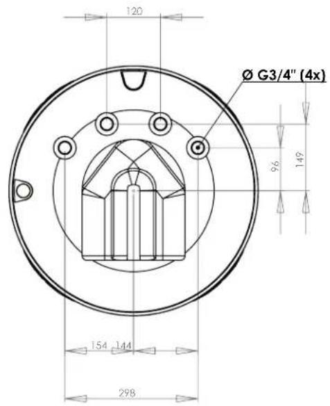
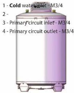
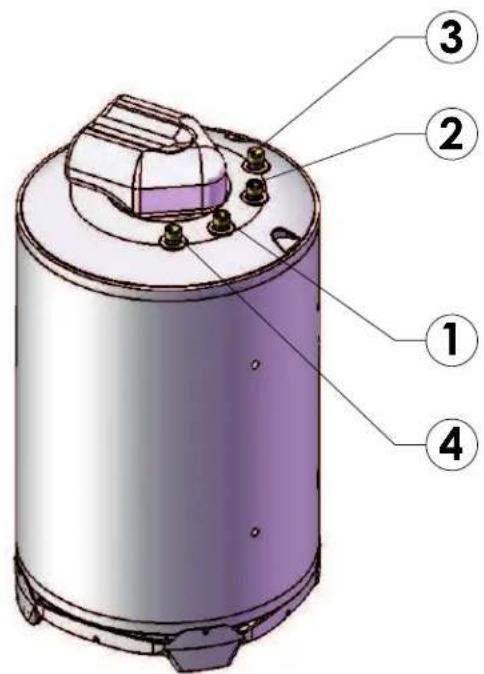
Appliance technical specifications
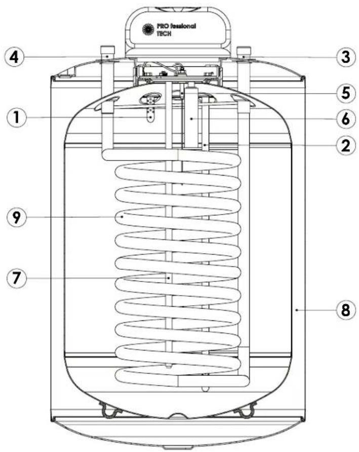
Legend:
- Cold water inlet/hot water usage point (following direction of installation),
- Cold water inlet/hot water usage point (following direction of installation),
- Primary inlet/Primary outlet (following direction of installation),
- Primary inlet/Primary outlet (following direction of installation),
- Protech System (protection against corrosion),
- Magnesium Startup Anode,
- Temperature sensor,
- Polyurethane insulation,
- Coil Exchanger.
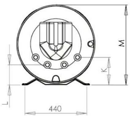
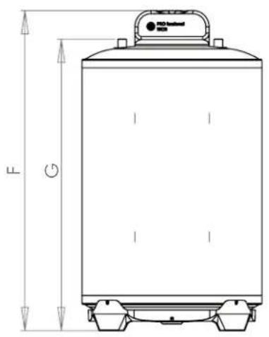
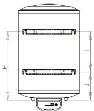
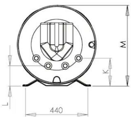
Dimensional characteristics
Water heater: mm
GB
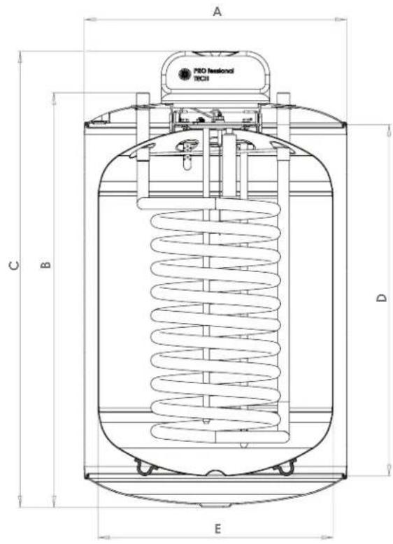
| BCH 80L BCH I 120 L BCH 160 L BCH 200 L | ||
| A 560 560 560 560 | ||
| B 670 880 1090 1310 | ||
| C 757 967 1177 1397 | ||
| D 535 745 955 1175 | ||
| E 500 500 500 500 | ||
| F 778 988 1198 1418 | ||
| G 690 900 1110 1330 | ||
| H 417,5 627,5 827,5 1027,5 | ||
| I 155 365 565 765 | ||
| J 262,5 262,5 262,5 262,5 | ||
| K 198 198 198 198 | ||
| L 145 145 145 145 | ||
| M 572 572 572 |
Stable position Wall position
GENERAL POINTS
The water heater with smooth-tube heat exchanger can be connected to each gas or oil furnace. The position of the heat exchangers provides complete heating of the water in the accumulator.
The tank is protected by an enamel covering giving protection up to 850^ , in accordance with the requirements of DIN 4753.
The water heater must be installed by an approved installer, in an area that is protected against freezing. Enamelled tanks are suitable for normal domestic hot water and approved for mixed setups (copper tubing, zinc tubing).
Unused connections must be blocked. The directives in force and the instructions from the local water service as well as DIN standards must be followed.
The tank is linked to the hydraulic distribution network via a cold water connection and to usage points via a hot water connection.
If hot water is taken from a usage point, cold water then enters the reservoir where it is heated to the temperature set using the thermostat (not provided with the product).
It is advisable to maintain the water temperature between 60^ and 65^, as this guarantees the best performance for the unit and ensures the following:
Maximum level of hygiene,
Maximum limit for thermal loss,
- Limiting the formation of limescale deposits.
INSTALLATION
Installation instructions
ONLY HIGHLY QUALIFIED PERSONNEL ARE AUTHORISED TO PERFORM THIS OPERATION, OTHERWISE THE WARRANTY WILL BECOME VOID
The information given below determines the validity of the warranty.
- The installation must:
a. Be installed by a qualified installer. You must conform to current national standards. It is necessary to respect
the instructions for the water heater,
b. Provide, when necessary, a pressure reducer for inlet water,
c. The system is required to have a safety assembly (maximum calibration: 7 bar) which must be installed
with the unit in a location where there is no possibility of freezing.
- The storage temperature must remain below 90^ .
- To prevent corrosion, it is necessary to regularly check the charge level of the battery that supplies the protech spark plug and replace it if there is a fault.
- In case of installation in a location above a living area (roof space, attics, suspended ceilings, etc.), insulate the pipes and provide a holding tank with water evacuation. In all cases, a connection to mains drainage is necessary.
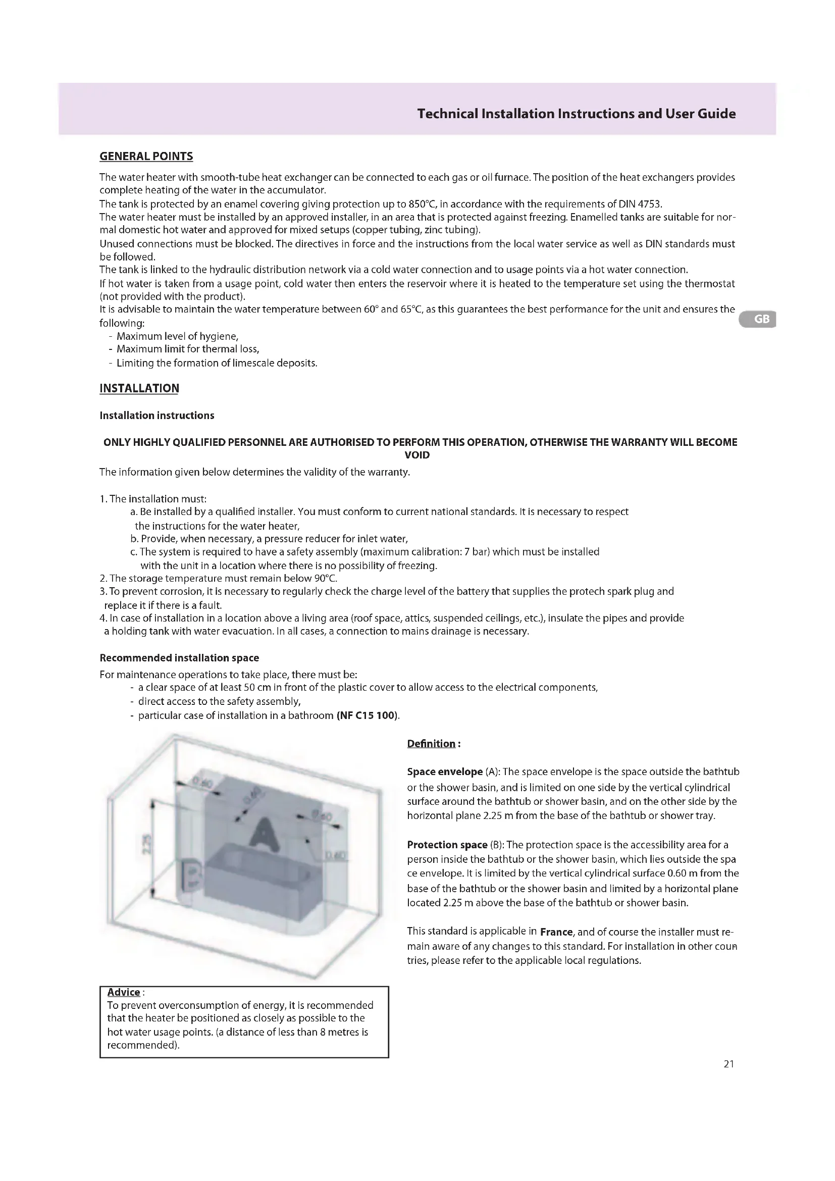
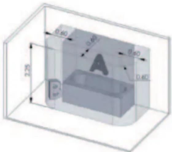
Recommended installation space
For maintenance operations to take place, there must be:
- a clear space of at least 50~cm in front of the plastic cover to allow access to the electrical components,
- direct access to the safety assembly,
- particular case of installation in a bathroom (NF C15 100).
Advice:
To prevent overconsumption of energy, it is recommended that the heater be positioned as closely as possible to the hot water usage points. (a distance of less than 8 metres is recommended).
Definition:
Space envelope (A): The space envelope is the space outside the bathtub or the shower basin, and is limited on one side by the vertical cylindrical surface around the bathtub or shower basin, and on the other side by the horizontal plane 2.25m from the base of the bathtub or shower tray.
Protection space (B): The protection space is the accessibility area for a person inside the bathtub or the shower basin, which lies outside the space envelope. It is limited by the vertical cylindrical surface 0.60m from the base of the bathtub or the shower basin and limited by a horizontal plane located 2.25m above the base of the bathtub or shower basin.
This standard is applicable in France, and of course the installer must remain aware of any changes to this standard. For installation in other countries, please refer to the applicable local regulations.
Safety assembly
The unit must be installed with a safety assembly that meets current national and EU standards, connected to the cold water inlet tube and suitable for the maximum working pressure indicated on the technical label.
It is advisable to use a safety assembly with a membrane.
The safety assembly must be installed as close as possible to the cold water inlet and the water flow must not be obstructed by other accessories.
If, for technical reasons, the safety assembly cannot be installed with a direct link to the cold water inlet, a rigid link must be used.
GB
In any case, the link must be made using a material that is able to withstand the temperatures and pressures indicated on the technical label.
The outlet for the safety assembly should never be obstructed and should be linked to vertical evacuation tubes with a diameter at least as large as that of the unit's connections.
It is recommended that the safety assembly be installed as low down as possible so that the unit can be drained sufficiently.
If the supply pressure is greater than 4/5 bar, a pressure reducer must be installed upstream of the safety assembly.
It is recommended that a stop valve be positioned upstream of the safety assembly.
Always use new connection piping to make connections to a water supply network, never install used pipes. These pipes must also conform to the EN 61770 standard.
Water connection and preliminary operations
- Verify that the useful thermal power from the generator exceeds the power that the tank can absorb by more than 15% .
- Verify that the volumes and the pre-charge pressure of the secondary circuit expansion reservoir are suitable for the system.
- If the water in the circuit is excessively hard, install (upstream of the tank), a correctly adjusted water softener.
- If impurities are found in the water in the circuit, install a suitable filter, making sure that the circulators have sufficient flow and a sufficient extractor and that they rotate regularly.
- Verify that the thermostat sensor is correctly positioned.
- Verify that the thermostat controls are functioning correctly.
- Install a safety assembly that meets current national and EU standards, and which is suitable for the maximum working pressure indicated on the product identification label.
The DOMESTIC WATER INSTALLATION must be connected in the following way:
FLOOR POSITION
(With special kit)
1 - Secure the base of the product with the 4 screws provided in the kit.
2-Connect the unit following the instructions indicated on the diagram:
Domestic hot water outlet - M3/4
GB
WALL POSITION
(With special kit)
1 - Remove the 4 screws + washers on the back of the unit.
2 - Install the two wall supports and secure them with the 4 screws provided in the kit.
3 - Secure the unit to the wall.
4 - Affix the Pro-Tech label provided in the kit.
5 - Connect the unit following the instructions indicated on the diagram:
Domestic hot water outlet - M3/4
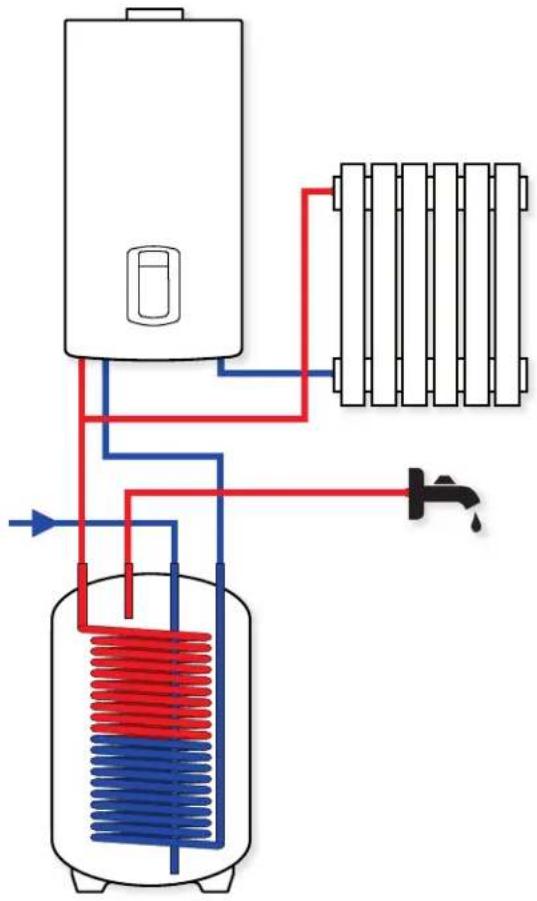
Connection diagram
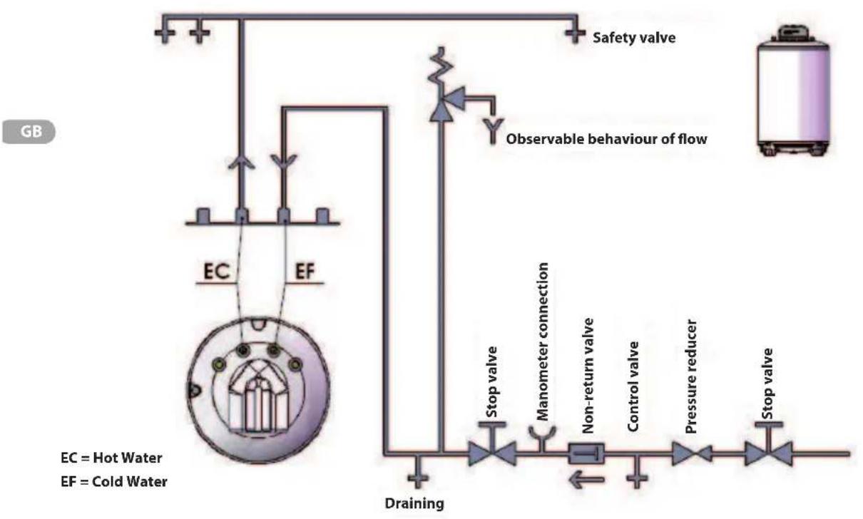
Stable position
Wall position
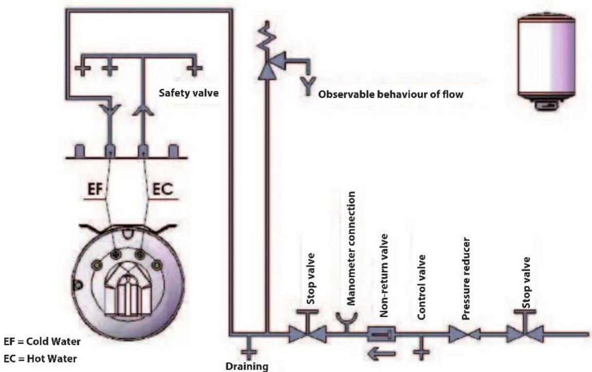
EF = Cold Water
EC = Hot Water
Installation options
In case of an installation with a connection to a boiler.
This unit can be connected to a domestic installation that uses a boiler as its energy source.
With a connection kit made up of: 7-bar safety assembly + siphon + PVC discharge hose for 4L domestic expansion vessel. Boiler-tank connection using stainless steel extendible hoses + solder sleeves.
Method for connecting a boiler to a stable BCH tank :
Installation kit:
- Wall attachment kit
- Stability kit (positioned on the floor)
Accessories:
- an additional electric kit, sold separately, can be installed (see instructions in the kit) on this unit.
-Tripod kit 0560.
STARTING UP
For domestic water use, fill the accumulator with cold water and remove the air from the circuit by opening a valve to decant the hot water.
Fill the primary circuit's hot water exchanger and remove the air from the unit.
Set the temperature for domestic hot water in the tank by adjusting the thermostat (not provided with the unit).
It is strongly advised to maintain the temperature between 60^ and 65^
GB
Only a qualified technician is authorised to start up the unit.
Regularly check that all the control, regulation and testing devices are functioning properly.
OPERATION
This tank allows hot water to be provided easily, for domestic use as well as industrial use.
The tank is linked to the hydraulic distribution network via a cold water connection and to usage points via a hot water connection.
If hot water is taken from a usage point, cold water then enters the reservoir where it is heated to the temperature set using the thermostat (not provided with the product).
It is advisable to maintain the temperature between 60^ and 65^, as this guarantees the best performance for the unit and ensures the following:
Maximum level of hygiene,
Maximum limit for thermal loss,
- Limiting the formation of limescale deposits.
The water in the tank's reservoir is heated through inflow of the primary hot water that flows through the coil inside the unit.
Important:
- The unit must never be turned on when it is empty, as this risks damaging its electrical components.
- Never block the safety assembly opening.
PROTECH
The PROFESSIONAL TECH system, an exclusive solution, is an electronic system which protects against corrosion and ensures the maximum life of your water heating tank, even where water quality is poor.
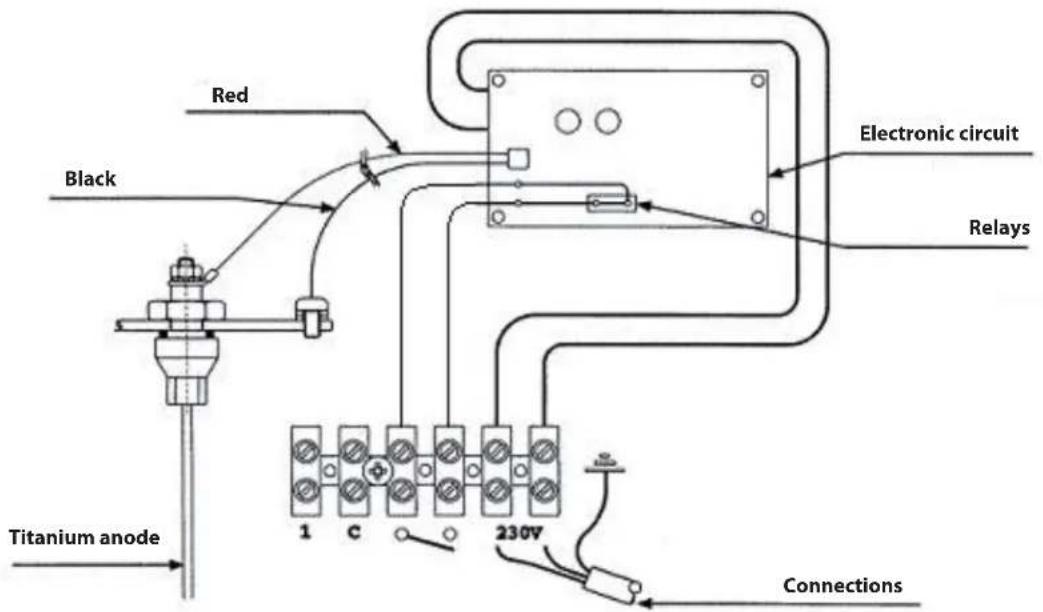
The electronic circuit allows a difference in potential to be created between the tank and the titanium electrode, in such a way as to guarantee optimum protection of the tank and prevent corrosion.
Optimum functioning of the protection system REQUIRES A PERMANENT CONNECTION TO A 230V SUPPLY, even when the hot water generator is not running. To be able to disconnect the protection system for longer than 2 hours without risking the length of the tank's useful life, it is essential to drain the tank beforehand!!
The electronic circuit is linked to the 230V network, and also to the tank being protected and the titanium protection electrode, as shown in the diagram on the following page.
Correct functioning of the protection system is indicated by the green indicator light coming on, which shows that the circuit terminals are live. In case of a fault, the red indicator light will signal that there is a short circuit between the electrode and the tank, that one of the cables (tank or electrode) is detached, or that there is no water in the tank.
Therefore, your hot water generator is correctly protected if the green indicator light is on and the red light is off. If this is not the case, please call your installer.
Note for the installer
Important: do not carry out any operation without having first cut the electricity supply from the 230V network, (as this is a quick operation, it can be carried out without first draining the tank and not necessarily cause corrosion).
The electronic circuit can be replaced very easily, without draining the tank, by:
- Unplugging the two supply lines that lead from the electronic circuit to the supply terminal block,
- Unplugging the quick connector with polarising slot that links the circuit to the tank and the electrode,
- Detaching the electronic circuit from its support (plastic clips in the 4 corners),
- To replace a defective circuit with a new one, perform the above steps in reverse order.
Diagnosing electronic circuit failure
1) The GREEN light is not on:
-- Verify that the circuit supply line is plugged in (if not, plug it in),
- Check that the electronic circuit is being supplied (if not, replace the supply cable),
- Verify that the power being supplied is 230V (if not, supply 230V),
- If all the above have been verified and there is still a fault, replace the electronic circuit (installer).
2) The RED light is on:
- Verify that the tank is full of water (if not, fill it so that the following checks can be carried out),
- Verify that the quick connector is properly positioned (if not, correct this),
- Verify that the electrode connection cable (that enters the glove finger in the base) is properly connected (pull it gently from above to make sure it is connected) (if not, replace the base and its electrode),
- Verify that the tank connection cable is properly connected to the tank (if not, connect it correctly).
- Verify that the two cables coming from the quick connector are not damaged or stripped, etc. (if they are, replace the base and its electrode),
- If all the above have been verified and there is still a fault, replace the electronic circuit (installer).
Request the assistance of your installer.
Cabling diagram
IMPORTANT: THE ELECTRONIC CIRCUIT MUST ONLY OPERATE AT 230V!
CARE AND MAINTENANCE
THE CURRENT MUST BE CUT BEFORE ANY OPERATION IS CARRIED OUT ON THE UNIT
All operations must be carried out by a qualified technician.
We recommend subscribing to a maintenance contract and planning to replace the safety assembly at least every 5 years, if necessary. Every year (twice a year if the water is treated by a water softener), the unit must be drained so that the Protech anode can be checked to make sure it is functioning properly.
For these operations, contact your trusted installer.
Exterior cleaning
The external parts of the tank must be cleaned using a damp cloth and appropriate cleaning products that are available commercially. In any case, the use of abrasive products, solvents, spirits, alcohol, etc. is not recommended.
Draining
Unplug the water heater and the hydraulic supply.
Open the hot water valve to let air in.
Open the drainage valve on the safety assembly.
Remove limescale
In cases of very hard water, it is advisable to remove limescale at least twice a year.
To do this, it is first of all necessary to empty the hot water tank and then remove the upper flange to be able to access the interior. Carry out the task using a suction device and a plastic or wooden brush (to remove the most resistant sediment). Clean it again and rinse it with a spray of water.
While cleaning, be careful not to damage the enamel layer that protects the inside of the reservoir.
Replace the upper flange, install a new seal and fill the reservoir, making sure there are no leaks.
LIMIT OF WARRANTY
The warranty is only valid if a qualified technician carries out the installation.
The warranty does not cover faults due to:
Abnormal environmental conditions :
- positioning in a location that is affected by freezing or bad weather.
- supply with rainwater, well water, or water that displays particularly abnormal aggressiveness and does not conform to current national regulations and standards.
- the warranty is limited to the repair or replacement of units and components that were found to be defective from the start. If necessary, the part or the product may be returned to one of our factories, but only after the prior agreement of our technical services department. The user will be responsible for labour, freight, packaging and transport costs. Repair or exchange of a component in the unit can not in any case lead to compensation.
- various damage caused by bumps or drops during handling after delivery from the factory.
- in particular, water damage that could have been avoided by repairing the water heater immediately.
The warranty only applies to the water heater and its components and excludes all or any part of the electric or hydraulic installation of the unit.
- electrical supply where there are significantly high voltages (in cases where an electric kit has been installed).
An installation that does not conform to regulations, current national standards and best industry practice.
In particular:
- the absence or incorrect installation of the safety assembly.
- installation of a safety assembly that does not meet current national standards or use of a previously used safety assembly on a newly installed water heater.
- modifying the safety assembly settings after breaching the seal.
- abnormal corrosion due to incorrect hydraulic connections (direct iron-copper contact).
- defective electric connection that does not meet current national installation standards, earthed incorrectly, insufficient cable section, prescribed connection diagrams not being followed, etc. (in cases where an electric kit has been installed).
- powering the unit without filling it beforehand (dry heating).
Insufficient maintenance :
- abnormal scaling of the heating elements and the safety devices.
not maintaining the safety assembly that leads to overpressure (see instructions). - body subjected to external abuse.
- modifying original equipment without the consent of the manufacturer or using external parts that it has not referenced.
not maintaining the unit, in particular not replacing the anode soon enough (see "MAINTENANCE").
Recommendations
For areas with very hard water, the use of a water softener does not cause our warranty to become void as long as the water softener meets current industry regulations, and is checked and maintained regularly. In particular: the residual hardness must not be lower than 12^ .

- NORMES GENÉRALES DE SECURITÉ
- GENERALITES
- GB
- TRANSPORT, STORAGE AND RECYCLING INSTRUCTIONS
- GENERAL RECOMMENDATIONS
- DECLARATION OF CONFORMITY
- Conformity of design and production
- Electrical conformity Labelling
- GENERAL SAFETY STANDARDS
- TECHNICAL DESCRIPTION
- Technical Data
- Appliance technical specifications
- Legend:
- Dimensional characteristics
- GENERAL POINTS
- INSTALLATION
- Installation instructions
- ONLY HIGHLY QUALIFIED PERSONNEL ARE AUTHORISED TO PERFORM THIS OPERATION, OTHERWISE THE WARRANTY WILL BECOME VOID
- Recommended installation space
- Advice:
- Definition:
- Safety assembly
- Water connection and preliminary operations
- FLOOR POSITION
- WALL POSITION
- Installation kit:
- Accessories:
- STARTING UP
- OPERATION
- Important:
- PROTECH
- Note for the installer
- Diagnosing electronic circuit failure
- CARE AND MAINTENANCE
- THE CURRENT MUST BE CUT BEFORE ANY OPERATION IS CARRIED OUT ON THE UNIT
- Exterior cleaning
- Draining
- Remove limescale
- LIMIT OF WARRANTY
- Recommendations
Brand : Ariston Thermo
Model : BCH 120L
Category : Boiler