
KX400.4 - Car radio KICKER - Free user manual and instructions
Find the device manual for free KX400.4 KICKER in PDF.

| Product type | 4-channel amplifier |
| Brand | KICKER |
| Model | KX400.4 |
| RMS power (4Ω stereo) | 50 W x 4 @ 14.4V, ≤1% THD+N |
| RMS power (2Ω stereo) | 100 W x 4 @ 14.4V, ≤1% THD+N |
| RMS power (4Ω bridged) | 200 W x 2 @ 14.4V, ≤1% THD+N |
| Frequency response | 10 Hz - 20 kHz (±1 dB) |
| Signal-to-noise ratio | >95 dB (at rated power) |
| Built-in filters | High-pass, low-pass, band-pass (24 dB/octave) |
| Crossover frequency (Amp 1) | 10 - 500 Hz (x1) or 100 - 5,000 Hz (x10) |
| Crossover frequency (Amp 2) | High-pass: 10-500 Hz; Low-pass: 40-5,000 Hz (x10 possible) |
| Bass boost (KICK EQ) | 0 to 18 dB at 40 Hz |
| Input sensitivity | Low level: 125 mV - 5 V; High level: 250 mV - 10 V |
| Minimum impedance (stereo) | 2 Ω |
| Minimum impedance (bridged) | 4 Ω |
| Dimensions (L x H) | 28.4 x 5.5 cm (11 3/16 x 2 1/8 inches) |
| Power supply | 10 - 16 V DC (external fuse not included) |
| Startup modes | Remote turn-on (+12V), DC offset, audio detection |
| Protection | Thermal, short circuit, over/under voltage (PRT LED) |
| Inputs | 2 x differential RCA (low/high level) |
| Outputs | 4 speaker channels (screw terminals) |
| Gain control | Variable per channel (Amp 1 and 2) |
| Approximate weight | Approximately 2.5 kg (not specified, reasonable estimate) |
Frequently Asked Questions - KX400.4 KICKER
User questions about KX400.4 KICKER
0 question about this device. Answer the ones you know or ask your own.
Ask a new question about this device
Download the instructions for your Car radio in PDF format for free! Find your manual KX400.4 - KICKER and take your electronic device back in hand. On this page are published all the documents necessary for the use of your device. KX400.4 by KICKER.
USER MANUAL KX400.4 KICKER
KX 4-CHANNEL AMPLIFIER KX400.4
Owner's Manual | English
@ 14.4V, 4Ω stereo, ≤ 1% THD+N 50W × 4
@ 14.4V, 2Ω stereo, ≤ 1% THD+N 100W x 4
@ 14.4V, 4Ω bridged, ≤ 1% THD+N 200W × 2
Length | in. [cm] 11 3/16 [28.4]
Height | in. [cm] 2 1/8 [5.5]
Width | in. [cm] 8 5/16 [21]
Frequency Response ± 1dB 10Hz-20KHz
Signal-to-noise Ratio >95dB, A-weighted, re: rated power
Input Sensitivity Low Level: 125mV–5V
High Level: 250mV-10V
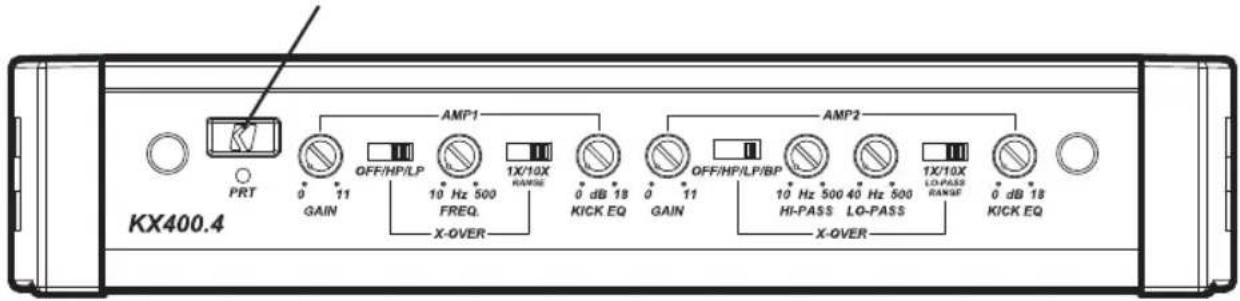
Electronic Crossover Amp 1: OFF/HP/LP; Variable 10-5,000Hz with X10 switch
Amp 2: OFF/HP/LP/BP; Variable HP, 10–500Hz;
Variable LP, 40-5,000Hz with 10X switch
Slope: 24dB/octave
KICK EQ Bass Boost Variable 0-18dB @ 40Hz
Pro Tip: To get the best performance from your new KICKER Amplifier and extend the warranty by 1 year, use genuine KICKER accessories and wiring.
INSTALLATION
Mounting: Choose a structurally sound location to mount your KICKER amplifier. Make sure there are no items behind the area where the screws will be driven. Choose a location that allows at least 4" (10cm) of open ventilation for the amplifier. If possible, mount the amplifier in the climate-controlled passenger compartment. Drill four holes using a 7/64" (3mm) bit and use the supplied #8 screws to mount the amplifier.
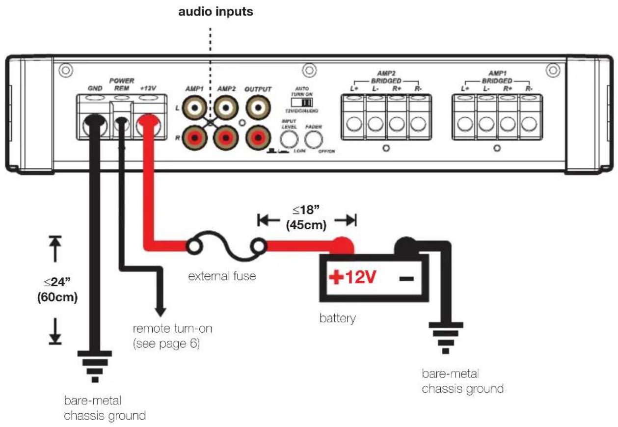
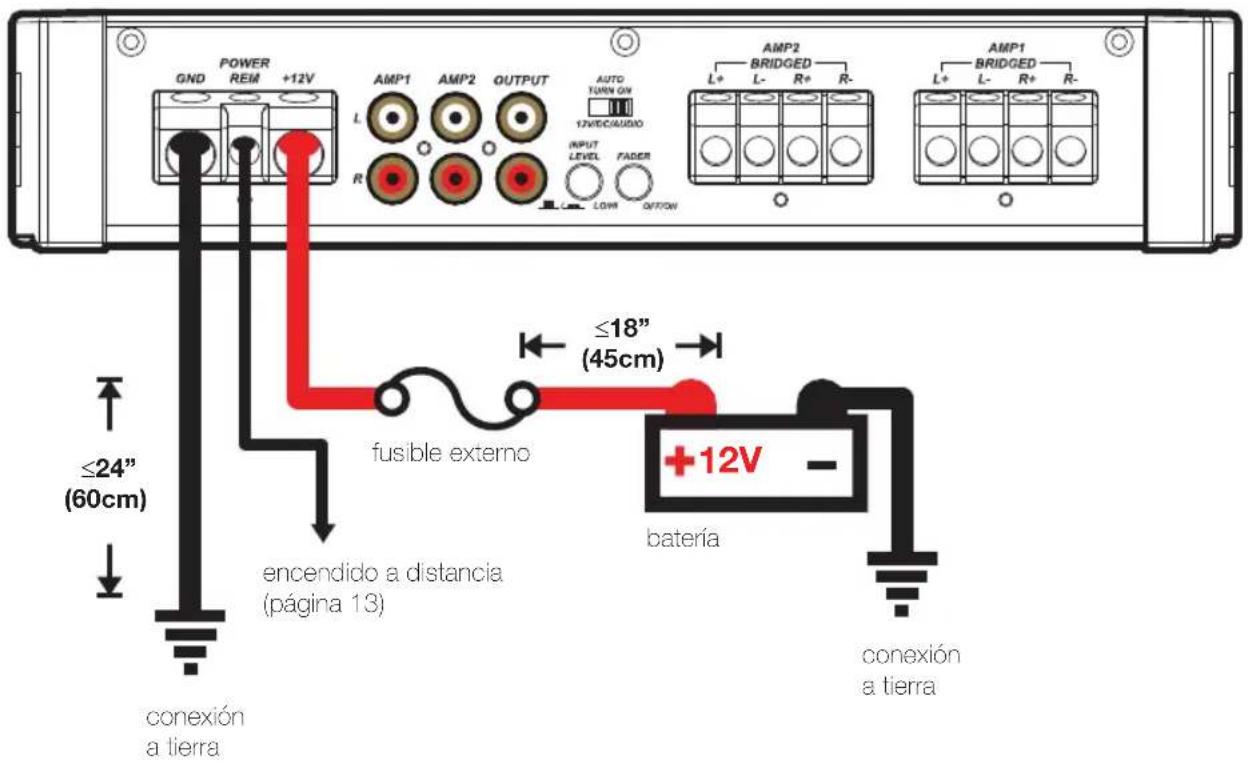
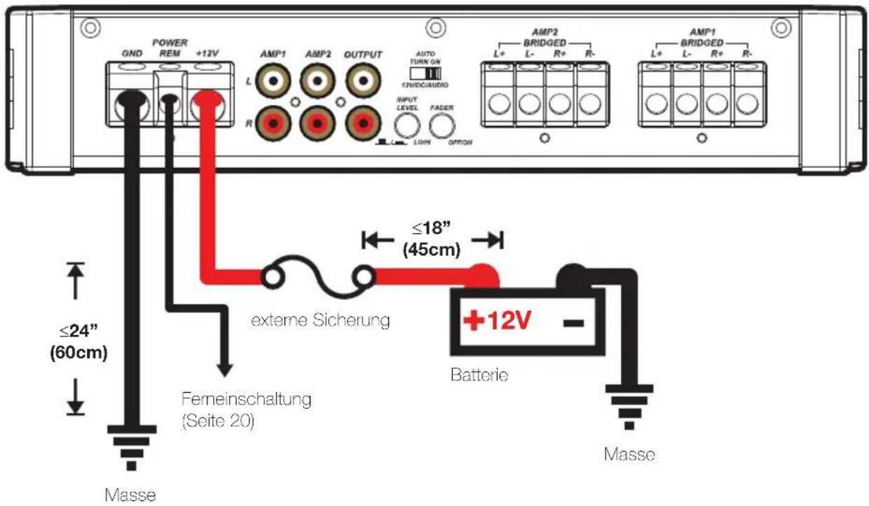
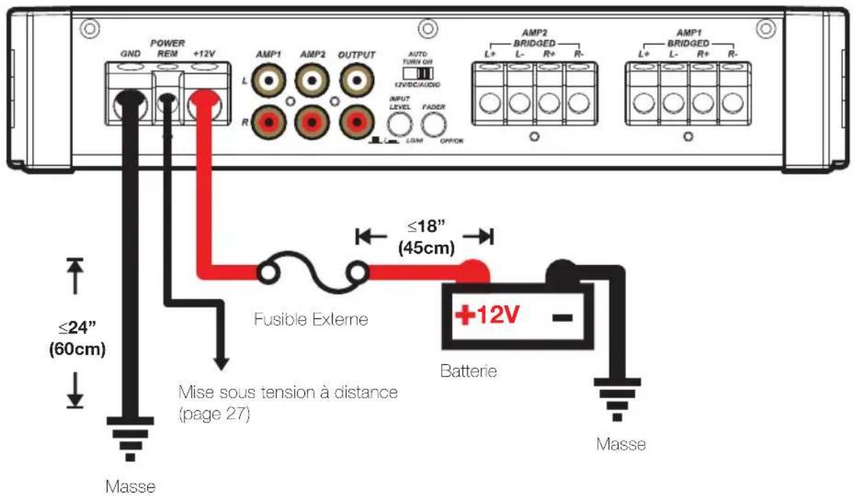
Wiring: Disconnect the vehicle's battery to avoid an electrical short. Then, connect the ground wire to the amplifier. Make the ground wire short, 24" (60cm) or less, and connect it to a paint-and-corrosion-free, solid, metal area of the vehicle's chassis. Adding an additional ground wire of this same gauge (or larger) between the battery's negative post and the vehicle chassis is recommended.
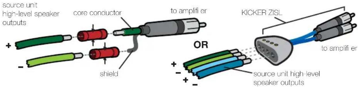
The KX amplifier has dual input sensitivity differential RCA inputs which will receive either high or low level signals from your car stereo's source unit. A high-level signal can be run from the source unit's speaker outputs to the stereo RCA input on the end panel of the amplifier using the KICKER ZISL as shown (make sure you set the KX amplifier's input level switch to "HI"). Alternatively, the signal can be delivered to the amplifier using the low-level RCA outputs on the source unit. Set the input level switch on the end panel of the amplifier to "LO". Keep the audio signal cable away from factory wiring harnesses and other power wiring. If you need to cross this wiring, cross it at a 90 degree angle.
Install a fuse within 18" (45cm) of the battery and in-line with the power cable connected to your amplifier. If you ever need to remove the amplifier from the vehicle after it has been installed, the ground wire should be the last wire disconnected from the amplifier--just the opposite as when you installed it.
Model External Fuse (sold separately)
Power/Ground Wire KICKER Wiring Kit
KX400.4 1 x 80 Ampere 4 Gauge PK4, CK44, ZCK44
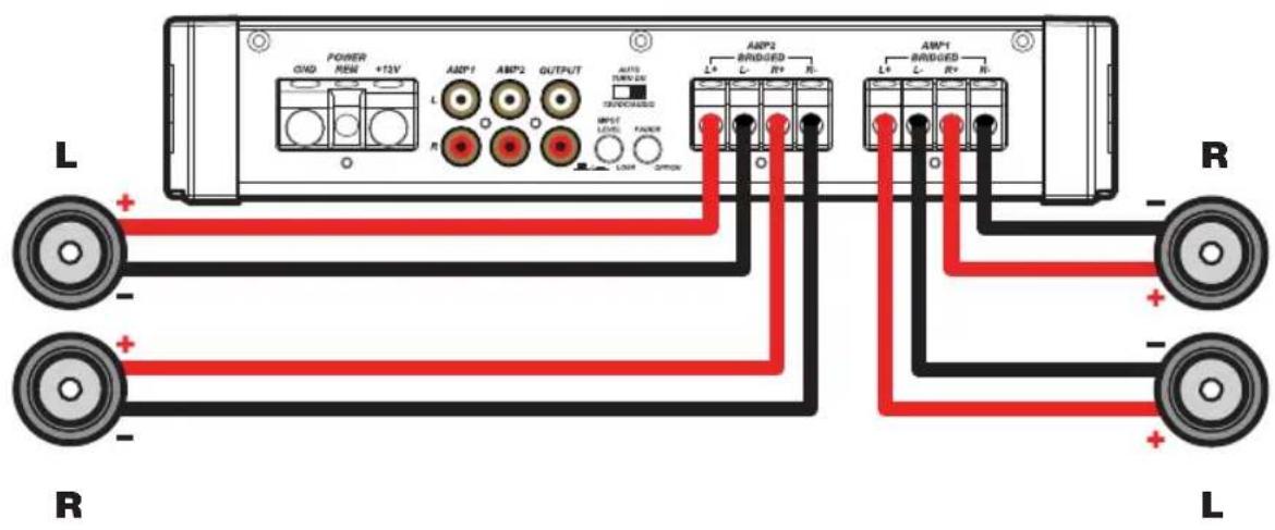
POWER WIRING
minimum impedance of 2 ohms per channel
4
minimum impedance of 4 ohms


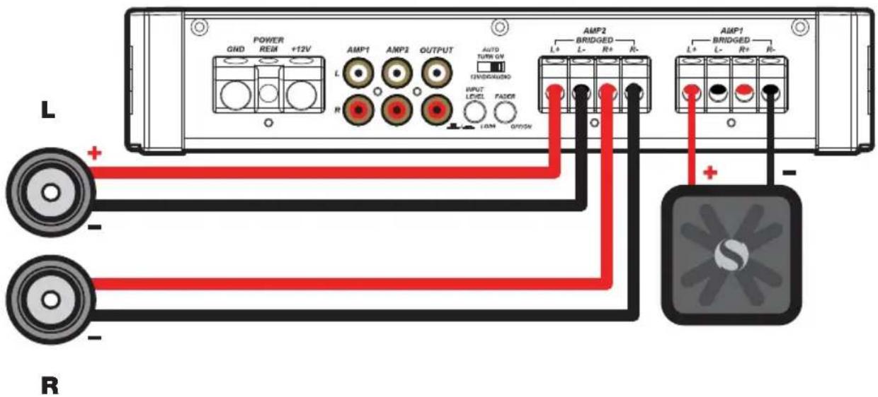
STEREO-AND-MONO-SIMULTANEOUSLY (SAMS) OPERATION
minimum impedance of 4 ohms bridged (mono) and 2 ohms per channel stereo
OPERATION
Mini-USB for internal use only; do NOT remove or tamper. KICKER is not responsible for any damage to equipment resulting from connections made to this port.
Automatic Turn-On Selection: The KX series offers three different automatic turn-on modes that can be selected on the end panel; +12V, DC Offset, and Audio. Using either the DC Offset or Audio mode causes the REM terminal to have +12V out for turning on additional amplifiers.
- Remote Turn-On: Set the switch to +12V to use the remote turn-on lead from your source unit. Run 18 gauge wire from the Remote Turn-On Lead on your source unit to the terminal labeled REM between the amplifier's positive and negative power terminals. This is the preferred automatic turn-on method.
- DC Offset Turn-On: If Remote Turn-On is not an option, the next best setting is DC Offset. The DC Offset mode detects a 6V DC offset from the HI-Level speaker outputs when the source unit has been turned on.
- Signal Sense Turn-On: The Audio setting is the final alternative for Automatic turn-on. This is a Signal Sense turn-on method that detects the incoming audio signal from your source unit and automatically turns on the amp. This turn-on method will not work properly if the input gain control is not set appropriately.
Input Level: The RCA inputs on KICKER KX amplifiers are capable of receiving either Hi or Low-level signals from your source unit. If the only output available from your source unit is a Hi-Level signal, simply press in the Input Level switch on the amplifier. Either input method will provide a low-level output signal at the RCA output, which effectively passes the audio signal to another amplifier or component. Refer to the wiring section of this manual for additional instructions.
Input Gain Control: The input gain control is not a volume control. It matches the output of the source unit to the input level of the amplifier. Turn the source unit up to about 3/4 volume (if the source unit goes to 30, turn it to 25). Next, slowly turn (clockwise) the gain on the amplifier up until you can hear audible distortion, then turn it down a little.
Crossover Switches with Frequency Multiplier: Use the XOVER switches on the end panel of the amplifier to set the internal crossovers of AMPS 1 & 2 to OFF, HI-PASS, LO-PASS, or BAND-PASS (AMP 2 only). When the switch is set to OFF, a full bandwidth signal will be amplified. Set the switch to HP if you want the amplifier's internal crossover to serve as a high-pass filter. Set the switch to LP if you want the amplifier's internal crossover to serve as a low-pass filter. Set the switch to BP when a specific frequency range is required. Never change the crossover switches with the audio system on!
Set the 1X/10X frequency multiplier switch to the setting that is appropriate for your application. A setting of 10X will set the range of the AMP 1 crossover to 100–5,000Hz, and the LO-PASS crossover of AMP 2 to 400–5,000Hz.
KICK EQ Bass Boost Control: The variable bass boost control on the side of the KX400.4 amplifier is designed to give you increased output, 0–18dB, at 40Hz. The setting for this control is subjective. If you turn it up, you must readjust the input gain control to avoid clipping the amplifier.
TROUBLESHOOTING
If your amplifier does not appear to be working, check the obvious things first such as blown fuses, poor or incorrect wiring connections, incorrect setting of crossover switch and gain controls, etc. There is a Protection (PRT) LED on the side panel of your KICKER KX series amplifier. Depending on the state of the amplifier and the vehicle's charging system, the LED will either glow red or be off.
Red (PRT) LED flickering with loud music? The red (PRT) LED indicates low battery voltage or an illegal load. Check all the connections in your vehicle's charging system. It may be necessary to replace or charge your vehicle's battery or replace your vehicle's alternator.
Red (PRT) LED on, no output? ① Amplifi er is very hot = thermal protection is engaged. Test for proper impedance at the speaker terminals with a VOM meter (see the diagrams in this manual for minimum recommended impedance and multiple speaker wiring suggestions). Also check for adequate airflow around the amplifi er. ② Amplifi er shuts down only while vehicle is running = voltage protection circuitry is engaged. Voltage to the amplifier is not within the 10–16 volt operating range. Have the vehicle's charging and electrical system inspected. ③ Amplifi er will only play at low volume levels = short circuit protection is engaged. Check for speaker wires shorted to each other or to the vehicle chassis. Check for damaged speakers or speaker(s) operating below the minimum recommended impedance.
No or low output? ① Check the balance control on source unit ② Check the RCA (or speaker input) and speaker output connections.
Alternator noise-whining sound with engine's RPM? ① Check for damaged RCA (or speaker input) cable ② Check the routing of RCA (or speaker input) cable ③ Check the source unit for proper grounding ④ Check the gain settings and turn them down if they are set too high.
Reduced bass response? Reverse a speaker connection from positive to negative on the stereo/subwoofer channel(s); if the bass improves, the speaker was out of phase.
Ground Noise? KICKER amplifiers are engineered to be fully compatible with all manufacturers' head units. Some head units may require additional grounding to prevent noise from entering the audio signal. If you are experiencing this problem with your head unit, in most cases running a ground wire from the RCA outputs on the head unit to the chassis will remedy this issue.
CAUTION: When jump starting the vehicle, be sure that connections made with jumper cables are correct. Improper connections can result in blown amplifier fuses as well as the failure of other critical systems in the vehicle.
If you have more questions about the installation or operation of your new KICKER product, see the Authorized KICKER Dealer where you made your purchase. For more advice on installation, click on the SUPPORT tab on the KICKER homepage, www.kicker.com. Choose the TECHNICAL SUPPORT tab, choose the subject you are interested in, and then download or view the corresponding information. Please E-mail support@kicker.com or call Technical Services (405) 624-8583 for unanswered or specific questions.

natural_image
Black and white illustration of a device with diagonal lines and sun symbol (no text or labels)KICKER will now provide a three-year warranty with all KX-Series Amplifi er purchases paired with a qualifying KICKER Installation Kit*.
This extends the standard warranty by an additional year. Amplifier and Kit must be purchased from an Authorized KICKER Dealer.
KICKER KX amplifier success is currently at an unheard-of rate, making the extended warranty program even more beneficial to you.
Using poor-quality, under-spec wiring kits will impede KX amplifier performance.
A superior-quality KICKER installation Kit is guaranteed to extend the life of KX amplifiers.
The new extended warranty applies only to KICKER amplifiers and accessories sold to consumers by Authorized KICKER Dealers in the United States of America or its possessions. It also only applies to the original purchaser of KICKER amplifiers and accessories. One warranty extension per amplifier is allowed regardless of the number of amplifier installation kits purchased. This program does not apply to "B"-stock product or factory-refurbished product.
This offer is for a limited time, so see your local Authorized KICKER Dealer soon for details.
KX400.4
50W x 4 @ 4 ohms, 14.4VDC, 1% THD, CEA-2006B (Watts)
Signal to Noise Ratio -75dB CEA-2006B (ref: 1W, A-weighted)
MODELO: KX400.4
Ancho | in [cm] 8 5/16 [21]
KX400.4 1 x 80 Ampere Calibre 4 PK4, CK44, ZCK44
FUNCIONAMIENTO
natural_image
Black and white illustration of a device with diagonal lines and sun symbol (no text or labels)
KX400.4
40 x 4 @ 4 ohmios, 14.4VCC, 1% THD, CEA-2006B (Watts)
Höhe | Zoll [cm] 2 1/8 [5.5]
Breite | Zoll [cm] 8 5/16 [21]
KX400.4 1 x 80 Ampere 4 GA PK4, CK44, ZCK44
VIERKANALBETRIEB
natural_image
Black and white illustration of a device with diagonal lines and sun symbol (no text or labels)
KX400.4
40 x 4 @ 4 ohms, 14.4GS, 1% Klimfaktor, CEA-2006B (Watts) Rauschabstand -75dB CEA-2006B (ref: 1W, A-gewichtet)
MODÈLE: KX400.4
Largeur | pouces [cm] 8 5/16 [21]
KX400.4 1 x 80 Ampere 4 Gauge PK4, CK44, ZCK44

FONCTIONNEMENT À QUATRE CANAUX
natural_image
Black and white illustration of a device with diagonal lines and sun symbol (no text or labels)
KX400.4
40 x 4 @ 4 ohms, 14.4V C.C., 1% de Distorsion Harmonique Totale, CEA-2006B (W) Rapport Signal sur Bruit -75dB CEA-2006B (ref: 1W, pondéré A)
ELECTRONICS LIMITED WARRANTY
When purchased from an Authorized KICKER Dealer, KICKER warrants this product to be free from defects in material and workmanship under normal use for a period of TWO (2) YEARS from date of original purchase with receipt. If this product is identified as "Refurbished" or "B Goods", the warranty is limited to a period of THREE (3) MONTHS from the date of original purchase. In all cases you must have the original receipt. Should service be necessary under this warranty for any reason due to manufacturing defect or malfunction during the warranty period, KICKER will repair or replace (at its discretion) the defective merchandise with equivalent merchandise. Warranty replacements may have cosmetic scratches and blemishes. Discontinued products may be replaced with more current equivalent products. This warranty is valid only for the original purchaser and is not extended to owners of the product subsequent to the original purchaser. Any applicable implied warranties are limited in duration to a period of the express warranty as provided herein beginning with the date of the original purchase at retail, and no warranties, whether express or implied, shall apply to this product thereafter. Some states do not allow limitations on implied warranties; therefore, these exclusions may not apply to you. This warranty gives you specific legal rights; however you may have other rights that vary from state to state.
WHAT TO DO IF YOU NEED WARRANTY OR SERVICE:
Defective merchandise should be returned to your local Authorized Stillwater Designs (KICKER) Dealer for warranty service. Assistance in locating an Authorized Dealer can be found at www.kicker.com or by contacting Stillwater Designs directly. You can confirm that a dealer is authorized by asking to see a current authorized dealer window decal.
If it becomes necessary for you to return defective merchandise directly to Stillwater Designs (KICKER), call the KICKER Customer Service Department at (405) 624-8510 for a Return Merchandise Authorization (RMA) number. Package only the defective items in a package that will prevent shipping damage, and return to:
Stillwater Designs, 3100 North Husband St, Stillwater, OK 74075
The RMA number must be clearly marked on the outside of the package. Please return only defective components. The return of functioning items increases your return freight charges. Non-defective items will be returned freightcollect to you. For example, if a subwoofer is defective, only return the defective subwoofer, not the entire enclosure. Include a copy of the original receipt with the purchase date clearly visible, and a "proof-of-purchase" statement listing the Customer's name, Dealer's name and invoice number, and product purchased. Warranty expiration on items without proof-of-purchase will be determined from the type of sale and manufacturing date code. Freight must be prepaid; items sent freight-collect, or COD, will be refused.
WHAT IS NOT COVERED?
This warranty is valid only if the product is used for the purpose for which it was designed. It does not cover:
o Damage due to improper installation
o Subsequent damage to other components
o Damage caused by exposure to moisture, excessive heat, chemical cleaners, and/or UV radiation
o Damage through negligence, misuse, accident or abuse. Repeated returns for the same damage may be considered abuse
o Any cost or expense related to the removal or reinstallation of product
o Speakers damaged due to amplifier clipping or distortion
o Items previously repaired or modified by any unauthorized repair facility
o Return shipping on non-defective items
o Products with tampered or missing barcode labels
o Products with tampered or missing serial numbers
o Products returned without a Return Merchandise Authorization (RMA) number
o Products purchased from an UNAUTHORIZED dealer
o Freight Damage
o The cost of shipping product to KICKER
o Service performed by anyone other than KICKER
stillwaterdesigns
HOW LONG WILL IT TAKE?
KICKER strives to maintain a goal of one-week turnaround for all electronics (amplifiers, crossovers, equalizers, etc.) returns. Delays may be incurred if lack of replacement inventory or parts is encountered. Failure to follow these steps may void your warranty. Any questions can be directed to the KICKER Customer Service Department at (405) 624-8510. Contact your International KICKER dealer or distributor concerning specific procedures for your country's warranty policies.
P.O. Box 459 • Stillwater, Oklahoma 74076 • USA • (405) 624–8510
11KX.4-C-20121024
INTERNATIONAL WARRANTY
Contact your International KICKER dealer or distributor concerning specific procedures for your country's warranty policies.
WARNING: KICKER products are capable of producing sound levels that can permanently damage your hearing! Turning up a system to a level that has audible distortion is more damaging to your ears than listening to an undistorted system at the same volume level. The threshold of pain is always an indicator that the sound level is too loud and may permanently damage your hearing. Please use common sense when controlling volume.
Our goods come with guarantees that cannot be excluded under the Australian Consumer Law. You are entitled to a replacement or refund for a major failure and for compensation for any other reasonably foreseeable loss or damage. You are also entitled to have the goods repaired or replaced if the goods fail to be of acceptable quality and the failure does not amount to a major failure.
©2012 Stillwater Designs

- KX 4-CHANNEL AMPLIFIER KX400.4
- INSTALLATION
- Model External Fuse (sold separately)
- Power/Ground Wire KICKER Wiring Kit
- POWER WIRING
- STEREO-AND-MONO-SIMULTANEOUSLY (SAMS) OPERATION
- OPERATION
- TROUBLESHOOTING
- KX400.4
- MODELO: KX400.4
- FUNCIONAMIENTO
- VIERKANALBETRIEB
- MODÈLE: KX400.4
- FONCTIONNEMENT À QUATRE CANAUX
- ELECTRONICS LIMITED WARRANTY
- WHAT TO DO IF YOU NEED WARRANTY OR SERVICE:
- Stillwater Designs, 3100 North Husband St, Stillwater, OK 74075
- WHAT IS NOT COVERED?
- stillwaterdesigns
- HOW LONG WILL IT TAKE?
- INTERNATIONAL WARRANTY
Brand : KICKER
Model : KX400.4
Category : Car radio