
90C - Vacuum Cleaner NILFISK - Free user manual and instructions
Find the device manual for free 90C NILFISK in PDF.

| Product type | Professional vacuum cleaner |
| Brand | Nilfisk |
| Model | 90C (GD90C) |
| Category | Dry dust vacuum cleaner |
| Usage | Professional use (hotels, schools, hospitals, factories, offices) |
| Supply voltage | 220-240 V / 110-120 V / 100 V |
| Motor power | 1200 W |
| Max absorbed power | 1300 W |
| Airflow with hose | 38 L/s |
| Vacuum | 20 kPa |
| Suction power with hose | 270 W |
| Container capacity | 14.5 L |
| Dust bag capacity | 6.5 L |
| Main filter area | 800 cm² (cotton) |
| Weight | 5 kg |
| Noise level | 63 dB(A) at 1.5 m |
| Protection rating | IP40 |
| Electrical class | Class II (double insulation) |
| Thermal protection | Yes (USA and Canada) |
| Filter shaking system | Manual (by motor rotation) |
| Filter material | Cotton (main filter), GORE-TEX option |
| Included accessories | Hose, tubes, nozzle, dust bag |
| Maintenance | Empty container, clean filter by shaking |
Frequently Asked Questions - 90C NILFISK
User questions about 90C NILFISK
0 question about this device. Answer the ones you know or ask your own.
Ask a new question about this device
Download the instructions for your Vacuum Cleaner in PDF format for free! Find your manual 90C - NILFISK and take your electronic device back in hand. On this page are published all the documents necessary for the use of your device. 90C by NILFISK.
USER MANUAL 90C NILFISK
natural_image
Line drawing of a portable industrial vacuum cleaner with attached piping and control panel (no text or symbols)BRUGSANVISNING
BRUKSANVISNING
KÄYTTÖOHJE
INSTRUCTIONS FOR USE
BEDIENUNGSANLEITUNG
MODE D'EMPLOI
GEBRUIKSAANWIJZING
natural_image
Technical line drawing of a circular component with internal grating and a 6-7 cm dimension label (no text or symbols beyond the measurement)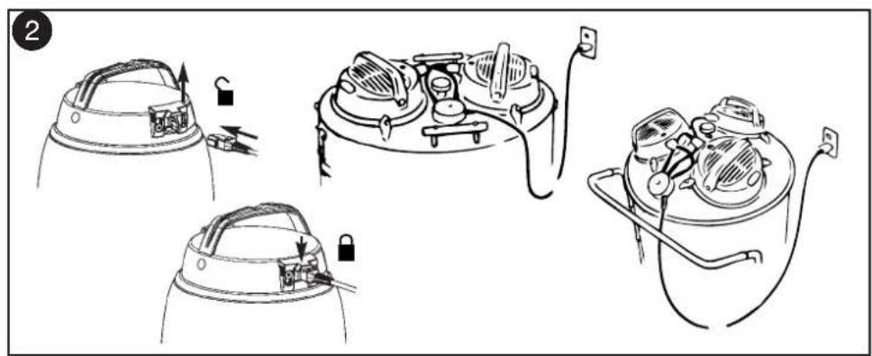
natural_image
Line drawings of two different hand-painted industrial equipment setups, one with a valve and the other with a coiled hose (no text or symbols)
natural_image
Line drawing of a hand operating a portable air conditioner with a rotating base (no text or symbols)90C
natural_image
Line drawing of a hand pressing down on a mechanical component with a coiled cable (no text or symbols)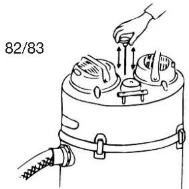
10
natural_image
Illustration of a hand placing objects into a tray with arrows indicating motion (no text or symbols)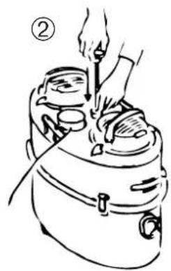
natural_image
Line drawing of a person using a handheld device to adjust or install equipment (no text or symbols present)③
natural_image
Simple line drawing of a hand holding a cylindrical object with a handle, no text or symbols present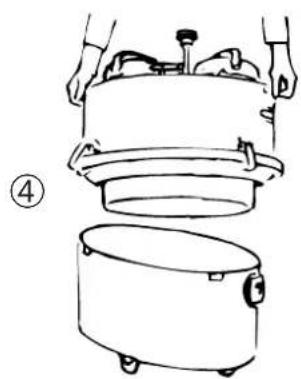
natural_image
Line drawing of a person installing or maintaining a large cylindrical device with a smaller cylindrical container (no text or symbols)⑤
natural_image
Simple line drawing of a person pouring liquid from a paper into a container (no text or symbols)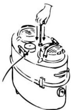
natural_image
Line drawing of a hand using a tool to lift or press down an open device (no text or symbols)⑥
11
natural_image
Illustration of a hand pressing down on a plate with a tray and a small object, no text or symbols present.①
natural_image
Line drawing of a hand operating a cart with a handle, no text or symbols present②

natural_image
Line drawing of a hand operating a cleaning machine with a lid and handle (no text or symbols)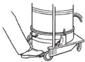
natural_image
Line drawing of a hand operating a cart with a hose, no text or symbols present③
12
①
②
③

13
①
②
③
natural_image
Diagram of an insect wing with labeled parts (g, a, b) and a magnified view of the wing (no text or symbols present)④
14
15
natural_image
Line drawing of a mechanical device with a handle and base plate (no text or symbols)16
natural_image
Line drawing of a mechanical device with a handle and base (no text or symbols)17
natural_image
Simple line drawing of a hairdryer with a cylindrical base and upward arrows indicating motion (no text or symbols)18
natural_image
Technical line drawing of a mechanical clamp or fixture with coiled spring and handle (no text or symbols)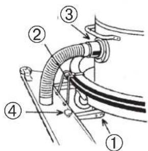
natural_image
Two parallel mechanical blades with textured surfaces, labeled with number 6 (no text or symbols on blades)6 - 9 Dansk
10 - 13 Norsk
14 - 17 Svenska
18 - 21 Suomi
22 - 25 English
26 - 29 Deutsch
30 - 33 Français
34 - 37 Nederlands
38 - 41 Español
42 - 45 Português
46 - 49 Italiano
50 - 53 Ελληνικά
55 - 57 EU declarations
58 - 59 Service
60 - 63 Data
DANSK
VIGTIGE ADVARSLER
Følg motsatt prosedyre for demontering.
Justering av gummilister
IMPORTANT SAFETY INSTRUCTIONS
When using an electrical appliance, basic precautions should always be followed, including the following:
READ ALL INSTRUCTIONS BEFORE USING THE APPLIANCE
WARNING
To reduce the risk of fire, electric shock, or injury:
* Do not leave appliance when plugged in. Unplug from outlet when not in use and before servicing.
* To reduce the risk of electric shock - do not use outdoor or on wet surfaces.
* Do not allow to be used as a toy. Close attention is necessary when used by or near children.
* Use only as described in this manual. Use only the manufacturer's recommended attachments.
* Do not use with damaged cord or plug. If appliance is not working as it should, has been dropped, damaged, left outdoors or dropped into water, return it to a service centre.
* Do not pull or carry by the cord, use cord as a handle, close a door on cord, or pull cord around sharp edges or corners. Do not run the appliance over cord. Keep cord away from heated surfaces.
* Do not unplug by pulling on cord. To unplug, grasp the plug, not the cord.
* Do not handle plug, cord or appliance with wet hands.
* Do not put any object into openings. Do not use with any opening blocked; keep free of dust, lint, hair, and anything that may reduce air flow.
* Keep hair, loose clothing, fingers, and all parts of body away from openings and moving parts.
* Turn off all controls before unplugging.
* Use extra care when cleaning on stairs.
* Do not use to pick up flammable or combustible liquids such as gasoline or use in areas where they may be present.
* Do not pick up anything that is burning or smoking, such as cigarettes, matches, or hot ashes, or any hazardous dusts.
* Do not use without dust bag and/or filters in place.
* Always turn off this appliance before connecting or disconnecting motorised nozzle.
* If this appliance is grounded, connect to a properly grounded outlet only. See grounding instruction.
* If this appliance is provided with double insulation. Use only identical replacement parts. See instruction for Servicing of Double-Insulated Appliances.
* Do not use outdoor or on wet surfaces. Do not expose to rain. Store indoors between max. 60 C (degrees centigrade) and min. 0 C (degrees centigrade).
SAVE THESE INSTRUCTIONS
This machine is only suitable for commercial use, for example in hotels, schools, hospitals, factories, shops and offices other than normal residential housekeeping purposes.
* This machine is not suitable for picking up health endangering dust.
* This machine is for dry use only and shall not be used or stored outdoors in wet conditions.
(Only for grounded appliances):
GROUNDING INSTRUCTIONS
This appliance must be grounded. If it should malfunction or breakdown, grounding provided a path of least resistance for electric current to reduce the risk of electric shock. This appliance is equipped with a cord having an equipment-grounding conductor and grounding plug. The plug must be
inserted into an appropriate outlet that is properly installed and grounded in accordance with all local codes and ordinances.
WARNING
Improper connection of the equipment-grounding conductor can result in a risk of electric shock. Check with a qualified electrician or service person if you are in doubt as to whether the outlet is properly grounded. Do not modify the plug provided with the appliance - if it will not fit the outlet, have a proper outlet installed by a qualified electrician.
(Only for cord-connected grounded appliances, having a rated current less than 15A and intended for use on a nominal 120-volt supply circuit):
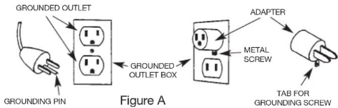
This appliance is for use on a nominal 120-volt circuit and has a grounding attachment plug that looks like the plug illustrated in figure A. Make sure that the appliance is connected to an outlet having the same configuration as the plug. No adapter should be used with this appliance.
(Only for all other grounded, cord-connected appliances):
flowchart
graph LR
    A["GROUNDING PIN"] --> B["Grounded Outlet Box"]
    B --> C["ADAPTER"]
    C --> D["TAB FOR GROUNDING SCREW"]
    B --> E["Grounded Outlet Box"]
    E --> F["METAL SCREW"]
This appliance is rated more than 15 amperes and is for use on a circuit having a nominal rating of 120 volts and is factory-equipped with a specific electric cord and plug to permit connection to a proper electric circuit. Make sure that the appliance is connected to an outlet having the same configuration as the plug. No adapter should be used with this appliance. If the appliance must be connected for use on a different type of electric circuit, the reconnection should be made by qualified service personnel.
(Only for double-insulated, cord-connected appliances): SERVICING OF DOUBLE-INSULATED APPLIANCES
A double insulated appliance is marked with one of the following: The words “DOUBLE INSULATION” or “DOUBLE INSULATED” or the double insulation symbol (square within a square).
In a double-insulated appliance, two systems of insulation are provided instead of grounding. No grounding means is provided on a double-insulated appliance, nor should a means for grounding be added to the appliance. Servicing a double-insulated appliance requires extreme care and knowledge of the system, and should be done by qualified service personnel. Replacement parts for a double-insulated appliance must be identical to the parts they replace.
IMPORTANT WARNINGS
- This machine is also suitable for commercial use, for example in hotels, schools, hospitals, factories, shops and offices for other than normal housekeeping purposes.
- This machine is not suitable for picking up health endangering dust, unless special authorised precautions are complied with.
- This machine is for dry use only and shall not be used or stored outdoors in wet conditions. Store indoors between max. 60 C (degrees centigrade) and min. 0 C (degrees centigrade).
-
The machine for vacuum dry dust must not be used for the suction of water or other liquids.
-
Live conductors must not be vacuum cleaned by the machine for dry dust before their current has been switch off. This is to avoid creating a short-cut through the dust remaining in the nozzles and tubes.
- The machine must not be used for picking up combustible or explosive materials, nor should it be used in an explosive atmosphere.
- Under no circumstances should the machine be used for picking up hot material. In particular the machine must not be used for cleaning open and closed fireplaces, ovens or similar that contain warm or glowing ashes.
- The machine must not be used if the electrical cord shows any sign of damage. Regularly inspect the cord for damage, in particular if it has been crushed, shut in a door or run over.
- The machine must not be used if it is faulty.
- Do not unplug by pulling on cord. To unplug, grasp the plug, not the cord.
- Always turn off this appliance before connecting or disconnecting motorised nozzle.
- When repairing or replacing the cord, the same type of cord as originally supplied with the machine must be used. This cord can be supplied by NILFISK.
- The plug must always be removed from the socket outlet before starting any service work of the machine or the cord.
- Repair of the electrical unit with motor or the cord must only be carried out by a skilled or instructed person after having disconnected the main switch installed prior to the machine or after having removed the plug from the current socket.
- No changes or modifications to the mechanical or electrical safety devices should be made.
Instructions for use
Before using the machine make sure that the frequency and voltage shown on the rating plate corresponds with the mains voltage.
Specifications and details are subject to change without prior notice.
On/off
Attaching the power cord 80P/90C
Place the appliance plug of the cord in the motor socket, only 80P. Pressing the button turns the motor on and off alternately.
① Detaching the power cord 80P/90C
Do not roll the cord tightly around the motor as this will place a strain on the cable and considerably shorten its life.
② Connection of power cords 82/83/625/626
The short cords from the junction box are connected to the motors. The long cord from the junction box is plugged into the wall socket.
The motors start and stop when the switches are operated.
Note
The motors must run simultaneously to ensure maximum suction power. The motors should always be switched on and off individually.
Power cord All Models
Avoid any damage which may be caused by running over, jamming, or pulling the power cord. When replacing the power cord make sure that an approved cord of the same type as the original is used.
Thermal cut-out protection (USA and Canada only - All Models)
The vacuum motor is provided with a thermal cut-out protection mechanism. This prevents the motor from overheating should a blockage occur.
Remove the cause of the blockage to allow free air passage. When the motor is cool, it will automatically start again.
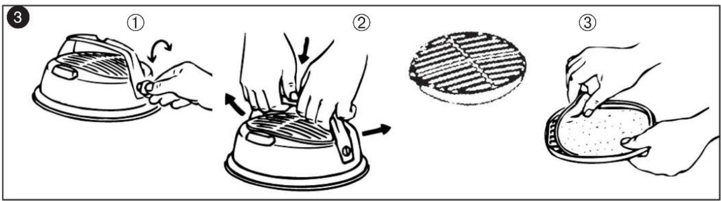
3 Diffuser All Model
The diffuser is easily replaceable.
Detaching the handle
① Turn the two screws with a coin until their slots are vertical.
② Release the handle by a gentle downward pressure at its center. Press until both ends spring out from the motor recess. Lift off the exhaust grill and the diffuser. The sound absorbent material must remain on top of the motor.
③ Remove the diffuser and mount the replacement. Replace the grill.
Replacing the handle
Place the handle into position and lock it by turning the screws until their slots are horizontal.
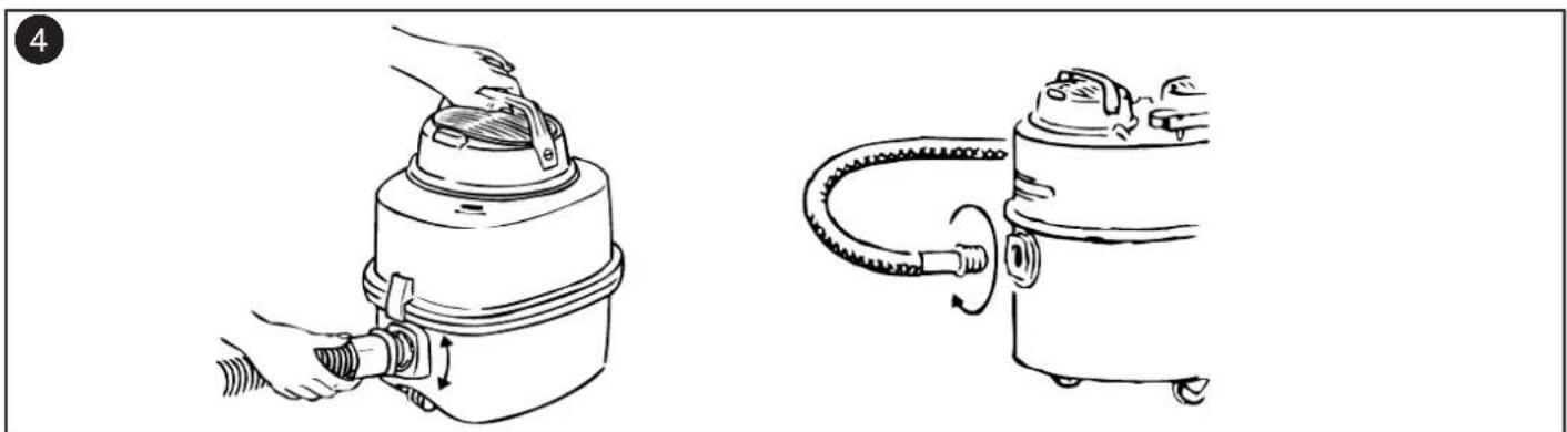
Hose and tubes All model
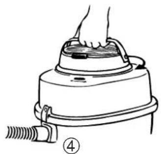
4 Hose connection
Insert the bayonet coupling in the suction inlet, and lock it in place by turning it clockwise.
Reverse this procedure to disconnect the hose.
5 Plastic hose and plastic tube
① Fitting hose to the curved tube. Slide the hose into the curved tube and adjust by turning until locking levers grip into position.
② Removing hose from curved tube. You may wish to remove the hose from the curved tube so that you can easily remove a blockage.
Push one of the locking levers with a screwdriver, as illustrated. Tip the locking lever until it is released. Repeat on the other locking lever. The curved tube can now be separated from the hose.
6 Suction power regulation on curved plastic tube
① The suction power of the nozzle can be regulated by the slide valve on the curved tube. Suction is most powerful when the valve is pushed forward to close the inlet.
② For cleaning of e.g. loose covers and curtains, the suction power can be reduced by sliding the valve backwards.
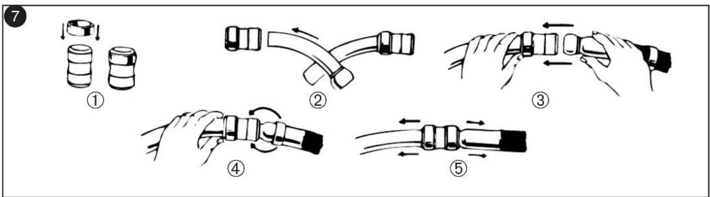
7 Rubber or plastic hose with curved steel tube
If the hose or curved tube is blocked, the curved tube can be detached from the hose to remove the obstruction.
Dismantling
Hold the ring closest to the curved tube and pass it over the wand by simultaneously pulling and turning.
Assembling
The rubber coupling makes work easier and prolongs the life of the hose. (If the coupling becomes tight, it should be removed and sprinkled liberally inside with French Chalk or talcum powder).
① Place rubber coupling on a flat surface and press one ring over the rim until it fits into the groove of the rubber muff.
② Push curved tube through the joint and pull it through as far
as it will go.
③ Grip curved tube with left hand close against the rubber muff and push ball socket of hose in as far as possible.
④ Turn or push the second ring into its correct position in the groove of the rubber coupling.
⑤ Pull in the directions indicated by the arrows and the hose is assembled.
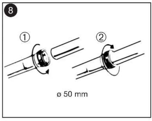
8 Assembling of the ∅50mm tubes 82/83/625/626
① Before the tubes and nozzle are assembled the locking ring is unscrewed counter-clockwise.
② Then the tube and nozzle are assembled and the locking ring is screwed clockwise until it grips.
Accessories
NILFISK supplies a large selection of tubes and nozzles for ordinary cleaning, overhead cleaning, and specific cleaning tasks.
See special leaflets for accessories.
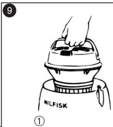
9 Shaking the filter Only 80P
The cleaner can also be used without the dust bag. In this case the dust is collected in the lower part of the container which is emptied as necessary. To keep suction power at a constant level the filter must be kept as clean as possible by shaking it at regular intervals. The filter should not be washed or brushed.
Removing the motor 80P
① Hold the motor handle and open the top catches. Lift off the motor.
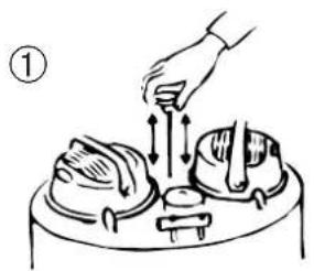
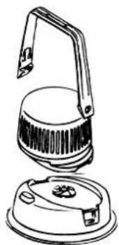
Removing the motor 90C
① Remove the motor by turning its handle counter-clockwise. Lift off the motor.
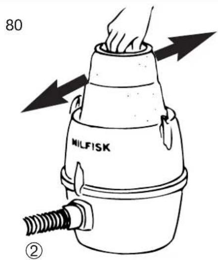
② The filter can be cleaned by vacuum it.
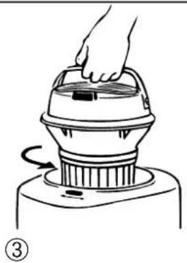
③ Replace the motor so that the on/off switch is in line with the on/off switch printed on the upper container. Turn the motor clockwise until a distinct click is heard. If the motor will not lock into position by turning, then press the red locking lever inside the container in the direction of the arrow.
② Pull out the filter by its blue bottom plate and shake it gently from side to side. The hose must remain fixed to the container during the shaking operation.
③ When mounting the motor make sure that the switch is directly over the suction inlet of the container and the plug is turned backwards.
Emptying the container
When the filter has been shaken and the hose detached, release the two latches and open the container. Lift off the top part and empty the lower part of the container.
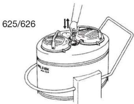
Shaking 82/83
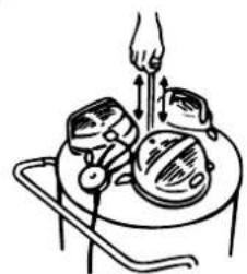
To keep the suction power constant the filter must be as clean as possible. The filter must therefore be shaken regularly. It can be shaken a number of times before the container needs emptying. Switch off the motor. Shake the filter several times by means of the shaking rod. The hose must be attached to the container during the shaking. The filter should not be washed or brushed.
Shaking
The filter shaker rod is depressed as far as possible until automatically releases itself, activating the filter shaking device.
Usually 3-4 movements in succession will be sufficient.
Do not wash or brush the filter, but keep it clean solely by frequent shaking or vacuuming with another cleaner. This machine is supplied with either cotton - or GORE-TEX filter.
Manometer
The vacuum cleaner can be fitted with a manometer, indicating the degree of clogging of the main filter. When the needle is in the red zone, the motor needs to be switched off and the filter shaken.
This is particularly useful in fixed pipework systems, where a drop in efficiency may not be immediately noticed.
10 Emptying the container 82
① Switch off the motors and shake the filter several times by means of the shaker rod. Leave the hose connected.
② Lock the shaker rod in highest position using the rubber stop. Remove the hose.
③ To release the dirt container, unfasten the four clips, and open to their full extent.
④ Remove the upper container with motors still in place.
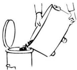
⑤ Empty the dust container.
⑥ Replace the upper container complete with motors, fasten clips against the container. Push the shaker rod down.
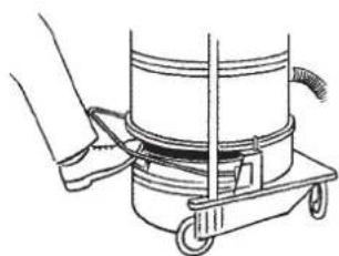
⑪ Emptying the waste container 83/625/626
① Switch off the motors, leave the hose connected and shake the filter as described in "Shaking the filter".
② By raising the pedal bar, the waste container is lowered to the ground and can either slid clear of the machine for disposal of waste, or the machine can be pushed forward to clear the container.
③ After emptying, the container is placed under the machine, with one handle to rear and the pedal bar pushed down, automatically lifting and sealing the container back in its position.
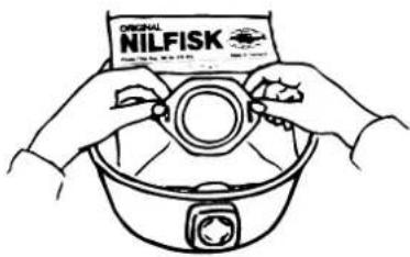
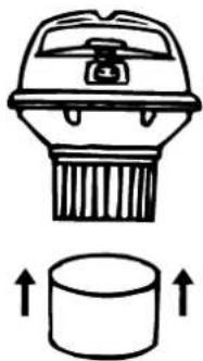
12 Suction with dust bag 80P/90C
The cleaner is supplied with two ply self-locating dust bags. To release the container, unfasten the two latches and lift off the upper part with the motor/filter section. Fix the dust bag as follows:
① Pierce the dust bag's perforation and plac n the lower container.
② Pull the blue dust bag plastic plate over the suction inlet with both hands.
③ Unfold the dust bag carefully. Replace the top container and lock the two latches.
Note
The suction efficiency depends on the size and quality of the dust bag. Use original Nilfisk bags only. If non-Nilfisk dust bags are used, and airlow restricted, overheating of the motor and subsequent damage may result.
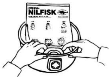
13 82/625/626
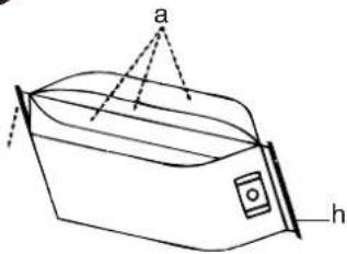
① In order to avoid having the paper bag tear while the machine is running, it is advisable to open the bag before installing it in the machine. This can be done by gently pulling open the pleats (a) that are on each side of the bag, so that the cross section of the bag is almost square.
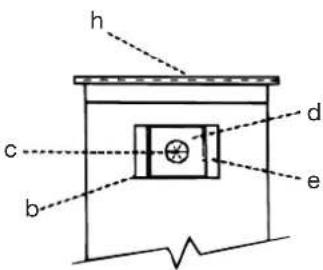
② To avoid tearing the bag at the paper bag inlet (b), gently push in and open the perforations (c) in the paper of the bag, just inside the hole of the rubber bag seal (d).
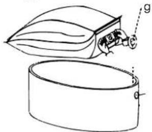
③ Install the opened bag in the lower container so that the paper bag inlet (b) is facing downward in the bottom of the container. Then carefully grasp the cardboard tabs (e) on each side of the bag seal with both hands and slide the bag seal over the inlet tube (g). Start from the bottom of the inlet tube and gently pull the seal over the inlet tube with a slight rocking or twisting motion, pulling as far up as the ribs on the inlet tube.
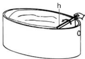
④ After the bag seal touches the ribs of the inlet tube, fold back the sewn (h) seam so it does not interfere with closing the container. Expand the sides of the bag in the container so that the top of the bag is even with the sides of the container.
Dust bag systems
For ease of handling and hygienic emptying, different kinds of emptying and dust bag systems are available.
Disposable container
For hazardous dust, a disposable container is available. When the container is full, it is sealed with a lid and a locking ring making the container safe to dispose.
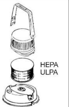
14 Exhaust filter All models
Exhaust filters are used when absolutely clean exhaust air is necessary. The exhaust filter is mounted on to the motor in place of the diffuser.
The exhaust filter is easily fitted and the filter element is replaceable.
A special handle and instructions for use are delivered together with the exhaust filter.
15 Blowing attachment
Mounting
Remove the diffuser and sound absorber (see page 2)
① Place the blowing adaptor 115620 on the motor. Each one is kept in place by handle of the motor.
② Fit the blowing attachment into the motor blowing adaptors.
③ Before connecting a hose make sure that it is clean - place its open end in the container inlet for a moment with the motors running and shake it.
16 Sound suppressor All models
The sound level of the vacuum cleaner is low. If an even lower sound level is required or desired, a sound suppressor can be fitted on to the motor.
The sound suppressor are mounted in place of the diffuser (see page 4).
The sound suppressor reduces the motor noise by another 4 dB corresponding to approximately 37%.
It is only possible at any one time to fit either exhaust filters or blowing attachment or sound suppressors.
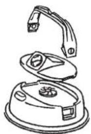
17 Motor protection filter
For special filtration tasks, the lower part of the motor can be fitted with a filter. This filter must be replaced on a regular basis.
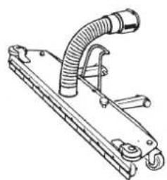
18 Fixed floor nozzle 82/83/625/626
The fixed floor nozzle is mounted to the container as follows:
The hinge lever is tipped forward.
① The fixed pin is placed in the slot in the suspension and the suspension and the brace is hooked on to it.
② The spring loaded pin is located into the hole on the opposite side of the container bracket.
③ Lift nozzle to allow hose to be connected to the container inlet, turning the bayonet fitting clockwise.
To disconnect, reverse above procedure.
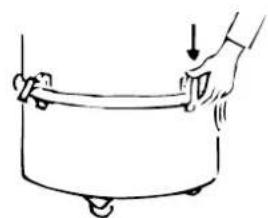
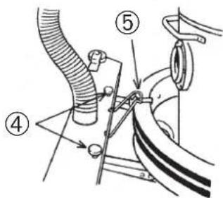
Adjustment of rubber blades
④ The distance of the rubber blades from the floor should be about 1 mm, and the adjustment is made by means of the two fingerscrews.
⑤ During idle periods or during transportation, the nozzle should be raised from the floor by placing the nozzle brace in the second notch on hinge level.
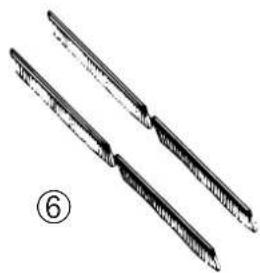
⑥ As an alternative a brush set consisting of floor brush strips is available.
Maintenance
Always keep the cleaner in a dry place. The bearings in the motor are pregreased and designed for continuous heavy work.
Depending on the number of running hours the dust filter should be replaced.
For details of service or maintenance please contact NILFISK directly.
Trouble-shooting
• the motor will not start
- a fuse may have blown and needs replacing.
- the cable or the wall socket may be defective and needs checking.
• the suction power is reduced
- the dust bag may be full and needs replacing, see page 4.
- the container may be full and needs emptying, see page 3-4.
- the filter may be clogged and needs shaking, see page 3-4.
- the hose, tube or nozzle may be blocked and needs to be cleared, see page 2-3.
- if the hose needs cleaning remove the locking ring, the curved wand and the rubber coupling, see page XXX.
• the vacuum cleaner stops (USA and Canada only)
- the thermal cut-out has switched off the motor as a result of an obstruction of the hose, wand or nozzle. Remove the cause of the obstruction.
- when the motor is cool, it will automatically start again.
- the motor will not stay locked in position on the container Only 90C
- The red locking lever in the container top is in the wrong position. Push the lever in the direction of the arrow.
DEUTSCH
⑪ Stofbak legen, 83/625/626
Ligar/desligar (On/off)
(Electro Magnetic Compatibility)
89/392/EØF M-direktivet (Machine)
Nilfisk-Advance A/S

Jørgen Jensen
Executive Vice-President
02
NILFISK
FIN
Executive Vice-President
05
FIN
NILFISK
s
Executive Vice-President
04
IRL
NILFISK
GB
EU Declaration of conformity for Nilfisk suction cleaners
Manufacturer Nilfisk-Advance A/S
Address Sognevej 25
DK-2605 Brøndby
Denmark
Telephone +45 43 23 81 00
Telefax +45 43 43 77 00
hereby declares that:
Suction cleaners
Nilfisk, Type
GM80P, GD90C, GM82, GS82, GM83, GS83, GM625, GM626
have been manufactured as from 1995 in conformity with the provision in the Council Directives:
73/23/EEC LV-Directive (Low Voltage Directive)
89/336/EEC EMC-Directive
(Electro Magnetic Compatibility)
89/392/EEC M-Directive (Machine)
Nilfisk-Advance A/S

Jørgen Jensen
Executive Vice-President
06
73/23/EEC LV-directive
89/336/EEC EMC-directive
89/392/EEC M-directive (regulamento
maquinaria)
Nilfisk-Advance A/S

Jørgen Jensen
Executive Vice-President
16
NILFISK
GR
(Electro Magnetic Compatibility)
89/392/EEC M-direktive (Machine)
Nilfisk-Advance A/S

Jørgen Jensen
Executive Vice-President
09
NILFISK
|
Executive Vice-President
11
SERVICE
Australia
Nilfisk-Advance Pty. Ltd.
ACN 003 762 623
Head office:
17 Leeds Street, Rhodes, N.S.W. 2138
(02) 9736 1244 - Fax (02) 9736 3910
Customer Response Centre:
1 800 011 013
Doornveld/Sphere Business Park
Industrie Asse 3, nr 11 - bus 41
1731 Zellik-Asse
📞 (02) 467.60.50 Fax (02) 463.44.16
Canada
Nilfisk-Advance Ltd.
396 Watline Avenue
Mississauga, Ontario L4Z 1X2
📞 (905) 712-3260 - Fax (905) 712-3255
Danmark
Nilfisk-Advance Nordic A/S
Berner Oy Automotive/Household
Sahaajankatu 14
00810 Helsinki
09-134 511 - Fax 09-134 51 540
Email: automotive@berner.fi
France
Nilfisk-Advance S.A.
BP 246
91944 Courtaboeuf Cedex
📞 (01) 69.59.87.00 - Télécopie (01) 69.59.87.01
Greece:
Embion S.A.
31-39 Wo Tong Tsui Street
Kwai Chung, N.T.
2427 59 51 - Fax 2487 58 28
Ireland
Nilfisk-Advance Ltd.
28 Sandyford Office Park
Dublin 18
+353 1 2943838 - Fax +353 1 2943845
Italia
Nilfisk-Advance S.p.A.
Localita Novella Terza
6 Mls, Old Klang Road
46000 Petaling Jaya
6003-7932919 - Fax 6003-7932912
Nederland
Nilfisk-Advance B.V.
Flevolaan 7, Postbus 341
1380 AH Weesp
0294-462121 - Fax 0294-430053
New Zealand
Nilfisk-Advance Limited
477 Great South Road, Penrose
Auckland
📞 (09) 525 0092 - Fax (09) 525 6440
Norge
Nilfisk-Advance AS
Ulvenvejen 89C, 0680 Oslo, Postboks 196, Manglerud, 0612 Oslo
22 08 63 50 - Fax 22 08 63 63
Distriktsrepresentanter over hele landet
Portugal
Nilfisk-Advance Lda.
22 Woodlands Ind Park E1
Singapore 757740
📞 (65) 759 9100 - Fax (65) 759 9133
Sverige
Nilfisk-Advance AB
Sjöbjörnsvägen 5
Box 44045, 117 67 Stockholm
0855 94400 - Fax 0855 94430
SERVICE
Taiwan
Nilfisk-Advance Ltd.
1 F, No. 23, Lane 132, Sec. 2
Ta An Road, Taipei
700 22 68 - Fax 784 08 43
United Kingdom
Nilfisk-Advance Limited
Newmarket Road
Bury St. Edmunds
Suffolk IP33 3SR
(01284) 763163 Fax (01284) 750562
USA
Nilfisk-Advance Inc.
14600 21st Avenua North
Plymooth, MN 55447-3408
+1612 476 2235 - Fax 1612 473 1764
Nilfisk-Advance America, Inc.
300 Technology Drive
Malvern, PA 19355
(610) 647-6420 - Fax (610) 647-6427
Österreich
Specifications and details are subject to change without prior notice.
| DEUTSCH SPEZIFIKATIONEN | GM 80P220-240V | GM 80P110-120V | GM 80P100V | GD 90C220-240V | GD 90C110-120V | GD 90C100V | GM 82220-240V | GS 82220-240V | GM 82110-120V | GS 82110-120V | GS 82100V | GM 83220-240V | GS 83220-240V | GS 83110-120V | GS 83200V | GM 625220-240VGM motor | GM 625110-120VGM motor | GM 625110-120VGM motor | GM 625100VGM motor | GM 626220-240VGM motor | GM 626110-120VGM motor | GM 626110-120VGM motor | GM 626100VGM motor | |
| Leistungsaufnahme Motor | W | 1200 1100 850 | 1200 1100 850 | 2400 1600 | 2200 1600 | 1200 3600 | 2450 2450 | 1800 2400 | 2200 1600 | 1170 | 2400 2200 | 1600 | 1170 | |||||||||||
| Leistungsaufnahme Motor, max. | W | 1300 1200 950 | 1300 1200 950 | 2600 1700 | 2400 1700 | 1300 4100 | 2600 2600 | 2000 2600 | 2400 1700 | 1280 | 2600 2400 | 1700 | 1290 | |||||||||||
| Schutzklasse (Feucht., Staub) | - | IP40 IP40 | IP40 IP40 | IP40 IP40 | IP40 IP40 | IP40 IP40 | IP40 IP40 | IP40 IP40 | IP40 IP40 | IP40 IP40 | IP40 IP40 | IP40 IP40 | ||||||||||||
| Schutzklasse (elektrisch)oder geordet | - | II □ | II □ | II □ | II □ | II □ | II □ | II □ | II □ | II □ | II □ | II □ | II □ | II □ | II □ | II □ | II □ | II □ | II □ | II □ | ||||
| Luftmenge mit Schlauch | I/Sek. | 38 | 38 | 33 | 38 | 38 | 33 | 80 | 67 | 80 | 67 | 61 | - | 82 | 82 | 70 | 80 | 80 | 67 | 61 | 80 | 80 | 67 | 61 |
| Luftmenge ohne Schlauch | I/Sek. | - | - | - | - | - | - | 90 | 75 | 88 | 75 | 65 | 135 | 93 | 93 | 78 | 90 | 88 | 75 | 65 | 90 | 88 | 75 | 65 |
| Unterdruck | kPa | 20 | 20 | 18 | 20 | 20 | 18 | 20 | 15 | 20 | 15 | 14 | 22 | 15 | 15 | 14 | 20 | 20 | 15 | 14 | 20 | 20 | 15 | 14 |
| Saugleistung mit Schlauch | W | 270 | 250 | 200 | 270 | 250 | 200 | 510 | 360 | 500 | 360 | 265 | 750 | 485 | 485 | 380 | 510 | 500 | 360 | 265 | 510 | 500 | 360 | 265 |
| Saugleistung ohne Schlauch | W | - | - | - | - | - | - | 540 | 430 | 530 | 410 | 300 | 800 | 590 | 580 | 470 | 540 | 530 | 410 | 300 | 540 | 530 | 410 | 300 |
| Schaldruckpegel in 1,5m Abstand (ISO 112D3)a) Staubsauger mit Schlauch dB(A)/20μPa | 63 | 63 | 63 | 63 | 63 | 63 | - | - | - | - | - | - | - | - | - | - | - | - | - | - | - | - | - | |
| b) Staubsauger ohne Schlauch dB(A)/20μPa | 61 | 61 | 61 | 61 | 61 | 61 | 67 | 64 | 64,5 | 64 | 64 | 67 | 63,5 | 63,5 | - | 67 | 64 | 64 | 64 | 67 | 64 | 64 | 64 | |
| Hauptfilterfläche, Baumwolle | cm2 | 2100 | 2100 | 2100 | 800 | 800 | 800 | 6600 | 6600 | 6600 | 6600 | 6600 | 18500 | 14300 | 14300 | 14300 | 6600 | 6600 | 6600 | 6600 | 16000 | 16000 | 16000 | 16000 |
| Ablutfliter, HEPA, Fläche | cm2 | 3300 | 3300 | 3300 | 3300 | 3300 | 3300 | 2x3300 | 2x3300 | 2x3300 | 2x3300 | 2x3300 | 3x3300 | 3x3300 | 3x3300 | 3x3300 | 2x3300 | 2x3300 | 2x3300 | 2x3300 | 2x3300 | 2x3300 | 2x3300 | 2x3300 |
| Ablutfliter, ULPA, Fläche | cm2 | 4600 | 4600 | 4600 | 4600 | 4600 | 4600 | 2x4600 | 2x4600 | 2x4600 | 2x4600 | 2x4600 | 3x4600 | 3x4600 | 3x4600 | 3x4600 | 2x4600 | 2x4600 | 2x4600 | 2x4600 | 2x4600 | 2x4600 | 2x4600 | 2x4600 |
| Behälter-Kapazität | Liter | 12,25 | 12,25 | 12,25 | 14,5 | 14,5 | 14,5 | 46 | 46 | 46 | 46 | 46 | 69 | 69 | 69 | 69 | 46 | 46 | 46 | 46 | 46 | 46 | 46 | 46 |
| Staubbeutel-Kapazität | Liter | 6,25 | 6,25 | 6,25 | 6,50 | 6,50 | 6,50 | 46 | 46 | 46 | 46 | 46 | - | - | - | - | 46 | 46 | 46 | 46 | 46 | 46 | 46 | 46 |
| Masse (Gewicht) | kg | 5 | 5 | 5 | 5 | 5 | 5 | 28 | 28 | 28 | 28 | 28 | 53 | 53 | 53 | 53 | 50 | 50 | 50 | 50 | 55 | 55 | 55 | 55 |