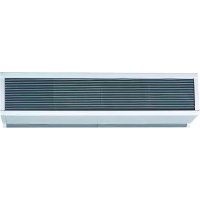
DAB15E - Air Conditioning DIMPLEX - Free user manual and instructions
Find the device manual for free DAB15E DIMPLEX in PDF.


| Product Type | Electric Heated Air Curtain |
| Brand | Dimplex |
| Model | DAB15E |
| Category | Air Conditioning |
| Heating Power | 9.0 / 18.0 kW (two levels) |
| Power Supply | 380-415 V ~ 3PN |
| Rated Current | 27 A |
| Weight | 35 kg |
| Maximum Installation Height | 2.7 m |
| Minimum Distance to Ceiling | 100 mm |
| Minimum Height Above Floor (Horizontal Mounting) | 1.8 m |
| Mounting Positions | Wall (horizontal), ceiling, vertical (CAB only) |
| Fan Speeds | Slow and Fast |
| Functions | Ventilation only, low heat, high heat, auto/manual mode, compatible with door contact |
| Thermal Protection | Thermal cutouts with manual reset |
| Cooling Function | No (heating only) |
| Cleaning | Removable grilles for internal suction; frequency: at least every 3 months |
| Recommended Inspection | Weekly (dust accumulation) |
| Electrical Connection | By a qualified electrician; mandatory local disconnector (3 mm gap per pole) |
| Spare Parts and Repairability | Contact after-sales service or retailer; motors do not require lubrication |
| Warranty | According to the conditions in force in the country of purchase |
Frequently Asked Questions - DAB15E DIMPLEX
User questions about DAB15E DIMPLEX
0 question about this device. Answer the ones you know or ask your own.
Ask a new question about this device
Download the instructions for your Air Conditioning in PDF format for free! Find your manual DAB15E - DIMPLEX and take your electronic device back in hand. On this page are published all the documents necessary for the use of your device. DAB15E by DIMPLEX.
USER MANUAL DAB15E DIMPLEX
CAB10A, CAB10E, CAB10W, CAB15A, CAB15E & CAB15WDAB10A, DAB10E, DAB10W, DAB15A, DAB15E & DAB15W
UKD
FR
NL
IT
PL
08/18957/0 - Issue 10
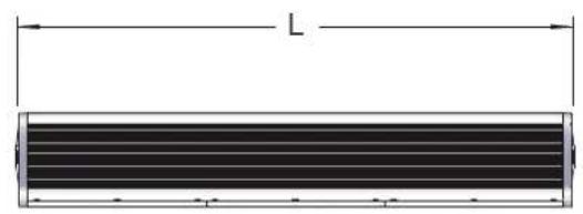
①
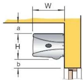
LWH
CAB 10 E/W/A 1065 320 262
CAB 15 E/W/A 1569 320 262
DAB 10 E/W/A 1057 391 361
DAB 15 E/W/A 1557 391 361
10
UK 1
DE 11
FR 16
NL 21
IT 26
PL 32
IMPORTANT: THESE INSTRUCTIONS SHOULD BE READ CAREFULLY AND RETAINED FOR FUTURE REFERENCE
IMPORTANT SAFETY ADVICE
DO NOT COVER OR OBSTRUCT the air inlet or outlet grille.
WARNING: A means for disconnection must be incorporated in the fixed wiring of the premises in accordance with the wiring rules.
WARNING: Always isolate the mains electrical supply before performing any work on these products.
WARNING: Where multiple units are installed ensure that the supply to each of the air curtains is isolated before any maintenance work begins. Any and all invasive work (inside of the air curtain's outer casing) on these products must be carried out by a suitably qualified, competent and approved electrician.
WARNING: Failure to adequately maintain the unit and provide a suitable cleaning schedule will result in a loss of performance, a reduction in the life expectancy of the air curtain and an increased risk of overheating and fire with electrically heated models.
Do not use this heater in areas where excessive dust exists.
This heater must not be located immediately above or below a fixed socket outlet or connection box.
A suitable termination to the fixed wiring of the premises must be provided adjacent to the final position of the appliance.
This product should be mounted safely to solid wall or ceiling surfaces only.
This product must not be subjected to water spray or immersion.
Ensure the supply cables are of adequate current carrying capacity and are protected by a suitable fuse. Cable size selection, to be selected in accordance with the maximum loading / demand of the product, and protected by a suitably rated overcurrent protection device.
If the appliance is mounted in a toilet or washroom, the appliance should be mounted such that no part of it can be touched by a person using a fixed bath or shower.
If the appliance is mounted in a toilet or washroom an isolating switch must be provided outside the washroom adjacent to the entrance door.
This appliance is not intended for use by persons (including children) with reduced physical, sensory or mental capabilities, or lack of experience and knowledge, unless they have been given supervision or instruction concerning use of appliance by a person responsible for their safety.
This appliance can be used by children from 8 years and above and persons with reduced physical, sensory or mental capabilities or lack of experience and knowledge if they have been given supervision or instruction concerning use of the appliance. Children shall not play with the appliance. Cleaning and user maintenance shall not be made by children without supervision.
Children of less than 3 years should be kept away unless continuously supervised. Children aged from 3 years and less than 8 years shall only switch on/off the appliance provided that it has been placed or installed in its intended normal operating position and they have been given supervision or instruction concerning use of the appliance in a safe way and understand the hazards involved. Children aged from 3 years and less than 8 years shall not plug in, regulate and clean the appliance or perform user maintenance.
CAUTION - Some parts of this product can become very hot and cause burns. Particular attention has to be given where children and vulnerable people are present.
WARNING - This heater is not equipped with a device to control the room temperature.
Do not use this heater in small rooms when they are occupied by persons not capable of leaving the room, unless constant supervision is provided.
INSPECTION
The frequency of the cleaning schedule is dependent upon the environment the air curtain has been installed into. As a minimum Dimplex recommend a weekly inspection to ensure that there is no significant build-up of dust or dirt reducing the performance of the air curtain and causing nuisance smell. Upon inspection, if any foreign objects are encountered which may cause damage to the fan, impellors or elements they must be removed.
The external appearance of the air curtain can be maintained by wiping occasionally with a damp cloth. For stain removal, a weak soap solution can be applied with a cloth and the surface wiped dry. Care must be taken to avoid any moisture ingress into the product.
- The inside of the air curtain must be cleaned at a minimum interval of once every 3 months, or more frequently if the weekly inspection deems it necessary. To clean the product remove the inlet grills by doing the following:
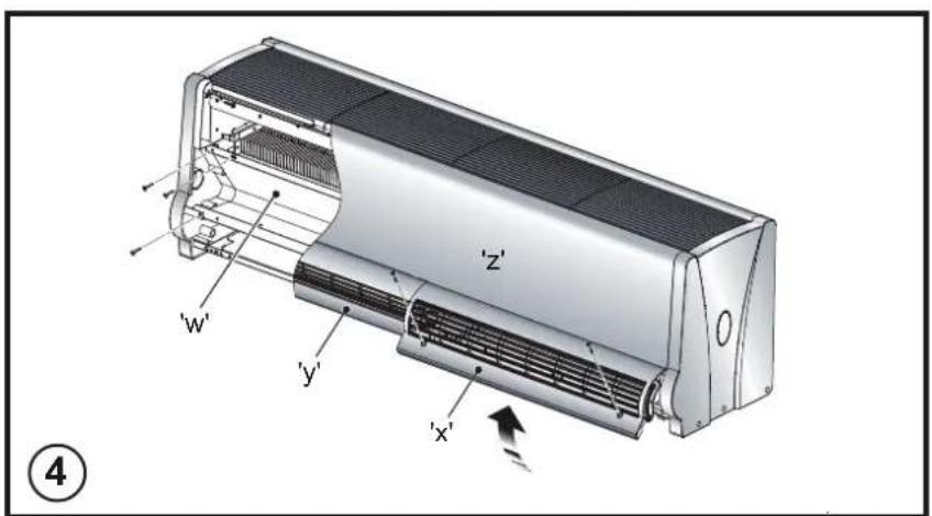
a. Using a flat head screwdriver, loosen both outlet grill screws to remove the grill ('x' in Fig. 4)
b. Using a Philips head screwdriver, remove the three M4 screws to remove the bottom panel ('z' in Fig. 4)
c. Locate and remove the two M4 screws located behind the inlet grills on the lower left and right hand sides (fi xed to the end caps)
d. Rotate and remove the inlet grill to expose the heating elements
- Once the heater bank has been accessed the unit can be cleaned using a vacuum cleaner with a brush attachment being careful not to disturb or damage the internal wiring or thermal cutouts. When the element bank has been cleaned, the inlet grill must be replaced before the air curtain is turned back on.
- Please note that the motors do not require any additional lubrication.
Electrical
The installation of this appliance should be carried out by a competent electrician and be in accordance with the current IEE wiring regulations.
Fixing Positions
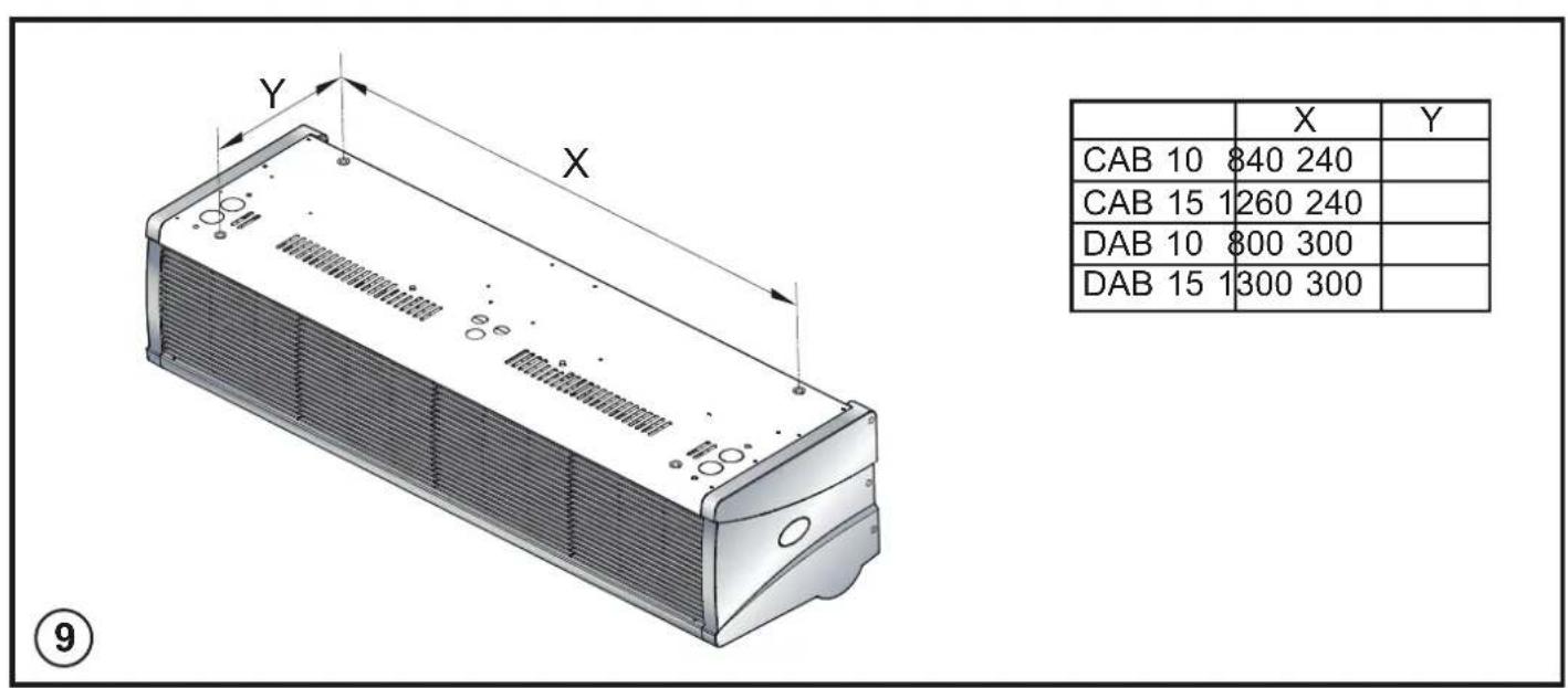
This appliance may be either wall-mounted, vertically mounted (CAB only) or fixed to a ceiling - see Fig. 3 for various fixing positions and 'Mounting' sections below, for fixing details.
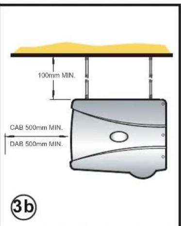
A minimum distance of 100mm is required from top of the appliance to ceiling (see 'a' in Fig. 1) and also the distance between the bottom of the appliance and the top of the door should be kept to a minimum (see 'b' in Fig. 1).
There should be at least a distance of 500mm from the front of the heater and any obstructing surfaces.
When horizontally mounted, this appliance should not be mounted less than 1.8m from the floor.
This appliance should not be fully encased.
The unit must be installed in an area where airflow into and out of the heater is unobstructed.
Models
| Model Heat Output kW | Electrical Supply E | Electrical Load A | Weight KG | Max Installed height M |
| AMBIENT / COLD STORE | ||||
| CAB10An/ a220-240V~1PN0.315.52.7 | ||||
| CAB15A | n/a | 220-240V | ~1PN | 0.5 |
| DAB10A | n/a | 220-240V | ~1PN | 1.5 |
| DAB15A | n/a | 220-240V | ~1PN | 2.3 |
| ELECTRICALLY HEATED | ||||
| CAB10E | 4.5 / 9.0 380-415V ~3PN 14 | 20.5 2.7 | ||
| CAB15E | 6.75 / 13.5 | 380-415V ~3PN | 20 | 29 |
| DAB10E | 6.0 / 12.0 | 380-415V ~3PN | 18 | 26.5 |
| DAB15E | 9.0 / 18.0 | 380-415V ~3PN | 27 | 35 |
| WATER HEATED (at 82/71 °C - LPHW)** | ||||
| CAB10W | 9.0220-240V~1PN0.317.72.7 | |||
| CAB15W | 13.5 | 220-240V ~1PN | 0.5 | 24.6 |
| DAB10W | 12.0 | 220-240V ~1PN | 1.5 | 24.7 |
| DAB15W | 18.0 | 220-240V ~1PN | 2.3 | 31.9 |
Wall Mounting
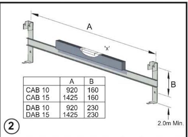
Using the wall mounting bracket as a guide (see Fig. 2) mark off hole positions on the wall (a minimum height of 2.0 metres is required from the floor level to the bottom of the bracket).
Position the bracket such that the air outlet of the installed air barriers will be as close to the top of the doorway as possible but will remain unobstructed when installation is complete.
Solid brick or concrete block walls must be drilled and plugged (using a spirit level as a guide - see 'x' in Fig. 2 - to ensure the bracket is level) with rawplug No. 8 size fibre inserts. The plug must be located in the solid part of the wall and not just in the plaster layer.
When fi xing to 'panel' walls, the wall bracket should be attached to the stud-work using No. 8 wood screws or by an alternative, equally secure method of fi xing.
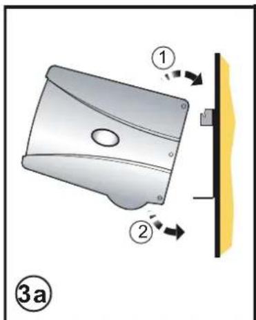
Once the wall bracket has been fitted, the air barrier can be clipped in place as shown in Fig. 3a.
Ceiling Mounting
By using threaded inserts in the top panel of the air barrier, attachment to a ceiling over the product can be achieved using suitable M8 threaded steel rod or similar supports of sufficient strength - see Fig. 3b.
Vertical Mounting
When mounting the CAB units vertically use the mounting kit CABVM1.
Multiple Units
When connecting multiple units together use the kit CABM1.
Electrical connection
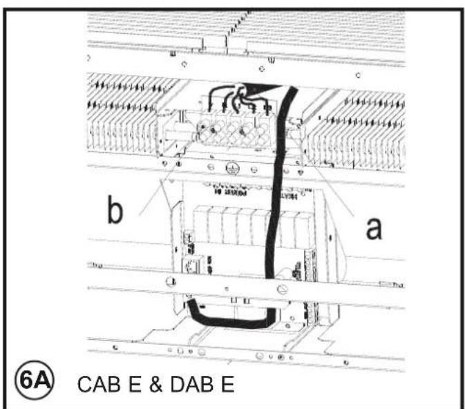
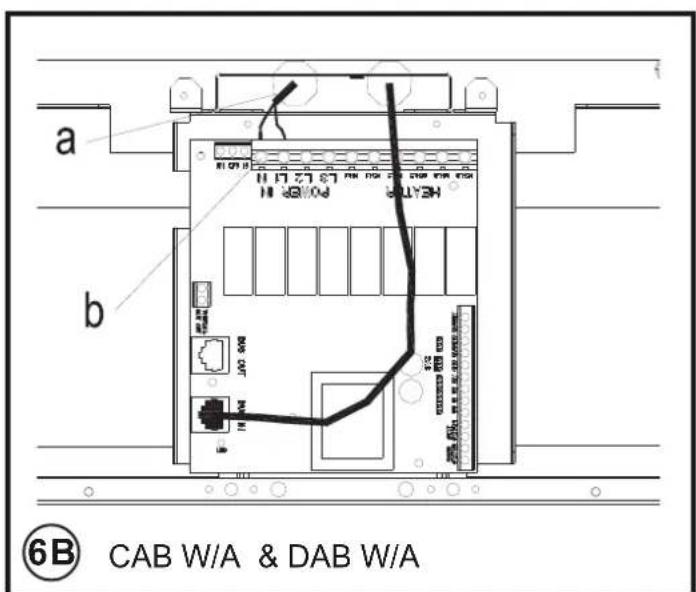
All products are fitted with a microprocessor control. Electrical power and control connections are made as shown in Fig. 6. A suitable local isolating switch must be provided in the electrical supply circuit with at least 3mm clearance on each pole.
Means for disconnection must be incorporated in the fixed wiring in accordance with the wiring rules.
In order to access the electrical connections, remove the outlet grilles ('x', and 'y' in Fig. 4) by releasing the quick release fasteners and hinging the mouldings as shown. Remove the bottom panel ('z' in Fig. 4) and also remove the pressure plate ('w' in Fig. 4).
All Electric Models - Having removed a 'knock out' in the top panel, feed an appropriate supply cable (see 'a' in Fig. 6A) through a suitable cable gland (not supplied) fitted in the top panel and attach to the terminal block (see 'b' in Fig. 6A).
All Water heated and Ambient Models - Having removed a7knock out' in the top panel, feed an appropriate supply cable (see 'a' in Fig. 6B) through a suitable cable gland (not supplied) fitted in the top panel and attach to the PCB (see 'b' in Fig. 6B).
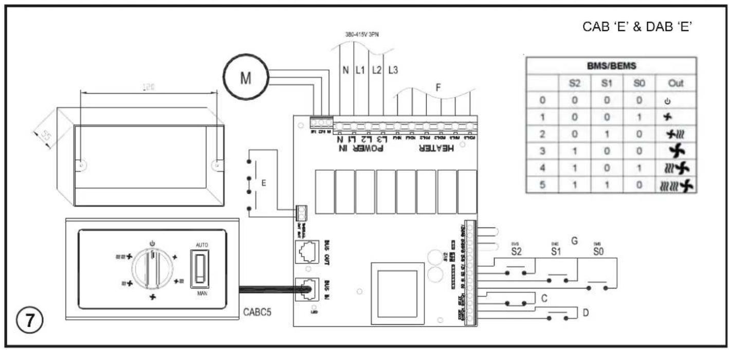
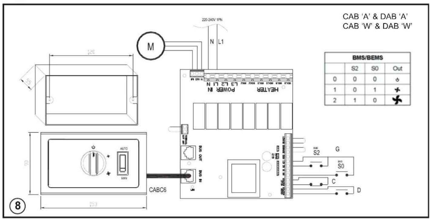
All Models - A suitable cable (CAT5 or equivalent) for a switch panel (kit ref. - CABC5 for electrically heated models or CABC6 for water heated/ambient models) can be similarly introduced through the top panel and plugged into the circuit board as shown in Fig. 6A & 6B. If the unit is to be operated in conjunction with a door switch, a normally open or closed switch, as required for the application should be wired as per Fig. 7 & 8.
Note: If using a door switch, an additional 2 core (low Voltage) cable is required between the door switch and the air barriers.
If the unit is to be connected to a Building Energy Management System, connections are made as per Fig. 7 & 8 as appropriate. Ensure that the air curtain is securely fastened in position and that the supply cables are firmly clamped before operating the appliance.
Water connection
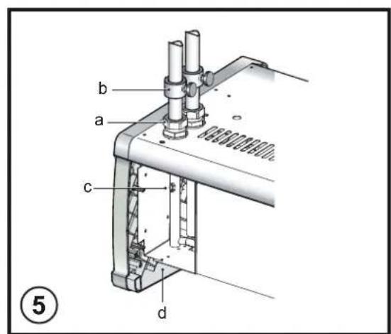
Models designed for use in conjunction with a low pressure hot water supply should be individually connected (in a parallel circuit) to the flow and return pipe-work. Connections (see 'a' in Fig. 5) are: 12 "BSPT (CAB series) and 34 " BSPT (DAB series) and isolation valves (see 'b' in Fig. 5) should be fitted as close to the air barrier connection points as possible. For commissioning, air bleed valves (see 'c' in Fig. 5) are fitted to the coil, which can be accessed by removal of the lower panel and intake grille - see Fig. 4. The drain (see 'd' in Fig. 5) can also be accessed when the grille and lower panel is removed.
Maximum water supply conditions are 125^ and 8 bar.
To aid installation, the water coil connections may be moved to either side of the appliance. By removing the water coil and appropriate knockouts the water coil can then be re-inserted into the required orientation. This procedure should be carried out before mounting the appliance.
Switch Panel Installation
The backing box (standard double gang) should be mounted onto a suitable wall. Suitable conduit should be used where applicable to carry the cable between the heater and the switch. A CAT5 LAN cable with straight through connections should be used to connect the switch panel to the appliance PCB.
Warning: Ensure cable is secure and the cable path does not come into contact with heater element or other moving parts. Test all switch settings once installation is complete.
Electrically heated variants
Operation using switch box - CABC5
Switch on electrical supply to the air curtain. Rotate the switch to the desired heat setting. Settings available are;

Standby

Low
Fan
Low Fat with Low Heat

High
Fan
High with Low Heat

With Full Heat
The rocker (auto / manual) switch allows for manual override of a door switch if fi tted. Manual allows the appliance to run at the desire setting, while Auto provides an energy saving feature by shutting down the appliance while the door is closed.
The unit should always be switched to Standby using the switch box control, and not switched off by mains power supply interruption.
When the unit is switched to Standby (via the switch box) the fan will run on for 1 minute without heat to discharge any residual energy from the heating elements. When fi rst turned on the control will run through a system check. The selected settings will be reached and maintained after a 30 second period.
Thermostatic control (optional)
By including a single pole bi-metallic or electronic thermostat to the connections as per 'C' in Fig. 7 the following functionality is introduced dependant on heat switch setting.
-Fan only-No effect
- Half Heat Heater will reduce to Fan only
- Full Heat-Heater will reduce to Half Heat
Thermal Safety cut outs
The power supply to the heating elements will be interrupted if one or a combination of the following abnormal events occur:
- Air inlet or outlet grilles are obstructed.
- Internal ventilation is impaired due to build up of dust and fluff.
- Blower unit stalls.
To reset the thermal safety cut-outs, access reset buttons by following the steps below;
a. IMPORTANT - Isolate electric supply.
b. Remove the inlet grilles using a fl at head screwdriver, loosen both outlet grill screws to remove the grill ('x' in Fig. 4)
c. Using a Philips head screwdriver, remove the three M4 screws to remove the bottom panel ('z' in Fig. 4)
d. Locate and remove the two M4 screws located behind the inlet grills on the lower left and right hand sides (fi xed to the end caps)
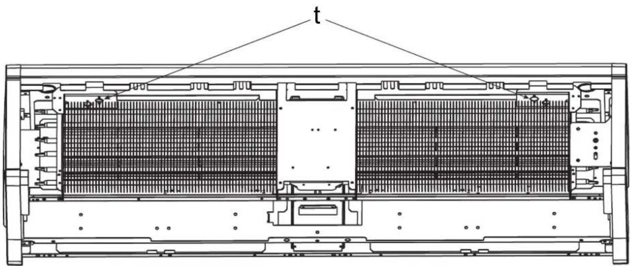
e. Rotate and remove the inlet grill to expose the safety cut-outs (t' Fig. 10)
Before re-setting the reason for activation must be determined and corrective action taken.
Door switch control (Electric models)
By including a door switch in the circuit as per 'D' in Fig. 7, the air barrier will respond to door openings as follows:
(1) Door opening will energise the air barrier at the set conditions (switch box settings).
(2) On door closure operation will continue at the set conditions for a further 1 minute.
(3) Between 1 minute and 2 minutes from door closure, set back operation, 12 heat (if heat selected) and 12 fan will activate.
(4) Between 2 minutes and 3 minutes, the fan only (1/2 speed) shut down cycle will be engaged.
(5) After 3 minutes, the air curtain will return to a dormant state until the door is re opened.
If the door re-opens during this 3 minute run on cycle, the process will restart at (1).
Low pressure hot water heated / Ambient (fan only) variants
Operation using switch box - CABC6
Switch on electrical supply to the air curtain. Rotate the switch to the desired heat setting. Settings available are;
OFF - Low Fan - High Fan
The rocker (auto / manual) switch allows for manual override of a door switch if fitted. Manual allows the appliance to run at the desire setting, while Auto provides an energy saving feature by shutting down the appliance while the door is closed. The unit should always be switched OFF using the switch box control, and not by mains power supply interruption.
When first turned on the control will run through a system check. The selected settings will be reached and maintained after a 30 second period.
Thermostatic control (optional)
1) A thermostatic regulation valve with a remote sensing bulb (not supplied) can be positioned in the supply water pipe-work to regulate the heat output.
2) An electrical 3-Port Solenoid Valve can also be connected into the system. Please contact your service agent using the contact details for more details.
Door switch control (Water / Ambient models)
By including a door switch in the circuit as shown in Fig. 8 as appropriate, the air barrier will respond to door openings as follows:
(1) Door opening will energise the air barrier at the set conditions (switch box settings).
(2) On door closure operation will continue at the set conditions for a further 1 minute.
(3) Between 1 minute and 2 minutes from door closure 12 fan set back operation will activate.
(4) After 2 minutes, the air barrier will return to a dormant state until the door is re-opened. If the door re-opens during this 2 minute run on cycle, the process will re start at (1).
Wiring Diagrams
CAB & DAB 'E' - Electric models - see Fig. 7
CAB & DAB 'W' & 'A' - Water & Ambient models - see Fig. 8
C-Thermostat
D - Door Switch (Optional)
E - Thermal Safety Cut-out Circuit
F - Elements
G - BMS Switches (Optional) (S0, S1, S2)
M-Motor
Remote (BMS/BEMS) Operation
Connection to Building Energy Management Control Systems (BEMS) is possible so that remote control of the air-barrier can be carried out in conjunction with other equipment. Please refer to the table in Fig. 7 & 8 to make the appropriate connections to the PCB. While the Appliance is connected to BMS/BEMS the supplied controller must be disconnected.
Modular Connection
Refer to instructions provided with the modular linking kit.
Recessed Installation
Refer to instructions provided with the recess installation kit.
Recycling
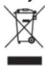
For electrical products sold within the European Community. At the end of the electrical products useful life it should not be disposed of with household waste. Please recycle where facilities exist. Check with your Local Authority or retailer
for recycling advice in your country.
Cleaning
WARNING: DISCONNECT SUPPLY before
carrying out maintenance.
External appearance can be maintained by wiping occasionally with a damp cloth; for stain removal, a weak soap solution can be applied with a cloth and the surface wiped dry. Care must be taken to avoid any moisture ingress into the product.
After Sales Service
Should you require after sales service or should you need to purchase any spares, please contact the retailer from whom the appliance was purchased or contact the service number relevant to your country on the warranty card. Please do not return a faulty product to us in the first instance as this may result in loss or damage and delay in providing you with a satisfactory service.
Please retain your receipt as proof of purchase.
-
Fan only - No effect
-
Half Heat - water will reduce to Fan only
-Full Heat- -Water will reduce to Half Heat
Telecomando (BMS/BEMS)
UK - Warranty The warranty conditions in the country of purchase apply to this appliance. Information can be obtained at any time from the retailer from whom the appliance was purchased. For claims under guarantee the sales receipt must be produced and the claims must be forwarded within the guarantee period. The right to claim under guarantee expires in case that the device has been damaged, used in an inappropriate way or that unauthorized manipulations have been carried out.
- Warranty Card
- Guarantee Period (in Years) 3. Model(s)
- Date of Purchase
- Stamp & Signature of retailer 6. Fault/Defect
- Contact Number & Address
DE
- IMPORTANT: THESE INSTRUCTIONS SHOULD BE READ CAREFULLY AND RETAINED FOR FUTURE REFERENCE
- IMPORTANT SAFETY ADVICE
- DO NOT COVER OR OBSTRUCT the air inlet or outlet grille.
- CAUTION - Some parts of this product can become very hot and cause burns. Particular attention has to be given where children and vulnerable people are present.
- INSPECTION
- Electrical
- Fixing Positions
- Wall Mounting
- Ceiling Mounting
- Vertical Mounting
- Multiple Units
- Electrical connection
- Water connection
- Maximum water supply conditions are 125°C and 8 bar.
- Switch Panel Installation
- Electrically heated variants
- Operation using switch box - CABC5
- Standby
- Low Fat with Low Heat
- High with Low Heat
- With Full Heat
- The unit should always be switched to Standby using the switch box control, and not switched off by mains power supply interruption.
- Thermostatic control (optional)
- Thermal Safety cut outs
- Door switch control (Electric models)
- Low pressure hot water heated / Ambient (fan only) variants
- Operation using switch box - CABC6
- OFF - Low Fan - High Fan
- Door switch control (Water / Ambient models)
- Wiring Diagrams
- Remote (BMS/BEMS) Operation
- Modular Connection
- Recessed Installation
- Recycling
- Cleaning
- WARNING: DISCONNECT SUPPLY before
- carrying out maintenance.
- After Sales Service
- Telecomando (BMS/BEMS)
- DE
Brand : DIMPLEX
Model : DAB15E
Category : Air Conditioning