GAG41MES2L - Carte mère GIGABYTE - Free user manual and instructions
Find the device manual for free GAG41MES2L GIGABYTE in PDF.
Download the instructions for your Carte mère in PDF format for free! Find your manual GAG41MES2L - GIGABYTE and take your electronic device back in hand. On this page are published all the documents necessary for the use of your device. GAG41MES2L by GIGABYTE.
USER MANUAL GAG41MES2L GIGABYTE
2-5 Advanced BIOS Features (
2-6 Advanced Chipset Features (
2-7 Integrated Peripherals (
2-8 Power Management Setup ( ) 50
2-9 PnP/PCI Configurations (
2-10 PC Health Status (
2-13 Set Supervisor/User Password (
2-14 Save & Exit Setup (
2-15 Exit Without Saving (
(Easy Energy Saver) 69
ATA-100/66/33 IDE Channel
Surround Speaker Out
(Easy Energy Saver)
( ) 7.1 HD (High Definition )
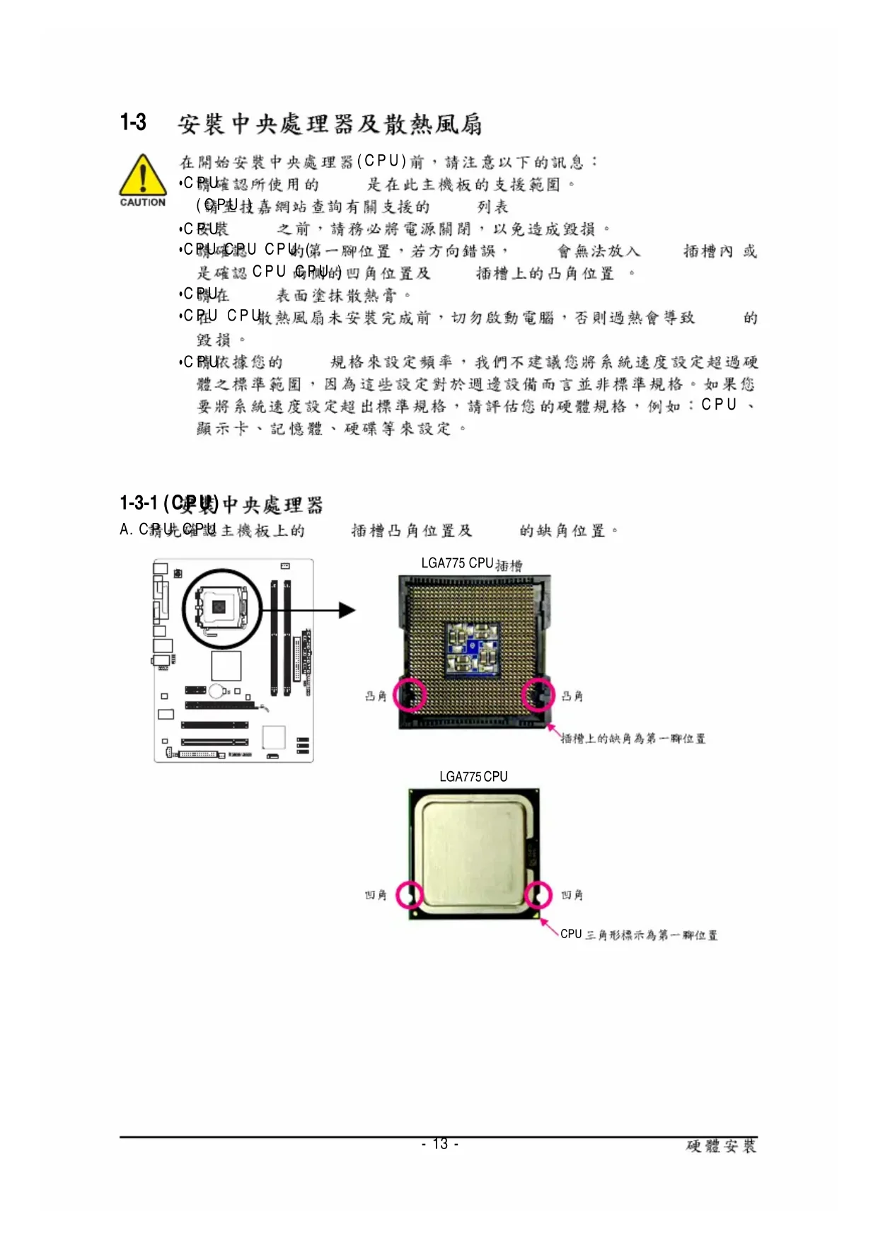
A. CPU CPU LGA775 CPU LGA775 CPU CPU- 14 -
CPU CPU CPU CPU CPU- 15 -
(Dual Channel Technology) BIOS
7.1 HD (High Definition )
16 PS_ON(soft On/Off)
CPU_FAN 4-pin SYS_FAN 3-pin
(Master/Slave) ( IDE )
HD (High Definition ) AC'97
(POST Power-On Self-
Integrated Peripherals
Integrated Peripherals ( )
Exit Without Saving ( )
Advanced Timing Control [Press Enter]
Mother Board Voltage Control
Voltage Types Normal Current
------------------------------------------------------------------
>>> CPU CPU Vcore 1.17500V [Auto]
Fine CPU Clock Ratio
x CPU Host Frequency (Mhz) 266
Performance Enhance [Standard]
CPU Clock Ratio (CPU )
CPU CPU CPU Fine CPU Clock Ratio (CPU )
CPU Frequency (CPU )
CPU Host Clock Control (CPU )
CPU Host Frequency (Mhz) (CPU )
CPU CPU Host Clock Control
Channel A Timing Settings [Press Enter]
Channel A Driving Settings [Press Enter]
Channel B Timing Settings [Press Enter]
Channel B Driving Settings [Press Enter]
Channel A Timing Settings
F5: Previous Values F6: Fail-Safe Defaults F7: Optimized Defaults
x Static tRead Value Auto
x tRD Phase0 Adjustment Auto
x tRD Phase1 Adjustment Auto
x tRD Phase2 Adjustment Auto
x tRD Phase3 Adjustment Auto
x Trd2rd(Different Rank) Auto
x DDR Write Training Auto
tRD Phase0 Adjustment
Auto ( ) 0-Normal 1-Advanced
tRD Phase1 Adjustment
Auto ( ) 0-Normal 1-Advanced
tRD Phase2 Adjustment
Auto ( ) 0-Normal 1-Advanced
tRD Phase3 Adjustment
Auto ( ) +800ps~-700ps
DIMM2 Clock Skew Control
Auto ( ) +800ps~-700ps
Channel A/B Driving Settings
CMOS Setup Utility-Copyright (C) 1984-2010 Award Software
Channel A Driving Settings
: Move Enter: Select +/-/PU/PD: Value F10: Save ESC: Exit F1: General Help
F5: Previous Values F6: Fail-Safe Defaults F7: Optimized Defaults
x Driving Strength Profile Auto
x Data Driving Pull-Up Level Auto
x Cmd Driving Pull-Up Level Auto
x Ctrl Driving Pull-Up Level Auto
x Clk Driving Pull-Up Level Auto
x Data Driving Pull-Down Level Auto
x Cmd Driving Pull-Down Level Auto
x Ctrl Driving Pull-Down Level Auto
x Clk Driving Pull-Down Level Auto
Driving Strength Profile
Auto ( ) 667MHz 800MHz 1066MHz OC-1200 OC-1333
Data Driving Pull-Up Level
Cmd Driving Pull-Up Level
Ctrl Driving Pull-Up Level
Clk Driving Pull-Up Level
Data Driving Pull-Down Level
Auto ( ) +8~-7BIOS - 40 -
Cmd Driving Pull-Down Level
Ctrl Driving Pull-Down Level
Clk Driving Pull-Down Level
IDE Channel 0 Master/Slave IDE/SATA
Time (hh:mm:ss) 18:25:04
IDE Channel 0 Master [None]
IDE Channel 0 Slave [None]
IDE Channel 2 Master [None]
IDE Channel 2 Slave [None]
IDE Channel 3 Master [None]
IDE Channel 3 Slave [None]
Drive A [1.44M, 3.5"]
Floppy 3 Mode Support [Disabled]
Halt On [All, But Keyboard]
All, But Keyboard ( )
First Boot Device [Floppy]
Second Boot Device [Hard Disk]
Third Boot Device [CDROM]
CPU Enhanced Halt (C1E)
C2/C2E State Support
CPU Thermal Monitor 2(TM2)
Delay For HDD (Secs) [0]
First / Second / Third Boot Device ( / / )
CPU Multi-Threading ( CPU )
CPU CPU Enabled CPU ( )
(buffer overflow) ( Enabled)
CPU Enhanced Halt (C1E) (Intel
CPU Enhanced Halt (C1E) ( CPU
C2/C2E State Support
CPU C2/C2E CPU ( Disabled)
CPU Thermal Monitor 2 (TM2) (Intel
CPU EIST Function (Intel
Virtualization Technology (Intel
Delay For HDD (Secs) ( )
Backup BIOS Image to HDD ( BIOS )
Init Display First [PCI]
PAVP Mode [PAVP Lite Mode]
PAVP Lite Mode [32MB]
x Paranoid PAVP Mode (32+96)128MB
PAVP Lite Mode (PAVP )
2-7 Integrated Peripherals ( )
SATA Disabled SATA Auto BIOS ( ) BIOS SATA Combined Enhanced Combined
Combined SATA PATA SATA PATA 2 IDE 2 SATA Enhanced SATA SATA Non-Combined SATA PATA IDE PATA IDE Set to ( IDE )
Ch.0 Master/Slave IDE Ch. 0 Master/Slave ( )
Ch.1 Master/Slave IDE Ch. 1 Master/Slave
Disabled SATA Non-Combined IDE SATA Port 0/2 Set to ( SATA 0/2 )
PATA IDE Set to PATA IDE Set to Ch. 1
Master/Slave Ch. 0 Master/Slave
SATA Port 1/3 Set to ( SATA 1/3 )
PATA IDE Set to PATA IDE Set to Ch. 0
Master/Slave Ch. 1 Master/Slave
CMOS Setup Utility-Copyright (C) 1984-2010 Award Software
Integrated Peripherals
On-Chip Primary PCI IDE [Enabled]
On-Chip SATA Mode [Auto]
x PATA IDE Set to Ch.0 Master/Slave
SATA Port 0/2 Set to Ch.2 Master/Slave
SATA Port 1/3 Set to Ch.3 Master/Slave
Onboard H/W LAN [Enabled]
SMART LAN [Press Enter]
Onboard LAN Boot ROM [Disabled]
Onboard Serial Port 1 [3F8/IRQ4]
Onboard Serial Port 2 [2F8/IRQ3]
Onboard Parallel Port [378/IRQ7]
Parallel Port Mode [SPP]
Start detecting at Port
Part1-2 Status = Open / Length = 0m
Part3-6 Status = Open / Length = 0m
Part4-5 Status = Open / Length = 0m
Part7-8 Status = Open / Length = 0m
: Move Enter: Select +/-/PU/PD: Value F10: Save ESC: Exit F1: General Help
F5: Previous Values F6: Fail-Safe Defaults F7: Optimized Defaults
Start detecting at Port
Cable Length 10m Cable
length less than 10M MS-DOS 10/100 Mbps
Windows LAN Boot ROM Gigabit hub 10/100/
1000 Mbps- 49 - BIOS
hub Status Short Length
Part1-2 Status = Short / Length = 2m
EPP EPP (Enhanced Parallel Port)
ECP ECP (Extended Capabilities Port)
ECP+EPP EPP ECP USB 1.0 Controller ( USB 1.0 )
USB Keyboard Support ( USB )
MS-DOS USB ( Disabled)
USB Mouse Support ( USB )
Power Management Setup
ACPI Suspend Type [S3(STR)]
Soft-Off by PWR-BTTN [Instant-Off]
PME Event Wake Up [Enabled]
Power On by Ring [Enabled]
Resume by Alarm [Disabled]
x Date (of Month) Alarm Everyday
Soft-Off by PWR-BTTN ( )
Power On by Ring ( )
7/Vista- 51 - BIOS Resume by Alarm ( )
64-bit mode HPET Support
Power On By Mouse ( )
+5VSB 1 ATX Disabled ( )
Power On By Keyboard ( )
Power On by Keyboard Password
2-10 PC Health Status ( )
Current Voltage(V) Vcore / DDR18V / +3.3V / +12V ( )
Current CPU Temperature ( /CPU )
CPU Current CPU/SYSTEM FAN Speed (RPM) ( )
CPU Warning Temperature (CPU )
CPU CPU Disabled ( CPU
CPU Smart FAN Control (CPU )
CPU Disabled CPU Enabled CPU CPU EasyTune ( )
CMOS Setup Utility-Copyright (C) 1984-2010 Award Software
Integrated Peripherals
Integrated Peripherals
2-13 Set Supervisor/User Password ( / )
Integrated Peripherals
2-15 Exit Without Saving ( )
Integrated Peripherals
Save to CMOS and EXIT (Y/N)? Y CMOS Setup Utility-Copyright (C) 1984-2010 Award Software
Integrated Peripherals
Quit Without Saving (Y/N)? N- 57 -
C. Xpress Recovery2 (Backup)
BACKUP Xpress Recovery2- 63 -
D. Xpress Recovery2 (Restore)
RESTORE E. Xpress Recovery2 (Remove)
REMOVE F. Xpress Recovery2
BIOS BIOS "Are you sure
Update BIOS from Drive
Update BIOS from Drive
Enter : Run :Move ESC:Reset F10:Power Off
!! Copy BIOS completed - Pass !!
Please press any key to continue- 66 -
Save & Exit Setup <Y> CMOS BIOS BIOS BIOS
Integrated Peripherals
2. BIOS Update BIOS from File
EasyTune 6 CPU CPU EasyTune 6
Graphics ATI NVIDIA Smart CPU Advanced CPU CPU HW Monitor
4-4 (Easy Energy Saver)
2 Duo/ Pentium Dual-Core/ Celeron Dual-Core/ Celeron 400
BIOS CPU Enhanced Halt (C1E)
CPU EIST Function Enabled
Enable Incoming Folder ...
Device Scan Time (sec.)
(High Definition Audio)
S/PDIF S/PDIF S/PDIF S/PDIF S/PDIF S/PDIF S/PDIF S/PDIFS/PDIF S/PDIF
(S/PDIF + ) ( ) S/PDIF S/PDIF- 79 -
B-2. S/PDIF Digital Output
A Service Pack 1 Service Pack 2 (
UAA Bus Driver for High Definition Audio
High Definition Audio Bus
Microsoft UAA Bus Driver for High Definition Audio
A CPU CPU CPU_FAN ATX 12V CPU
Restriction of the use of Certain Hazardous Substances in Electrical and
Electronic Equipment, RoHS) WEEE ( Waste Electrical and Electronic
G.B.T. INC. (U.S.A.)
G.B.T. TECHNOLOGY TRADING GMBH
Representative Office Of GIGA-BYTE Technology Co., Ltd.
Representative Office Of GIGA-BYTE Technology Co., Ltd.
Moscow Representative Office Of GIGA-BYTE Technology
Representative Office Of GIGA-BYTE Technology Co., Ltd.
Representative Office Of GIGA-BYTE Technology Co., Ltd.