1173200 - Lighting BRENNENSTUHL - Free user manual and instructions
Find the device manual for free 1173200 BRENNENSTUHL in PDF.
| Brand | Brennenstuhl |
| Model | 1173200 (Brobusta RL) |
| Product type | Construction light with integrated sockets |
| Bulb | E27, max. 60 W (energy-saving bulb recommended) |
| Number of sockets | 2 |
| Total socket power | 3500 W |
| Supply voltage | 220-240 V ~ 50/60 Hz |
| Protection rating | IP54 (dust and water splash protected) |
| Protection class | I |
| Cable length | 5 m (H07RN-F 3G1,5) |
| Cable material | Heavy rubber (H07RN-F) |
| Usage | Indoor and outdoor (IP54) |
| Main functions | Adjustable lamp, on/off switch, suspension hook, tripod mount (2x M6) |
| Maintenance | Clean with a dry, lint-free cloth; do not use solvents or immerse |
| Safety | Disconnect before any intervention; do not cover; use a bulb of correct wattage; replace damaged cover |
| Disposal | Do not dispose of with household waste; recycle according to WEEE directive |
| Manufacturer | Brennenstuhl GmbH & Co. KG, www.brennenstuhl.com |
Frequently Asked Questions - 1173200 BRENNENSTUHL
User questions about 1173200 BRENNENSTUHL
0 question about this device. Answer the ones you know or ask your own.
Ask a new question about this device
Download the instructions for your Lighting in PDF format for free! Find your manual 1173200 - BRENNENSTUHL and take your electronic device back in hand. On this page are published all the documents necessary for the use of your device. 1173200 by BRENNENSTUHL.
USER MANUAL 1173200 BRENNENSTUHL
natural_image
Technical line drawing of two mechanical components with a close-up inset showing a screw inserted into a housing (no text or symbols)Abb. 1a Abb. 1b
natural_image
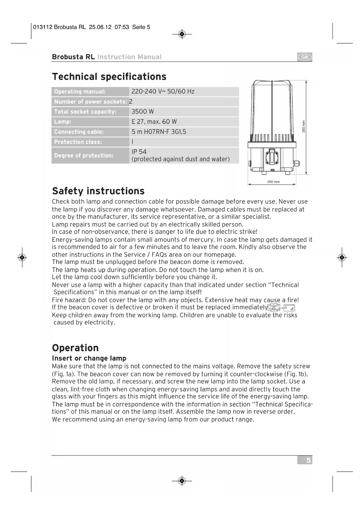
Four technical illustrations of industrial sensors or equipment, including a cylindrical device, a mechanical component, a tripod-mounted sensor, and a vertical cylindrical device (no visible text or symbols)Technical specifications
| Operating manual: | 220-240 V~ 50/60 Hz |
| Number of power sockets: | 2 |
| Total socket capacity: | 3500 W |
| Lamp: | E 27, max. 60 W |
| Connecting cable: | 5 m H07RN-F 3G1,5 |
| Protection class: | I |
| Degree of protection: | IP 54(protected against dust and water) |
Safety instructions
Check both lamp and connection cable for possible damage before every use. Never use the lamp if you discover any damage whatsoever. Damaged cables must be replaced at once by the manufacturer, its service representative, or a similar specialist.
Lamp repairs must be carried out by an electrically skilled person.
In case of non-observance, there is danger to life due to electric strike!
Energy-saving lamps contain small amounts of mercury. In case the lamp gets damaged it is recommended to air for a few minutes and to leave the room. Kindly also observe the other instructions in the Service / FAQs area on our homepage.
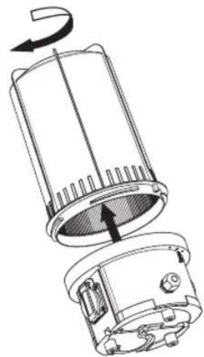
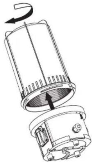
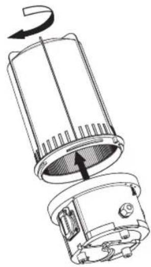
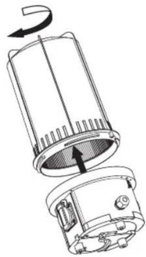
The lamp must be unplugged before the beacon dome is removed.
The lamp heats up during operation. Do not touch the lamp when it is on.
Let the lamp cool down sufficiently before you change it.
Never use a lamp with a higher capacity than that indicated under section "Technical Specifications" in this manual or on the lamp itself!
Fire hazard: Do not cover the lamp with any objects. Extensive heat may cause a fire! If the beacon cover is defective or broken it must be replaced immediately.
Keep children away from the working lamp. Children are unable to evaluate the risks caused by electricity.
Operation
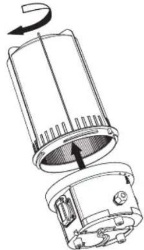
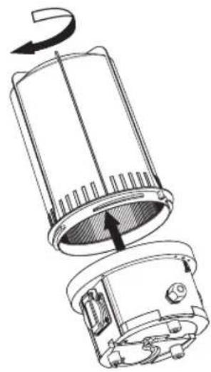
Insert or change lamp
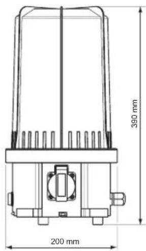
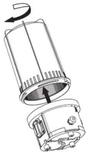
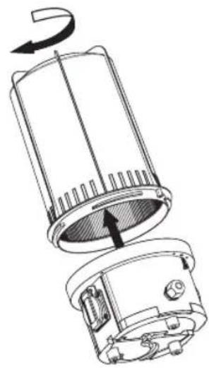
Make sure that the lamp is not connected to the mains voltage. Remove the safety screw (Fig. 1a). The beacon cover can now be removed by turning it counter-clockwise (Fig. 1b). Remove the old lamp, if necessary, and screw the new lamp into the lamp socket. Use a clean, lint-free cloth when changing energy-saving lamps and avoid directly touch the glass with your fingers as this might influence the service life of the energy-saving lamp. The lamp must be in correspondence with the information in section "Technical Specifications" of this manual or on the lamp itself. Assemble the lamp now in reverse order. We recommend using an energy-saving lamp from our product range.

Brobusta RL Instruction Manual
natural_image
Technical line drawing of a mechanical component with an inset showing a close-up detail (no text or symbols)Fig. 1a Fig. 1b

natural_image
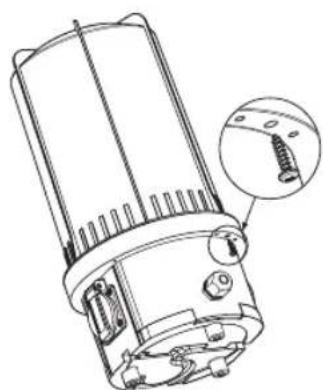
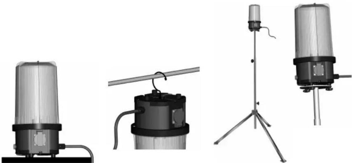
Technical line drawing of a device with a rotating top component and internal components (no text or symbols)Information on possible fields of application
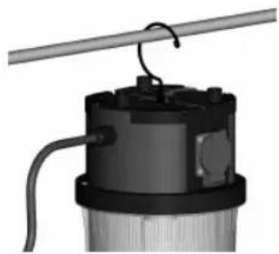
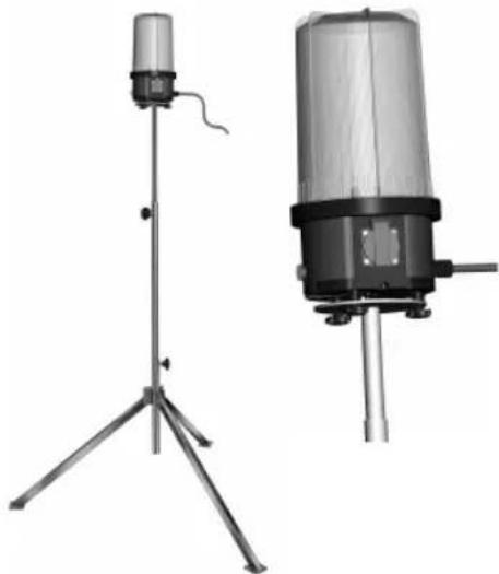
The lamp can be used standing, hanging or mounted on a tripod.
Position the lamp in a dry and plain area (Fig. 2).
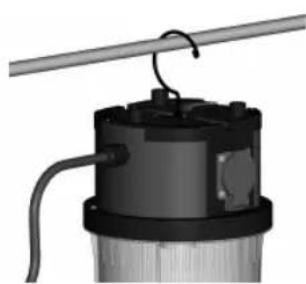
The suspension hook is on the bottom of the lamp. When hanging up the lamp, pay attention that the lamp is properly fixed and cannot fall off (Fig. 3). Click the suspension hook back into place on the bottom of the lamp when you do not need the lamp any more.
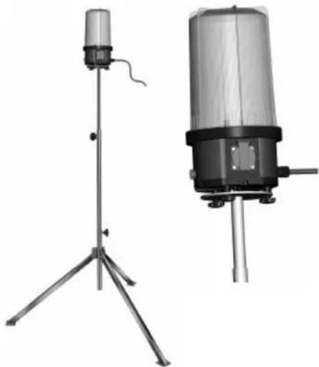
The lamp can be mounted on a tripod on the feet at the bottom of the lamp by means of two adequate bolts (M6 thread) (Fig. 4). It is essential that the tripod stands in a stable position.
natural_image
Four technical illustrations of industrial sensors or measurement devices, including a cylindrical device and three vertical-mounted sensors with tripod stands (no text or symbols visible)The lamp can be switched on or off by means of the switch on the side. The power sockets are ready for operation in any position.
Cleaning and maintenance
The lamp does not have any parts that need to be maintained by the user. Never try to open the lamp except for a change of lamp, see section "Insert or change of the lamp". Unplug the lamp from the mains voltage before any cleaning activities. Clean the lamp regularly with a dry, lint-free cloth. To remove more stubborn dirt, a slightly moistened cloth can be used. Do not use any solvents, corrosive cleaning agents or similar which might damage the lamp. For reasons of electrical safety the lamp must never be cleaned with water or other liquids or even be dipped into water.
Disposal

Do not throw any electrical devices into your household waste!
According to the European Directive 2002 / 96 / EC on waste electrical and electronic equipment (WEEE) and implementation into national law, all WEEE have to be collected separately and sent for an environmentally sound recycling.
Currently applicable instructions for disposal can be obtained from your municipality.
Energy-saving lamps must not be disposed of in household waste. Please dispose the lamps correctly via your local collection point.
Service address / Manufacturer
For further information we recommend to visit the Service/FAQ area on our homepage under www.brennenstuhl.com.

natural_image
Technical illustration of two mechanical components with a magnified inset showing a screw inserted into a housing (no text or symbols present)Fig. 1a Fig. 1b
natural_image
Four technical illustrations of industrial sensors or equipment, including a cylindrical device and three vertical stands with a tripod stand (no text or symbols visible)natural_image
Technical line drawing of two mechanical components with a magnified inset showing a screw inserted into a housing (no text or symbols)Afb. 1a Afb. 1b
natural_image
Four technical illustrations of industrial sensors or measurement devices, including a cylindrical device and three vertical-mounted devices with tripod stands (no text or symbols visible)natural_image
Technical line drawing of a mechanical component with an inset showing a screw inserted into a housing (no text or symbols present)Imm. 1a Imm. 1b
natural_image
Technical line drawing of a device with internal components and rotation arrow (no text or symbols)natural_image
Exterior view of a cylindrical industrial sensor or sensor device with a transparent top and black base (no visible text or symbols)Imm. 2 Imm. 3
natural_image
3D rendering of a mechanical device with a coiled rod and attached housing (no visible text or symbols)Imm. 4
natural_image
Two scientific instruments or measurement devices on tripod stands, one with a cylindrical sensor and the other a cylindrical device (no visible text or symbols)
natural_image
Technical line drawing of a mechanical component with an inset close-up showing a threaded fastener (no text or symbols present)Bild 1a Bild 1b
natural_image
Technical line drawing of a mechanical device with an arrow indicating rotation (no text or symbols present)Avsedd användning
natural_image
Exterior view of a transparent cylindrical device mounted on a base with cables (no visible text or symbols)III.2
natural_image
Mechanical component with attached rod and wiring, no visible text or symbolsIII. 3
natural_image
Two scientific instruments: a tripod-mounted sensor and a cylindrical device with a base, both without any visible text or symbols.III. 4
natural_image
Technical line drawing of a mechanical component with an inset showing a screw inserted into a housing (no text or symbols present)Fig. 1a
natural_image
Technical line drawing of a device with internal components and a rotation arrow (no text or symbols)Fig. 1b
natural_image
Technical illustration of two mechanical components with a close-up inset showing a screw inserted into a housing (no text or symbols present)Ilustr. 1a Ilustr. 1b
natural_image
Four technical illustrations of industrial sensors or measurement devices, including a cylindrical device and three vertical-mounted devices with no visible text or symbols.Ilustr. 2 Ilustr. 3 Ilustr. 4
natural_image
Technical line drawing of a mechanical component with an inset close-up showing a threaded fastener (no text or symbols present)Obr. 1a Obr. 1b

natural_image
Technical line drawing of a device with a rotating top component and internal components (no text or symbols)natural_image
Four technical illustrations of industrial sensors or equipment, including a cylindrical device and three vertical stands with a tripod stand (no text or symbols visible)Obr. 2 Obr. 3 Obr. 4
natural_image
Technical line drawing of a mechanical component with an inset showing a screw inserted (no text or symbols present)1a. ábra 1b. ábra

natural_image
Technical line drawing of a cylindrical device with internal components and a rotation arrow indicating rotational motion (no text or symbols)Használati utasítás
natural_image
Four technical illustrations of industrial sensors or equipment, including a cylindrical device and three vertical stands with a tripod stand (no text or symbols visible)natural_image
Technical line drawing of a mechanical component with an inset showing a screw inserted into a housing (no text or symbols present)Resim 1a Resim 1b
natural_image
Technical line drawing of a mechanical device with internal components and rotation arrow (no text or symbols)natural_image
Four technical illustrations of industrial sensors or equipment, including a cylindrical device and three vertical stands with a tripod stand (no text or symbols visible)natural_image
Technical line drawing of a mechanical component with an inset showing a screw inserted into a housing (no text or symbols present)Kuva 1a Kuva 1b
natural_image
Technical line drawing of a mechanical device with internal components and rotation arrow (no text or symbols)natural_image
Four technical illustrations of industrial sensors or measurement devices, including a cylindrical device, a mechanical component, a tripod-mounted sensor, and a vertical cylindrical device (no visible text or symbols)natural_image
Technical line drawing of a mechanical component with an inset showing a screw inserted into a housing (no text or symbols present)Εικ. 1α Εικ. 1β
natural_image
Technical line drawing of a device with internal components and a rotation arrow (no text or symbols)natural_image
Four technical illustrations of industrial sensors or equipment, including a cylindrical device and three vertical-mounted devices with a tripod stand (no visible text or symbols)natural_image
Technical line drawing of two mechanical components with a magnified inset showing a screw inserted into a housing (no text or symbols)Рис. 1а Рис. 16
natural_image
Four technical diagrams of industrial sensors or equipment, including a cylindrical device and three vertical stands with a tripod stand (no text or symbols visible)natural_image
Technical line drawing of a mechanical component with an inset close-up showing a threaded screw (no text or symbols present)Fig. 1a Fig. 1b

natural_image
Technical line drawing of a mechanical device with internal components and rotation arrow (no text or symbols)natural_image
Four technical illustrations of industrial sensors or measurement devices, including a cylindrical device and three vertical-mounted devices with no visible text or symbols.natural_image
Technical line drawing of a mechanical component with an inset close-up showing a threaded screw (no text or symbols present)Joon. 1a Joon. 1b
natural_image
Technical line drawing of a mechanical device with an arrow indicating rotation (no text or symbols present)natural_image
Four technical illustrations of industrial sensors or equipment, including a cylindrical device and three vertical stands with a tripod stand (no text or symbols visible)Joon. 2 Joon. 3 Joon. 4
natural_image
Technical line drawing of a mechanical component with an inset showing a screw inserted (no text or symbols present)Obr. 1a Obr. 1b

natural_image
Technical line drawing of a mechanical device with an arrow indicating rotation (no text or symbols present)Pokyny k možnostiam používania
natural_image
Four technical illustrations of industrial sensors or measurement devices, including a cylindrical device and three vertical stands with a tripod stand (no text or symbols visible)Obr. 2 Obr. 3 Obr. 4
natural_image
Four technical illustrations of industrial sensors or equipment, including a cylindrical device and three vertical-mounted devices with a tripod stand (no text or symbols visible)natural_image
Technical line drawing of a mechanical component with an inset close-up showing a threaded fastener (no text or symbols present)1a pav. 1b pav.
natural_image
Technical line drawing of a device with a rotating top component and internal components (no text or symbols)natural_image
Four different types of industrial sensors or equipment, including a cylindrical device and three vertical stands with a tripod-mounted sensor (no visible text or symbols)2 pav. 3 pav. 4 pav.