LU10142 - Basket SIEMENS - Free user manual and instructions
Find the device manual for free LU10142 SIEMENS in PDF.
User questions about LU10142 SIEMENS
0 question about this device. Answer the ones you know or ask your own.
Ask a new question about this device
Download the instructions for your Basket in PDF format for free! Find your manual LU10142 - SIEMENS and take your electronic device back in hand. On this page are published all the documents necessary for the use of your device. LU10142 by SIEMENS.
USER MANUAL LU10142 SIEMENS
natural_image
3D rendering of a rectangular metal enclosure with a grid-patterned interior (no text or symbols)de Seite 3–15
es página 68 - 80
en page 16 - 28
pt página 81 - 93
fr page 29 - 41
natural_image
Diagram of a perforated metal panel with circular arrows indicating flow or movement, showing internal structure and surface texture (no text or symbols)natural_image
Diagram of a mechanical device with two circular components and an arrow indicating direction (no text or symbols)natural_image
Illustration of a hand holding a document or scroll, with no visible text or symbols.natural_image
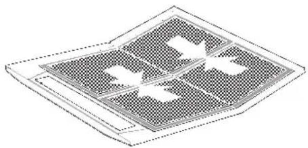
Isometric view of a grid-patterned surface with three white rectangular cutouts (no text or symbols)Aktivkohlefilter:
text_image
Diagram illustrating a mechanical assembly or inspection process with labeled components and magnified views of the main component.text_image
Diagram illustrating airflow or ventilation process in a refrigerated room, with labeled components and directional arrows indicating flow direction.natural_image
Illustration of a robotic arm interacting with a mechanical component (no text or symbols visible)natural_image
Diagram of a mechanical component with internal components and directional arrows indicating motion (no text or symbols)natural_image
Illustration of a hand using a tool to press or install a circular component on a base (no text or symbols visible)natural_image
Illustration of a hand using a tool to cut a circular object, possibly a mechanical component or device (no text or symbols visible)natural_image
Illustration of a hand holding a screwdriver inside a device with a circular component on top (no text or symbols)natural_image
Illustration of a hand using a tool to press or install a mechanical component, with no visible text or symbols.natural_image
Illustration of a hand using a tool to cut a circular object, no text or symbols presentnatural_image
Diagram showing airflow or heat transfer between a rectangular block and a brick wall, with arrows indicating direction (no text or symbols)text_image
Technical diagram showing a mechanical assembly with labeled components and cross-sectional viewsnatural_image
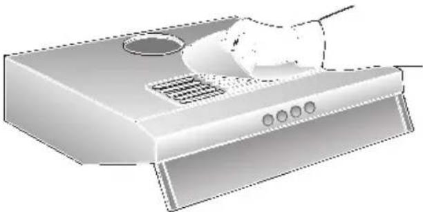
Illustration of a kitchen fan with a hand holding a tray (no text or symbols)Operating instructions:
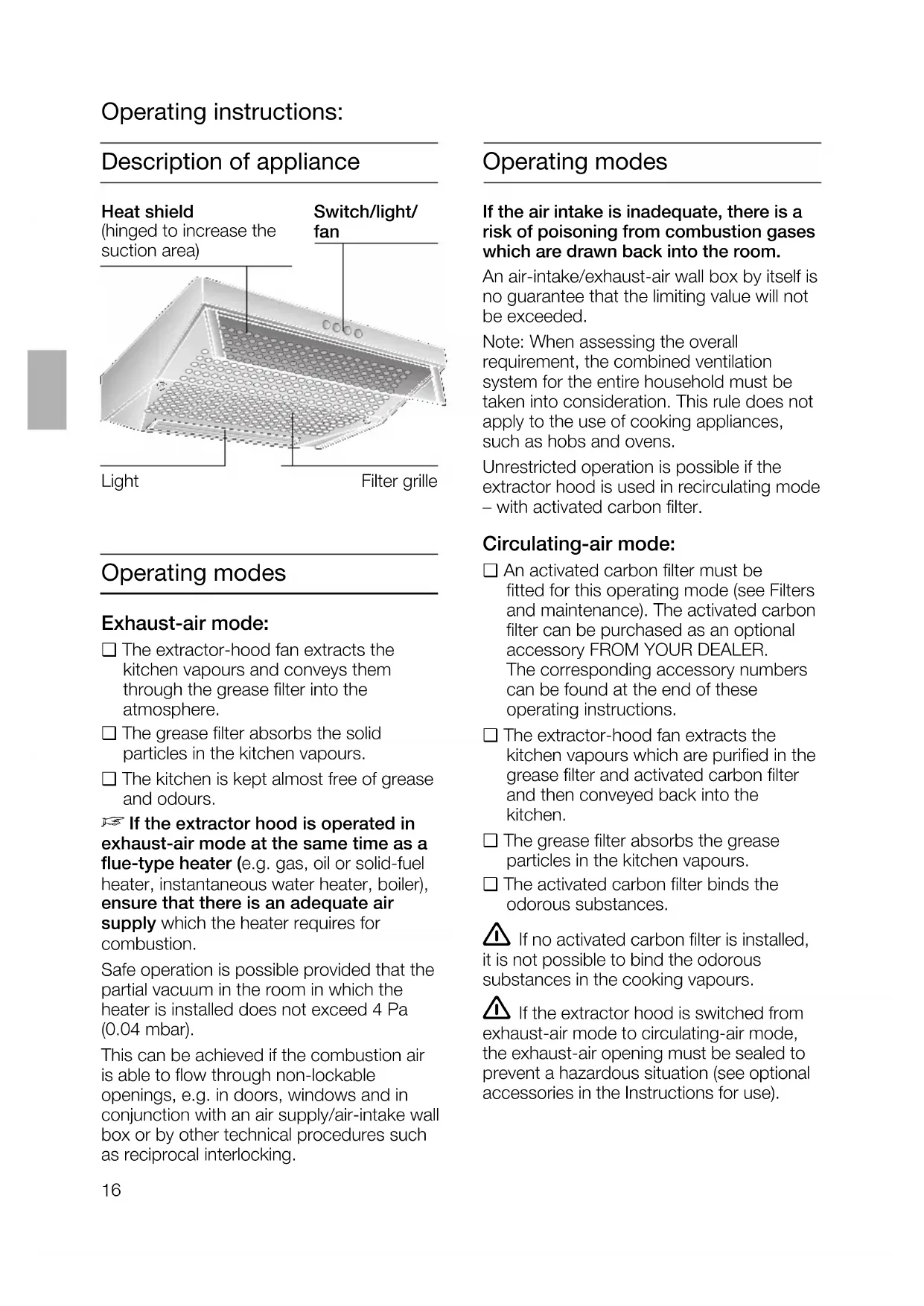
Description of appliance
Heat shield
(hinged to increase the suction area)
Switch/light/fan
text_image
Light Filter grilleOperating modes
Exhaust-air mode:
☐ The extractor-hood fan extracts the kitchen vapours and conveys them through the grease filter into the atmosphere.
☐ The grease filter absorbs the solid particles in the kitchen vapours.
☐ The kitchen is kept almost free of grease and odours.
If the extractor hood is operated in exhaust-air mode at the same time as a flue-type heater (e.g. gas, oil or solid-fuel heater, instantaneous water heater, boiler), ensure that there is an adequate air supply which the heater requires for combustion.
Safe operation is possible provided that the partial vacuum in the room in which the heater is installed does not exceed 4 Pa (0.04 mbar).
This can be achieved if the combustion air is able to flow through non-lockable openings, e.g. in doors, windows and in conjunction with an air supply/air-intake wall box or by other technical procedures such as reciprocal interlocking.
Operating modes
If the air intake is inadequate, there is a risk of poisoning from combustion gases which are drawn back into the room.
An air-intake/exhaust-air wall box by itself is no guarantee that the limiting value will not be exceeded.
Note: When assessing the overall requirement, the combined ventilation system for the entire household must be taken into consideration. This rule does not apply to the use of cooking appliances, such as hobs and ovens.
Unrestricted operation is possible if the extractor hood is used in recirculating mode – with activated carbon filter.
Circulating-air mode:
☐ An activated carbon filter must be fitted for this operating mode (see Filters and maintenance). The activated carbon filter can be purchased as an optional accessory FROM YOUR DEALER. The corresponding accessory numbers can be found at the end of these operating instructions.
☐ The extractor-hood fan extracts the kitchen vapours which are purified in the grease filter and activated carbon filter and then conveyed back into the kitchen.
☐ The grease filter absorbs the grease particles in the kitchen vapours.
☐ The activated carbon filter binds the odorous substances.
⚠️ If no activated carbon filter is installed, it is not possible to bind the odorous substances in the cooking vapours.
⚠️ If the extractor hood is switched from exhaust-air mode to circulating-air mode, the exhaust-air opening must be sealed to prevent a hazardous situation (see optional accessories in the Instructions for use).
Before using for the first time
Important notes:
☐ The Instructions for Use apply to several versions of this appliance. Accordingly, you may find descriptions of individual features that do not apply to your specific appliance.
☐ This extractor hood complies with all relevant safety regulations.
Repairs should be carried out by qualified technicians only.
Improper repairs may put the user at considerable risk.
⚠️ Do not use the appliance if damaged.
⚠ The appliance is not intended for use by young children or infirmed persons without supervision.
Young children should be supervised to ensure they do not play with the appliance.
⚠️ If the connecting cable for this appliance is damaged, the cable must be replaced by the manufacturer or his customer service or a similarly qualified person in order to prevent serious injury to the user.
⚠ The appliance may be connected to the mains by a qualified technician only.
⚠ Dispose of packaging materials properly (see Installation instructions).
⚠ This extractor hood is designed for domestic use only.
Light bulbs must always be fitted when the extractor hood is in use.
⚠️ Defective bulbs should be replaced immediately to prevent the remaining bulbs from overloading.
⚠️ Never operate the extractor hood without a grease filter.
⚠️ Overheated fat or oil can easily catch fire.
If you are cooking with fat or oil, e.g. chips, etc., never leave the cooker unattended.
☐ Before using your appliance for the first time, please read these Instructions for Use carefully. They contain important information concerning your personal safety as well as on use and care of the appliance.
☐ Please retain the operating and installation instructions for a subsequent owner.
⚠ Do not flambé food directly under the extractor hood.
! Risk of grease filter catching fire due to flames.
⚠️ The hotplates must always be covered with a utensil.
⚠️ Restrictions apply to the use of the extractor hood over a solid-fuel burner (coal, wood, etc.). (See Installation instructions).
Gas hobs / Gas cookers
Do not use all the gas hotplates simultaneously for a prolonged period (max. 15 minutes) at maximum thermal load, otherwise there is a risk of burns if the housing surfaces are touched or a risk of damage to the extractor hood. If the extractor hood is situated over a gas hob, operate the hood at maximum setting if three or more gas hotplates are operated simultaneously.
Operating the extractor hood

Cooking vapours are best eliminated
□ Switching on the extractor hood when you start cooking.
☐ Only switching off the extractor hood a few minutes after you have finished cooking.
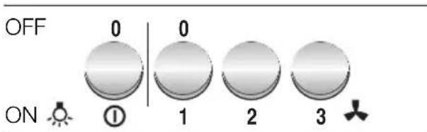
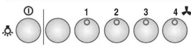
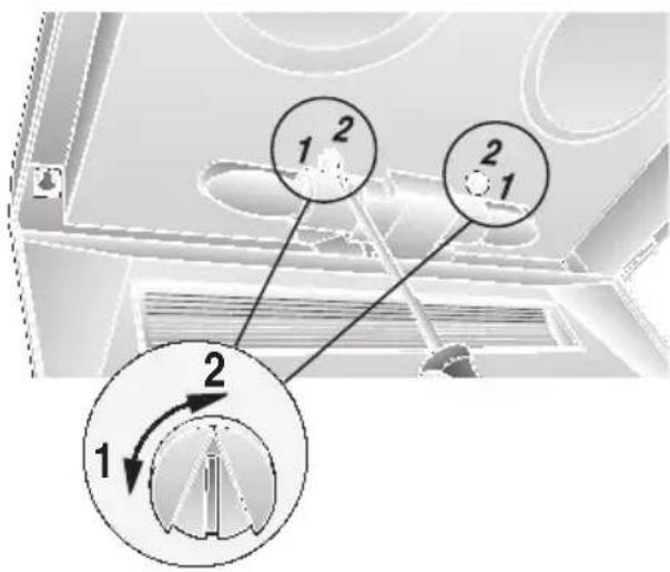
| Light | Fan settings | |||
| Off | 0 | 1 | Low | |
| On | 1 | 0 | Off | |
| 2 | High | |||
Light
text_image
OFF 0 0 ON ⚙① 1 2 3Light
ON / OFF
Fan settings
Intensive setting
text_image
① 1 2 3 4Filters and maintenance
Different grease filters can be used to absorb the grease particles in the kitchen vapours.
Fleece grease filter:
The filter mat consists of highly flammable material.
Warning:
A build up of greasy residue increases flammability, and the function of the extractor hood may be impaired.
Important:
Replace the fleece grease filter in good time, otherwise there is a risk of fire from the heat which accumulates during deep-fat frying or roasting.
Replacing the fleece grease filter:
☐ During normal operation (daily 1 to 2 hours) the fleece grease filter must be replaced every 8 to 10 weeks.
Replace printed fleece grease filters at the latest when the coloured print dissolves.
□ Use only original filters.
These comply with the safety regulations and ensure optimum function.
Disposal of the old fleece grease filter:
☐ Fleece grease filters do not contain any harmful substances. They can be disposed of as bio-degradable waste.
Filters and maintenance
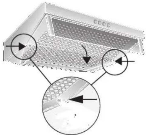
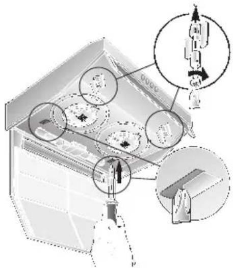
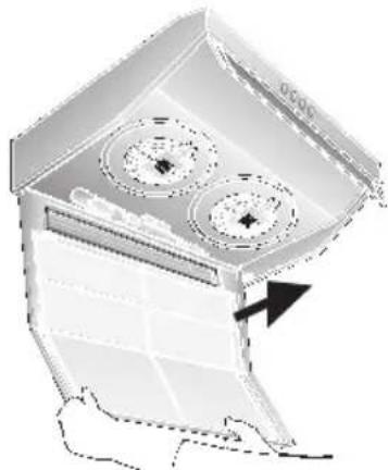
Removing and installing the metal filter:
- Press in the interlocks on the left and right sides of the filter grille.
natural_image
Diagram of a perforated metal tray with circular arrows indicating flow or movement, showing internal structure and surface texture (no text or symbols)- Remove the filter grille.
natural_image
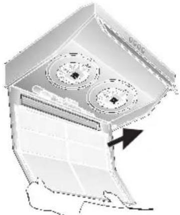
Diagram of a mechanical device with two circular components and an arrow indicating direction (no text or symbols)- Remove the wire grille and the saturated filter mats.
natural_image
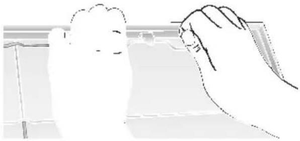
Illustration of a hand holding a small object, possibly a tool or device, with no visible text or symbols.-
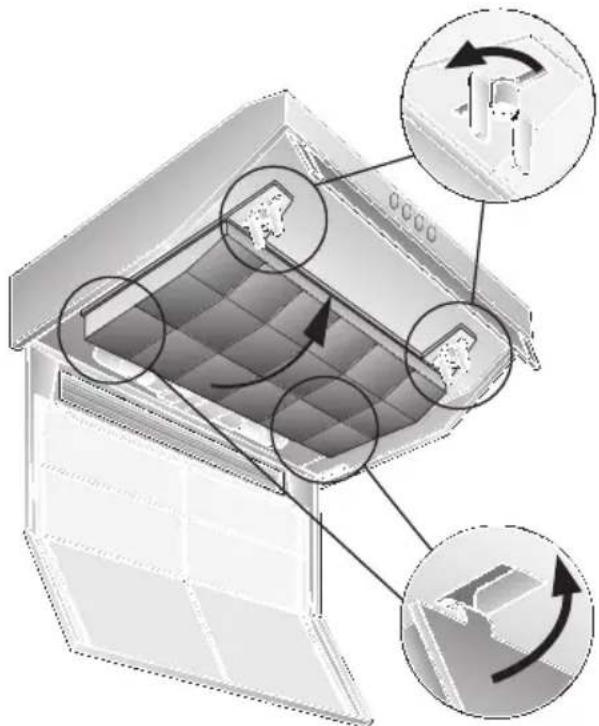
Clean the filter grille and insert a new filter mat.
-
Clamp the filter mat with the wire grille.
-
Re-insert the filter grille.
⚠ The interlocks must lock into position on the left and right sides.
Metal grease filter:
The filter mats consist of non-flammable material.
Warning:
A build up of greasy residue increases flammability, and the function of the extractor hood may be impaired.
Important:
Replace the metal grease filter in good time, otherwise there is a risk of fire from the heat which accumulates during deep-fat frying or roasting.
Cleaning the metal grease filter:
☐ During normal operation (daily 1 to 2 hours) the metal grease filter must be replaced every 8 to 10 weeks.
☐ The metal grease filter can be cleaned in the dishwasher. Slight discoloration may occur.
Important:
Do not clean heavily saturated metal grease filters with other dishes.
☐ If cleaning by hand, soak the grease filters in a hot soapy solution. Then brush off any residual grease, rinse thoroughly and leave to dry.
□ Use only original filters.
These ensure optimum function.
Filters and maintenance
Removing and installing the metal filter
(See details for removing/inserting the fleece filter):
- Clean the filter grille and the filter mats.
- Re-insert the cleaned filter mats and clamp them with the wire grille. Ensure that there is no gap in the middle.
natural_image
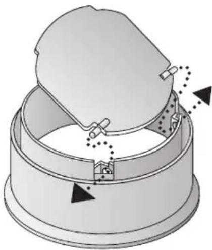
Isometric view of a grid-patterned surface with four rectangular cutouts (no text or symbols)Activated carbon filter:
For binding the odorous substances in circulating-air mode.
(See details for removing/inserting the fleece filter.)
-
Insert the screws through the wing nuts and sleeves and screw the screws into the left and right sides of the intermediate base (required only during the initial installation). Screws, wing nuts and sleeves are enclosed with the activated carbon filter –.
-
Using a screwdriver or similar tool, press the two lugs on the housing inwards (required only during the initial installation).
text_image
Diagram illustrating a mechanical assembly or inspection process with labeled components and directional arrows indicating movement or assembly.- Insert the activated carbon filter at the rear, fold up and lock into position on the left and right with the wing nuts.
The lugs on the left and right sides of the activated carbon filter are folded in for the 50 cm wide extractor hood. They must be folded up for the 60 cm and 90 cm wide extractor hoods.
text_image
Diagram illustrating airflow or movement in a storage or ventilation system with labeled components and directional arrowsReplacing the activated carbon filter:
☐ During normal operation (daily 1 to 2 hours) the activated carbon filter must be replaced approximately 1 x year.
☐ The activated carbon filter can be purchased FROM YOUR DEALER (see Optional accessories).
□ Use only original filters.
These ensure optimum function.
Disposal of the old activated carbon filter:
□ Activated carbon filters do not contain any harmful substances. They can be disposed of as residual waste.
Cleaning and care
Isolate the extractor hood by pulling out the mains plug or switching off the fuse.
☐ When cleaning the grease filters, remove grease deposits from accessible parts of the housing. This prevents the risk of fire and ensures that the extractor hood continues operating at maximum efficiency.
□ Clean the extractor hood with a hot soap solution or a mild window cleaner.
☐ Do not scrape off dried-on dirt but wipe off with a damp cloth.
☐ Do not use scouring agents or abrasive sponges.
☐ Note: Do not use alcohol (spirit) on plastic surfaces, as dull marks may appear.
Caution: Ensure that the kitchen is adequately ventilated. Avoid naked flames!
⚠ Clean the operating buttons with a mild soapy solution and a soft, damp cloth only. Do not use stainless-steel cleaner to clean the operating buttons.
Stainless steel surfaces:
□ Use a mild non-abrasive stainless steel cleaner.
□ Clean the surface in the same direction as it has been ground and polished.
⚠ Do not use any of the following to clean stainless steel surfaces: abrasive sponges, cleaning agents containing sand, soda, acid or chloride!
Aluminium and plastic surfaces:
☐ Use a soft, non-linting window cloth or micro-fibre cloth.
☐ Do not use dry cloths.
☐ Use a mild window cleaning agent.
☐ Do not use aggressive, acidic or caustic cleaners.
☐ Do not use abrasive agents.
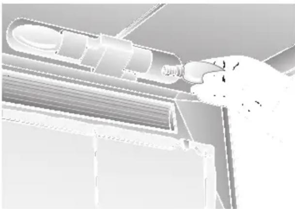
Replacing the light bulbs
- Switch off the extractor hood and isolate the extractor hood by pulling out the mains plug or switching off the fuse.
- Remove the grease filter (see Filters and maintenance).
- Replace the bulb (standard filament bulb, max 40 W, E14 bulb holder).
natural_image
Illustration of a robotic arm interacting with a mechanical component (no text or symbols visible)- Re-insert the grease filters.
- Reconnect the power by inserting the mains plug or by switching on the fuse.
Malfunctions
Please contact customer service regarding any queries or malfunctions.
(See customer-service directory).
When calling, please quote:
E-No.
FD
Enter the numbers in the above box. The numbers can be found on the rating plate – remove the grease filter inside the extractor hood to reveal the rating plate.
Important information
⚠️ Old appliances are not worthless rubbish. Valuable raw materials can be reclaimed by recycling old appliances. Before disposing of your old appliance, render it unusable.
⚠️ You received your new appliance in a protective shipping carton. All packaging materials are environmentally friendly and recyclable. Please contribute to a better environment by disposing of packaging materials in an environmentally-friendly manner.
Please ask your dealer or inquire at your local authority about current means of disposal.
⚠ The extractor hood can be used in exhaust air or circulating air mode.
⚠️ Always mount the extractor hood over the centre of the hob.
⚠️ Minimum distance between electric hob and bottom edge of extractor hood: 650 mm, Fig. 1.
⚠ The extractor hood must not be installed over a solid fuel cooker – a potential fire hazard (e.g. flying sparks) – unless the cooker features a closed, non-removable cover and all national regulations are observed.
⚠ The smaller the gap between the extractor hood and hotplates, the greater the likelihood that droplets will form on the underside of the extractor hood.
Additional information concerning gas cookers:
⚠ When installing gas hotplates, comply with the relevant national statutory regulations (e.g. in Germany: Technische Regeln Gasinstallation TRGI).
⚠️ Always comply with the currently valid regulations and installation instructions supplied by the gas appliance manufacturer.
⚠️ Only one side of the extractor hood may be installed next to a high-sided unit or high wall. Gap at least 50 mm.
⚠️ Minimum distance on gas hotplates between the upper edge of the trivet and lower edge of the extractor hood: 650 mm, Fig. 1.
Exhaust-air mode
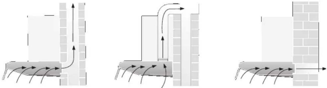
The exhaust air is discharged upwards through a ventilation shaft or directly through the outside wall into the open.
Exhaust air must not be discharged via a smoke or exhaust gas flue which is already in use or via a shaft which is used for ventilating rooms in which fireplaces are located.
Discharge exhaust air in accordance with official and statutory regulations (e.g. national building regulations).
Discharge of air into smoke or exhaust air flues which are not in use requires the consent of a heating engineer.
If the extractor hood is operated in exhaust-air mode at the same time as a flue-type heater (e.g. gas, oil or solid-fuel heater, instantaneous water heater, boiler), ensure that there is an adequate air supply which the heater requires for combustion.
Safe operation is possible provided that the partial vacuum in the room in which the heater is installed does not exceed 4 Pa (0.04 mbar).
This can be achieved if the combustion air is able to flow through non-lockable openings, e.g. in doors, windows and in conjunction with an air supply/air-intake wall box or by other technical procedures such as reciprocal interlocking.
This can be achieved if the combustion air is able to flow through non-lockable openings, e.g. in doors, windows and in conjunction with an air supply/air-intake wall box or by other technical procedures such as reciprocal interlocking.
If the air intake is inadequate, there is a risk of poisoning from combustion gases which are drawn back into the room.
An air-intake/exhaust-air wall box by itself is no guarantee that the limiting value will not be exceeded.
Note: When assessing the overall requirement, the combined ventilation system for the entire household must be taken into consideration. This rule does not apply to the use of cooking appliances, such as hobs and gas cookers.
The extractor hood can be used without restriction in circulating air mode – with an activated carbon filter.
An extractor hood which is operated in exhaust-air mode should be fitted with a one-way flap if there is no one-way flap in the exhaust-air pipe or wall box. If a one-way flap is not supplied with the appliance, you can purchase one from your dealer (see optional accessories in the Instructions for use).
⚠ Do NOT cut out the inner part of the exhaust-air connection.
Fitting the one-way flap:
☐ Insert the two lugs on the one-way flap into the holes in the exhaust-air connection.
If the exhaust air is conveyed through the exterior wall, a telescopic wall box should be used.
natural_image
Diagram of a mechanical component with arrows indicating motion or force direction (no text or symbols)Optimum performance of the extractor hood:
□ Short, smooth exhaust-air pipe.
☐ Minimum number of pipe bends.
☐ Largest possible pipe diameter (120 mm dia. recommended) and large pipe bends.
If long, rough exhaust-air pipes, many pipe bends or smaller pipe diameters are used, the air extraction rate will no longer be at an optimum level and there will be an increase in noise.
☐ Round pipes:
Short discharge pipe: Inner diameter at least 100 mm, extended discharge pipe: Inner diameter at least 120 mm.
☐ Flat ducts must have an inner cross-section equivalent to round pipes with an inner diameter of 100/120 mm. There should be no sharp bends.
100 m dia approx. 78 cm ^2 125 m dia approx. 113 cm ^2
□ If pipe diameters differ:
Insert sealing strip.
☐ Ensure an adequate air supply for exhaust-air mode.
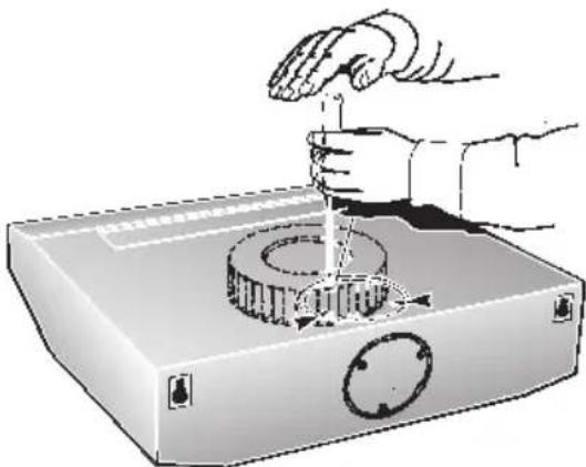
Exhaust air upwards:
Pipe diameter: 100 or 120 mm
☐ Break off cover on the top of the extractor hood; strike the retaining points with a tool.
natural_image
Illustration of a hand using a tool to press or install a mechanical component, no text or symbols present⚠️ Toprevent damage to the fan, hold the tool vertically.
☐ Remove the broken off metal part (possibly a noisy and disruptive procedure).
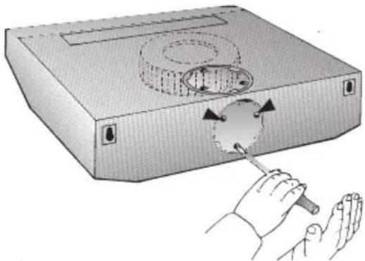
☐ If the pipe diameter is 120 mm, cut out the inner part of the exhaust-air connection.
natural_image
Illustration of hands using a tool to cut a circular object with a textured surface (no text or symbols)☐ Insert the exhaust-air connection and turn as far as possible.
Before installation
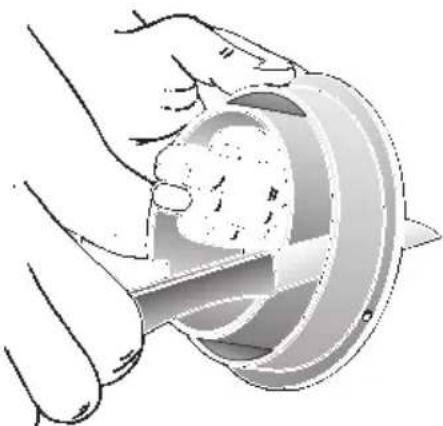
Exhaust air towards the rear:
Pipe diameter: 100 mm
☐ Break off cover on the rear panel of the extractor hood; strike the retaining points with a tool.
natural_image
Illustration of a hand using a tool to press or install a circular component on a rectangular device (no text or symbols visible)⚠️ Toprevent damage to the fan, hold the tool vertically.
☐ Remove the broken off metal part (possibly a noisy and disruptive procedure).
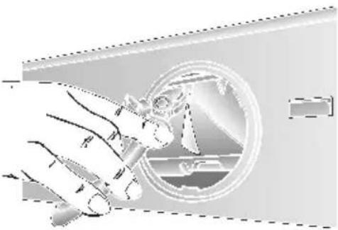
☐ If the extractor hood has 2 motors, the opening on the plastic part must be made at the rear; cut through the 3 ribs and remove the cut-off part.
natural_image
Illustration of a hand holding a small object, with a circular inset showing a ship and a window (no text or symbols)☐ Cut off the outer part of the exhaust-air connection.

natural_image
Illustration of a hand holding a circular object with a tool, no text or symbols present☐ Insert the inner part and turn as far as possible.
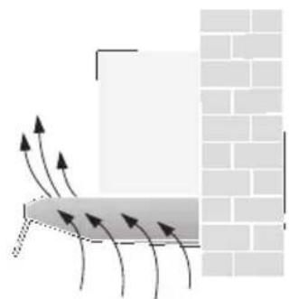
Circulating-air mode
natural_image
Diagram showing airflow or heat transfer between a rectangular block and a brick wall, with arrows indicating direction (no text or symbols)☐ With activated carbon filter if exhaust-air mode is not possible.
☐ The air purified by an additional activated carbon filter is conveyed back into the room.
☐ For insertion of the activated carbon filter see Instructions for use.
☐ If the extractor hood is switched from exhaust-air mode to circulating-air mode, the exhaust-air opening must be sealed to prevent a hazardous situation (see optional accessories in the Instructions for use).
Electrical connection
WARNING: THIS APPLIANCE MUST BE EARTHED
IMPORTANT: Fitting a Different Plug:
The wires in the power cord are colour-coded as follows:
Green and Yellow – Earth
Blue - Neutral
Brown - Live
If you fit your own plug, the colours of these wires may not correspond with the identifying marks on the plug terminals.
Proceed as follows:
- Connect the green and yellow (Earth) wire to the terminal in the plug marked 'E' or with the symbol (≡), or coloured green or green and yellow.
- Connect the blue (Neutral) wire to the terminal in the plug marked 'N' or coloured black.
Electrical connection
- Connect the brown (Live) wire to the terminal marked 'L', or coloured red.
The extractor hood may be connected to a correctly installed earthed socket only. Attach the earthed socket near the extractor hood in an accessible position.
☐ The earthed socket should be connected via its own power circuit.
⚠️ If appliances do not feature the OFF delay function, the indicator may start flashing when the extractor hood has been switched off for several hours via a separate switch, even though the grease filters are not yet saturated.
(See instructions for use, section on filter and maintenance).
Electrical specifications:
These can be found on the rating plate inside the appliance following removal of the filter frames.
⚠️ Before carrying out repairs, always isolate the appliance.
Length of the connection cable: 1.30 m. If permanent connection is required:
The extractor hood may only be connected by an electrician registered with the local electricity board.
A disconnecting device must be provided on the installation side. Switches with a contact opening of more than 3 mm and all-pole disconnection are regarded as disconnecting devices. These include LS switches and contactors.
This extractor hood complies with EU regulations on interference suppression.
Fitting the extractor hood
To the wall
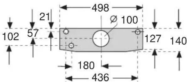
50 cm wide extractor hood: With 3 screws.
text_image
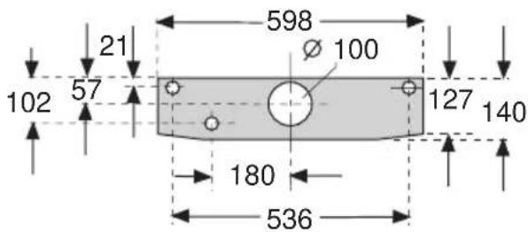
21 498 100 102 57 127 140 180 436Fitting the extractor hood
60 cm wide extractor hood: With 3 screws.
text_image
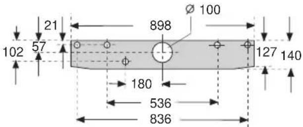
21 598 100 102 57 127 140 180 53690 cm wide extractor hood: With 5 screws.
text_image
21 102 57 898 Ø 100 127 140 180 536 836- Mark mounting boreholes. Dimensions can be found in or use template.
- Drill 8 mm dia. holes and insert wall plugs flush with the wall.
- Screw in the upper screws (on left and right) until there is a gap of approx. 7 mm between the screw head and the wall.
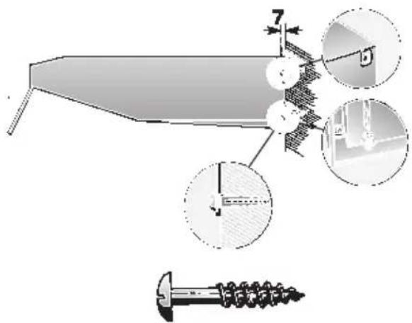
text_image
Technical diagram showing a mechanical assembly with labeled components and magnified views of detail- Remove the filter grille (see Instructions for use)
- Attach the extractor hood.
- Tighten the lower screw (with washer) inside the extractor hood.
Fitting the extractor hood
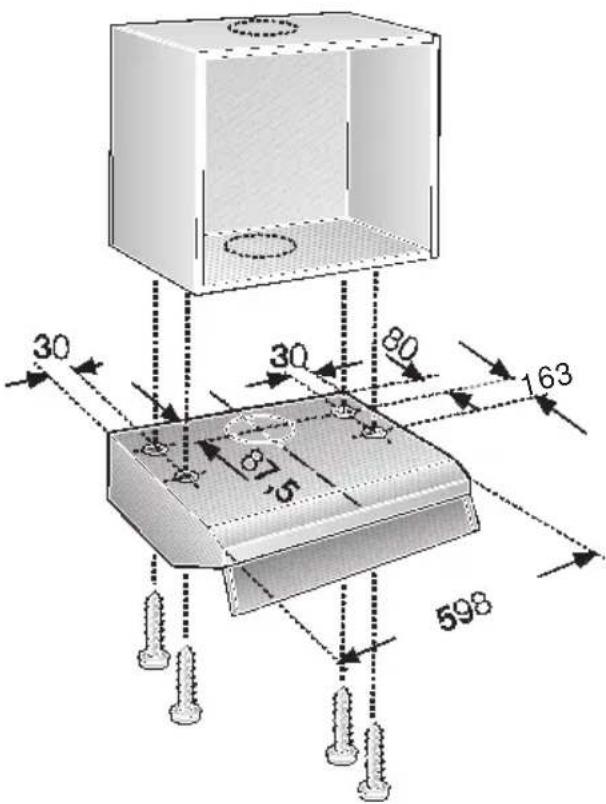
To a wall-hanging cupboard
50 cm wide extractor hood: With 4 screws.
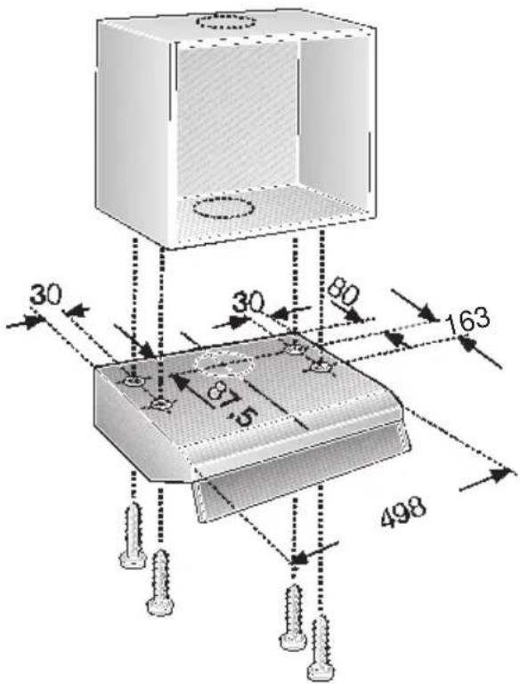
text_image
30 30 80 163 49860 cm wide extractor hood: With 4 screws.
text_image
30 30 80 163 5 59890 cm wide extractor hood: With 6 screws.
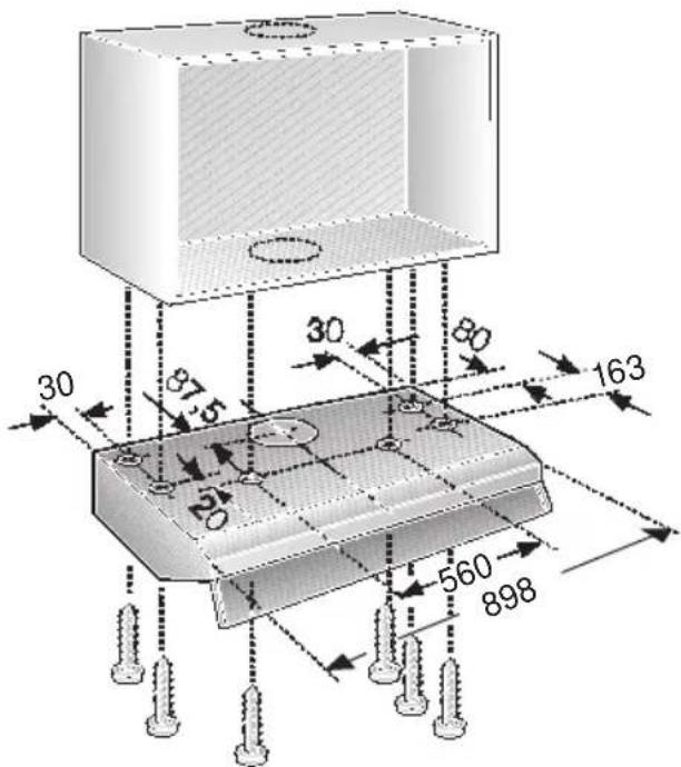
text_image
30 87 5 20 30 80 163 560 898-
Dimensions for the mounting boreholes can be found in, or place a template on the base of the wall-hanging cupboard.
-
Mark the mounting holes and make pilot holes with a bradawl. In exhaust-air mode (upwards) mark the exhaust-air opening and saw out.
☐ Consider the location of the connection cable; if required, saw out the cupboard.
-
Remove the filter grille (see Instructions for use).
-
Screw the extractor hood to the base of the cupboard.
Final assembly
Exhaust-air mode:
☐ Stick the enclosed covering foil over the air outlet grille on the top of the extractor hood. Ensure that the surface is clean.
natural_image
Illustration of a kitchen air conditioner unit with ventilation grilles and a handle (no text or symbols)□ Connect the pipes.
2-motor extractor hood Selecting the operating mode:
- Exhaust-air mode: Position 1 - Circulating-air mode: Position 2 - Select the operating mode on the left or right with a screwdriver.
text_image
1 2 2 1 2 1- Connect to the power supply. - Insert the filter grille (see Instructions for use).
Weight in kg:
| Exhaust airWidth | With circulating air | |
| 50 cm | 7,0 | 8,0 |
| 60 cm1 motor | 8,0 | 9,0 |
| 60 cm2 motors | 10,0 | 11,0 |
| 90 cm | 13,0 14,0 |
Design changes with respect to technical development shall remain withheld.
Mode d'emploi:
natural_image
3D technical diagram of a mechanical component with grid pattern and mounting holes (no text or symbols)Eclairage
Grille du filtre
text_image
Diagram showing numbered items with icons and symbols, likely illustrating a sequence or process with visual indicators.0
natural_image
Diagram of a perforated metal structure with circular arrows indicating flow or movement, showing internal mesh patterns and structural details (no text or symbols present)natural_image
Diagram of a mechanical device with internal components and an arrow indicating direction (no text or symbols)natural_image
Illustration of a hand holding a tool or tool, with no visible text or symbolsnatural_image
Isometric view of a grid-patterned surface with no text or symbolstext_image
Diagram illustrating a mechanical assembly or cleaning process with labeled components and directional arrows indicating movement or assembly.natural_image
Diagram of a roof structure with heat exchanger and directional arrows indicating airflow or movement (no text or symbols)natural_image
Illustration of a hand inserting a bulb into a cylindrical device (no text or symbols visible)natural_image
Diagram of a mechanical component with arrows indicating motion or force direction (no text or symbols)natural_image
Illustration of a hand using a tool to press or install a mechanical component, no text or symbols presentnatural_image
Illustration of hands using a tool to cut a circular object into a mechanical component (no text or symbols visible)natural_image
Illustration of hands using a tool to adjust or install a component on a device (no text or symbols visible)natural_image
Illustration of a hand holding a pen, with a circular diagram showing a mechanical component inside (no text or symbols)natural_image
Illustration of a hand holding a small object through a cylindrical container (no text or symbols visible)natural_image
Diagram showing airflow or heat transfer between a rectangular block and a brick wall, with arrows indicating direction (no text or symbols)text_image
Technical diagram showing mechanical assembly with labeled components and magnified views of detailnatural_image
Illustration of a kitchen air conditioner unit with ventilation grilles and a handle (no text or symbols)natural_image
Diagram of a perforated metal structure with circular arrows indicating flow or movement, showing internal mesh patterns and structural details (no text or symbols)natural_image
Diagram of a mechanical device with internal components and an arrow indicating direction (no text or symbols)natural_image
Illustration of a hand holding a tool or tool near a window (no text or symbols visible)natural_image
Isometric view of a grid-patterned surface with three white rectangular cutouts (no text or symbols)Koolstofffilter:
text_image
Diagram illustrating a mechanical assembly with labeled components and magnified views of the main component.natural_image
Diagram of a refrigerator interior with internal compartments and directional arrows indicating movement (no text or symbols)natural_image
Illustration of a robotic arm interacting with a mechanical component (no text or symbols visible)natural_image
Diagram of a mechanical device with a circular housing and internal components, showing no text or symbols.natural_image
Illustration of a hand using a tool to press or install a circular component on a base (no text or symbols present)natural_image
Illustration of hands using a tool to cut a circular object with a handle (no text or symbols visible)natural_image
Illustration of hands using a screwdriver to adjust a circular component on a device (no text or symbols present)natural_image
Illustration of a hand holding a pen, with a circular diagram showing mechanical components inside (no text or symbols)natural_image
Illustration of a hand holding a circular object with a tool, no text or symbols presentnatural_image
Diagram showing airflow or heat transfer between a wall and brick wall, with arrows indicating direction (no text or symbols)text_image
Technical diagram showing a mechanical assembly with labeled components and magnified views of detailnatural_image
Illustration of a kitchen air conditioner unit with ventilation grilles and a handle (no text or symbols)natural_image
3D technical diagram of a mechanical component with hexagonal lattice structure (no text or symbols)text_image
Diagram showing numbered items with icons and symbols, likely illustrating a sequence or process with visual indicators.natural_image
Diagram of a perforated metal structure with circular arrows indicating flow or movement, showing internal mesh patterns and structural details (no text or symbols)natural_image
Diagram of a 3D printer or scanner with internal components and an arrow indicating orientation (no text or symbols)natural_image
Illustration of a hand holding a tool or tool near a window (no text or symbols visible)natural_image
Isometric diagram of a folded panel or circuit board with internal components (no text or symbols)text_image
Diagram illustrating a mechanical assembly or mounting process with labeled components and directional arrows, including magnified views of the main component.natural_image
Diagram of a refrigerated storage unit with internal cooling system and directional arrows indicating rotation (no text or symbols)natural_image
Illustration of a robotic arm interacting with a mechanical component (no text or symbols visible)natural_image
Diagram of a mechanical device with internal components and directional arrows indicating motion (no text or symbols)natural_image
Illustration of a hand using a tool to press or install a mechanical component, no text or symbols presentnatural_image
Illustration of a hand holding a circular object with a ruler inside, no text or symbols presentnatural_image
Illustration of hands using a tool to adjust or install a mechanical component, no text or symbols presentnatural_image
Illustration of a hand inserting a small mechanical component into a circular housing (no text or symbols)natural_image
Illustration of a hand holding a small object through a cylindrical container (no text or symbols visible)natural_image
Diagram showing airflow or heat transfer between a chair and brick wall (no text or symbols)text_image
Technical diagram showing a mechanical assembly with labeled components and cross-sectional viewsnatural_image
Illustration of a kitchen air conditioner unit with ventilation slots and a handle (no text or symbols)□ Collegare i tubi.
| ScaricoLarghezza Ricircolo | ||
| 50 cm | 7,0 | 8,0 |
| 60 cm1 motore | 8,0 | 9,0 |
| 60 cm2 motori | 10,0 | 11,0 |
| 90 cm | 13,0 14,0 | |
natural_image
3D technical diagram of a mechanical component with grid pattern and mounting holes (no text or symbols)natural_image
Diagram of a perforated metal structure with circular arrows indicating flow or movement, showing internal mesh patterns and structural details (no text or symbols present)natural_image
Diagram of a mechanical device with internal components and an arrow indicating direction (no text or symbols)natural_image
Illustration of a hand holding a tool or tool near a window (no text or symbols visible)natural_image
Isometric view of a folded paper or sheet with two white cutouts, no text or symbols present.text_image
Diagram showing mechanical assembly with labeled components and magnified views of a devicenatural_image
Diagram of a refrigerated refrigerator interior with internal cooling system and directional arrows indicating airflow (no text or symbols)natural_image
Illustration of a robotic arm interacting with a mechanical component (no text or symbols visible)natural_image
Diagram of a mechanical assembly with arrows indicating motion or force direction (no text or symbols)natural_image
Illustration of a hand using a tool to press or install a circular component on a base (no text or symbols visible)natural_image
Illustration of a hand using a tool to cut a circular object into a mechanical component (no text or symbols visible)natural_image
Illustration of a hand holding a screwdriver next to a device with a circular component and arrow indicating rotation (no text or symbols)natural_image
Illustration of a hand holding a pen, with a circular diagram showing a mechanical component inside (no text or symbols)natural_image
Illustration of hands using a tool to cut a circular object (no text or symbols visible)natural_image
Diagram showing airflow or heat transfer between a rectangular block and a brick wall, with arrows indicating direction (no text or symbols)natural_image
Illustration of a kitchen air conditioner unit with ventilation grilles and a handle (no text or symbols)natural_image
Diagram of a perforated metal tray with circular arrows indicating flow or movement, showing internal structure and texture (no text or symbols)natural_image
Diagram of a mechanical device with two circular components and an open lid, showing internal structure and directional arrow (no text or symbols)- Retirar a grelha de arame e o filtro saturado.
natural_image
Illustration of a hand holding a document or scroll with a magnified view of the paper (no text or symbols visible)natural_image
Isometric view of a grid-patterned surface with three white rectangular cutouts (no text or symbols)natural_image
Diagram of a refrigerated storage unit with internal cooling system and directional arrows indicating rotation (no text or symbols)natural_image
Illustration of a robotic arm interacting with a mechanical component (no text or symbols visible)natural_image
Diagram of a mechanical device with a circular housing and internal components, showing motion arrows (no text or symbols)natural_image
Illustration of a hand using a tool to press or install a mechanical component, with no visible text or symbols.natural_image
Illustration of a hand holding a tool interacting with a circular object inside a mechanical component (no text or symbols visible)natural_image
Illustration of hands using a screwdriver to adjust a circular component on a rectangular device (no text or symbols)natural_image
Illustration of a hand holding a small mechanical component, with no visible text or symbolsnatural_image
Illustration of a hand holding a circular object with a tool, no text or symbols presentnatural_image
Diagram showing airflow or heat transfer between a rectangular object and a brick wall, with arrows indicating direction (no text or symbols)text_image
Technical diagram showing mechanical assembly with labeled components and cross-sectional viewsnatural_image
Illustration of a kitchen air conditioner unit with ventilation grilles and a handle (no text or symbols)| Largura | Exaustão de ar | Circulação de ar |
| 50 cm | 7,0 | 8,0 |
| 60 cm com 1 motor | 8,0 | 9,0 |
| 60 cm com 2 motores | 10,0 | 11,0 |
| 90 cm | 13,0 14,0 |
natural_image
3D technical diagram of a perforated metal bracket with circular holes, showing internal structure (no text or symbols)natural_image
Diagram of a perforated metal structure with circular arrows indicating flow or movement, showing internal grid patterns and no readable text or symbols.- Снимите решетку.
natural_image
Diagram of a mechanical device with two circular components and an arrow indicating direction (no text or symbols)natural_image
Illustration of a hand holding a document or scroll with a magnified view (no text or symbols visible)natural_image
Isometric diagram of a grid-patterned panel with four cutouts (no text or symbols)text_image
Diagram illustrating a mechanical assembly or assembly process with labeled components and directional arrows indicating movement or flow.natural_image
Diagram of a refrigerated or insulated room interior with heat exchanger and directional arrows indicating airflow or movement (no text or symbols present)natural_image
Illustration of a robotic arm interacting with a mechanical component (no text or symbols visible)natural_image
Diagram showing fluid flow around a rectangular object with arrows indicating direction (no text or symbols)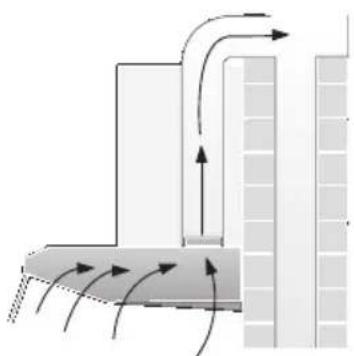
natural_image
Diagram showing airflow or heat transfer between two building walls with directional arrows (no text or symbols)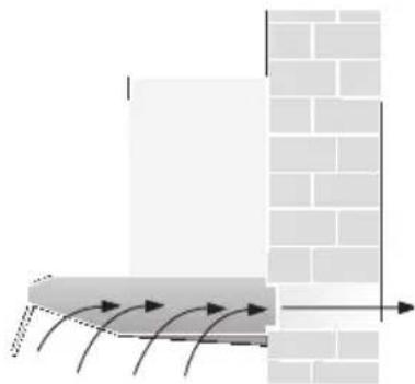
natural_image
Diagram showing airflow or heat transfer between a rectangular block and a brick wall, with no visible text or symbols.natural_image
Diagram of a mechanical component with internal structure and directional arrows indicating motion (no text or symbols)natural_image
Illustration of a hand using a tool to press or install a circular component on a base (no text or symbols visible)natural_image
Illustration of hands using a tool to cut a circular object, no text or symbols presentnatural_image
Illustration of a hand using a screwdriver to clean or inspect a circular component on a rectangular device (no text or symbols)natural_image
Illustration of a hand holding a pen, with a circular emblem and mechanical components inside (no text or symbols)natural_image
Illustration of a hand holding a small object inside a cylindrical container (no text or symbols visible)natural_image
Diagram showing airflow or heat transfer between a rectangular object and a brick wall, with arrows indicating direction (no text or symbols)text_image
Technical diagram showing screw fastening process with magnified views of mechanical components and detail viewnatural_image
Illustration of a kitchen air conditioner unit with ventilation grilles and a handle (no text or symbols)natural_image
3D technical diagram of a meshed metal grate or drain structure with circular holes and dashed lines indicating hidden edges (no text or symbols)Aydınlatma
Filtre izgarası
İşletme türleri
Hava çıkış modu:
natural_image
Diagram of a perforated metal structure with circular arrows indicating flow or movement, no text or symbols present.natural_image
Diagram of a mechanical device with internal components and an arrow indicating direction (no text or symbols)natural_image
Illustration of a hand holding a document or scroll, with no visible text or symbolsnatural_image
Isometric view of a grid-patterned panel with four white arrows indicating directional flow (no text or symbols)Aktif karbon filtresi:
natural_image
Diagram of a refrigerated storage unit with internal cooling system and directional arrows indicating flow (no text or symbols)natural_image
Illustration of a robotic arm interacting with a mechanical component (no text or symbols visible)natural_image
Diagram of a mechanical component with internal structure and directional arrows indicating movement (no text or symbols)natural_image
Illustration of a hand using a tool to press or install a mechanical component, no text or symbols presentnatural_image
Illustration of hands holding a circular object with a ruler, no text or symbols presentnatural_image
Illustration of hands using a tool to adjust or install a mechanical component with a circular component (no text or symbols present)natural_image
Illustration of a hand holding a pen, with a circular inset showing mechanical components (no text or symbols)natural_image
Illustration of a hand holding a small object through a cylindrical container (no text or symbols visible)natural_image
Diagram showing airflow or heat transfer between a rectangular structure and a brick wall (no text or symbols)text_image
Technical diagram showing a mechanical assembly with labeled components and magnified views of detailnatural_image
Illustration of a kitchen fan with ventilation grilles and a handle (no text or symbols)| Atık hava | Dolksimli hava | |
| 50 cm | 7,0 | 8,0 |
| 60 cm1 motorlu | 8,0 | 9,0 |
| 60 cm2 motorlu | 10,0 | 11,0 |
| 90 cm | 13,0 14,0 |