H61MVITX - Motherboard ASROCK - Free user manual and instructions
Find the device manual for free H61MVITX ASROCK in PDF.


User questions about H61MVITX ASROCK
0 question about this device. Answer the ones you know or ask your own.
Ask a new question about this device
Download the instructions for your Motherboard in PDF format for free! Find your manual H61MVITX - ASROCK and take your electronic device back in hand. On this page are published all the documents necessary for the use of your device. H61MVITX by ASROCK.
USER MANUAL H61MVITX ASROCK
No part of this installation guide may be reproduced, transcribed, transmitted, or translated in any language, in any form or by any means, except duplication of documentation by the purchaser for backup purpose, without written consent of ASRock Inc.
Products and corporate names appearing in this guide may or may not be registered trademarks or copyrights of their respective companies, and are used only for identification or explanation and to the owners' benefit, without intent to infringe.
Disclaimer:
Specifications and information contained in this guide are furnished for informational use only and subject to change without notice, and should not be constructed as a commitment by ASRock. ASRock assumes no responsibility for any errors or omissions that may appear in this guide.
With respect to the contents of this guide, ASRock does not provide warranty of any kind, either expressed or implied, including but not limited to the implied warranties or conditions of merchantability or fitness for a particular purpose. In no event shall ASRock, its directors, officers, employees, or agents be liable for any indirect, special, incidental, or consequential damages (including damages for loss of profits, loss of business, loss of data, interruption of business and the like), even if ASRock has been advised of the possibility of such damages arising from any defect or error in the guide or product.

This device complies with Part 15 of the FCC Rules. Operation is subject to the following two conditions:
(1) this device may not cause harmful interference, and
(2) this device must accept any interference received, including interference that may cause undesired operation.
CALIFORNIA, USA ONLY
The Lithium battery adopted on this motherboard contains Perchlorate, a toxic substance controlled in Perchlorate Best Management Practices (BMP) regulations passed by the California Legislature. When you discard the Lithium battery in California, USA, please follow the related regulations in advance.
"Perchlorate Material-special handling may apply, see www.dtsc.ca.gov/hazardouswaste/perchlorate"
The terms HDMITM and HDMI High-Definition Multimedia Interface, and the HDMI logo are trademarks or registered trademarks of HDMI Licensing LLC in the United States and other countries.

HIGHDEFINITION MULTIMEDIA INTERFACE
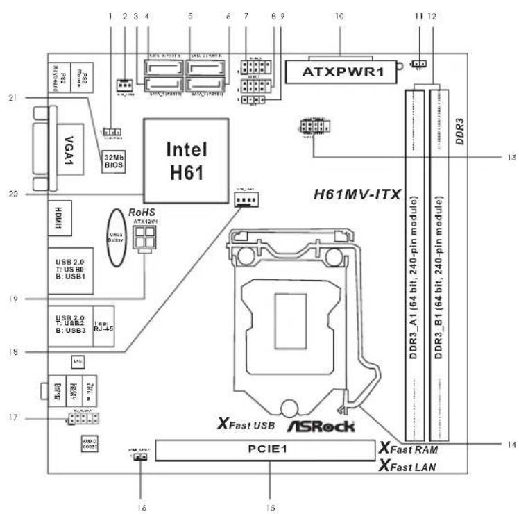
Motherboard Layout
1 Clear CMOS Jumper (CLRCMOS1) 12 2 x 240-pin DDR3 DIMM Slots
2 Chassis Fan Connector (CHA_FAN1) (Dual Channel: DDR3_A1, DDR3_B1)
3 SATA2 Connector (SATA_1(PORT 1)) 13 System Panel Header (PANEL1)
4 SATA2 Connector (SATA_0 (PORT 0)) 14 1155-Pin CPU Socket
5 SATA2 Connector (SATA_2(PORT 4)) 15 PCI Express 3.0 x16 Slot (PCIE1)
6 SATA2 Connector (SATA_3 (PORT 5)) 16 HDMI_SPDIF Header (HDMI_SPDIF1)
7 USB 2.0 Header (USB4_5) 17 Front Panel Audio Header (HD_AUDIO1)
8 USB 2.0 Header (USB6_7) 18 CPU Fan Connector (CPU_FAN1)
9 Consumer Infrared Module Header (CIR1) 19 ATX 12V Power Connector (ATX12V1)
10ATX 12V Power Connector (ATX12V1) 20 Intel H61 Chipset
11 Chassis Intrusion Header (CI1) 21 32Mb SPI Flash
I/O Panel

1 PS/2 Mouse Port (Green) 6 USB 2.0 Ports (USB23)
*2 LAN RJ-45 Port 7 USB 2.0 Ports (USB01)
3 Line In (Light Blue) 8 HDMI Port
**4 Front Speaker (Lime) 9 D-Sub Port
5 Microphone (Pink) 10 PS/2 Keyboard Port (Purple)
- There are two LED next to the LAN port. Please refer to the table below for the LAN port LED indications.
LAN Port LED Indications
Activity/Link LED
SPEEDLED
ACT/LINK SPEED
| Status | Description | Status | Description |
| Off | No Link | Off | 10Mbps connection |
| Blinking | Data Activity | Orange | 100Mbps connection |
| On | Link Green | 1Gbps connection | |
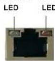
LAN Port
** To enable Multi-Streaming function, you need to connect a front panel audio cable to the front panel audio header. Please refer to below steps for the software setting of Multi-Streaming. For Windows XP:
After restarting your computer, you will find "Mixer" tool on your system. Please select "Mixer ToolBox", click "Enable playback multi-streaming", and click "ok". Choose "2CH" or

"4CH" and then you are allowed to select "Realtek HDA Primary output" to use Rear Speaker and Front Speaker, or select "Realtek HDA Audio 2nd output" to use front panel audio. Then reboot your system.
For Windows® 8 / 7 / Vista™
After restarting your computer, please double-click "Realtek HD Audio Manager" on the system tray. Set "Speaker Configuration" to "Quadraphonic" or "Stereo". Click "Device advanced settings", choose "Make front and rear output devices playbacks two different audio streams simultaneously", and click "ok". Then reboot your system.
1. Introduction
Thank you for purchasing ASRock H61MV-ITX motherboard, a reliable motherboard produced under ASRock's consistently stringent quality control. It delivers excellent performance with robust design conforming to ASRock's commitment to quality and endurance.
This Quick Installation Guide contains introduction of the motherboard and step-by-step installation guide. More detailed information of the motherboard can be found in the user manual presented in the Support CD.

Because the motherboard specifications and the BIOS software might be updated, the content of this manual will be subject to change without notice. In case any modifications of this manual occur, the updated version will be available on ASRock website without further notice. You may find the latest VGA cards and CPU support lists on ASRock website as well. ASRock website http://www.asrock.com If you require technical support related to this motherboard, please visit our website for specific information about the model you are using. www.asrock.com/support/index.asp
1.1 Package Contents
ASRock H61MV-ITX Motherboard (Mini-ITX Form Factor)
ASRock H61MV-ITX Quick Installation Guide
ASRock H61MV-ITX Support CD
2 x Serial ATA (SATA) Data Cables (Optional)
1 x I/O Panel Shield

ASRock Reminds You...
To get better performance in Windows® 8 / 8 64-bit / 7 / 7 64-bit / Vista™ / Vista™ 64-bit, it is recommended to set the BIOS option in Storage Configuration to AHCI mode. For the BIOS setup, please refer to the "User Manual" in our support CD for details.
1.2 Specifications
| Platform - Mini-ITX - All Solid Capacitor | Form Factor design |
| CPU - Supports 3 LGA1155 Package | rd and 2nd Generation Intel® Core™ i7 / i5 / i3 in Turbo Boost 2.0 Technology unlocked CPU |
| Supports Intel - Supports K-Series | |
| Chipset - Intel - Supports Intel | ® H61 ® Rapid Start Technology and Smart Connect Technology |
| Memory - Dual Channel DDR3 Memory Technology - 2 x DDR3 DIMM slots - Supports DDR3 1600/1333/1066 non-ECC, un-buffered memory (DDR3 1600 with Intel® Ivy Bridge CPU, DDR3 1333 with Intel® Sandy Bridge CPU) - Max. capacity of system memory: 16GB (see CAUTION 1) - Supports Intel Intel | ® Extreme Memory Profi le (XMP) 1.3 / 1.2 with® Ivy Bridge CPU |
| Expansion Slot - 1 * PCIE 3.0 is only supported with Intel | × PCI Express 3.0 x16 slot (PCIE1 @ x16 mode) * Ivy Bridge CPU. With® Sandy Bridge CPU, it only supports PCIE 2.0. |
| Graphics be supported only integrated. - Supports Intel Sync Video 2.0, Intel Technology, Intel with Intel | *® HD Graphics Built-in Visuals and the VGA outputs can with processors which are GPU ® HD Graphics Built-in Visuals: Intel® Quick ® InTru™ 3D, Intel® Clear Video HD ® Insider™, Intel® HD Graphics 2500/4000 ® Ivy Bridge CPU |
| - Supports Intel Sync Video, Intel Technology, Intel Vector Extensions | ® HD Graphics Built-in Visuals: Intel® Quick ® InTru™ 3D, Intel® Clear Video HD ® HD Graphics 2000/3000, Intel® Advanced (AVX) with Intel ® Sandy Bridge CPU |
| - Pixel Shader 5.0, DirectX 11 with Intel Pixel Shader 4.1, DirectX 10.1 with Intel CPU. - Max. shared memory 1760MB with Intel Max. shared memory 1759MB with Intel CPU. - Dual VGA Output: support HDMI and D-Sub ports by independent display controllers | ® Ivy Bridge CPU. ® Sandy Bridge ® Ivy Bridge CPU. ® Sandy Bridge |
| - Supports HDMI 1.4a Technology with max. resolution up to 1920x1200 @ 60Hz - Supports D-Sub with max. resolution up to 2048x1536 @ 75Hz - Supports Auto Lio Sync, xvYCC and HBR (High Bit Rate Audio) with HDMI (Compliant HDMI monitor is required) (see CAUTION 2) - Supports HDCP function with HDMI port - Supports Full HD with HDMI port | Audio - 5.1 CH HD Audio (Realtek ALC662 Audio Codec) |
| LAN - PCIE x1 Gigabit LAN 10/100/1000 Mb/s - Realtek RTL8111E - Supports Wake-On-LAN - Supports LAN Cable Detection - Supports Energy Effi client Ethernet 802.3az - Supports PXE | Rear Panel I/O I/O Panel - 1 x PS/2 Mouse Port - 1 x PS/2 Keyboard Port - 1 x D-Sub Port - 1 x HDMI Port - 4 x Ready-to-Use USB 2.0 Ports - 1 x RJ-45 LAN Port with LED (ACT/LINK LED and SPEED LED) - HD Audio Jack: Line in / Front Speaker / Microphone |
| Connector - 4 x SATA2 3.0 Gb/s connectors, support NCQ, AHCI and Hot Plug functions - 1 x CIR header - 1 x HDMI_SPDIF header - 1 x Chassis Intrusion header - 1 x CPU Fan connectors (4-pin) - 1 x Chassis Fan connector (3-pin) - 24 pin ATX power connector - 4 pin 12V power connector - Front panel audio connector - 2 x USB 2.0 headers (support 4 USB 2.0 ports) | BIOS Feature - 32Mb AMI UEFI Legal BIOS with GUI support - Supports "Plug and Play" - ACPI 1.1 Compliance Wake Up Events - Supports jumperfree |
| - SMBIOS 2.3.1 Support | |
| Support CD - Drivers, Utilities, AntiVirus Software (Trial Version), CyberLink MediaEpresso 6.5 Trial, Google Chrome Browser and Toolbar | |
| Hardware - CPU Temperature SensingMonitor - Chassis Temperature SensingCPU Fan TachometerChassis Fan TachometerCPU Quiet Fan (Allow Chassis Fan Speed Auto-Adjust by CPU Temperature)- CPU Fan Multi-Speed Control-CASE OPEN detection-Voltage Monitoring: +12V, +5V, +3.3V, CPU Vcore | |
| OS Vista | -Window\Goto\4-bit/7/7 64-bit/VistaTM/64-bit/XP/XP 64-bit compliant |
| Certifi cations - FCC, CE, WHQL-ErP/EuP Ready (ErP/EuP ready power supply is required) | |
- For detailed product information, please visit our website: http://www.asrock.com
WARNING
Please realize that there is a certain risk involved with overclocking, including adjusting the setting in the BIOS, applying Untied Overclocking Technology, or using third-party overclocking tools. Overclocking may affect your system's stability, or even cause damage to the components and devices of your system. It should be done at your own risk and expense. We are not responsible for possible damage caused by overclocking.
CAUTION!
- Due to the operating system limitation, the actual memory size may be less than 4GB for the reservation for system usage under Windows® 8 / 7 / Vista™ / XP. For Windows® OS with 64-bit CPU, there is no such limitation. You can use ASRock XFast RAM to utilize the memory that Windows® cannot use.
- xvYCC is only supported under Windows® 8 64-bit / 8 / 7 64-bit / 7. HBR is supported under Windows® 8 64-bit / 8 / 7 64-bit / 7 / Vista™ 64-bit / Vista™.
1.3 Pin Header Easy Installation Guide
ASRock motherboard is equipped with pin headers with obvious colors which indicate you to recognize the crucial headers more easily. Please refer to below illustrations for the pin definition of onboard headers. If you want to have more information about the usage of these headers, please refer to "Jumper Setup" and "Onboard Headers and Connectors" for details.
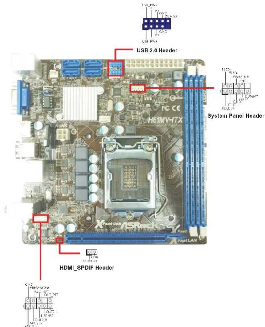
Front Panel Audio Header
usu3
1.4 Jumpers Setup
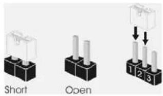
The illustration shows how jumpers are setup. When the jumper cap is placed on pins, the jumper is "Short". If no jumper cap is placed on pins, the jumper is "Open". The illustration shows a 3-pin jumper whose pin1 and pin2 are "Short" when jumper cap is placed on these 2 pins.
| Jumper | Setting | Description | |
| Clear CMOS Jumper | 1_2 | 2_3 | |
| (CLRCMOS1) | |||
| (see p.2, No. 1) | Clear CMOSDefault | ||
Note: CLRCMOS1 allows you to clear the data in CMOS. To clear and reset the system parameters to default setup, please turn off the computer and unplug the power cord from the power supply. After waiting for 15 seconds, use a jumper cap to short pin2 and pin3 on CLRCMOS1 for 5 seconds. However, please do not clear the CMOS right after you update the BIOS. If you need to clear the CMOS when you just finish updating the BIOS, you must boot up the system first, and then shut it down before you do the clear-CMOS action. Please be noted that the password, date, time and user default profile will be cleared only if the CMOS battery is removed.

If you clear the CMOS, the case open may be detected. Please adjust the BIOS option "Clear Status" to clear the record of previous chassis intrusion status.
1.5 Onboard Headers and Connectors

Onboard headers and connectors are NOT jumpers. Do NOT place jumper caps over these headers and connectors. Placing jumper caps over the headers and connectors will cause permanent damage of the motherboard!
Serial ATA2 Connectors These four Serial ATA2
(SATA_0 (PORT 0): (SATA2) connectors support SATA_0 (PORT 0) SATA_2 (PORT 4)
see p.2.No.4) SATA data cables for internal (SATA_1 (PORT 1): storage devices. The current
see p.2, No.3) SATA2 interface allows up to SATA_1 (PORT 1) SATA_3 (PORT 5) (SATA_2 (PORT 4): 3.0 Gb/s data transfer rate.
see p.2, No. 5)
(SATA 3 (PORT 5):
see p.2, No. 6
Serial ATA (SATA) Either end of the SATA data
Data Cable cable can be connected to the
(Optionai) SATA / SATA2 hard disk or the SATA2 connector on this
motherboard.
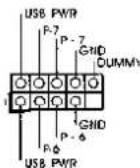
USB 2.0 Headers Besides four default USB 2.0
(9-pin USB4_5) ports on the I/O panel, there
(see p.2 No. 7) are two USB 2.0 headers on this motherboard. Each
USB 2.0 header can support
two USB 2.0 ports.
(9-pin USB6_7)
(see p.2 No.8)
Consumer Infrared Module Header This header can be used to
(4-pin CIR1)
(see p.2 No.9)
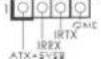
connect the remote
controller receiver.
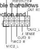
Front Panel Audio Header This is an interface for front
(9-pin HD AUDIO01) panel audio cable that allows
(see p.2 No.17) convenient connection and
control of audio devices.

-
High Definition Audio supports Jack Sensing, but the panel wire on the chassis must support HDA to function correctly. Please follow the instruction in our manual and chassis manual to install your system.
-
If you use AC'97 audio panel, please install it to the front panel audio header as below:
A. Connect Mic_IN (MIC) to MIC2_L.
B. Connect Audio_R (RIN) to OUT2_R and Audio_L (LIN) to OUT2_L.
C. Connect Ground (GND) to Ground (GND).
D. MIC_RET and OUT_RET are for HD audio panel only. You don't need to connect them for AC'97 audio panel.
E.To activate the front mic. For Windows XP/XP 64-bit OS:
Select "Mixer". Select "Recorder". Then click "FrontMic". For Windows 8/864-bit /7/764-bit/Vista™/Vista™64-bit OS: Go to the "FrontMic" Tab in the Realtek Control panel. Adjust "Recording Volume".
System Panel Header This header accommodates
(9-pin PANEL1) several system front
(see p.2 No.13)

functions.

Connect the power switch, reset switch and system status indicator on the chassis to this header according to the pin assignments below. Note the positive and negative pins before connecting the cables.
PWRBTN (Power Switch):
Connect to the power switch on the chassis front panel. You may configure the way to turn off your system using the power switch.
RESET (Reset Switch):
Connect to the reset switch on the chassis front panel. Press the reset switch to restart the computer if the computer freezes and fails to perform a normal restart.
PLED (System Power LED):
Connect to the power status indicator on the chassis front panel. The LED is on when the system is operating. The LED keeps blinking when the system is in S1 sleep state. The LED is off when the system is in S3/S4 sleep state or powered off (S5).
HDLED (Hard Drive Activity LED):
Connect to the hard drive activity LED on the chassis front panel. The LED is on when the hard drive is reading or writing data.
The front panel design may differ by chassis. A front panel module mainly consists of power switch, reset switch, power LED, hard drive activity LED, speaker and etc. When connecting your chassis front panel module to this header, make sure the wire assignments and the pin assignments are matched correctly.
Chassis Fan Connector Please connect the fan cables
(3-pin CHA_FAN1) to the fan connected
(see p.2 No. 2) match the black wire to the CHA FAH SPEEC
ground
pin.
CPU Fan Connectors Please connect the CPU fan
(4-pin CPU_FAN1) cable to the connector and
(see p.2 No. 18) match the black wire to the

ground
pin.

Though this motherboard provides 4-Pin CPU fan (Quiet Fan) support, the 3-Pin
CPU fan still can work successfully even without the fan speed control function. If you plan to connect the 3-Pin CPU fan to the CPU fan connector on this motherboard, please connect it to Pin 1-3.
Pin 1-3 Connected
3-Pin Fan Installation
ATX Power Connector Please connect an ATX power
(24-pin ATXPWR1) supply to this connector.
(see p.2 No.10)
12
1

Though this motherboard provides 24-pin ATX power connector, it can still work if you adopt a traditional 20-pin ATX power supply. To use the 20-pin ATX power supply, please plug your power supply along with Pin 1 and Pin 13.
20-Pin ATX Power Supply Installation
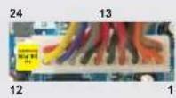
ATX 12V Power Connector Please connect an ATX 12V
(4-pin ATX12V1) power supply to this connector.
(see p.2 No.19)
HDMI_SPDIF Header HDMI_SPDIF header, providing
(2-pin HDMI_SPDIF1) SPDIF audio output to HDMI
(see p.2 No.16) VGA card, allows the system to
connect HDMI Digital TV/
projector/LCD devices. Please
connect the HDMI_SPDIF
connector of HDMI VGA card to
this
header.
Chassis Intrusion Header This motherboard supports
(2-pin C11) CASE OPEN detection feature
(see p.2, No. 11) that detects if the chassis cover
has been removed. This feature
requires a chassis with chassis
intrusion detection design.
2. BIOS Information
The Flash Memory on the motherboard stores BIOS Setup Utility. When you start up the computer, please press during the Power-On-Self-Test (POST) to enter BIOS Setup utility; otherwise, POST continues with its test routines. If you wish to enter BIOS Setup after POST, please restart the system by pressing
3. Software Support CD information
This motherboard supports various Microsoft® Windows® operating systems: 8 / 8 64-bit / 7 / 7 64-bit / Vista™ / Vista™ 64-bit / XP / XP 64-bit. The Support CD that came with the motherboard contains necessary drivers and useful utilities that will enhance motherboard features. To begin using the Support CD, insert the CD into your CD-ROM drive. It will display the Main Menu automatically if “AUTORUN” is enabled in your computer. If the Main Menu does not appear automatically, locate and double-click on the file “ASSETUP.EXE” from the BIN folder in the Support CD to display the menus.