PRT-6351 - Router Comtrend - Free user manual and instructions
Find the device manual for free PRT-6351 Comtrend in PDF.
| Product Type | Wireless ADSL/VDSL Router |
| Brand | Comtrend |
| Model | PRT-6351 |
| Dimensions (L x D x H) | Approximately 200 x 150 x 40 mm |
| Weight | Approximately 500 g |
| Power Supply | 12 V DC, 2.5 A (AC adapter included) |
| Ports | 1 RJ11 port (DSL), 4 RJ45 ports (LAN), 1 USB 3.0 port (900 mA output) |
| Main Functions | ADSL/VDSL routing, dual-band Wi-Fi (2.4 and 5 GHz), firewall, NAT, DHCP, VPN server |
| Wireless Standards | IEEE 802.11 a/b/g/n/ac (or ax depending on version) |
| Frequencies | 2.4 GHz, 5 GHz, 6 GHz (depending on version) |
| Maintenance and Cleaning | Disconnect before cleaning. Use a soft, dry cloth. Do not use abrasive products. |
| Safety | Do not open the casing. Do not use near water. Keep away from fire. Use in a well-ventilated area. |
| Spare Parts and Repairability | No user-replaceable parts. For repairs, consult a certified professional. |
| Operating Temperature | 0 °C to 40 °C |
| Operating Humidity | 10% to 90% (non-condensing) |
| Certifications | FCC Part 15, IC RSS-247, ICES-003, compliant with Canadian and US standards |
| Power Consumption | Max 30 W |
| Protection Rating | IP20 (indoor use only) |
| Package Contents | Router, AC adapter, DSL cable, Ethernet cable, Quick start guide |
Frequently Asked Questions - PRT-6351 Comtrend
User questions about PRT-6351 Comtrend
0 question about this device. Answer the ones you know or ask your own.
Ask a new question about this device
Download the instructions for your Router in PDF format for free! Find your manual PRT-6351 - Comtrend and take your electronic device back in hand. On this page are published all the documents necessary for the use of your device. PRT-6351 by Comtrend.
USER MANUAL PRT-6351 Comtrend
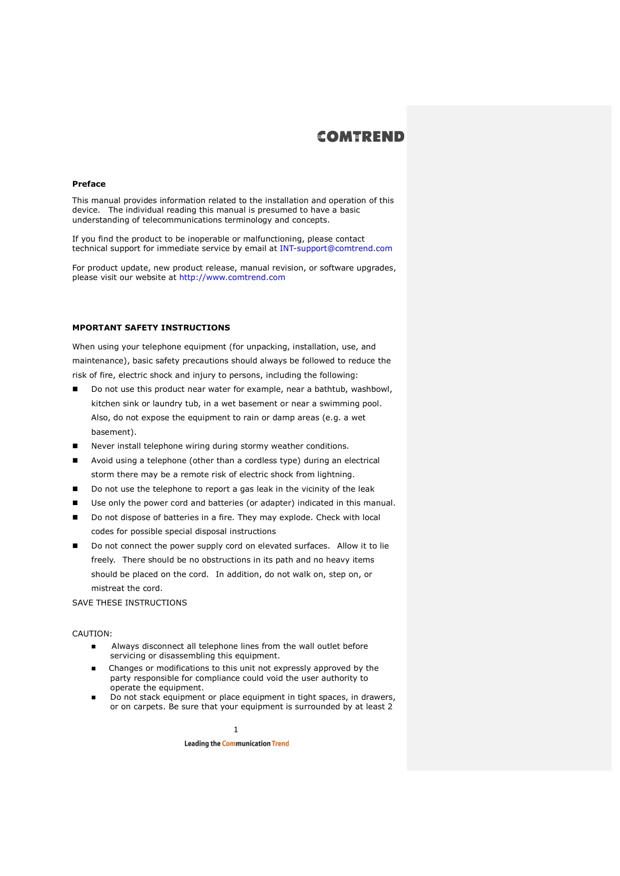
This manual provides information related to the installation and operation of this device. The individual reading this manual is presumed to have a basic understanding of telecommunications terminology and concepts.
If you find the product to be inoperable or malfunctioning, please contact technical support for immediate service by email at INT-support@comtrend.com
For product update, new product release, manual revision, or software upgrades, please visit our website at http://www.comtrend.com
IMPORTANT SAFETY INSTRUCTIONS
When using your telephone equipment (for unpacking, installation, use, and maintenance), basic safety precautions should always be followed to reduce the risk of fire, electric shock and injury to persons, including the following:
- Do not use this product near water for example, near a bathtub, washbowl, kitchen sink or laundry tub, in a wet basement or near a swimming pool. Also, do not expose the equipment to rain or damp areas (e.g. a wet basement).
- Never install telephone wiring during stormy weather conditions.
- Avoid using a telephone (other than a cordless type) during an electrical storm there may be a remote risk of electric shock from lightning.
Do not use the telephone to report a gas leak in the vicinity of the leak
Use only the power cord and batteries (or adapter) indicated in this manual. - Do not dispose of batteries in a fire. They may explode. Check with local codes for possible special disposal instructions
- Do not connect the power supply cord on elevated surfaces. Allow it to lie freely. There should be no obstructions in its path and no heavy items should be placed on the cord. In addition, do not walk on, step on, or mistreat the cord.
SAVE THESE INSTRUCTIONS
CAUTION:
Always disconnect all telephone lines from the wall outlet before servicing or disassembling this equipment.
Changes or modifications to this unit not expressly approved by the party responsible for compliance could void the user authority to operate the equipment.
- Do not stack equipment or place equipment in tight spaces, in drawers, or on carpets. Be sure that your equipment is surrounded by at least 2
COMTREND
inches of air space.
- To prevent interference with cordless phones, ensure that the gateway is at least 5 feet (1.5m) from the cordless phone base station.
If you experience trouble with this equipment, disconnect it from the network until the problem has been corrected or until you are sure that equipment is not malfunctioning.

WARNING
Any changes or modifications not expressly approved by the party responsible for compliance could void your authority to operate the equipment.
Note: This equipment has been tested and found to comply with the limits for a Class B digital device, pursuant to part 15 of the FCC Rules. These limits are designed to provide reasonable protection against harmful interference in a residential installation. This equipment generates, uses and can radiate radio frequency energy and, if not installed and used in accordance with the instructions, may cause harmful interference to radio communications. However, there is no guarantee that interference will not occur in a particular installation. If this equipment does cause harmful interference to radio or television reception, which can be determined by turning the equipment off and on, the user is encouraged to try to correct the interference by one or more of the following measures:
—Reorient or relocate the receiving antenna.
—Increase the separation between the equipment and receiver.
- Connect the equipment into an outlet on a circuit different from that to which the receiver is connected.
—Consult the dealer or an experienced radio/TV technician for help.
COMTREND
This device complies with Part 15 of the FCC Rules. Operation is subject to the following two conditions: (1) This device may not cause harmful interference, and (2) this device must accept any interference received, including interference that may cause undesired operation.
This Class B digital apparatus complies with Canadian ICES-003. To reduce potential radio interference to other users, the antenna type and its gain should be so chosen that the equivalent isotropically radiated power (e.i.r.p.) is not more than that permitted for successful communication. This device complies with Part 15 of the FCC Rules and Industry Canada licence-exempt RSS standard(s).
Operation is subject to the following two conditions:
- This device may not cause interference, and
- This device must accept any interference, including interference that may cause undesired operation of the device.
The operation of this device is prohibited on oil platforms, cars, trains, boats, and aircraft, except that operation of this device is permitted in large aircraft while flying above 10,000 feet. Operation of transmitters in the 5.925-7.125 GHz band is prohibited for control of or communications with unmanned aircraft systems.
- This Transmitter must not be co-located or operating in conjunction with any other antenna or transmitter.
- This equipment complies with FCC RF radiation exposure limits set forth for an uncontrolled environment. This equipment should be installed and operated with a minimum distance of 22cm between the radiator and your body.
ISED
This device complies with the ISED radiation exposure limit set forth for an uncontrolled environment. This device should be installed and operated with minimum distance 22cm between the radiator & your body. This transmitter must not be co-located or operating in conjunction with any other antenna or transmitter.
"This product meets the applicable Innovation, Science and Economic
COMTREND
development Canada technical specifications".
The device for operation in the band 5150-5250 MHz is only for indoor use to reduce the potential for harmful interference to co-channel mobile satellite systems.
This product meets the applicable Industry Canada technical specifications.
The Ringer Equivalence Number (REN) indicates the maximum number of devices allowed to be connected to a telephone interface. The termination of an interface may consist of any combination of devices subject only to the requirement that the sum of the RENs of all the devices not exceed five.
Operation shall be limited to indoor use only;
Operation on oil platforms, automobiles, trains, maritime vessels and aircraft shall be prohibited except for on large aircraft flying above 3,048m (10,000 ft). Devices shall not be used for control of or communications with unmanned aircraft systems.
Copyright©2023 Comtrend Corporation. All rights reserved. The information contained herein is proprietary to Comtrend Corporation. No part of this document may be translated, transcribed, reproduced, in any form, or by any means without prior written consent of Comtrend Corporation.
NOTE: This document is subject to change without notice.
Open Source Software Notice
Comtrend's products use open source software to fulfill their function.
Licenses for the open source software are granted under the GNU General Public License in various versions. For further information on the GNU General Public License see http://www.gnu.org/licenses/
You are allowed to modify all open source code (except for proprietary programs) and to conduct reverse engineering for the purpose of debugging such modifications; to the extent such programs are linked to libraries licensed under the GNU Lesser General Public License. You are not allowed to distribute information resulting from such reverse engineering or to distribute the modified proprietary programs.
The rights owners of the open source software require you to refer to the following disclaimer which shall apply with regard to those rights owners:
Warranty Disclaimer
THE OPEN SOURCE SOFTWARE IN THIS PRODUCT IS DISTRIBUTED IN THE HOPE THAT IT WILL BE USEFUL, BUT WITHOUT ANY WARRANTY, WITHOUT EVEN THE IMPLIED WARRANTY OF MERCHANTABILITY OR FITNESS FOR A PARTICULAR PURPOSE. SEE THE APPLICABLE LICENSES FOR MORE DETAILS. Comtrend's products will strictly follow the market's standard requirements. It is not permitted to modify any Wi-Fi parameters, including the Wi-Fi power setting.
Obtain Source Code
If you wish to download the open source code please see: https://www.comtrend.com/gplcddl.html
If you do not see the required source code on our website link and wish to be provided with the entire source code for that product, we will provide it to you and any third party with the source code of the software licensed under an open source software license. Please send us a written request by email or mail to one of the following addresses:
Email: Comtrend support team - opensource@comtrend.com
Postal: Comtrend Corporation 3F-1, 10 Lane 609,
COMTREND
Chongxin Rd., Section 5,
Sanchong Dist,
New Taipei City 241405,
Taiwan
Tel: 886-2-2999-8261
In detail name the product and firmware version for which you request the source code and indicate means to contact you and send you the source code.
PLEASE NOTE WE WILL CHARGE THE COSTS OF A DATA CARRIER AND THE POSTAL CHARGES TO SEND THE DATA CARRIER TO YOU. THE AMOUNT WILL VARY ACCORDING TO YOUR LOCATION AND THE COMTREND SUPPORT TEAM WILL NOTIFY THE EXACT COSTS WHEN REVIEWING THE REQUEST.
THIS OFFER IS VALID FOR THREE YEARS FROM THE MOMENT WE DISTRIBUTED THE PRODUCT. FOR MORE INFORMATION AND THE OPEN SOURCE LIST (& RESPECTIVE LICENCES) FOR INDIVIDUAL PRODUCTS PLEASE SEE:
https://www.comtrend.com/gplcddl.html
Protect Our Environment

This symbol indicates that when the equipment has reached the end of its useful life, it must be taken to a recycling centre and processed separate from domestic waste.
The cardboard box, the plastic contained in the packaging, and the parts that make up this router can be recycled in accordance with regionally established regulations. Never dispose of this electronic equipment along with your household waste; you may be subject to penalties or sanctions under the law. Instead, please be responsible and ask for disposal instructions from your local government.
COMTREND
Table of Contents
CHAPTER 1 INTRODUCTION. 10
CHAPTER 2 INSTALLATION 11
2.1 HARDWARESETUP 11
2.1.1 Back Panel 12
2.1.2 Front Panel 14
CHAPTER 3 WEB USER INTERFACE. 17
3.1 DEFAULT SETTINGS 17
3.2 IP CONFIGURATION 18
3.3 Login PROCEDURE 20
CHAPTER 4 DEVICE INFORMATION. 23
4.1 WAN 25
4.2 STATISTICS 27
4.2.1 LAN Statistics 27
4.2.2 WAN Service 28
4.3 ROUTE 29
4.4 ARP 30
4.5 DHCP 31
4.6 NAT SESSION 32
4.7 IGMP INFO 34
4.8 CPU & MEMORY 35
4.9 NETWORK MAP 36
4.10 WIRELESS 37
4.10.1 Station Info 37
4.10.2WiFiInsight 38
4.10.2.1 Site Survey 40
4.10.2.2 Channel Statistics 42
4.10.2.3 Metrics (Advanced Troubleshooting) 46
4.10.2.4 Configure 47
4.11 TOPOLOGY 49
CHAPTER 5 BASIC SETUP. 51
5.1 WAN SETUP 52
5.1.1 WAN Service Setup 53
5.2 NAT 55
5.2.1 Virtual Servers 55
5.2.2 Port Triggering 57
5.2.3 DMZ Host 59
5.2.4 ALG/Pass-Through 60
5.3 LAN 61
5.3.1 Lan VLAN Setting 63
5.3.2 LAN IPv6 Autoconfig 64
5.3.3 UPnP 66
5.4 PARENTAL CONTROL 67
5.4.1 Time Restriction 67
5.4.2 URL Filter 68
5.6 HOME NETWORKING 70
5.6.1 Print Server 70
5.6.2 DLNA 70
5.6.3 Storage Service 71
5.7 WIRELESS 73
5.7.1 SSID 73
5.7.2 Security 76
5.8 AUTOXTEND 78
CHAPTER 6 ADVANCED SETUP. 79
6.1 SECURITY 79
COMTREND
6.1.1 IP Filtering 79
6.1.2 MAC Filtering 83
6.2 QUALITY OF SERVICE (QoS) 85
6.2.1 QoS Queue 86
6.2.1.1 QoS Queue Configuration 86
6.2.1.2 Wlan Queue 90
6.2.2 QoS Classification 91
6.2.3 QoS Port Shaping 94
6.3 ROUTING 95
6.3.1 Default Gateway 95
6.3.2 Static Route 96
6.3.3 Policy Routing 97
6.3.4 RIP 98
6.4 DNS 100
6.4.1 DNS Server 100
6.4.2 Dynamic DNS 101
6.4.3 DNS Entries 102
6.5 DNS PROXY 103
6.8 INTERFACEGROUPING 104
6.7 IP TUNNEL 107
6.7.1 IPv6inIPv4 107
6.7.2 IPv4inIPv6 109
6.7.3 MAP 110
6.8 IPSEC 111
6.8.1 IPSec Tunnel Mode Connections 111
6.9 CERTIFICATE 116
6.9.1 Local 116
6.9.2 Trusted CA 119
6.10 MULTICAST. 120
6.11 WIRELESS 123
6.11.1 SSID 123
6.11.2 Security 125
6.11.3 WPS 128
6.11.4 MAC Filtering 130
6.11.5 WDS 132
6.11.6 Advanced 137
6.12 AUTOXTEND 143
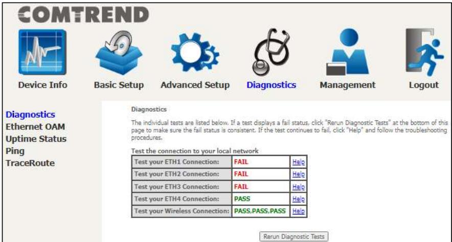
CHAPTER 7 DIAGNOSTICS. 144
7.1 DIAGNOSTICS - INDIVIDUAL TESTS 144
7.2 ETHERNET OAM 145
7.3 UPTIME STATUS 147
7.4PING 148
7.5TRACE ROUTE 149
CHAPTER 8 MANAGEMENT 150
8.1 SETTINGS 150
8.1.1 Backup Settings 150
8.1.2 Update Settings 151
8.1.3 Restore Default 151
2 SYSTEM LOG 153
8.3 SNMP AGENT 156
8.4 TR-069 CLIENT 157
8.5 STUN CLIENT 159
8.6 INTERNET TIME 160
8.7 ACCESS CONTROL 161
8.7.1 Accounts 161
8.7.2 Services 162
8.7.3 IP Address 163
8.8 UPDATE SOFTWARE 164
8.9 REBOOT 165
COMTREND
CHAPTER 9 LOGOUT. 166
APPENDIX A - FIREWALL 167
APPENDIX B - PIN ASSIGNMENTS 170
APPENDIX C - SPECIFICATIONS 171
APPENDIX D - SSH CLIENT 173
APPENDIX E - PRINTER SERVER 174
APPENDIX F - CONNECTION SETUP 181
COMTREND
Chapter 1 Introduction
PRT-6351 is a triple band Wi-Fi 6E Gateway with an updated silicon platform. It provides a 2.5 Giga Ethernet WAN port and four Giga Ethernet ports, supporting Wi-Fi 6 (802.11ax) Wireless solution on frequency band of 2.4GHz (4T4R), 5GHz (4T4R) and 6GHz (2T2R). PRT-6351 allows central management (ACS) by following TR-069.The core design concept of PRT-6351 is to enhance the user experience on high speed applications with its high power wireless design, so as to provide better coverage and stable Wi-Fi services.
Chapter 2 Installation
2.1 Hardware Setup

DO NOT STACK
Non-stackable
This device is not stackable - do not place units on top of each other, otherwise damage could occur.
Follow the instructions below to complete the hardware setup.
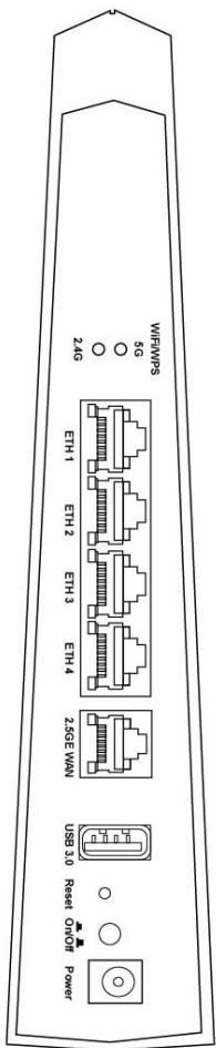
2.1.1 Back Panel
The figure below shows the back panel of the device.
WiFi On/Off Button
Press the button for more than 5 to enable/disable the WiFi function.
WPS Button
Press and release the button to enable WPS which will allow 2 minutes for WiFi connection.
Ethernet (LAN) Ports
Use 1000-BASE-T RJ-45 cables to connect up to four network devices to a Gigabit LAN, or 10/100BASE-T RJ-45 cables for slower networks. As these ports are autosensing MDI/X, either straight-through or crossover cable can be used.
COMTREND
GETH WAN PORT
This port is designated to be used for 2.5 Gigabit Ethernet WAN functionality only. Use an Ethernet RJ-45 cable to connect to Gigabit WAN server for standard network usage.
USB Port
This port can be used to connect the router to a storage device. It can only be used for SAMBA(storage) and for a Printer Server. Support for other devices may be added in future firmware upgrades.
Reset Button
Restore the default parameters of the device by pressing the Reset button for 10 seconds. After the device has rebooted successfully, the front panel should display as expected (see section 2.1.2 Front Panel for details).
NOTE: If pressed down for more than 60 seconds, the PRT-6351 will go into a firmware update state (CFE boot mode). The firmware can then be updated using an Internet browser pointed to the default IP address.
Power ON
Press the power button to the OFF position (OUT). Connect the power adapter to the power port. Attach the power adapter to a wall outlet or other AC source. Press the power button to the ON position (IN). If the Power LED displays as expected then the device is ready for setup (see section - LED Indicators).
Caution 1: If the device fails to power up, or it malfunctions, first verify that the power cords are connected securely and then power it on again. If the problem persists, contact technical support.
Caution 2: Before servicing or disassembling this equipment, disconnect all power cords and telephone lines from their outlets.
COMTREND
2.1.2 Front Panel
The front panel LED indicators are shown below and explained in the following table.
This information can be used to check the status of the device and its connections.

| LED | Color | Mode | Function |
| INTERNET | Green | On | IP connected and no traffic detected (the device has a WAN IP address from IPCP or DHCP is up or a static IP address is configured, PPP negotiation is successfully complete.) |
| If the IP or PPPoE session is dropped due to an idle timeout, the light will remain green. | |||
| Off | Modem power off, modem in WDS mode or WAN connection not present. |
COMTREND
| Blink | IP connected and IP Traffic is passing through the device (either direction) | ||
| Red | On | Device attempted to become IP connected and failed (no DHCP response, no PPPoE response, PPPoE authentication failed, no IP address from IPCP, etc.) | |
| 2.5G WAN | Green | On | Ethernet WAN is connected. |
| Off | Ethernet WAN is not connected. | ||
| Blink | Ethernet WAN is transmitting/ receiving. | ||
| 6G WiFi | Green | On | Wi-Fi enabled. |
| Off | Wi-Fi disabled. | ||
| Blink | Data transmitting or receiving over WLAN. | ||
| 5G WiFi | Green | On | Wi-Fi enabled. |
| Off | Wi-Fi disabled. | ||
| Blink | Data transmitting or receiving over WLAN. | ||
| 2.4G WiFi | Green | On | Wi-Fi enabled. |
| Off | Wi-Fi disabled. | ||
| Blink | Data transmitting or receiving over WLAN. | ||
| WPS | Green | On | WPS connection successful. The LED will stay on for three minutes. |
| Off | No WPS association process ongoing. | ||
| Slow Blink | WPS connection in progress. | ||
| Fast Blink | WPS connection unsuccessful. The LED will keep blinking until client is connected. | ||
| ETH 1X-4X | Green | On | An Ethernet Link is established. |
| Off | An Ethernet Link is not established. | ||
| Blink | Data transmitting or receiving over Ethernet. | ||
| USB | Green | On | At least one device is connected to any USB ports. |
| Off | No device is connected to the USB port or a device is connected to the USB port but not active. | ||
| Blink | Data TX/RX through the USB port. | ||
| POWER | Green | On | The device is powered up. |
| Off | The device is powered down. | ||
| Red | On | POST (Power On Self Test) failure or other malfunction. A malfunction is any error of internal sequence or state that will prevent the device from connecting to the DSLAM or passing customer data. |
COMTREND
Note:
A malfunction is any error of internal sequence or state that will prevent the device from connecting to the DSLAM or passing customer data. This may be identified at various times such after power on or during operation through the use of self testing or in operations which result in a unit state that is not expected or should not occur.
COMTREND
Chapter 3 Web User Interface
This section describes how to access the device via the web user interface (WUI) using an Internet browser such as Internet Explorer (version 5.0 and later).
3.1 Default Settings
The factory default settings of this device are summarized below.
LAN IP address: 192.168.1.1
LAN subnet mask: 255.255.255.0
- Administrative access (username: root, password: 12345)
- WLAN access: enabled
Technical Note
During power on, the device initializes all settings to default values. It will then read the configuration profile from the permanent storage section of flash memory. The default attributes are overwritten when identical attributes with different values are configured. The configuration profile in permanent storage can be created via the web user interface or telnet user interface, or other management protocols. The factory default configuration can be restored either by pushing the reset button for more than ten seconds until the power indicates LED blinking or by clicking the Restore Default Configuration option in the Restore Settings screen.
3.2 IP Configuration
DHCP MODE
When the PRT-6351 powers up, the onboard DHCP server will switch on. Basically, the DHCP server issues and reserves IP addresses for LAN devices, such as your PC.
To obtain an IP address from the DCHP server, follow the steps provided below.
NOTE: The following procedure assumes you are running Windows. However, the general steps involved are similar for most operating systems (OS). Check your OS support documentation for further details.
STEP 1: From the Network Connections window, open Local Area Connection (You may also access this screen by double-clicking the Local Area Connection icon on your taskbar). Click the Properties button.
STEP 2: Select Internet Protocol (TCP/IP) and click the Properties button.
STEP 3: Select Obtain an IP address automatically as shown below.
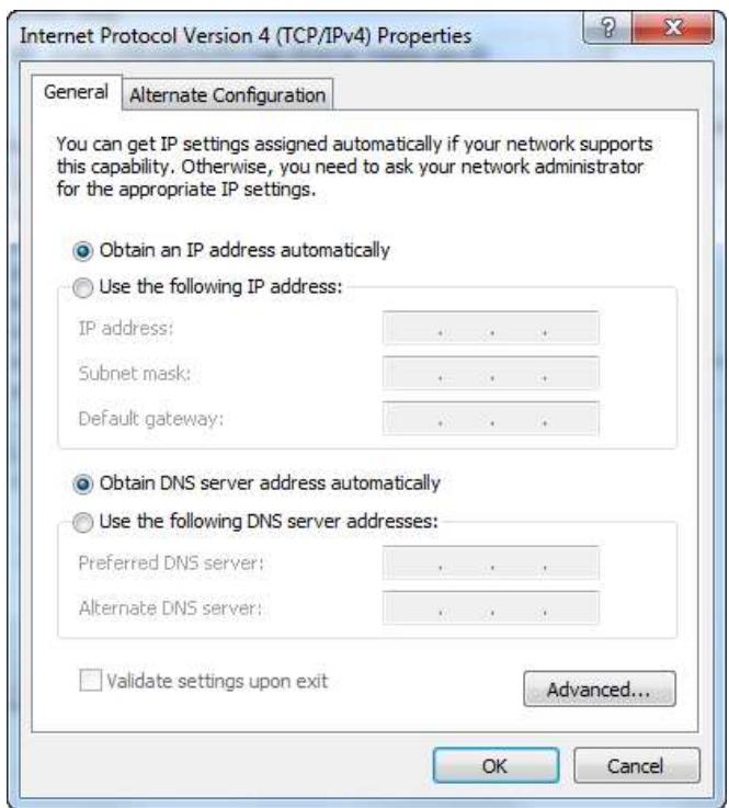
STEP 4: Click OK to submit these settings.
If you experience difficulty with DHCP mode, you can try static IP mode instead.
STATIC IP MODE
In static IP mode, you assign IP settings to your PC manually.
Follow these steps to configure your PC IP address to use subnet 192.168.1.x.
NOTE: The following procedure assumes you are running Windows. However, the general steps involved are similar for most operating systems (OS). Check your OS support documentation for further details.
STEP 1: From the Network Connections window, open Local Area Connection (You may also access this screen by double-clicking the Local Area Connection icon on your taskbar). Click the Properties button.
STEP 2: Select Internet Protocol (TCP/IP) and click the Properties button.
STEP 3: Change the IP address to the 192.168.1.x (1<x<255) subnet with subnet mask of 255.255.255.0. The screen should now display as shown below.
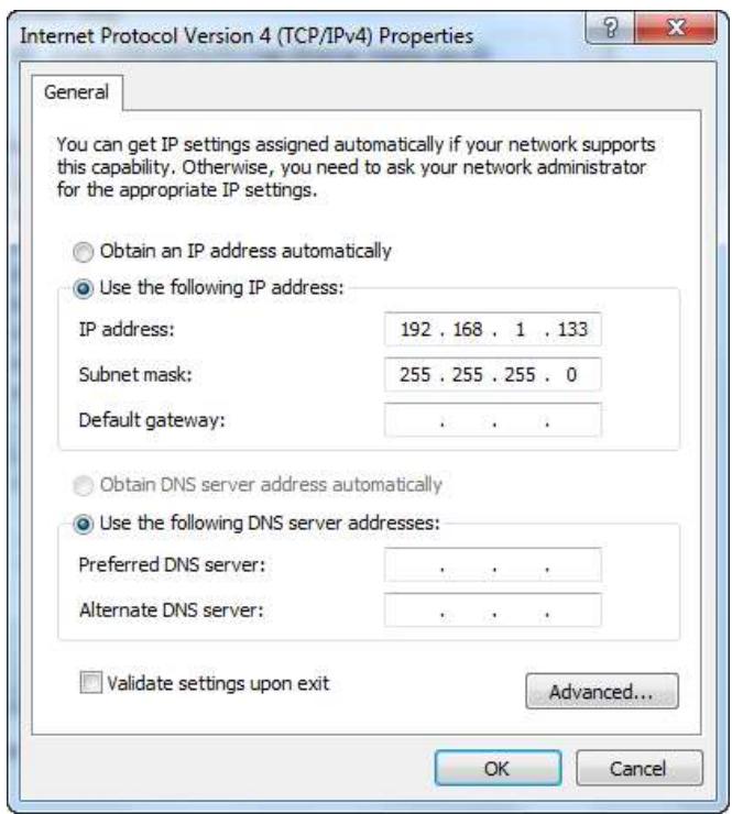
STEP 4: Click OK to submit these settings.
COMTREND
3.3 Login Procedure
Perform the following steps to login to the web user interface.
NOTE: The default settings can be found in section 3.1 Default Settings.
STEP 1: Start the Internet browser and enter the default IP address for the device in the Web address field. For example, if the default IP address is 192.168.1.1, type http://192.168.1.1.
NOTE: For local administration (i.e. LAN access), the PC running the browser must be attached to the Ethernet, and not necessarily to the device. For remote access (i.e. WAN), use the IP address shown on the Device Information screen and login with remote username and password.
STEP 2: A dialog box will appear, such as the one below. Enter the default username and password, as defined in section 3.1 Default Settings.
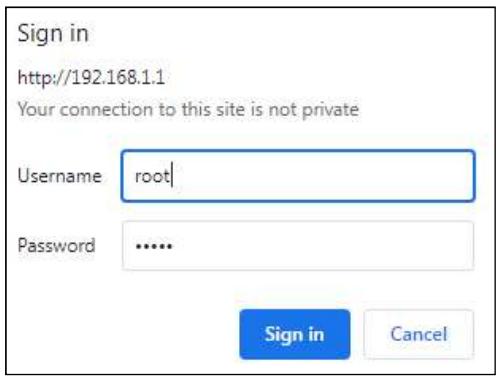
Click OK to continue.
NOTE: The login password can be changed later (see section 8.7.1 Accounts).
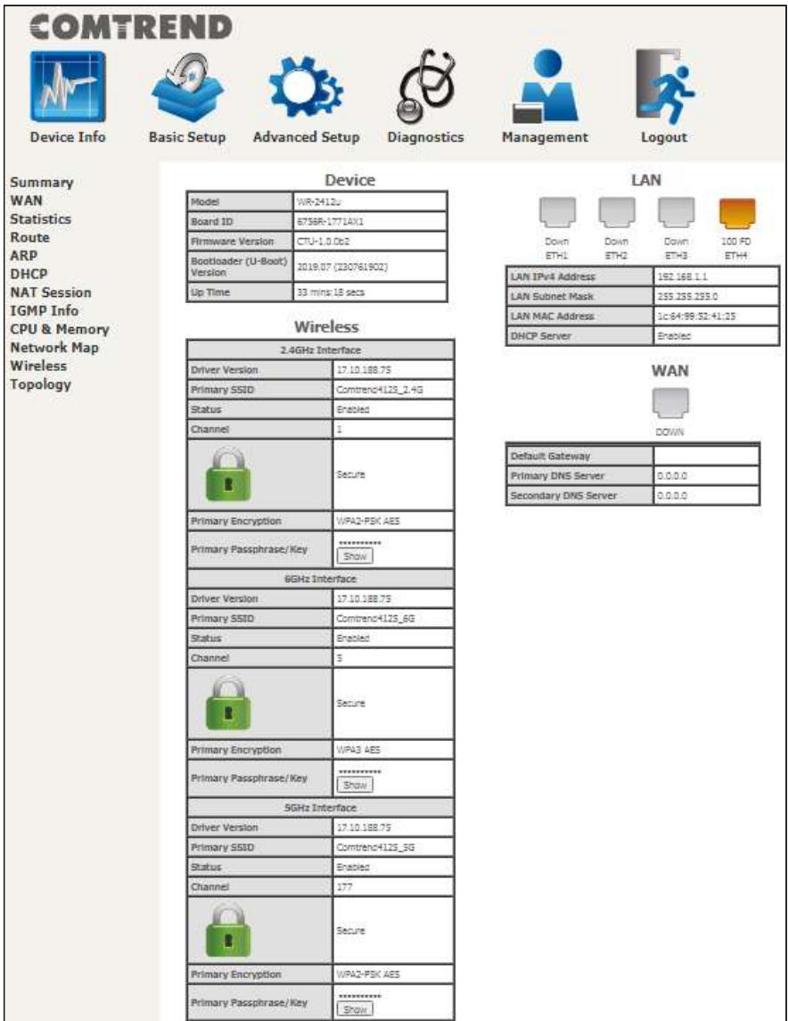
STEP 3: After successfully logging in for the first time, you will reach this screen.
You can also reach this page by clicking on the following icon located at the top of the screen.
COMTREND

Device Info
COMTREND
Chapter 4 Device Information
You can reach this page by clicking on the following icon located at the top of the screen.

Device Info
The web user interface window is divided into two frames, the main menu (on the left) and the display screen (on the right). The main menu has several options and selecting each of these options opens a submenu with more selections.
NOTE: The menu items shown are based upon the configured connection(s) and user account privileges. For example, user account has limited access to configuration modification.
Device Info is the first selection on the main menu so it will be discussed first. Subsequent chapters will introduce the other main menu options in sequence.
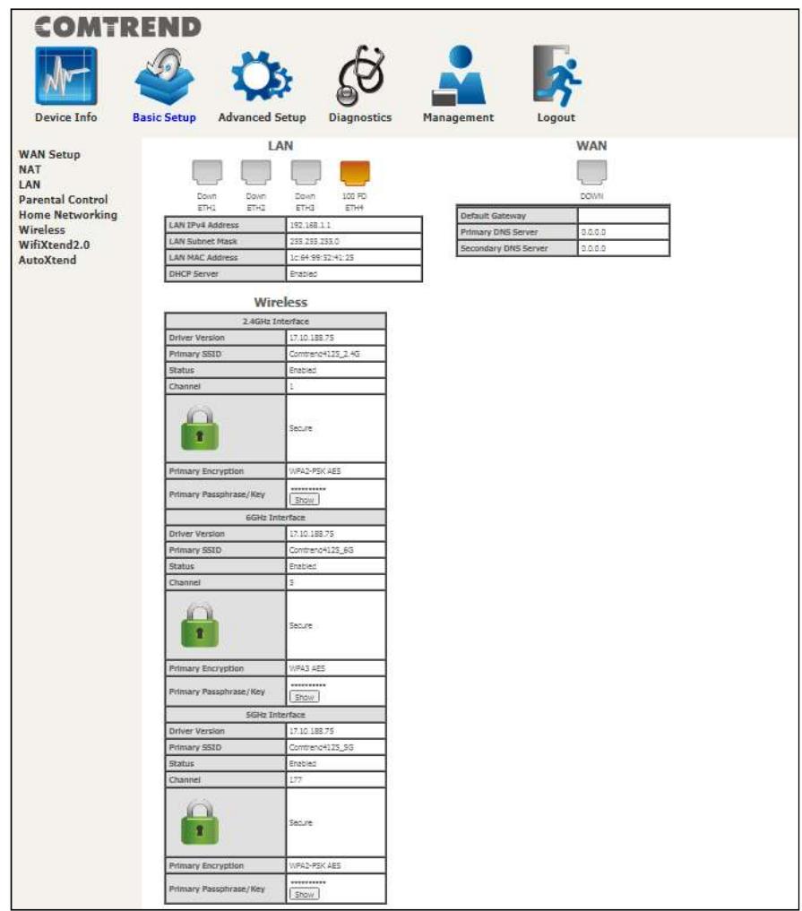
The Device Info Summary screen displays at startup.
COMTREND
COMTREND

Device Info

Basic Setup

Advanced Setup

Diagnostics

Management

Logout
Summary
WAN
Statistics
Route
ARP
DHC
NAT Session
IGMP Info
CPU & Memory
Network Map
Wireless
Topology
Device
| Model | WR-2412u |
| Board ID | 6758R-17714X1 |
| Firmware Version | CTU-1.0.0c2 |
| BootIsader (U-Boot) Version | 2019.07 (230761902) |
| Up Time | 33 mins:18 sets |
Wireless
| 2.4GHz Interface | |
| Driver Version | 17.10.188.7S |
| Primary SSD | Comtrend4125_2-4G |
| Status | Enabled |
| Channel | 1 |
| Secure | |
| Primary Encryption | WPA2-PSK AES |
| Primary Passphrase/Key | Show |
| 6GHz Interface | |
| Driver Version | 17.10.188.7S |
| Primary SSD | Comtrend4125_6G |
| Status | Enabled |
| Channel | 3 |
| Secure | |
| Primary Encryption | WPA3 AES |
| Primary Passphrase/Key | Show |
| 5GHz Interface | |
| Driver Version | 17.10.188.7S |
| Primary SSD | Comtrend4125_3G |
| Status | Enabled |
| Channel | 177 |
| Secure | |
| Primary Encryption | WPA2-PSK AES |
| Primary Passphrase/Key | Show |
LAN
| LAN IPv4 Address | 192.168.1.1 |
| LAN Subnet Mask | 255.235.235.0 |
| LAN MAC Address | 1c:64:89:52:41:25 |
| DHCP Server | Ethernet |
WAN
| Default Gateway | |
| Primary DNS Server | 0.0.0.0 |
| Secondary DNS Server | 0.0.0.0 |
This screen shows hardware, software, IP settings and other related information.
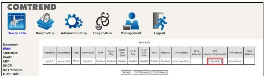
4.1 WAN
Select WAN from the Device Info submenu to display the configured PVC(s).
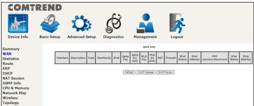
Refresh - Click this button to refresh the screen.
DHCP Release - Click this button to release the IP through IPOE service.
DHCP Renew - Click this button to refresh an IP through IPOE service.
COMTREND
For your reference, if Manual Mode is enabled in PPP service as shown here.
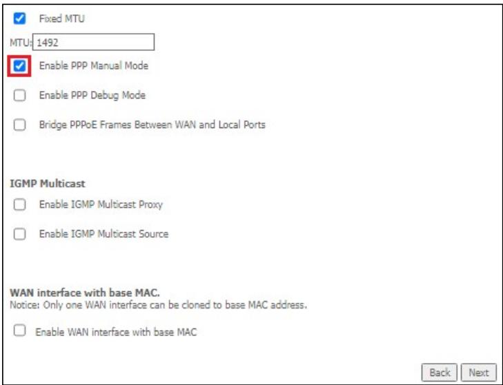
Manual PPP connect/disconnect option will become available on the WAN Info page (as shown here).
4.2 Statistics
This selection provides LAN and WAN statistics.
NOTE: These screens are updated automatically every 15 seconds. Click Reset Statistics to perform a manual update.
4.2.1 LAN Statistics
This screen shows data traffic statistics for each LAN interface.
| COMTREND | ||||||||||||||
| Device Info | Basic Setup | Advanced Setup | Diagnostics | Management | Logout | |||||||||
| Summary WAN Statistics LAN WAN Service Route ARP DHCP NAT Session IGMP Info CPU & Memory Network Map Wireless Topology | Statistics -- LAN | |||||||||||||
| Interface | Received | Transmitted | ||||||||||||
| Total | Multicast | Unicast | Broadcast | Total | Multicast | Unicast | ||||||||
| Bytes | Pkts | Errs | Drops | Bytes | Pkts | Pkts | Pkts | Bytes | Pkts | Errs | Drops | Pkts | ||
| ETHWAN | 0 | 0 | 0 | 0 | 0 | 0 | 0 | 0 | 0 | 0 | 0 | 0 | 0 | |
| ETH1 | 0 | 0 | 0 | 0 | 0 | 0 | 0 | 0 | 0 | 0 | 0 | 0 | 0 | |
| ETH2 | 0 | 0 | 0 | 0 | 0 | 0 | 0 | 0 | 0 | 0 | 0 | 0 | 0 | |
| ETH3 | 0 | 0 | 0 | 0 | 0 | 0 | 0 | 0 | 0 | 0 | 0 | 0 | 0 | |
| ETH4 | 181530 | 986 | 0 | 0 | 0 | 67 | 868 | 51 | 493448 | 1097 | 0 | 0 | 95 | |
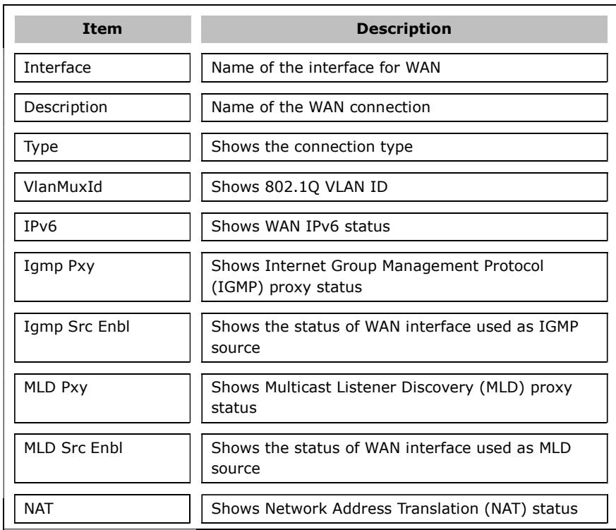
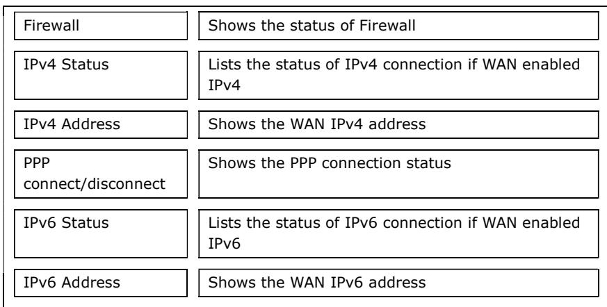
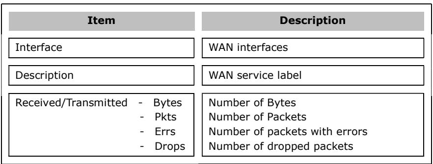
| Item | Description |
| Interface | LAN interface(s) |
| Received/Transmitted: - Bytes | Number of Bytes |
| - Pkts | Number of Packets |
| - Errs | Number of packets with errors |
| - Drops | Number of dropped packets |
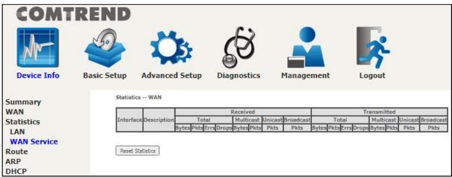
4.2.2 WAN Service
This screen shows data traffic statistics for each WAN interface.
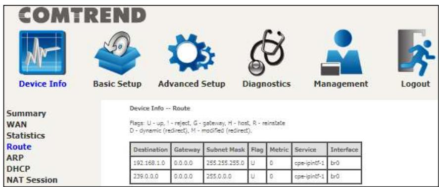
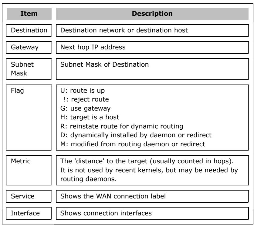
4.3 Route
Choose Route to display the routes that the PRT-6351 has found.
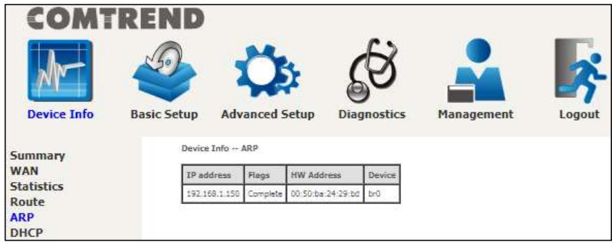
4.4 ARP
Click ARP to display the ARP information.
4.5 DHCP
Click DHCP to display all DHCP Leases.

COMTREND
Device Info

Basic Setup

Advanced Setup

Diagnostics

Management

Logout
Summary
WAN
Statistics
Route
ARP
DHCP
Device Info - DHCP Leases
| Hostname | MAC Address | IP Address | Address Source | Interface Type | Status | Expires In | Tx bytes | Rx bytes |
Item
Description
Hostname
Shows the device/host/PC network name
MAC
Address
Shows the Ethernet MAC address of the device/host/PC
IP Address
Shows IP address of device/host/PC
Address
Source
Shows IP type of device/host/PC, could be DHCP/Static
Interface
Shows interface type of device/host/PC, could be
Type
Ethernet/802.11
Status
Show status of device/host/PC, could be active/inactive
Expires In
Shows how much time is left for each DHCP Lease
Tx bytes
Show total Tx bytes of device/host/PC
Rx bytes
Show total Rx bytes of device/host/PC
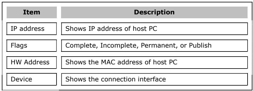
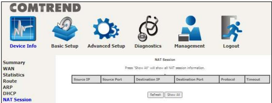
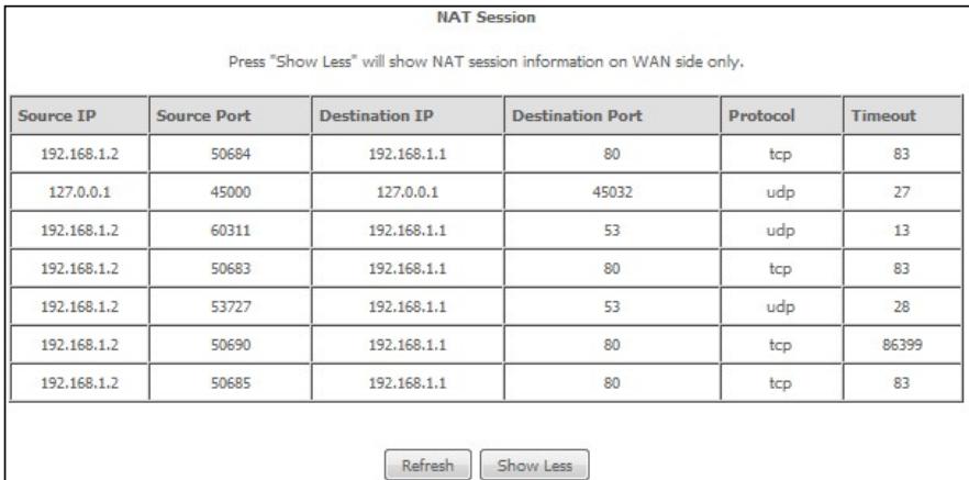
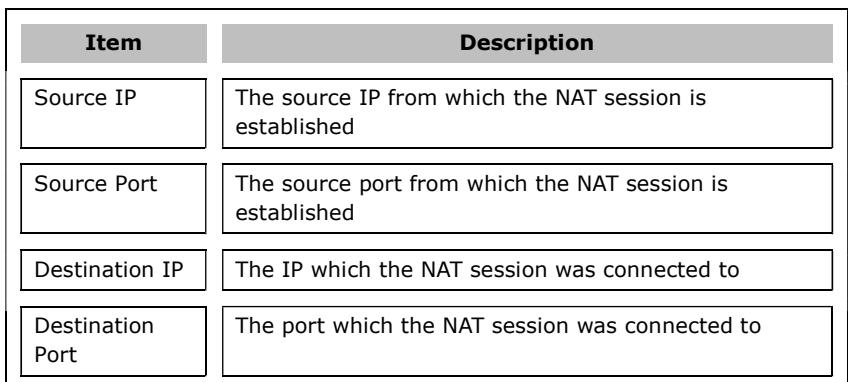
4.6 NAT Session
This page displays all NAT connection session including both UPD/TCP protocols passing through the device.
Click the "Show All" button to display the following.
COMTREND
Protocol
The Protocol used in establishing the particular NAT session
Timeout
The time remaining for the TCP/UDP connection to be active
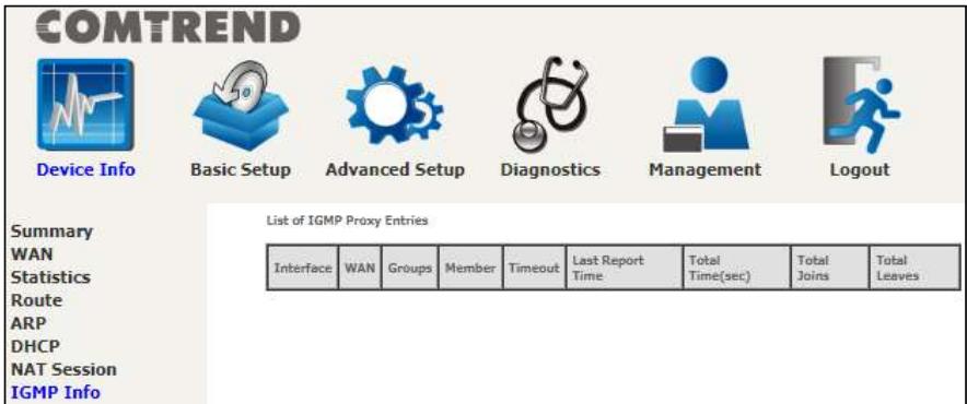
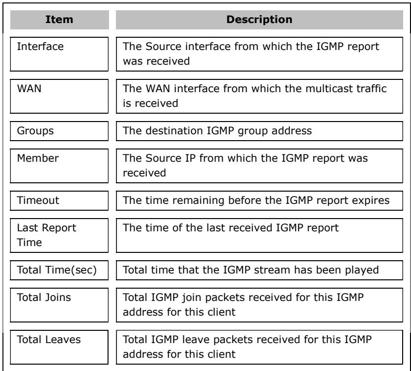
4.7 IGMP Info
Click IGMP Info to display the list of IGMP entries broadcasting through the IGMP proxy enabled WAN connection.
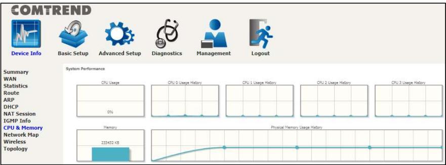
4.8 CPU & Memory
Displays the system performance graphs. Shows the current loading of the CPU and memory usage with dynamic updates.
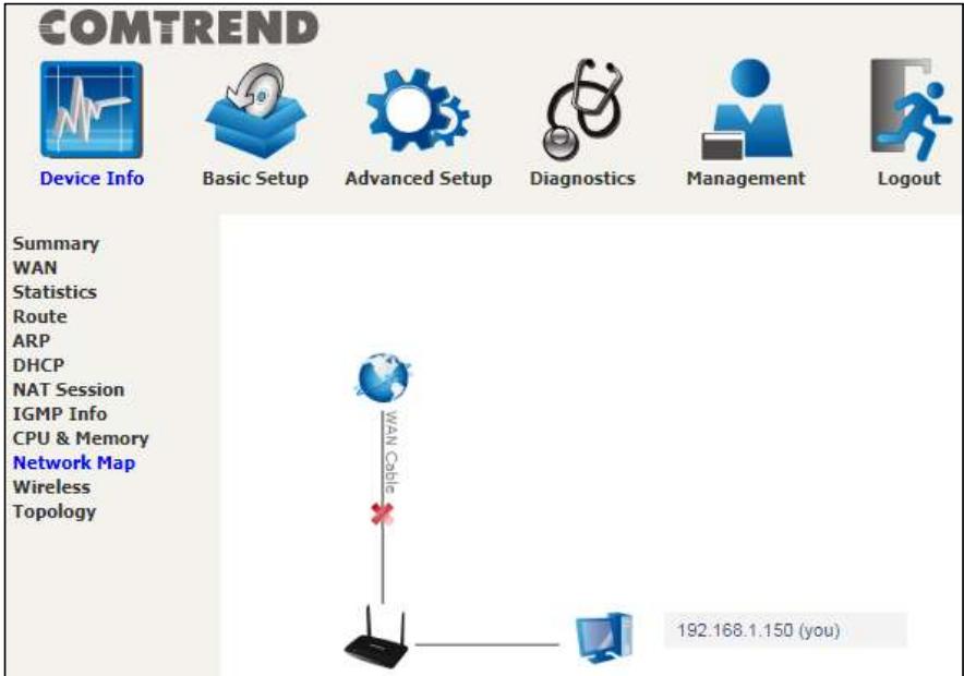
4.9 Network Map
The network map is a graphical representation of router's wan status and LAN devices.
4.10 Wireless
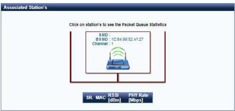
4.10.1 Station Info
This page shows authenticated wireless stations and their status.
COMTREND

Device Info

Basic Setup

Advanced Setup

Diagnostics

Management

Logout
Summary
WAN
Statistics
Route
ARP
DHCP
NAT Session
IGMP Info
CPU & Memory
Network Map
Wireless
Station Info
Wifi Insight
Topology
Station Info
This page allows you to configure the Virtual interfaces for each Physical interface
Wireless Interface:
BSS-MAC (SSID):
Authenticated Stations:
Comtrend4125 2.4G(1C:64:99:52:41:26)
1C:64:99:52:41:26 (Comtrend4125_2.4G enabled)
| MAC Address | Association Time | Authorized | WMM Link | Power Save | Spec | BW | Dwds | Rsi |
Item
MAC Address
Association Time
Description
Lists the MAC address of all the stations.
Lists all the stations that are associated with the Access
Point, along with the amount of time since packets were transferred to and from each station. If a station is idle for too long, it is removed from this list.
Authorized
WMM Link
Power Save
Spec
Lists those devices with authorized access
Lists those devices that utilize WMM
Lists those devices that utilize the Power Save Feature
Wi-Fi Spec
BW
Bandwidth
Dwds
Lists the devices that utilize Dynamic WDS
Rssi
Received Signal Strength Indicator
4.10.2 WiFi Insight
This page allows you to configure the WiFi Insight system. The WiFi Insight system allows the wireless interface to collect beacon data from nearby devices and analyze traffic on the connected stations. This data collection requires memory storage and therefore needs to be configured prior to use. To begin, click on the "Start Data Collection" button if no change is needed.
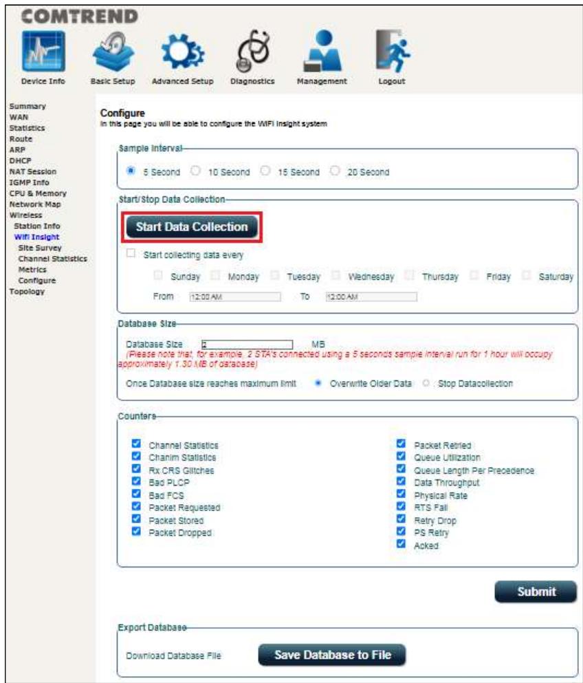
Sample Interval
Select a desired sample interval (time interval) to collect sampling data with the
COMTREND
WiFi insight system.
Start/Stop Data Collection
Check the checkbox of Start collecting data every (then select days & times).
Database Size
Define the dedicated database size to be used for the WiFi insight system (default is 2MB). Once the database size has reached its limit, select if you wish to overwrite older data or to stop data collection.
Counters
All counter options are selected (checked) by default. Uncheck any counters that that you do not want collected by the WiFi insight system. Click the Submit button to save your settings.
Export Database
Click the Save Database to File button to export and save the collected Wi-Fi data information file.
4.10.2.1 Site Survey
The graph displays wireless APs found in your neighborhood by channel collected under the WiFi insight system.
2.4GHz
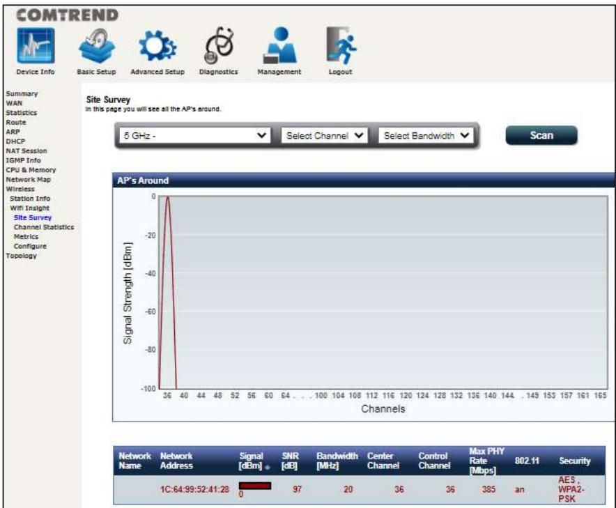
Select the wireless network (2.4GHz in above example) that you wish to monitor from the drop-down menu.
- Select the channel that you wish to monitor from the drop-down menu.
- Select a bandwidth of the wireless network from the drop-down menu.
- Click the Scan button to run the scan and display the results based on your selected preferences.
Consult the table below for descriptions of each column heading.
COMTREND
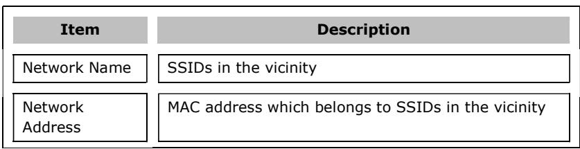
| Signal [dBm] | Signal Strength of each SSID |
| SNR [dB] | Signal-to-Noise Ratio of each SSID |
| Bandwidth [MHz] | Bandwidth of each SSID |
| Center Channel | Center Channel of each SSID |
| Control Channel | Control Channel of each SSID |
| Max PHY Rate [Mbps] | Max PHY Rate of each SSID |
| 802.11 | 802.11 type of each SSID |
| Security | Wi-Fi password encryption type of each SSID |
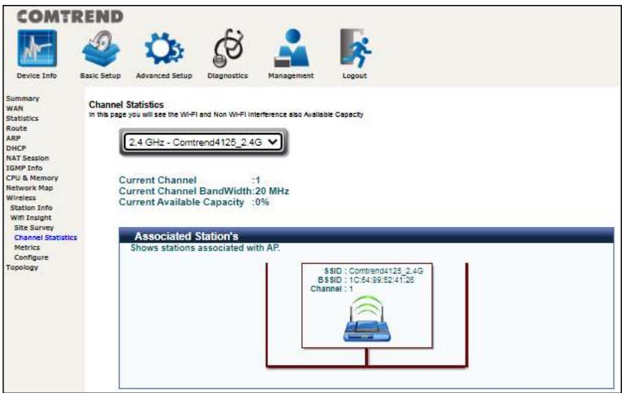
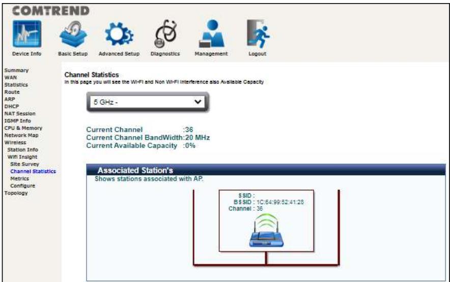
4.10.2.2 Channel Statistics
This page allows you to see the Wi-Fi and Non Wi-Fi interference, and also the available capacity. This page is broken down into individual parts below.
Click on the drop-down menu to select 2.4GHz or 5GHz interface.
2.4 GHz
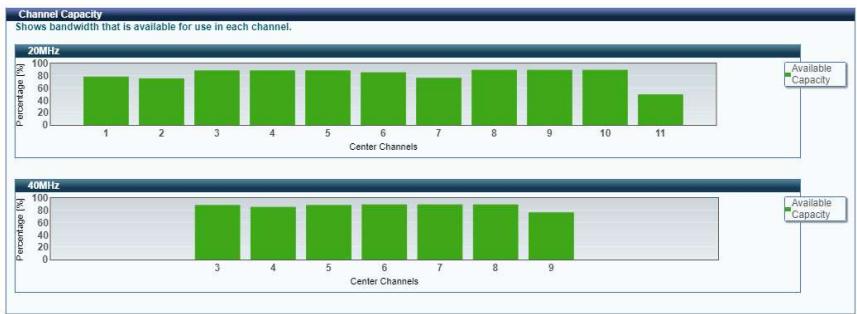
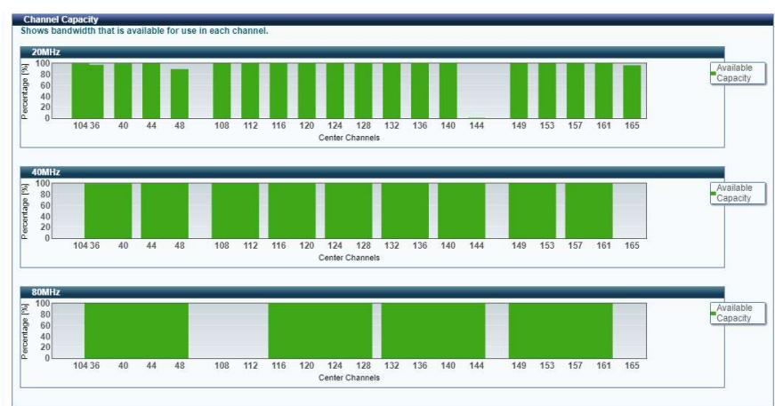
Shows the bandwidth that is available for use in each channel.
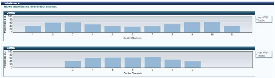
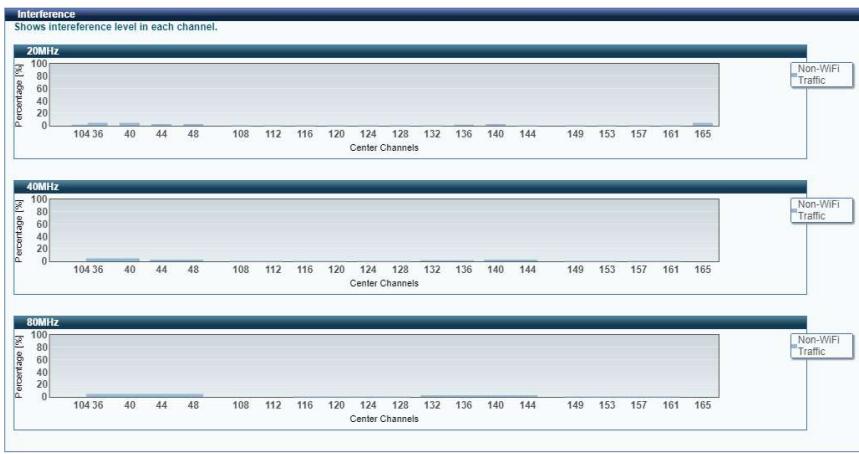
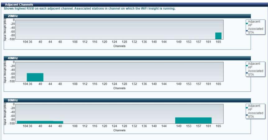
Shows interference level in each channel.
Shows the highest RSSI (Received Signal Strength Indicator) on each adjacent channel. Adjacent AP and associated stations are displayed for checking interference on those channels.
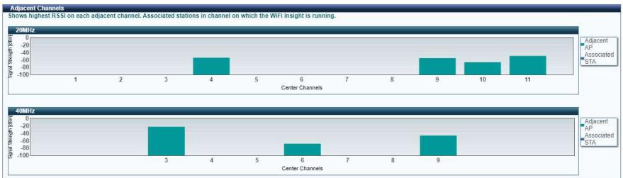
5 GHz
Shows the bandwidth that is available for use in each channel.
Shows interference level in each channel.
Shows the highest RSSI (Received Signal Strength Indicator) on each adjacent channel. Adjacent AP and associated stations are displayed for checking interference on those channels.
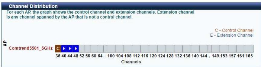
For each AP, the graph shows the control channel and extension channels. Extension channel is any channel spanned by the AP that is not a control channel.
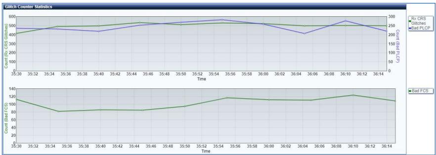
4.10.2.3 Metrics (Advanced Troubleshooting)
In this page you will see most of the counters like AMPDU(if available), Glitch, Chanim and Packet Queue Statistics. This page is broken down into individual parts below.
Advanced Troubleshooting
In this page you will see most of the counters like AMPDU(if available), Glitch, Chanim and Packet Queue Statistics
5 GHz - Comtrend5501 5GHz
Click on the drop-down menu to select 2.4GHz or 5GHz interface.
Shows the rx glitch counters, bad frame check sequence counters received from air over time.
Select the counter of interest to monitor the statistics received over time in the chanim statistics graph.
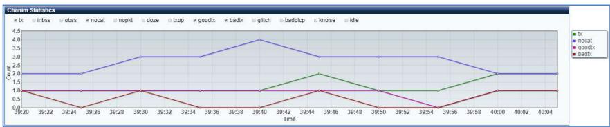
Lists the associated station to the wireless interface.
4.10.2.4 Configure
This page allows you to configure the WiFi Insight system. The WiFi Insight system allows the wireless interface to collect beacon data from nearby devices and analyze traffic on the connected stations. This data collection requires memory storage and therefore needs to be configured prior to use. To begin, click on the "Start Data Collection" button if no change is needed.
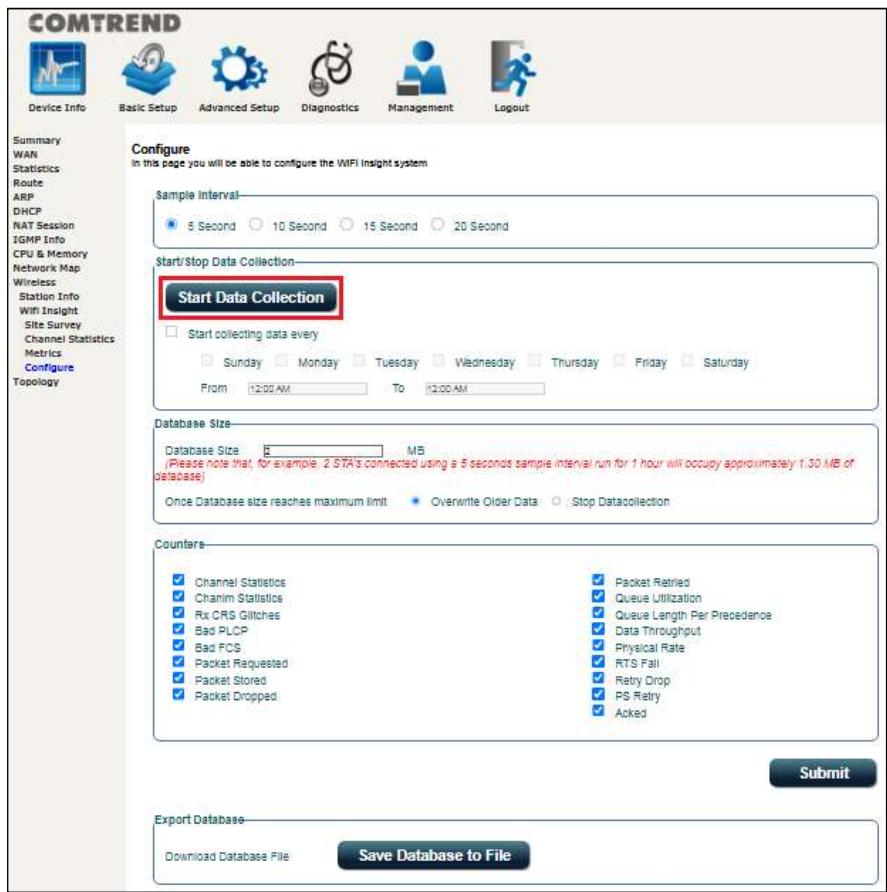
Sample Interval
Select a desired sample interval (time interval) to collect sampling data with the WiFi insight system.
Start/Stop Data Collection
Check the checkbox of Start collecting data every (then select days & times).
Database Size
Define the dedicated database size to be used for the WiFi insight system (default is 2MB). Once the database size has reached its limit, select if you wish to overwrite older data or to stop data collection.
COMTREND
Counters
All counter options are selected (checked) by default. Uncheck any counters that that you do not want collected by the WiFi insight system. Click the Submit button to save your settings.
Export Database
Click the Save Database to File button to export and save the collected Wi-Fi data information file.
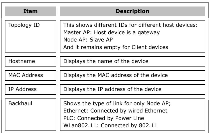
4.11 Topology
This displays the arrangement of devices of the communication network. The dotted line represents a wireless connection, whereas a solid line represents a wired connection.
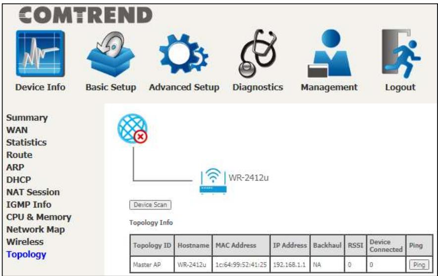
Click the Device Scan button to scan for the network topology.
Consult the table below for descriptions of each column heading.
COMTREND
RSSI
Displays the received signal strength indicator (signal strength) for the device
Device
Displays the number of devices connected
Connected
Ping
Click the button and follow the onscreen
instructions to ping a device.
Chapter 5 Basic Setup
You can reach this page by clicking on the following icon located at the top of the screen.

Basic Setup
This will bring you to the following screen.
5.1 WAN Setup
- Click WAN Setup on the on the left of your screen
Add or remove ETH WAN interface connections here.
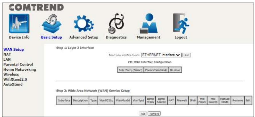
Click Add to create a new Layer 2 Interface (see Appendix F - Connection Setup).
To remove a connection, click the Remove button.
5.1.1 WAN Service Setup
This screen allows for the configuration of WAN interfaces.
| Interface | Description | Type | Vlan8021p | VlanMuxId | VlanTpid | Igmp Proxy | Igmp Source | NAT | Firewall | IPv6 | Mld Proxy | Mld Source | Manual Mode | Remove | Edit |
| eth0.1 | ipoe_ether | IPoe | N/A | N/A | N/A | Disabled | Disabled | Enabled | Disabled | Disabled | Disabled | Disabled | Disabled | Edit | |
Click the Add button to create a new connection. For connections on ATM or PTM or ETH WAN interfaces see Appendix F - Connection Setup.
| Interface | Description | Type | Vlan8021p | VlanMuxId | VlanTpid | Igmp Proxy | Igmp Source | NAT | Firewall | IPv6 | Mid Proxy | Mid Source | Manual Mode | Remove | Edit |
| eth0.1 | ipoe_ether | IPoE | N/A | N/A | N/A | Disabled | Disabled | Enabled | Disabled | Disabled | Disabled | Disabled | Disabled | √ | Edit |
| Add Remove | |||||||||||||||
To remove a connection, select its Remove column radio button and click Remove.
| Item | Description |
| Interface | Name of the interface for WAN |
| Description | Name of the WAN connection |
| Type | Shows the connection type |
| Vlan8021p | VLAN ID is used for VLAN Tagging (IEEE 802.1Q) |
| VlanMuxId | Shows 802.1Q VLAN ID |
| VlanTpid | VLAN Tag Protocol Identifier |
| IGMP Proxy | Shows Internet Group Management Protocol (IGMP) Proxy status |
| IGMP Source | Shows the status of WAN interface used as IGMP source |
| NAT | Shows Network Address Translation (NAT) status |
| Firewall | Shows the Security status |
| IPv6 | Shows the WAN IPv6 address |
| MLD Proxy | Shows Multicast Listener Discovery (MLD) Proxy status |
| Mld Source | Shows the status of WAN interface used as MLD source |
| Manual Mode | Indicates the status of the PPP manual connect/disconnect button |
| Remove | Select interfaces to remove |
COMTREND
Edit
Click the Edit button to make changes to the WAN interface
To remove a connection, select its Remove column radio button and click Remove.
NOTE: Up to 16 PVC profiles can be configured and saved in flash memory.
5.2 NAT
For NAT features under this section to work, NAT must be enabled in at least one PVC.
5.2.1 Virtual Servers
Virtual Servers allow you to direct incoming traffic from the WAN side (identified by Protocol and External port) to the internal server with private IP addresses on the LAN side. The Internal port is required only if the external port needs to be converted to a different port number used by the server on the LAN side. A maximum of 32 entries can be configured.
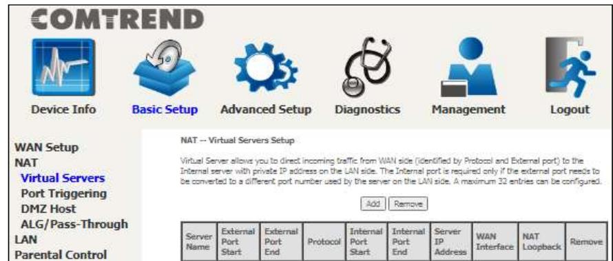
To add a Virtual Server, click Add. The following will be displayed.
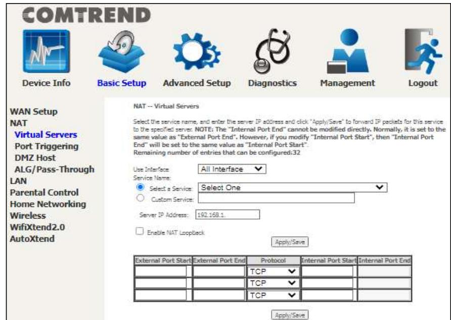
Click Apply/Save to apply and save the settings.
Consult the table below for item descriptions.
| Item | Description |
| Use Interface | Select a WAN interface from the drop-down menu. If you choose All Interface, server rules will be created for all WAN interfaces. |
| Select a Service Or Custom Service | User should select the service from the list. Or User can enter the name of their choice. |
| Server IP Address | Enter the IP address for the server. |
| Enable NAT Loopback | Allows local machines to access virtual server via WAN IP Address |
| External Port Start | Enter the starting external port number (when you select Custom Server). When a service is selected, the port ranges are automatically configured. |
| External Port End | Enter the ending external port number (when you select Custom Server). When a service is selected, the port ranges are automatically configured. |
| Protocol | TCP, TCP/UDP, or UDP. |
| Internal Port Start | Enter the internal port starting number (when you select Custom Server). When a service is selected the port ranges are automatically configured |
| Internal Port End | Enter the internal port ending number (when you select Custom Server). When a service is selected, the port ranges are automatically configured. |
5.2.2 Port Triggering
Some applications require that specific ports in the firewall be opened for access by the remote parties. Port Triggers dynamically 'Open Ports' in the firewall when an application on the LAN initiates a TCP/UDP connection to a remote party using the 'Triggering Ports'. The Router allows the remote party from the WAN side to establish new connections back to the application on the LAN side using the 'Open Ports'. A maximum 32 entries can be configured.
COMTREND

Device Info

Basic Setup

Advanced Setup

Diagnostics

Management

Logout
WAN Setup
NAT
Virtual Servers
Port Triggering
DMZ Host
ALG/Pass-Through
LAN
Parental Control
Home Networking
Wireless
WifiXtend2.0
AutoXtend
NAT - Port Triggering Setup
Some applications require that specific ports in the Router's firewall be opened for access by the remote parties. Port Trigger dynamically opens up the Open Ports in the firewall when an application on the LAN initiates a TCP/UDP connection to a remote party using the Triggering Ports. The Router allows the remote party from the WAN side to establish new connections back to the application on the LAN side using the Open Ports. A maximum 32 entries can be configured.

| Application Name | Trigger | Open | WAN Interface | Remove | ||||
| Protocol | Port Range | Protocol | Port Range | |||||
| Start | End | Start | End | |||||
To add a Trigger Port, click Add. The following will be displayed.
COMTREND

Device Info

Basic Setup

Advanced Setup

Diagnostics

Management

Logout
WAN Setup
NAT
Virtual Servers
Port Triggering
DMZ Host
ALG/Pass-Through
LAN
Parental Control
Home Networking
Wireless
WifiXtend2.0
AutoXtend
NAT - Port Triggering
Some applications such as games, video conferencing, remote access applications and others require that specific ports in the Router's firewall be opened for access by the applications. You can configure the port settings from this screen by selecting an existing application or creating your own (Custom application) and click "Save/Apply" to add it.
Remaining number of entries that can be configured:32
Use Interface
Application Name:


| Trigger Port Start | Trigger Port End | Trigger Protocol | Open Port Start | Open Port End | Open Protocol | |||
| TCP | ✓ | TCP | ||||||
| TCP | ✓ | TCP | ||||||
| TCP | ✓ | TCP | ||||||

Click Save/Apply to save and apply the settings.
Consult the table below for item descriptions.
| Item | Description |
| Use Interface | Select a WAN interface from the drop-down menu. |
| Select an Application Or Custom Application | User should select the application from the list. Or User can enter the name of their choice. |
| Trigger Port Start | Enter the starting trigger port number (when you select custom application). When an application is selected, the port ranges are automatically configured. |
| Trigger Port End | Enter the ending trigger port number (when you select custom application). When an application is selected, the port ranges are automatically configured. |
| Trigger Protocol | TCP, TCP/UDP, or UDP. |
| Open Port Start | Enter the starting open port number (when you select custom application). When an application is selected, the port ranges are automatically configured. |
| Open Port End | Enter the ending open port number (when you select custom application). When an application is selected, the port ranges are automatically configured. |
| Open Protocol | TCP, TCP/UDP, or UDP. |
5.2.3 DMZ Host
The DSL router will forward IP packets from the WAN that do not belong to any of the applications configured in the Virtual Servers table to the DMZ host computer.
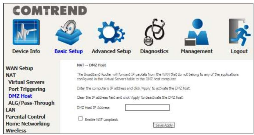
To Activate the DMZ host, enter the DMZ host IP address and click Save/Apply.
To Deactivate the DMZ host, clear the IP address field and click Save/Apply.
Enable NAT Loopback: Check the checkbox to allow local machines to access virtual server via WAN IP Address.
5.2.4 ALG/Pass-Through
Support ALG Pass-through for the listed protocols.
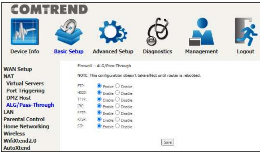
To allow/deny the corresponding ALG protocol, select Enable / Disable and then click the Save button. After reboot, the protocol will be added/removed to/from the system module.
5.3 LAN
Configure the LAN interface settings and then click Apply/Save.
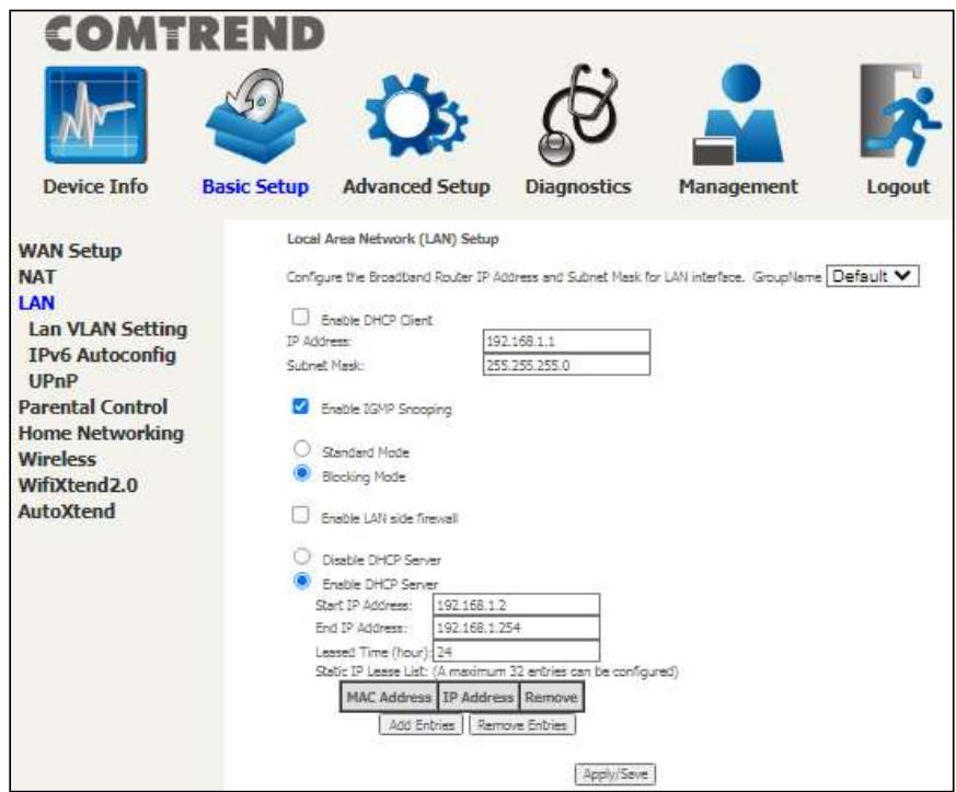
The settings shown above are described below.
GroupName: Select an Interface Group.
1st LAN INTERFACE
Enable DHCP Client: Enable by checking the checkbox 1
IP Address: Enter the IP address for the LAN port.
Subnet Mask: Enter the subnet mask for the LAN port.
Enable IGMP Snooping: Enable by checking the checkbox l
Standard Mode: In standard mode, multicast traffic will flood to all bridge ports when no client subscribes to a multicast group - even if IGMP snooping is enabled.
Blocking Mode: In blocking mode, the multicast data traffic will be blocked and not flood to all bridge ports when there are no client subscriptions to any multicast group.
Enable LAN side firewall: Enable by ticking the checkbox l
DHCP Server: To enable DHCP, select Enable DHCP server and enter Start and End IP addresses and the Leased Time. This setting configures the router to automatically assign IP, default gateway and DNS server addresses to every PC on your LAN.
Setting TFTP Server: Enable by ticking the checkbox☑. Then, input the TFTP server address or an IP address.
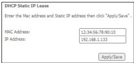
Static IP Lease List: A maximum of 32 entries can be configured.
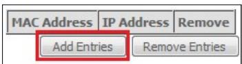
To add an entry, enter MAC address and Static IP and then click Apply/Save.
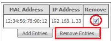
To remove an entry, tick the corresponding checkbox l in the Remove column and then click the Remove Entries button, as shown below.
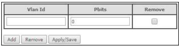
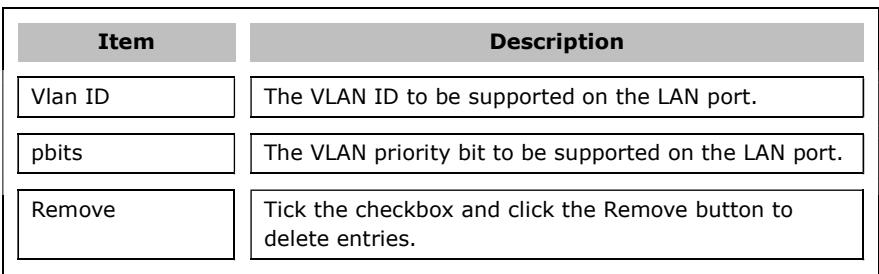
5.3.1 Lan VLAN Setting
The CPE will tag VLAN on specific LAN port(s) when this feature is used.
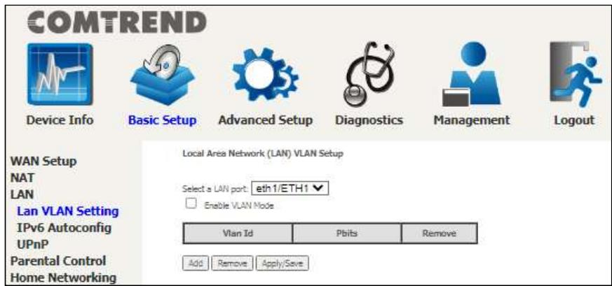
To enable VLAN Mode, check the checkbox and click the Apply/Save button.
Click the Add button to display the following.
5.3.2 LAN IPv6 Autoconfig
Configure the LAN interface settings and then click Save/Apply.
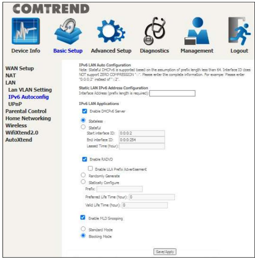
The settings shown above are described below.
Static LAN IPv6 Address Configuration
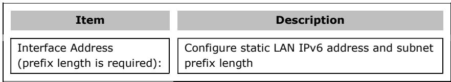
IPv6 LAN Applications
| Item | Description |
| Stateless | Use stateless configuration |
| Stateful | Use stateful configuration |
| Start interface ID: | Start of interface ID to be assigned to dhcpv6 client |
| End interface ID: | End of interface ID to be assigned to dhcpv6 client |
| Leased Time (hour): | Lease time for dhcpv6 client to use the assigned IP address |
| Item | Description |
| Enable RADVD | Enable use of router advertisement daemon |
| Enable ULA PrefixAdvertisement | Allow RADVD to advertise Unique Local Address Prefix |
| Randomly Generate | Use a Randomly Generated Prefix |
| Statically Configure Prefix | Specify the prefix to be used |
| Preferred Life Time (hour) | The preferred life time for this prefix |
| Valid Life Time (hour) | The valid life time for this prefix |
| Enable MLD Snooping | Enable/disable IPv6 multicast forward to LAN ports |
| Standard ModeBlocking Mode | In standard mode, IPv6 multicast traffic will flood to all bridge ports when no client subscribes to a multicast group even if MLD snooping is enabledIn blocking mode, IPv6 multicast data traffic will be blocked and not flood to all bridge ports when there are no client subscriptions to any multicast group |
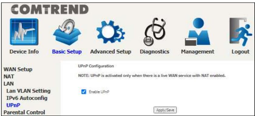
5.3.3 UPnP
Select the checkbox☑ provided and click Apply/Save to enable UPnP protocol.
5.4 Parental Control
This selection provides WAN access control functionality.
5.4.1 Time Restriction
This feature restricts access from a LAN device to an outside network through the device on selected days at certain times. Make sure to activate the Internet Time server synchronization as described in section 8.6 Internet Time, so that the scheduled times match your local time.
Clicking on the checkbox in the Enable field allows the user to select all / none entries for Enabling/Disabling.

COMTREND
Device Info

Basic Setup

Advanced Setup

Diagnostics

Management

Logout
Access Time Restriction -- A maximum 32 entries can be configured.
WAN Setup
NAT
LAN
Parental Control
Time Restriction
Url Filter


Click Add to display the following screen.

COMTREND
Device Info

Basic Setup

Advanced Setup

Diagnostics

Management

Logout
WAN Setup
NAT
LAN
Parental Control
Time Restriction
Url Filter
Home Networking
Wireless
WifiXtend2.0
AutoXtend
Access Time Restriction
This page adds time of day restriction to a special LAN device connected to the Router. The "Browser's MAC Address" automatically displays the MAC address of the LAN device where the browser is running. To restrict other LAN device, click the "Other MAC Address" button and enter the MAC address of the other LAN device. To find out, the MAC address of a Windows based PC, go to command window and type "pconfig/all".
User Name

Browser's HAC Address
Other MAC Address (xxxxxx)

Start Blocking Time (hh:mm)
End Blocking Time (hh:mm)

Apply!Save
See below for item descriptions. Click Apply/Save to add a time restriction.
```plaintext User Name: A user-defined label for this restriction.
Browser's MAC Address: MAC address of the PC running the browser.
Other MAC Address: MAC address of another LAN device.
Days of the Week: The days the restrictions apply.
Start Blocking Time: The time the restrictions start.
End Blocking Time: The time the restrictions end.
5.4.2 URL Filter
This screen allows for the creation of a filter rule for access rights to websites based on their URL address and port number.
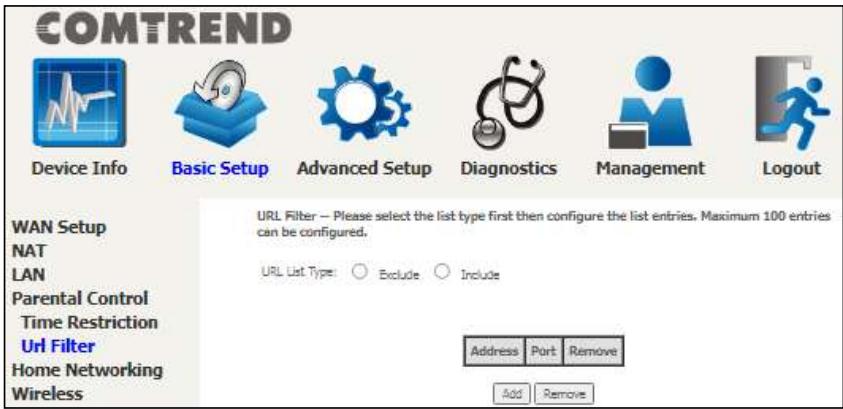
Select URL List Type: Exclude or Include.
Tick the Exclude radio button to deny access to the websites listed.
Tick the Include radio button to restrict access to only those listed websites.
Then click Add to display the following screen.
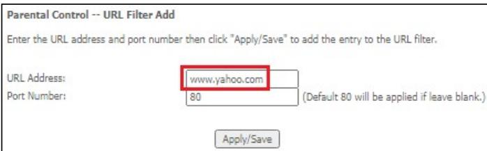
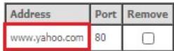
Enter the URL address and port number then click Apply/Save to add the entry to the URL filter. URL Addresses begin with "www", as shown in this example.
COMTREND
URL Filter -- Please select the list type first then configure the list entries. Maximum 100 entries can be configured.
URL List Types

Exclude

Add
Remove
A maximum of 100 entries can be added to the URL Filter list.
5.6 Home Networking
5.6.1 Print Server
This page allows you to enable or disable printer support.

Please reference Appendix E to see the procedure for enabling the Printer Server.
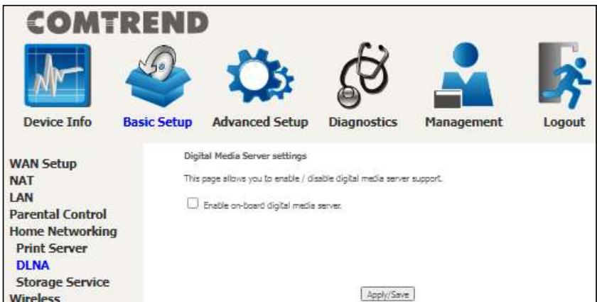
5.6.2 DLNA
Enabling DLNA allows users to share digital media, like pictures, music and video, to other LAN devices from the digital media server.
Insert the USB drive into the USB host port on the back of the router. Click Enable on-board digital media server, a dropdown list of directories found on the USB driver will be available for selection. Select media path from the dropdown list or manually modify the media library path and click Apply/Save to enable the DLNA media server.
5.6.3 Storage Service
The Storage service allows you to use Storage devices with modem to be more easily accessed.
5.6.3.1 Storage Device Info
This page also displays storage devices attached to the USB host.
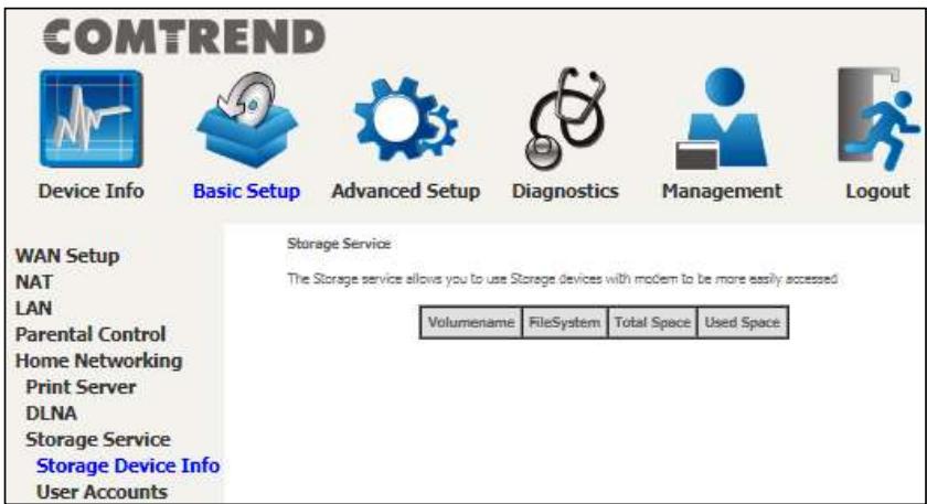
Display after storage device attached (for your reference).
| Volumename | FileSystem | Total Space | Used Space |
| disk1_1 | fat | 962 | 6 |
5.6.3.2 Storage User Accounts
Add a storage account to access the USB device for the samba access system.
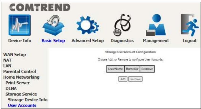
Click the Add button to display the following.(volumeName would be disk1_1 if only 1 USB has been plugged into the device.
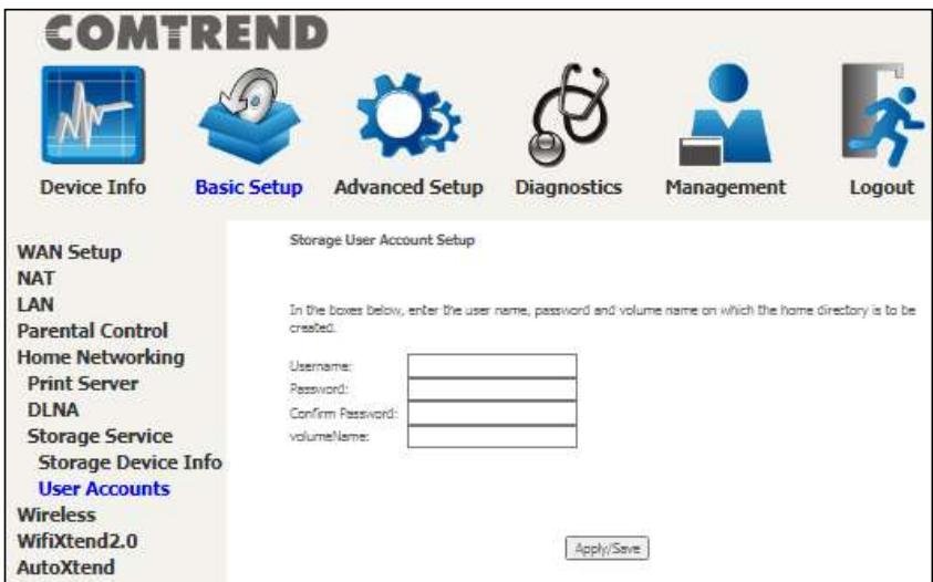
In the boxes provided, enter the user name, password and volume name on which the home directory is to be created. Then click the Apply/Save button.
COMTREND
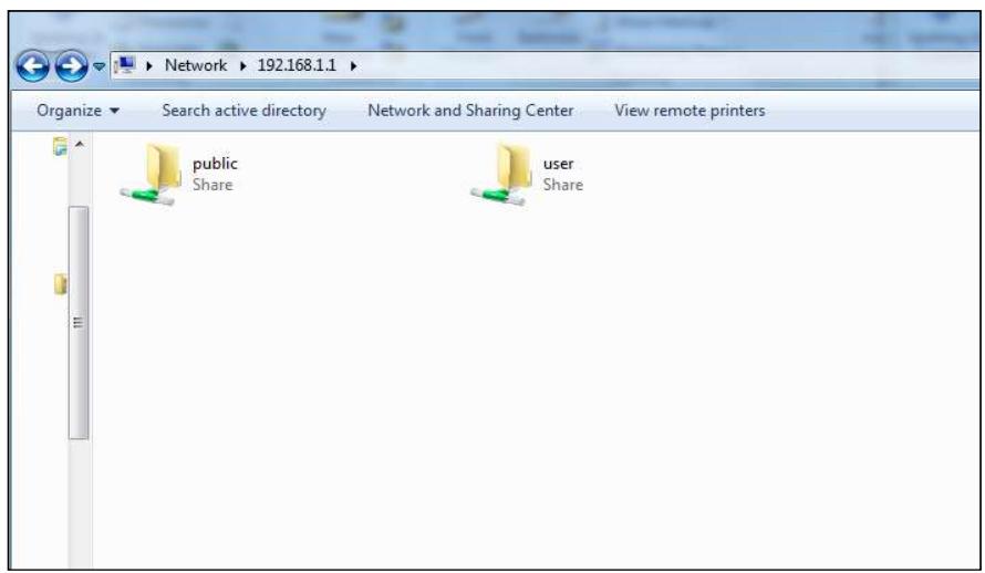
In any windows folder, enter the address \192.168.1.1 to access the samba folder created. A password prompt will show. Enter username password as configured.
Access \192.168.1.1 again (or refresh the screen), the user folder will now be available for access.
5.7 Wireless
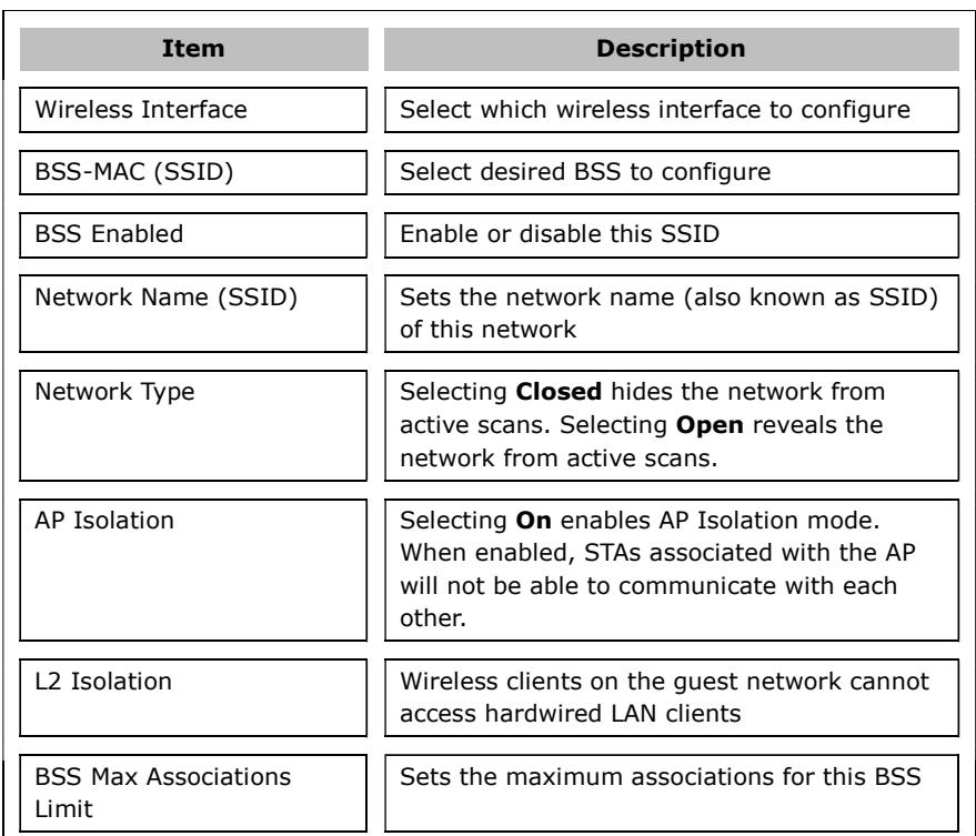
5.7.1 SSID
This page allows you to configure the Virtual interfaces for each Physical interface.
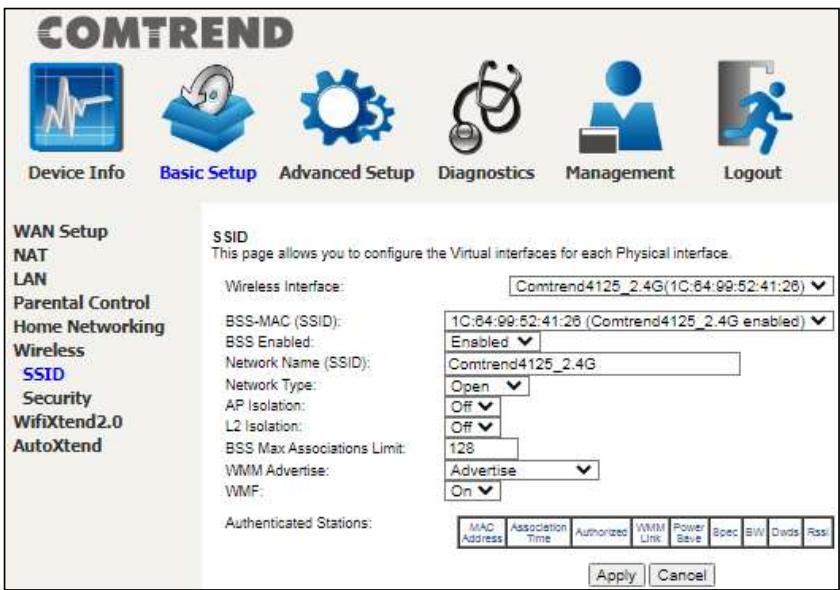
Click the Apply button to apply your changes. The settings shown above are described below.
COMTREND
WMM Advertise
When WMM is enabled for the radio, selecting On allows WMM to be advertised in beacons and probes for this BSS. Off disables advertisement of WMM in beacons and probes.
WMF
Choose On to enable Wireless Multicast Forwarding on this BSS. Off disables this feature.
MAC Address
Lists the MAC address of all the stations.
Association Time
Lists all the stations that are associated with the Access
Point, along with the amount of time since packets were transferred to and from each station. If a station is idle for too long, it is removed from this list.
Signal Strength
Wi-Fi connection signal strength icon
Authorized
Lists those devices with authorized access
WMM Link
Lists those devices that utilize WMM
Power Save
Lists those devices that utilize the Power Save Feature
Spec
Wi-Fi Spec
BW
Bandwidth
Dwds
Lists the devices that utilize Dynamic WDS
Rssi
Received Signal Strength Indicator
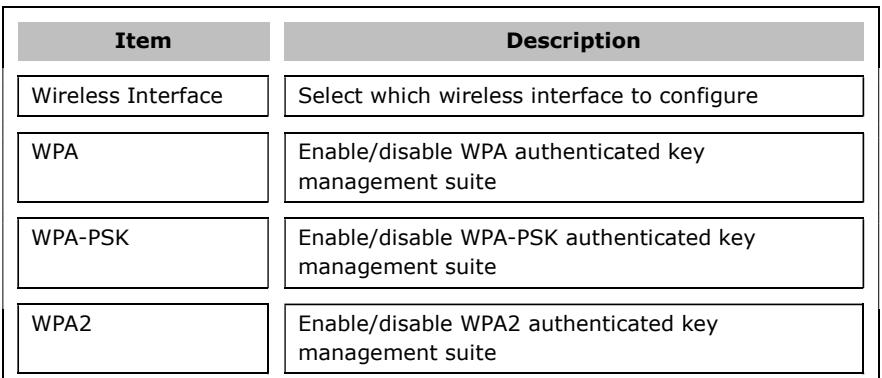
5.7.2 Security
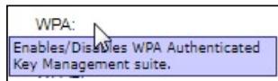
This page allows you to configure security for the wireless LAN interfaces.
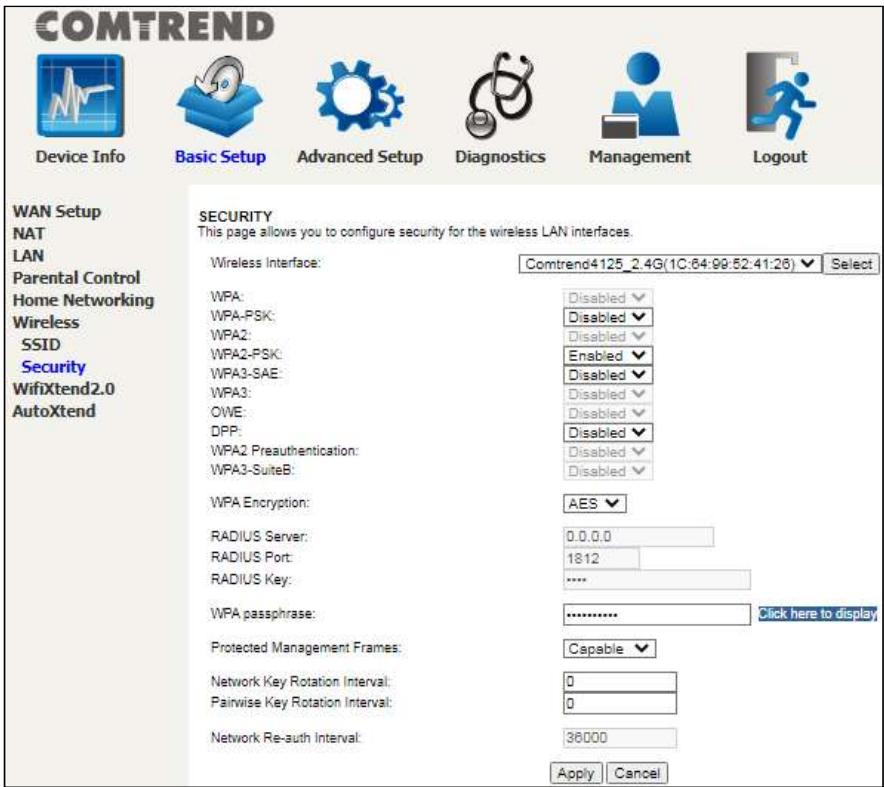
Click the Apply button to apply your changes. For information on each parameter, move the cursor over the parameter that you are interested in (as shown here).
COMTREND
WPA2-PSK
Enable/disable WPA2-PSK authenticated key management suite
WPA3-SAE
Enable/disable WPA3-SAE authenticated key management suite
WPA3
Enable/disable WPA3 authenticated key management suite
OWE
Enable/disable OWE authenticated key management suite
DPP
Enable/disable DPP authenticated key management suite
WPA2
Enable/disable WPA2 Preauthenticated key management suite
Preauthentication
Enable/disable WPA3-SuiteB key management suite
WPA3-SuiteB
Select the WPA encryption algorithm
WPA Encryption
Set the IP of the RADIUS (Remote Authentication Dial In User Service) to use for authentication and dynamic key derivation
RADIUS Server
RADIUS Port
Set the UDP port number of the RADIUS server. The port number is usually 1812 or 1645 and depends upon the server.
RADIUS Key
Set the shared secret for the RADIUS connection
WPA passphrase
Set the WPA passphrase
Protected Management Frames
Wi-Fi CERTIFIED WPA2 with Protected Management Frames provides a WPA2-level of protection for unicast and multicast management action frames.
Network Key Rotation Interval
Set the Network Key Rotation interval in seconds. Leave blank or set to zero to disable the rotation.
Pairwise Key Rotation Interval
Set the Pairwise Key Rotation interval in seconds. Leave blank or set to zero to disable the rotation.
Network Reauth Interval
Set the Network Key Re-authentication interval in seconds. Leave blank or set to zero to disable
periodic network re-authentication.
5.8 AutoXtend
AutoXtend is a function to construct and optimize a mesh-network. To select information to synchronize with all mesh-network nodes, please check the desired item and click the Apply/Save button.
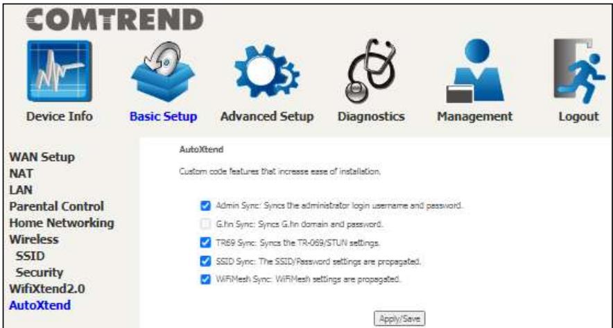
To enable the AutoXtend features, check the required checkboxes and click the Apply/Save button.
COMTREND
Chapter 6 Advanced Setup
You can reach this page by clicking on the following icon located at the top of the screen.

6.1 Security
For detailed descriptions, with examples, please consult Appendix A - Firewall.
6.1.1 IP Filtering
This screen sets filter rules that limit IP traffic (Outgoing/Incoming). Multiple filter rules can be set and each applies at least one limiting condition. For individual IP packets to pass the filter all conditions must be fulfilled.
NOTE: This function is not available when in WDS mode. Instead, MAC Filtering performs a similar function.
OUTGOING IP FILTER
By default, all outgoing IP traffic is allowed, but IP traffic can be blocked with filters.
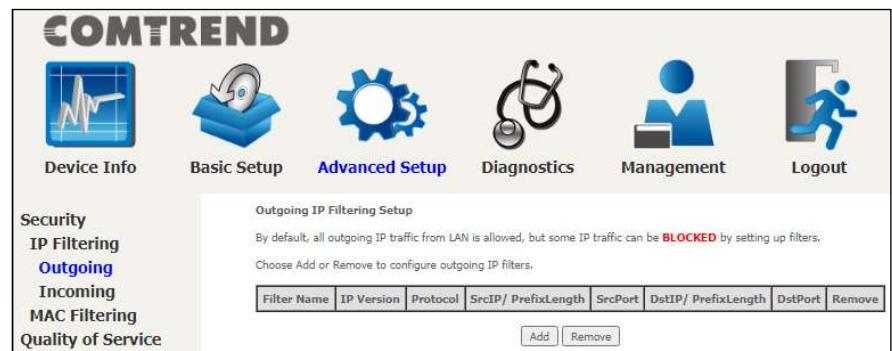
To add a filter (to block some outgoing IP traffic), click the Add button.
On the following screen, enter your filter criteria and then click Apply/Save.
COMTREND

Device Info

Basic Setup

Advanced Setup

Diagnostics

Management

Logout
Security
IP Filtering
Outgoing
Incoming
MAC Filtering
Quality of Service
Routing
DNS
DNS Proxy
Interface Grouping
IP Tunnel
IPSec
Add IP Filter - Outgoing
The screen allows you to create a filter rule to identify outgoing IP traffic by specifying a new filter name and at least one condition below. All of the specified conditions in this filter rule must be satisfied for the rule to take effect. Click 'Apply/Save' to save and activate the filter.
Filter Name:
IP Version:
Protocol:
Source IP address[/prefix length]:
Source Port (port or port:port):
Destination IP address[/prefix length]
Destination Port (port or port:port):
Apply/Save
Click the Apply/Save button to apply and save your changes.
Consult the table below for item descriptions.
Item
Filter Name
IP Version
Protocol
Source IP address
Source Port (port or port:port)
Destination IP address
Destination Port (port or port:port)
Description
The filter rule label (user defined)
Select from the drop down menu
Set the traffic type (TCP, TCP/UDP, UDP, or ICMP) that the rule will apply to
Enter source IP address for the IP filter
Enter source port number or range for the IP filter
Enter destination IP address for the IP filter
Enter destination port number or range for the IP filter
INCOMING IP FILTER
By default, all incoming IP traffic is blocked, but IP traffic can be allowed with filters.
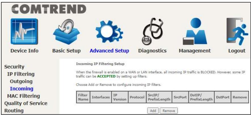
To add a filter (to allow incoming IP traffic), click the Add button.
On the following screen, enter your filter criteria and then click Apply/Save.
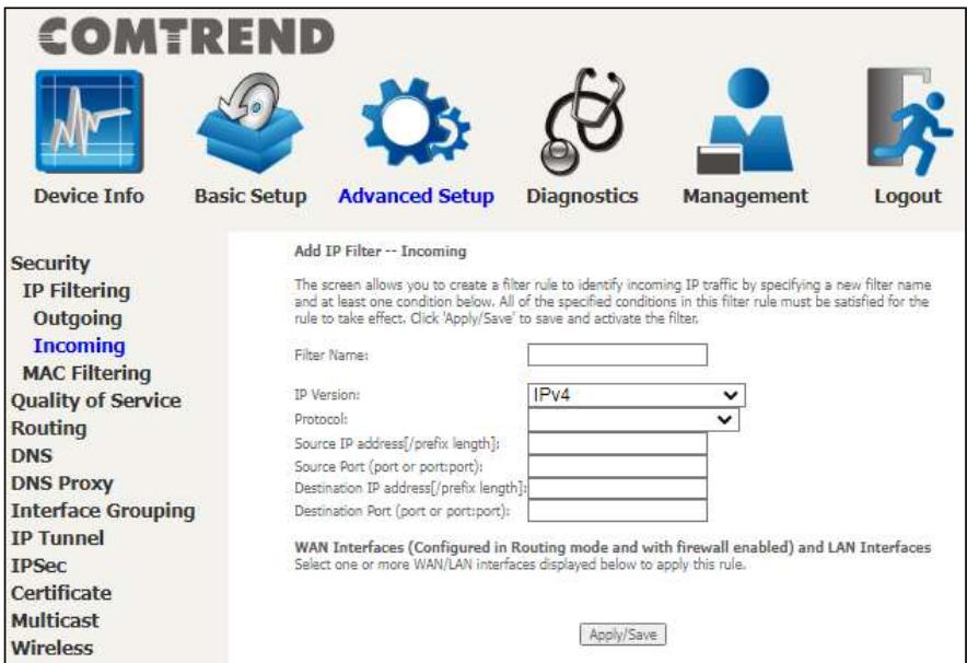
Consult the table below for item descriptions.
COMTREND
| Item | Description |
| Filter Name | The filter rule label (user defined) |
| IP Version | Select from the drop down menu |
| Protocol | Set the traffic type (TCP, TCP/UDP, UDP, or ICMP) that the rule will apply to |
| Source IP address | Enter source IP address for the IP filter |
| Source Port (port or port:port) | Enter source port number or range for the IP filter |
| Destination IP address | Enter destination IP address for the IP filter |
| Destination Port (port or port:port) | Enter destination port number or range for the IP filter |
At the bottom of this screen, select the WAN and LAN Interfaces to which the filter rule will apply. You may select all or just a subset. WAN interfaces in WDS mode or without firewall enabled are not available.
6.1.2 MAC Filtering
NOTE: This option is only available in WDS mode. Other modes use IP Filtering to perform a similar function.
Each network device has a unique 48-bit MAC address. This can be used to filter (block or forward) packets based on the originating device. MAC filtering policy and rules for the PRT-6351 can be set according to the following procedure.
The MAC Filtering Global Policy is defined as follows. FORWARDED means that all MAC layer frames will be FORWARDDED except those matching the MAC filter rules. BLOCKED means that all MAC layer frames will be BLOCKED except those matching the MAC filter rules. The default MAC Filtering Global policy is FORWARDDED. It can be changed by clicking the Change Policy button.
COMTREND

Device Info

Basic Setup

Advanced Setup

Diagnostics

Management

Logout
Security
IP Filtering
MAC Filtering
Quality of Service
Routing
DNS
DNS Proxy
Interface Grouping
IP Tunnel
IPSec
Certificate
Multicast
Wireless
WifiXtend2.0
AutoXtend
MAC Filtering Setup
MAC Filtering is only effective on WAN services configured in Bridge mode. FORWARDED means that all MAC layer frames will be FORWARDED except those matching with any of the specified rules in the following table. BLOCKED means that all MAC layer frames will be BLOCKED except those matching with any of the specified rules in the following table.
MAC Filtering Policy For Each Interface:
WARNING: Changing from one policy to another of an interface will cause all defined rules for that interface to be REMOVED AUTOMATICALLY! You will need to create new rules for the new policy.
| Interface | Policy | Change |
| eth0.1 | FORWARD | □ |
| Change Policy |
Choose Add or Remove to configure MAC filtering rules.


Choose Add or Remove to configure MAC filtering rules. The following screen will appear when you click Add. Create a filter to identify the MAC layer frames by specifying at least one condition below. If multiple conditions are specified, all of them must be met.
COMTREND

Device Info

Basic Setup

Advanced Setup

Diagnostics

Management

Logout
Security
IP Filtering
MAC Filtering
Quality of Service
Routing
DNS
DNS Proxy
Interface Grouping
IP Tunnel
IPSec
Certificate
Multicast
Add MAC Filter
Create a filter to identify the MAC layer frames by specifying at least one condition below. If
multiple conditions are specified, all of them take effect. Click "Apply" to save and activate the filter,
LAN<=WAN
WAN Interfaces (Configured in Bridge mode only)
eth0.1/eth0.1
Save/Apply
Click Save/Apply to save and activate the filter rule.
Consult the table below for detailed item descriptions.
Item
Protocol Type
Description
Select from the drop down menu the protocol (PPPoE, IPv4, IPv6, AppleTalk, IPX, NetBEUI, IGMP) that will apply to this rule.
Destination MAC
Address
Defines the destination MAC address
Source MAC Address
Frame Direction
Defines the source MAC address
WAN Interfaces
Select the incoming/outgoing packet interface
Applies the filter to the selected bridge interface
6.2 Quality of Service (QoS)
NOTE: QoS must be enabled in at least one PVC to display this option. (See Appendix F - Connection Setup for detailed PVC setup instructions).
To Enable QoS tick the checkbox × and select a Default DSCP Mark.
Click Apply/Save to activate QoS.
COMTREND

Device Info

Basic Setup

Advanced Setup

Diagnostics

Management

Logout
Security
Quality of Service
QoS Queue
QoS Classification
QoS Port Shaping
Routing
DNS
DNS Proxy
Interface Grouping
IP Tunnel
IPSec
Certificate
Multicast
QoS - Queue Management Configuration
If Enable QoS checkbox is selected, choose a default DSCP mark to automatically mark incoming traffic without reference to a particular classifier. Click 'Apply/Save' button to save it.
Note: If Enable Qos checkbox is not selected, all QoS will be disabled for all interfaces.
Note: The default DSCP mark is used to mark all egress packets that do not match any classification rules.

Enable QoS
Apply/Save
QoS and DSCP Mark are defined as follows:
Quality of Service (QoS): This provides different priority to different users or data flows, or guarantees a certain level of performance to a data flow in accordance with requests from Queue Prioritization.

Enable QoS
Select Default DSCP Mark
No Change(-1)
Default Differentiated Services Code Point (DSCP) Mark: This specifies the per hop behavior for a given flow of packets in the Internet Protocol (IP) header that do not match any other QoS rule.
COMTREND
6.2.1 QoS Queue
6.2.1.1 QoS Queue Configuration
Configure queues with different priorities to be used for QoS setup.
In ATM mode, a maximum of 16 queues can be configured.
In PTM mode, a maximum of 8 queues can be configured.
For each Ethernet interface, a maximum of 8 queues can be configured.
For each Ethernet WAN interface, a maximum of 8 queues can be configured.
(Pleasesee the screen on the following page).
COMTREND

Device Info

Basic Setup

Advanced Setup

Diagnostics

Management

Logout
Security
Quality of Service
QoS Queue
Queue Configuration
Wlan Queue
Qos Classification Qos Port Shaping
Routing
DNS
DNS Proxy
Interface Grouping
IP Tunnel
IPSec
Certificate
Multicast
Wireless
WifiXtend2.0
AutoXtend
QoS Queue Setup
For each Ethernet interface, maximum 8 queues can be configured.
For each Ethernet WAN interface, maximum 8 queues can be configured.
To remove puses, check their remove-check boxes, than click the Remove button.
The Enable button will scan through every queues in the table. Quees with enable-checkbox checked will be enabled. Quees
with enable-checkbox un-checked will be disabled, The enable-checkbox also shows status of the survey after more relaxed.
| Name | Key | Interface | Qid | Prec/Alg/Wght | DropAlg/ LoMin/LoMax/HiMin/HiMax | TcpAck | Enable | Remove |
| LAN Q8 | 193 | eth1 | 8 | 1/SP | DT | √ | □ | |
| LAN Q7 | 194 | eth1 | 7 | 2/SP | DT | √ | □ | |
| LAN Q6 | 195 | eth1 | 6 | 3/SP | DT | √ | □ | |
| LAN Q5 | 196 | eth1 | 5 | 4/SP | DT | √ | □ | |
| LAN Q4 | 197 | eth1 | 4 | 5/SP | DT | √ | □ | |
| LAN Q3 | 198 | eth1 | 3 | 6/SP | DT | √ | □ | |
| LAN Q2 | 199 | eth1 | 2 | 7/SP | DT | √ | □ | |
| LAN Q1 | 200 | eth1 | 1 | 8/SP | DT | √ | □ | |
| LAN Q8 | 201 | eth2 | 8 | 1/SP | DT | √ | □ | |
| LAN Q7 | 202 | eth2 | 7 | 2/SP | DT | √ | □ | |
| LAN Q6 | 203 | eth2 | 6 | 3/SP | DT | √ | □ | |
| LAN Q5 | 204 | eth2 | 5 | 4/SP | DT | √ | □ | |
| LAN Q4 | 205 | eth2 | 4 | 5/SP | DT | √ | □ | |
| LAN Q3 | 206 | eth2 | 3 | 6/SP | DT | √ | □ | |
| LAN Q2 | 207 | eth2 | 2 | 7/SP | DT | √ | □ | |
| LAN Q1 | 208 | eth2 | 1 | 8/SP | DT | √ | □ | |
| LAN Q8 | 209 | eth3 | 8 | 1/SP | DT | √ | □ | |
| LAN Q7 | 210 | eth3 | 7 | 2/SP | DT | √ | □ | |
| LAN Q6 | 211 | eth3 | 6 | 3/SP | DT | √ | □ | |
| LAN Q5 | 212 | eth3 | 5 | 4/SP | DT | √ | □ | |
| LAN Q4 | 213 | eth3 | 4 | 5/SP | DT | √ | □ | |
| LAN Q3 | 214 | eth3 | 3 | 6/SP | DT | √ | □ | |
| LAN Q2 | 215 | eth3 | 2 | 7/SP | DT | √ | □ | |
| LAN Q1 | 216 | eth3 | 1 | 8/SP | DT | √ | □ | |
| LAN Q8 | 217 | eth4 | 8 | 1/SP | DT | √ | □ | |
| LAN Q7 | 218 | eth4 | 7 | 2/SP | DT | √ | □ | |
| LAN Q6 | 219 | eth4 | 6 | 3/SP | DT | √ | □ | |
| LAN Q5 | 220 | eth4 | 5 | 4/SP | DT | √ | □ | |
| LAN Q4 | 221 | eth4 | 4 | 5/SP | DT | √ | □ | |
| LAN Q3 | 222 | eth4 | 3 | 6/SP | DT | √ | □ | |
| LAN Q2 | 223 | eth4 | 2 | 7/SP | DT | √ | □ | |
| LAN Q1 | 224 | eth4 | 1 | 8/SP | DT | √ | □ | |
| VAN Q8 | 225 | eth0 | 8 | 1/SP | DT | √ | □ | |
| VAN Q7 | 226 | eth0 | 7 | 2/SP | DT | √ | □ | |
| VAN Q6 | 227 | eth0 | 6 | 3/SP | DT | √ | □ | |
| VAN Q5 | 228 | eth0 | 5 | 4/SP | DT | √ | □ | |
| VAN Q4 | 229 | eth0 | 4 | 5/SP | DT | √ | □ | |
| VAN Q3 | 230 | eth0 | 3 | 6/SP | DT | √ | □ | |
| VAN Q2 | 231 | eth0 | 2 | 7/SP | DT | V | √ | □ |
| VAN Q1 | 232 | eth0 | 1 | 8/SP | DT | √ | □ |
Add Enable Remove
COMTREND
To remove queues, check their remove-checkboxes (for user created queues), then click the Remove button.
The Enable button will scan through every queue in the table. Queues with the enable-checkbox checked will be enabled. Queues with the enable-checkbox unchecked will be disabled.
The enable-checkbox also shows status of the queue after page reload.
Note that if WMM function is disabled in the Wireless Page, queues related to wireless will not take effect. This function follows the Differentiated Services rule of IP QoS.
Enable and assign an interface and precedence on the next screen. Click Apply/Save on this screen to activate it.
To add a queue, click the Add button to display the following screen.
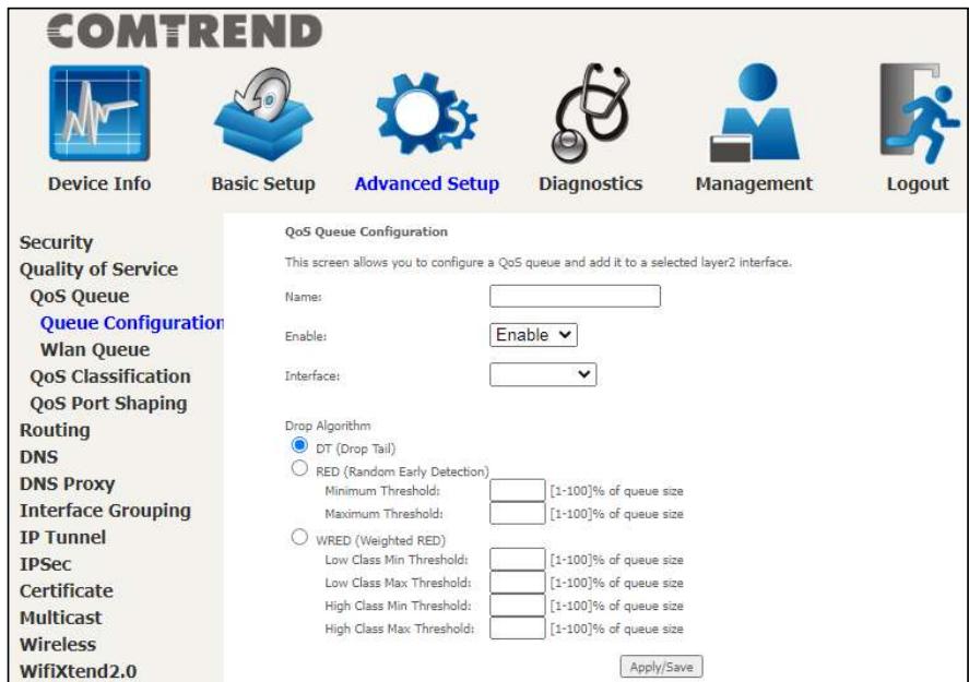
Name: Identifier for this Queue entry.
Enable: Enable/Disable the Queue entry.
Interface: Assign the entry to a specific network interface (QoS enabled).
Drop Algorithm: Select the algorithm to be used to ensure that the QoS rule is enforced if the traffic exceeds the configured limit.
Drop Tail: Packets are sent in first come first serve fashion, the tailing traffic would be dropped if they exceed the handling limit.
Random Early Detection: Packets are monitored by configured queue threshold and serving proportion.
WRED: Weighted RED, the assigned monitoring queue would be given different priority and threshold to ensure various priority queues would be served fairly. After selecting an Interface the following will be displayed.
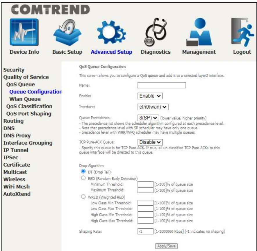
The precedence list shows the scheduler algorithm for each precedence level. Queues of equal precedence will be scheduled based on the algorithm. Queues of unequal precedence will be scheduled based on SP.
Shaping Rate: Specify a shaping rate limit to the defined queue.
Click Apply/Save to apply and save the settings.
6.2.1.2 Wlan Queue
Displays the list of available wireless queues for WMM and wireless data transmit priority.

COMTREND
Device Info

Basic Setup

Advanced Setup

Diagnostics

Management

Logout
Security
Quality of Service
QoS Queue
Queue Configuration
Wlan Queue
QoS Classification
QoS Port Shaping
Routing
DNS
DNS Proxy
Interface Grouping
IP Tunnel
IPSec
Certificate
Multicast
Wireless
WifiXtend2.0
AutoXtend
QoS Wlan Queue Setup
Note: If WMM function is disabled in Wireless Page, queues related to wireless will not take effects.
| Name | Key | Interface | Qid | Prec/Alg/Wght | Enable |
| WMM Voice Priority | 1 | wID | 8 | 1/SP | Enabled |
| WMM Voice Priority | 2 | wID | 7 | 2/SP | Enabled |
| WMM Video Priority | 3 | wID | 6 | 3/SP | Enabled |
| WMM Video Priority | 4 | wID | 5 | 4/SP | Enabled |
| WMM Best Effort | 5 | wID | 4 | 5/SP | Enabled |
| WMM Background | 6 | wID | 3 | 6/SP | Enabled |
| WMM Background | 7 | wID | 2 | 7/SP | Enabled |
| WMM Best Effort | 8 | wID | 1 | 8/SP | Enabled |
| WMM Voice Priority | 65 | wI1 | 8 | 1/SP | Enabled |
| WMM Voice Priority | 66 | wI1 | 7 | 2/SP | Enabled |
| WMM Video Priority | 67 | wI1 | 6 | 3/SP | Enabled |
| WMM Video Priority | 68 | wI1 | 5 | 4/SP | Enabled |
| WMM Best Effort | 69 | wI1 | 4 | 5/SP | Enabled |
| WMM Background | 70 | wI1 | 3 | 6/SP | Enabled |
| WMM Background | 71 | wI1 | 2 | 7/SP | Enabled |
| WMM Best Effort | 72 | wI1 | 1 | 8/SP | Enabled |
| WMM Voice Priority | 129 | wI2 | 8 | 1/SP | Enabled |
| WMM Voice Priority | 130 | wI2 | 7 | 2/SP | Enabled |
| WMM Video Priority | 131 | wI2 | 6 | 3/SP | Enabled |
| WMM Video Priority | 132 | wI2 | 5 | 4/SP | Enabled |
| WMM Best Effort | 133 | wI2 | 4 | 5/SP | Enabled |
| WMM Background | 134 | wI2 | 3 | 6/SP | Enabled |
| WMM Background | 135 | wI2 | 2 | 7/SP | Enabled |
| WMM Best Effort | 136 | wI2 | 1 | 8/SP | Enabled |
6.2.2 QoS Classification
The network traffic classes are listed in the following table.
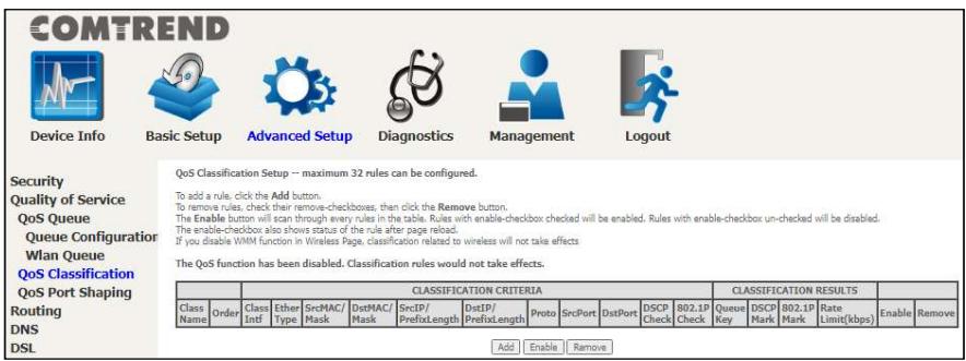
Click Add to configure a network traffic class rule and Enable to activate it. To delete an entry from the list, click Remove.
This screen creates a traffic class rule to classify the upstream traffic, assign queuing priority and optionally overwrite the IP header DSCP byte. A rule consists of a class name and at least one logical condition. All the conditions specified in the rule must be satisfied for it to take effect.
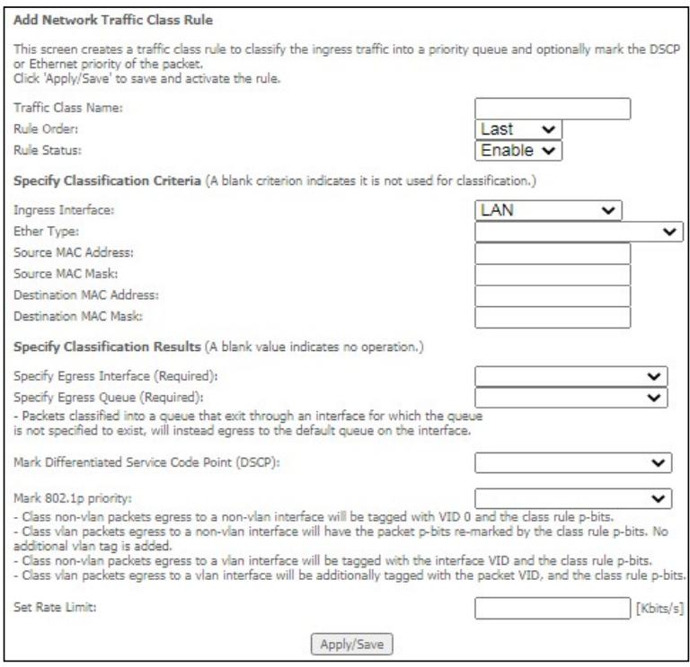
Click Apply/Save to save and activate the rule.
Consult the table below for detailed item descriptions.
| Item | Description |
| Traffic Class Name | Enter a name for the traffic class. |
| Rule Order | Last is the only option. |
| Rule Status | Disable or enable the rule. |
| Classification Criteria | |
| Ingress Interface | Select an interface: (i.e. LAN, WAN, local, ETH1, ETH2, ETH3, w10) |
| Ether Type | Set the Ethernet type (e.g. IP, ARP, IPv6). |
| Source MAC Address | A packet belongs to SET-1, if a binary-AND of its source MAC address with the Source MAC Mask is equal to the binary-AND of the Source MAC Mask and this field. |
| Source MAC Mask | This is the mask used to decide how many bits are checked in Source MAC Address. |
| Destination MAC Address | A packet belongs to SET-1 then the result that the Destination MAC Address of its header binary-AND to the Destination MAC Mask must equal to the result that this field binary-AND to the Destination MAC Mask. |
| Destination MAC Mask | This is the mask used to decide how many bits are checked in the Destination MAC Address. |
| Classification Results | |
| Specify Egress Interface | Choose the egress interface from the available list. |
| Specify Egress Queue | Choose the egress queue from the list of available for the specified egress interface. |
| Mark Differentiated Service Code Point | The selected Code Point gives the corresponding priority to packets that satisfy the rule. |
| Mark 802.1p Priority | Select between 0-7. - Class non-vlan packets egress to a non-vlan interface will be tagged with VID 0 and the class rule p-bits. |
COMTREND
| - Class vlan packets egress to a non-vlan interface will have the packet p-bits re-marked by the class rule p-bits. No additional vlan tag is added. - Class non-vlan packets egress to a vlan interface will be tagged with the interface VID and the class rule p-bits. - Class vlan packets egress to a vlan interface will be additionally tagged with the packet VID, and the class rule p-bits. | |
| Set Rate Limit | The data transmission rate limit in kbps. |
6.2.3 QoS Port Shaping
QoS port shaping supports traffic shaping of the Ethernet interface. Input the shaping rate and burst size to enforce QoS rule on each interface. If "Shaping Rate" is set to "-1", it means no shaping and "Burst Size" will be ignored.
COMTREND

Device Info

Basic Setup

Advanced Setup

Diagnostics

Management

Logout
Security
Quality of Service
QoS Queue
Queue Configuration
Wlan Queue
QoS Classification
QoS Port Shaping
Routing
DNS
DNS Proxy
Interface Grouping
IP Tunnel
IPSec
Certificate
Multicast
Wireless
QoS Part Shaping Setup
QoS port shaping supports traffic shaping of Ethernet interface.
If "Shaping Rate" is set to "-1", it means no shaping and "Burst Size" will be ignored.
| Interface | Type | Shaping Rate (Mbps) | Burst Size (bytes) | Enable |
| eth0 | WAN | -1 | 0 | □ |
| eth1 | LAN | -1 | 0 | □ |
| eth2 | LAN | -1 | 0 | □ |
| eth3 | LAN | -1 | 0 | □ |
| eth4 | LAN | -1 | 0 | □ |
Apply/Save
Click Apply/Save to apply and save the settings.
6.3 Routing
The following routing functions are accessed from this menu: Default Gateway, Static Route, Policy Routing and RIP.
NOTE: In WDS mode, the RIP menu option is hidden while the other menu options are shown but ineffective.
6.3.1 Default Gateway
The default gateway interface list can have multiple WAN interfaces served as system default gateways but only one will be used according to the priority with the first being the highest and the last one the lowest priority if the WAN interface is connected. Priority order can be changed by removing all and adding them back in again.
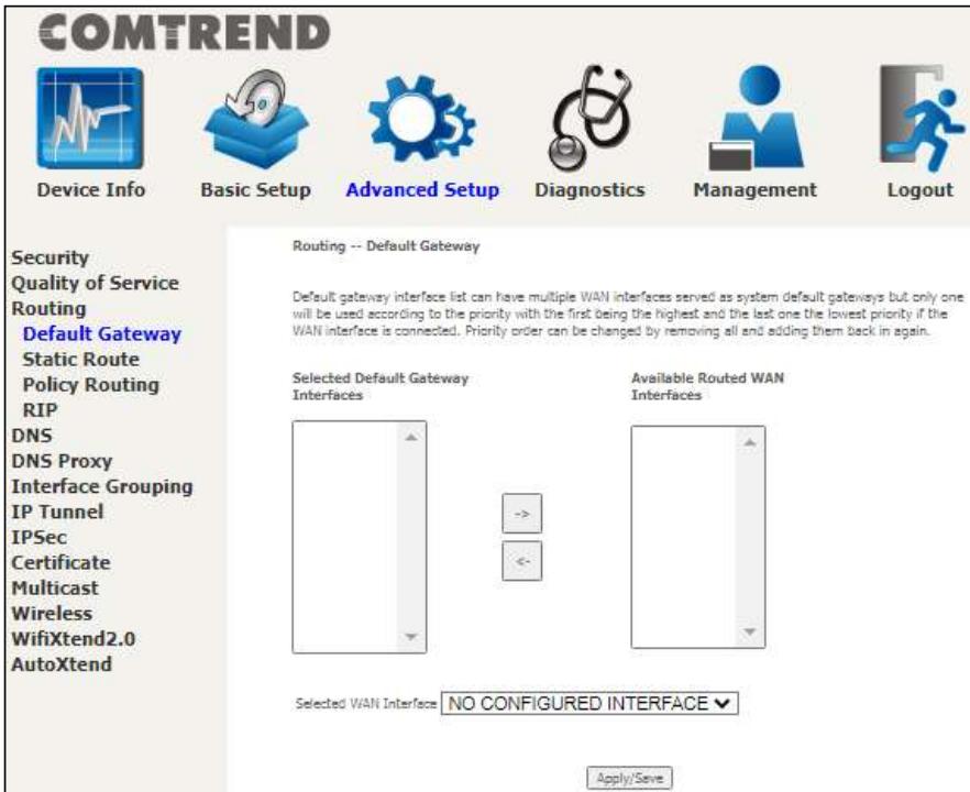
Click Apply/Save to apply and save the settings.
6.3.2 Static Route
This option allows for the configuration of static routes by destination IP. Click Add to create a static route or click Remove to delete a static route.
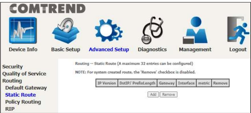
After clicking Add the following will display.
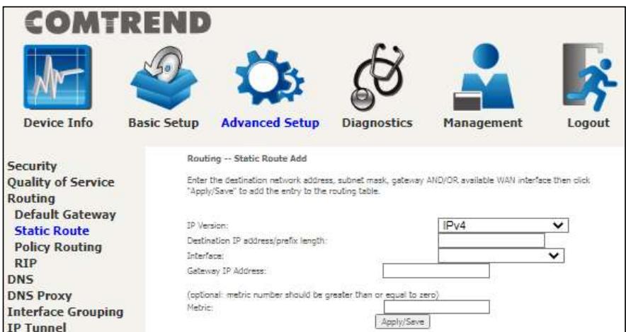
- IP Version: Select the IP version to be IPv4 or IPv6.
- Destination IP address-prefix length: Enter the destination IP address.
- Interface: Select the proper interface for the rule.
- Gateway IP Address: The next-hop IP address.
Metric: The metric value of routing.
After completing the settings, click Apply/Save to add the entry to the routing table.
6.3.3 Policy Routing
This option allows for the configuration of static routes by policy.
Click Add to create a routing policy or Remove to delete one.
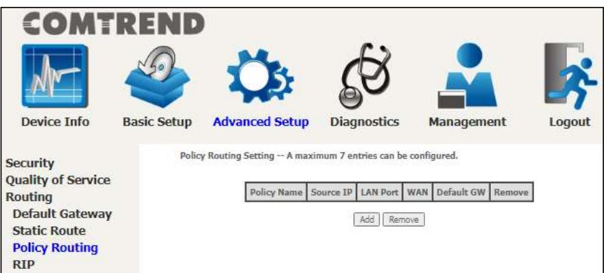
On the following screen, complete the form and click Apply/Save to create a policy.
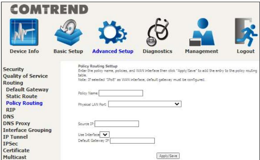
Consult the table below for detailed item descriptions.
COMTREND
| Item | Description |
| Policy Name | Name of the route policy |
| Physical LAN Port | Specify the port to use this route policy |
| Source IP | IP Address to be routed |
| Use Interface | Interface that traffic will be directed to |
| Default Gateway IP | IP Address of the default gateway |
6.3.4 RIP
To activate RIP, configure the RIP version/operation mode and select the Enabled checkbox for at least one WAN interface before clicking Apply/Save.
COMTREND
COMTREND

Device Info

Basic Setup

Advanced Setup

Diagnostics

Management

Logout
Security
Quality of Service
Routing
Default Gateway
Static Route
Policy Routing
RIP
DNS
DNS Proxy
Interface Grouping
Routing--RIPConfiguration
NOTE: If selected interface has NAT enabled, only Passive mode is allowed.
To activate RIP for the WAN Interface, select the desired RIP version and operation and place a check in the 'Enabled' checkbox. To stop RIP on the WAN Interface, uncheck the 'Enabled' checkbox. Click the 'Apply/Save' button to start/stop RIP and save the configuration.

VIAN Interface not exist for RIP.
6.4 DNS
6.4.1 DNS Server
Select DNS Server Interface from available WAN interfaces OR enter static DNS server IP addresses for the system. In ATM mode, if only a single PVC with IPOA or static IPOE protocol is configured, Static DNS server IP addresses must be entered.
DNS Server Interfaces can have multiple WAN interfaces served as system DNS servers but only one will be used according to the priority with the first being the highest and the last one the lowest priority if the WAN interface is connected. Priority order can be changed by removing all and adding them back in again.
COMTREND

Device Info

Basic Setup

Advanced Setup

Diagnostics

Management

Logout
Security
Quality of Service
Routing
DNS
DNS Server
Dynamic DNS
DNS Entries
DNS Proxy
Interface Grouping
IP Tunnel
IPSec
Certificate
Multicast
Wireless
WifiXtend2.0
AutoXtend
DNS Server Configuration
Select DNS Server Interface from available WAN Interfaces OR enter static DNS server IP addresses for the system. If only a single WAN with static IPv6 protocol is configured, Static DNS server IP addresses must be entered.
DNS Server Interfaces can have multiple WAN interfaces served as system dns servers but only one will be used according to the priority with the first being the highest and the last one the lowest priority if the WAN interface is connected. Priority order can be changed by removing all and adding them back in again.

Select DNS Server Interface from available WAN interfaces:
Selected DNS Server Interfaces
Available WAN Interfaces


Use the following Static DNS IP address:
Primary DNS server:
Secondary DNS server


Obtain IPv6 DNS info from a WAN interface
WAN Interface selected
NO CONFIGURED INTE

Use the following Static IPv6 DNS address:
Primary IPv6 DNS server:
Secondary IPv6 DNS server

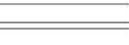
Apply/Save
Click Apply/Save to save the new configuration.
6.4.2 Dynamic DNS
The Dynamic DNS service allows you to map a dynamic IP address to a static hostname in any of many domains, allowing the PRT-6351 to be more easily accessed from various locations on the Internet.
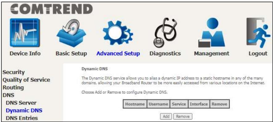
To add a dynamic DNS service, click Add. The following screen will display.
Click Apply/Save to save your settings.
Consult the table below for item descriptions.

COMTREND
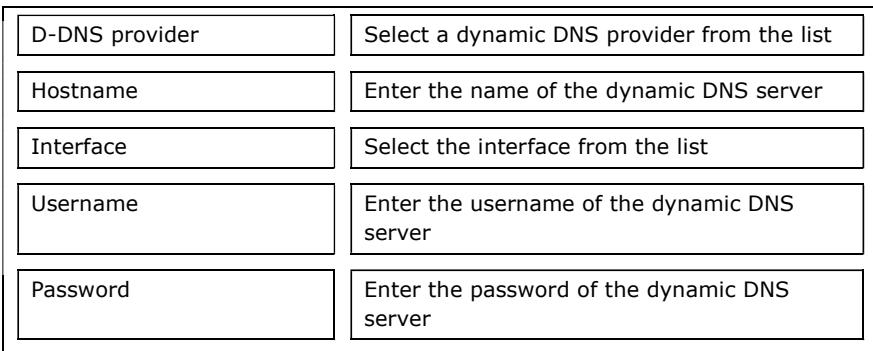
6.4.3 DNS Entries
The DNS Entry page allows you to add domain name and IP address pairs desired to be resolved by the DSL router.
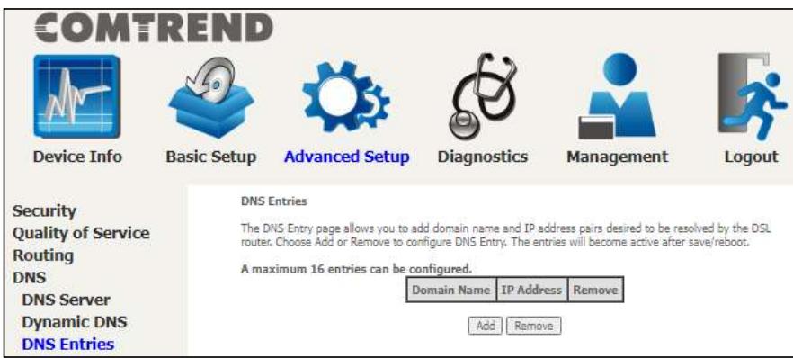
Choose Add or Remove to configure a DNS Entry. The entries will become active after save/reboot.
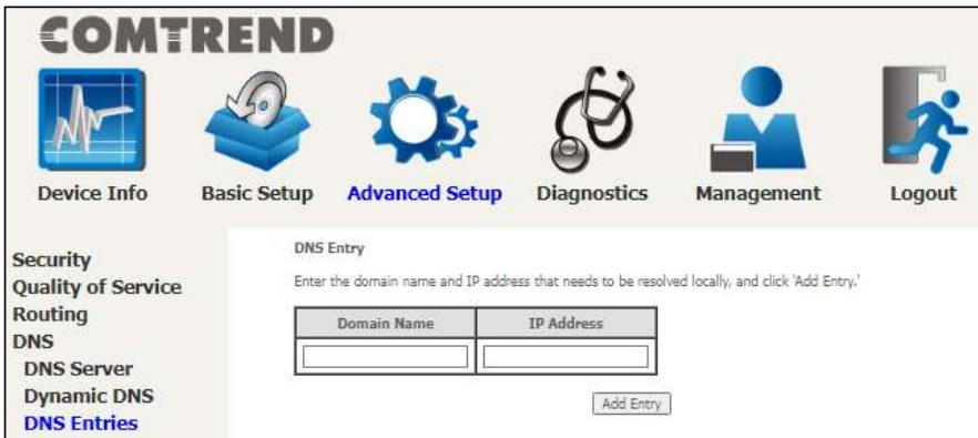
Enter the domain name and IP address that needs to be resolved locally, and click the Add Entry button.
6.5 DNS Proxy
DNS proxy receives DNS queries and forwards DNS queries to the Internet. After the CPE gets answers from the DNS server, it replies to the LAN clients. Configure DNS proxy with the default setting, when the PC gets an IP via DHCP, the domain name, Home, will be added to PC's DNS Suffix Search List, and the PC can access route with "Comtrend.Home".
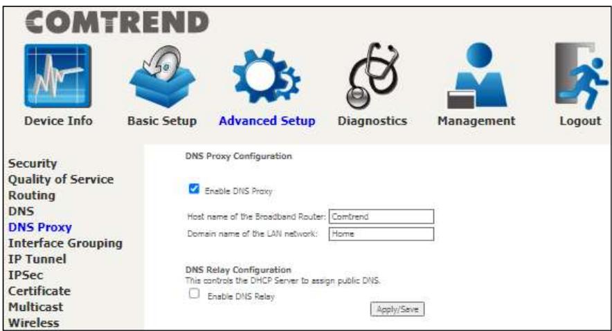
6.8 Interface Grouping
Interface Grouping supports multiple ports to PVC and bridging groups. Each group performs as an independent network. To use this feature, you must create mapping groups with appropriate LAN and WAN interfaces using the Add button. The Remove button removes mapping groups, returning the ungrouped interfaces to the Default group. Only the default group has an IP interface.

COMTREND
Device Info

Basic Setup

Advanced Setup

Diagnostics

Management

Logout
Security
Quality of Service
Routing
DNS
DNS Proxy
Interface Grouping
IP Tunnel
IPSec
Certificate
Multicast
Wireless
WifiXtend2.0
AutoXtend
Interface Grouping -- A maximum 16 entries can be configured
Interface Grouping supports multiple ports to WAN and bridging groups. Each group will perform as an independent network. To support this feature, you must create mapping groups with appropriate LAN and WAN interfaces using the Add button. The Remove button will remove the grouping and add the ungrouped interfaces to the Default group. Only the default group has IP interface.
| Group Name | Remove | WAN Interface | LAN Interfaces | DHCP Vendor IDs |
| Default | eth0.1 | ETH1 | ||
| ETH2 | ||||
| ETH3 | ||||
| ETH4 | ||||
| Comtrend4125_2.4G | ||||
| Comtrend4125_6G | ||||
| Comtrend4125_5G |

To add an Interface Group, click the Add button. The following screen will appear. It lists the available and grouped interfaces. Follow the instructions shown onscreen.
COMTREND

Device Info

Basic Setup

Advanced Setup

Diagnostics

Management

Logout
Security
Quality of Service
Routing
DNS
DNS Proxy
Interface Grouping
IP Tunnel
IPSec
Certificate
Multicast
Wireless
WifiXtend2.0
AutoXtend
Interface grouping Configuration
To create a new interface group:
-
Enter the Group name and the group name must be unique and select either 2. (dynamic) or 3. (static) below.
-
If you like to automatically add LAN clients to a WAN Interface in the new group add the DHCP vendor ID string. By configuring a DHCP vendor ID string any DHCP client request with the specified vendor ID (DHCP option 60) will be denied an IP address from the local DHCP server.
-
Select interfaces from the available interface list and add it to the grouped interface list using the arrow buttons to create the required mapping of the ports. Note that these clients may obtain public IP addresses
-
Click Apply/Save button to make the changes effective immediately
IMPORTANT If a vendor ID is configured for a specific client device, please REBOOT the client device attached to the modern to allow it to obtain an appropriate IP address.
Group Name:
1 + u7 = 70%
12x - 1 > 0
一
-
m : x = 1 或 3x + 4y + 1 = 0
m : x = 1 或 3x + 4y + 1 = 0
一
m : x = 1 或 3x + 4y + 1 = 0
12x - 1 > 0
m : x = 1 或 3x + 4y + 1 = 0
no
m - 1 0 ;
m - 1 0 ;
1 + u1 - 1 = ( 1 + u) u1 < 1 = u
1 + u7 = 70%

Grouped LAN Interfaces

Available LAN Interfaces
Automatically Add Clients With the following DHCP Vendor IDs

Automatically Add Clients With Following DHCP Vendor IDs:
Add support to automatically map LAN interfaces to PVC's using DHCP vendor ID (option 60). The local DHCP server will decline and send the requests to a remote DHCP server by mapping the appropriate LAN interface. This will be turned on when Interface Grouping is enabled.
For example, imagine there are 4 PVCs (0/33, 0/36, 0/37, 0/38). VPI/VCI=0/33 is for PPPoE while the other PVCs are for IP set-top box (video). The LAN interfaces are ETH1, ETH2, ETH3, and ETH4.
COMTREND
The Interface Grouping configuration will be:
- Default: ETH1, ETH2, ETH3, and ETH4.
- Video: nas 0 36, nas 0 37, and nas 0 38. The DHCP vendor ID is "Video".
If the onboard DHCP server is running on "Default" and the remote DHCP server is running on PVC 0/36 (i.e. for set-top box use only). LAN side clients can get IP addresses from the CPE's DHCP server and access the Internet via PPPoE (0/33).
If a set-top box is connected to ETH1 and sends a DHCP request with vendor ID "Video", the local DHCP server will forward this request to the remote DHCP server. The Interface Grouping configuration will automatically change to the following:
- Default: ETH2, ETH3, and ETH4
- Video: nas_0_36, nas_0_37, nas_0_38, and ETH1.
6.7 IP Tunnel
6.7.1 IPv6inIPv4
Configure 6in4 tunneling to encapsulate IPv6 traffic over explicitly-configured IPv4 links.
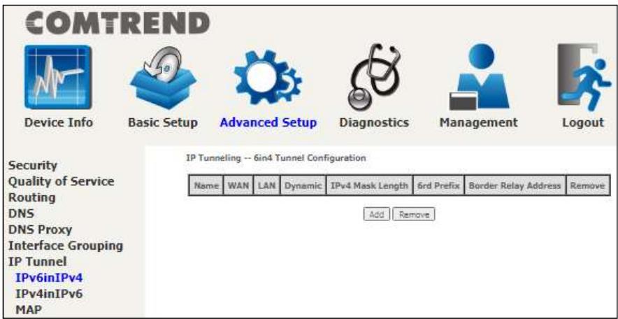
Click the Add button to display the following.
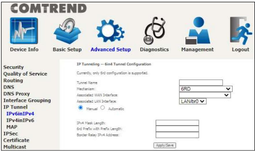
Click Apply/Save to apply and save the settings.
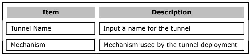
COMTREND
| Associated WAN Interface | Select the WAN interface to be used by the tunnel |
| Associated LAN Interface | Select the LAN interface to be included in the tunnel |
| Manual/Automatic | Select automatic for point-to-multipoint tunneling / manual for point-to-point tunneling |
| IPv4 Mask Length | The subnet mask length used for the IPv4 interface |
| 6rd Prefix with Prefix Length | Prefix and prefix length used for the IPv6 interface |
| Border Relay IPv4 Address | Input the IPv4 address of the other device |
6.7.2 IPv4inIPv6
Configure 4in6 tunneling to encapsulate IPv4 traffic over an IPv6-only environment.
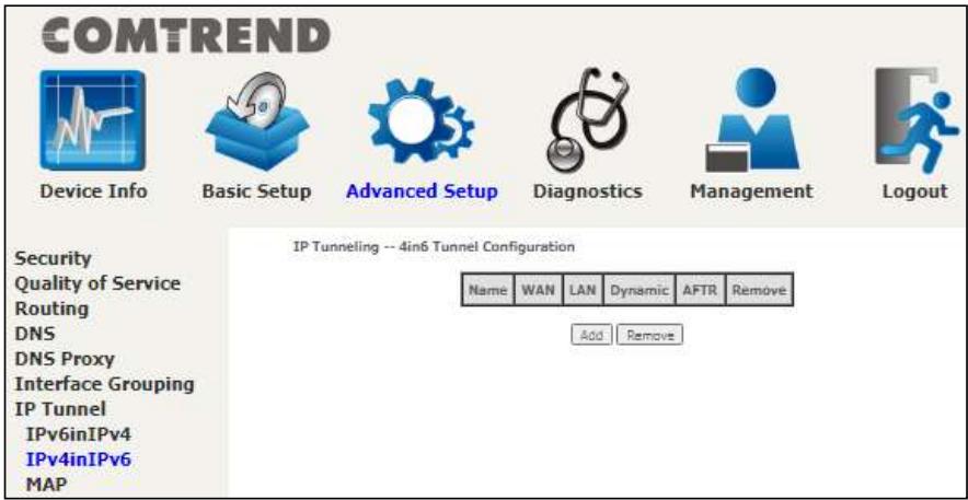
Click the Add button to display the following.
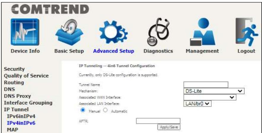
Click Apply/Save to apply and save the settings.
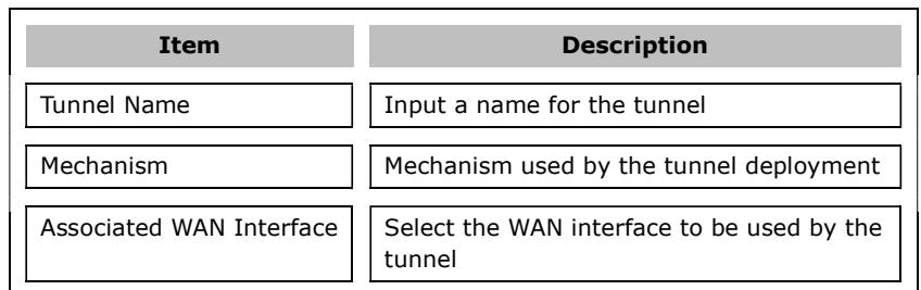
COMTREND
Associated LAN Interface
Select the LAN interface to be included in the tunnel
Manual/Automatic
Select automatic for point-to-multipoint tunneling / manual for point-to-point tunneling
AFTR
Address of Address Family Translation Router
6.7.3 MAP
This page allows you to configure MAP-T and MAP-E entries.
COMTREND

Device Info

Basic Setup

Advanced Setup

Diagnostics

Management

Logout
MAP--MAP-T/MAP-E Configuration
Security
Quality of Service
Routing
DNS
DNS Proxy
Interface Grouping
IP Tunnel
IPv6inIPv4
IPv4inIPv6
MAP


and

P
Click the Add button to display the following.
COMTREND

Device Info

Basic Setup

Advanced Setup

Diagnostics

Management

Logout
Security
Quality of Service
Routing
DNS
DNS Proxy
Interface Grouping
IP Tunnel
IPv6inIPv4
IPv4inIPv6
MAP
IPSec
Certificate
Multicast
Wireless
MAP--MAP-T/MAP-E Configuration
Mechanism
Associated WAN Interface
Associated LAN Interface
4
1
0
。
。

Apply/Seve
Click Apply/Save to apply and save the settings.
The settings shown above are described below.
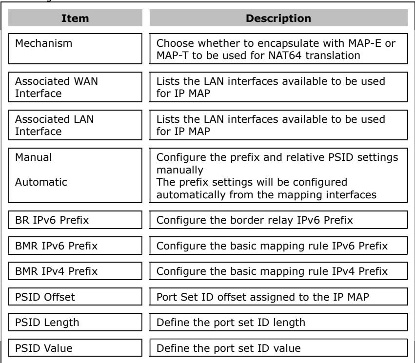
6.8 IPSec
6.8.1 IPSec Tunnel Mode Connections
You can add, edit or remove IPSec tunnel mode connections from this page.
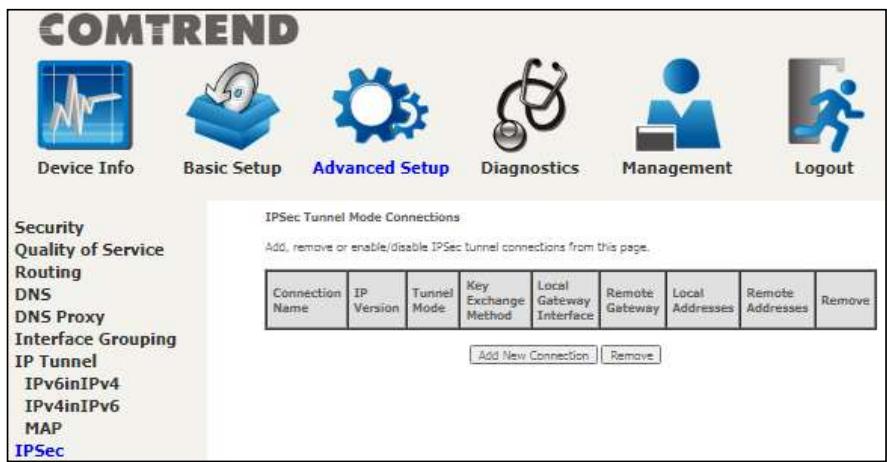
Click Add New Connection to add a new IPSec termination rule.
The following screen will display.
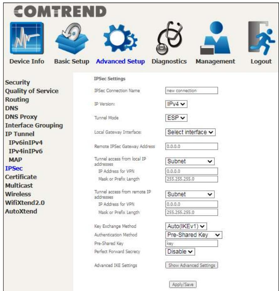
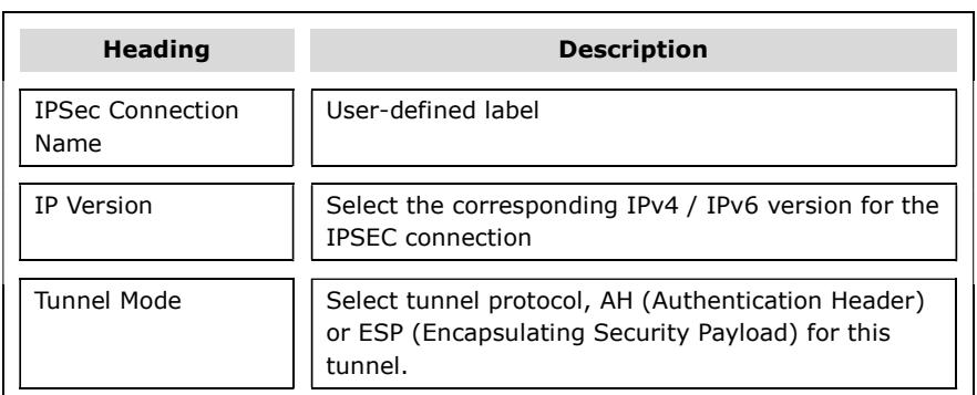
COMTREND
| Local Gateway Interface | Select from the list of wan interface to be used as gateway for the IPSEC connection |
| Remote IPSec Gateway Address | The location of the Remote IPSec Gateway. IP address or domain name can be used. |
| Tunnel access from local IP addresses | Specify the acceptable host IP on the local side. Choose Single or Subnet. |
| IP Address/Subnet Mask for VPN | If you chose Single, please enter the host IP address for VPN. If you chose Subnet, please enter the subnet information for VPN. |
| Tunnel access from remote IP addresses | Specify the acceptable host IP on the remote side. Choose Single or Subnet. |
| IP Address/Subnet Mask for VPN | If you chose Single, please enter the host IP address for VPN. If you chose Subnet, please enter the subnet information for VPN. |
| Key Exchange Method | Select from Auto(IKE) or Manual |
For the Auto(IKE) key exchange method, select Pre-shared key or Certificate (X.509) authentication. For Pre-shared key authentication you must enter a key, while for Certificate (X.509) authentication you must select a certificate from the list.
See the tables below for a summary of all available options.
| Auto(IKE) Key Exchange Method | |
| Pre-Shared Key / Certificate (X.509) | Input Pre-shared key / Choose Certificate |
| Perfect Forward Secrecy | Enable or Disable |
| Advanced IKE Settings | Select Show Advanced Settings to reveal the advanced settings options shown below. |
COMTREND
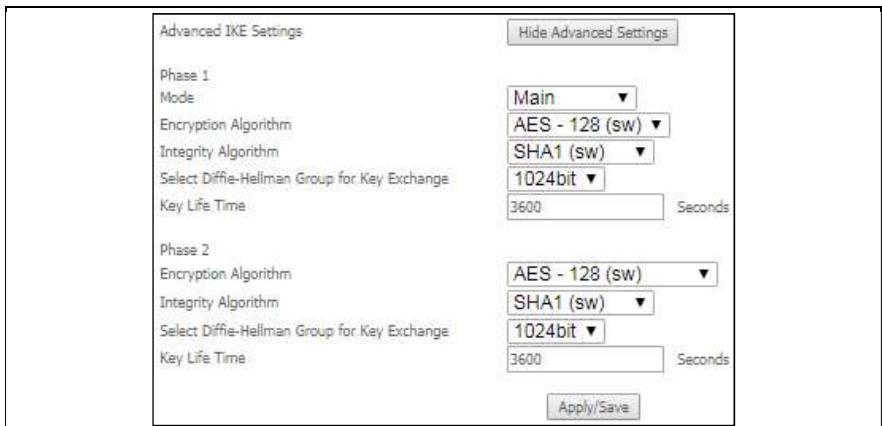
| Advanced IKE Settings | Select Hide Advanced Settings to hide the advanced settings options shown above. |
| Phase 1 / Phase 2 | Choose settings for each phase, the available options are separated with a “/” character. |
| Mode | Main / Aggressive |
| Encryption Algorithm | DES / 3DES / AES 128,192,256 |
| Integrity Algorithm | MD5 / SHA1 |
| Select Diffie-Hellman Group | 768 – 8192 bit |
| Key Life Time | Enter your own or use the default (1 hour) |
The Manual key exchange method options are summarized in the table below.
Manual Key Exchange Method
COMTREND
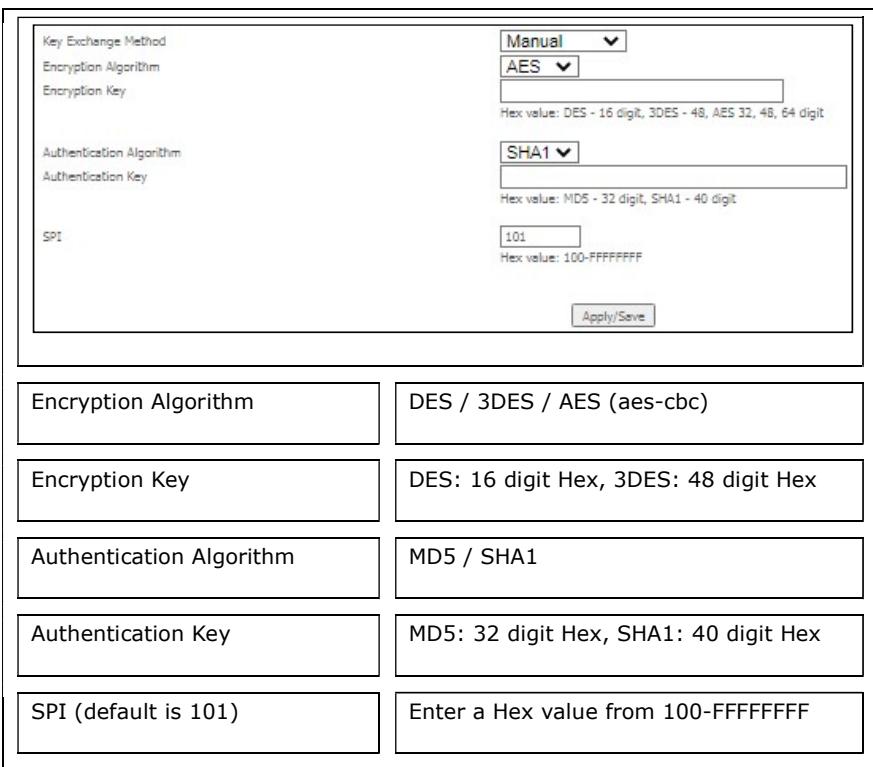
6.9 Certificate
A certificate is a public key, attached with its owner's information (company name, server name, personal real name, contact e-mail, postal address, etc) and digital signatures. There will be one or more digital signatures attached to the certificate, indicating that these entities have verified that this certificate is valid.
6.9.1 Local
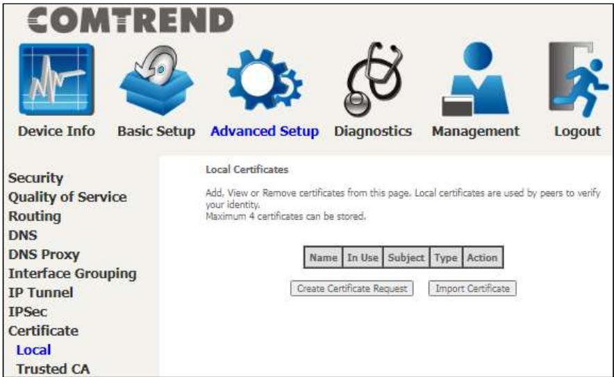
CREATE CERTIFICATE REQUEST
Click Create Certificate Request to generate a certificate-signing request.
The certificate-signing request can be submitted to the vendor/ISP/ITSP to apply for a certificate. Some information must be included in the certificate-signing request. Your vendor/ISP/ITSP will ask you to provide the information they require and to provide the information in the format they regulate. Enter the required information and click Apply to generate a private key and a certificate-signing request. The contents of this application form do not affect the basic parameter settings of the product.
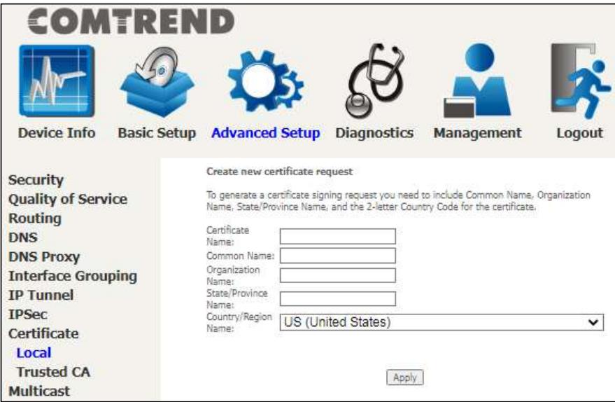
The following table is provided for your reference.
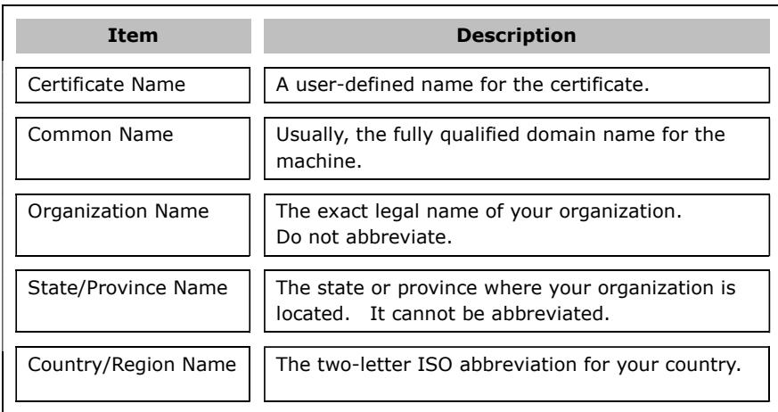
IMPORT CERTIFICATE
Click Import Certificate to paste the certificate content and the private key provided by your vendor/ISP/ITSP into the corresponding boxes shown below.
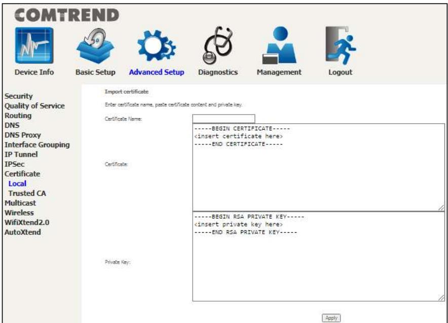
Enter a certificate name and click the Apply button to import the certificate and its private key.
6.9.2 Trusted CA
CA is an abbreviation for Certificate Authority, which is a part of the X.509 system. It is itself a certificate, attached with the owner information of this certificate authority; but its purpose is not encryption/decryption. Its purpose is to sign and issue certificates, in order to prove that these certificates are valid.
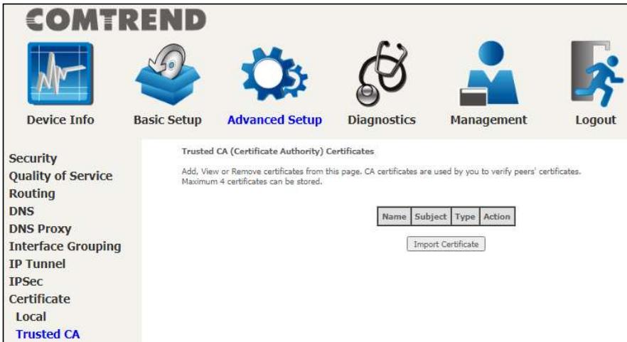
Click Import Certificate to paste the certificate content of your trusted CA. The CA certificate content will be provided by your vendor/ISP/ITSP and is used to authenticate the Auto-Configuration Server (ACS) that the CPE will connect to.
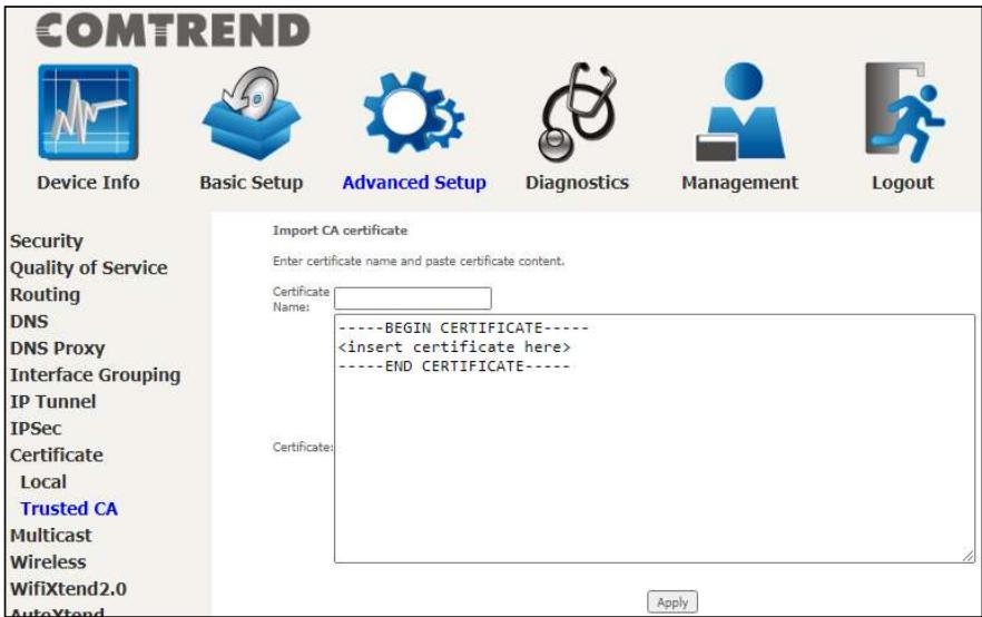
Enter a certificate name and click Apply to import the CA certificate.
6.10 Multicast
Input new IGMP or MLD protocol configuration fields if you want modify default values shown. Then click Apply/Save.

COMTREND
Device Info

Basic Setup

Advanced Setup

Diagnostics

Management

Logout
Security
Quality of Service
Routing
DNS
DNS Proxy
Interface Grouping
IP Tunnel
IPSec
Certificate
Multicast
Wireless
WifiXtend2.0
AutoXtend
Multicast Precedence:
Multicast Strict Grouping Enforcement:

Disable
lower value, higher priority
IGMP Configuration
Enter IGMP protocol configuration fields if you want modify default values shown below.
Default Version:
Query Interval:
Query Response Interval:
Last Member Query Interval:
Robustness Value:
Maximum Multicast Groups:
Maximum Multicast Data Sources (for IGMPv3)
Maximum Multicast Group Members:
Fast Leave Enables
IGMP Group Exception List
| Group Address | Mask/Mask bits | Remove |
| 224.0.0.0 | 255.255.255.0 | |
| 239.255.255.250 | 255.255.255.255 | ☐ |
| 224.0.255.135 | 255.255.255.255 | ☐ |
Remove Checked Entries
MLD Configuration
Enter MLD protocol (IPv6 Multicast) configuration fields if you want modify default values shown below.
Default Version:
Query Interval:
Query Response Interval:
Last Member Query Intervals
Robustness Value:
Maximum Multicast Groups:
Maximum Multicast Data Sources (for mldv2):
Maximum Multicast Group Members:
Fast Leave Enables
MLD Group Exception List
| Group Address | Mask/Mask bits | Remove |
| f01::0000 | ffff::0000 | |
| f02::0000 | ffff::0000 | |
| f05::0001:0003 | ffff::fff,fff,fff,fff,fff,fff,fff | ☐ |
| Add |
Remove Checked Entries
Apply/Save
Multicast Precedence: Select precedence of multicast packets.
Multicast Strict Grouping Enforcement: Enable/Disable multicast strict grouping.
COMTREND
| Item | Description |
| Default Version | Define IGMP using version with video server. |
| Query Interval | The query interval is the amount of time in seconds between IGMP General Query messages sent by the router (if the router is the querier on this subnet). The default query interval is 125 seconds. |
| Query Response Interval | The query response interval is the maximum amount of time in seconds that the IGMP router waits to receive a response to a General Query message. The query response interval is the Maximum Response Time field in the IGMP v2 Host Membership Query message header. The default query response interval is 10 seconds and must be less than the query interval. |
| Last Member Query Interval | The last member query interval is the amount of time in seconds that the IGMP router waits to receive a response to a Group-Specific Query message. The last member query interval is also the amount of time in seconds between successive Group-Specific Query messages. The default last member query interval is 10 seconds. |
| Robustness Value | The robustness variable is a way of indicating how susceptible the subnet is to lost packets. IGMP can recover from robustness variable minus 1 lost IGMP packets. The robustness variable should be set to a value of 2 or greater. The default robustness variable value is 2. |
| Maximum Multicast Groups | Setting the maximum number of Multicast groups. |
| Maximum Multicast Data Sources (for IGMPv3) | Define the maximum multicast video stream number. |
| Maximum Multicast Group Members | Setting the maximum number of groups that ports can accept. |
| Fast Leave Enable | When you enable IGMP fast-leave processing, the switch immediately removes a port when it detects an IGMP version 2 leave message on that port. |
COMTREND
IGMP Group Exception List / MLD Group Exception List
| Item | Description |
| Group Address | This is the delimited list of ignored multicast addresses being queried when sending a Group-Specific or Group-and-Source-Specific Query. |
| Mask/Mask Bits | This is the delimited list of ignored multicast mask being queried when sending a Group-Specific or Group-and-Source-Specific Query. |
| Remove | Allows a user to remove a specific item in the exception list. |
6.11 Wireless
6.11.1 SSID
This page allows you to configure the Virtual interfaces for each Physical interface.
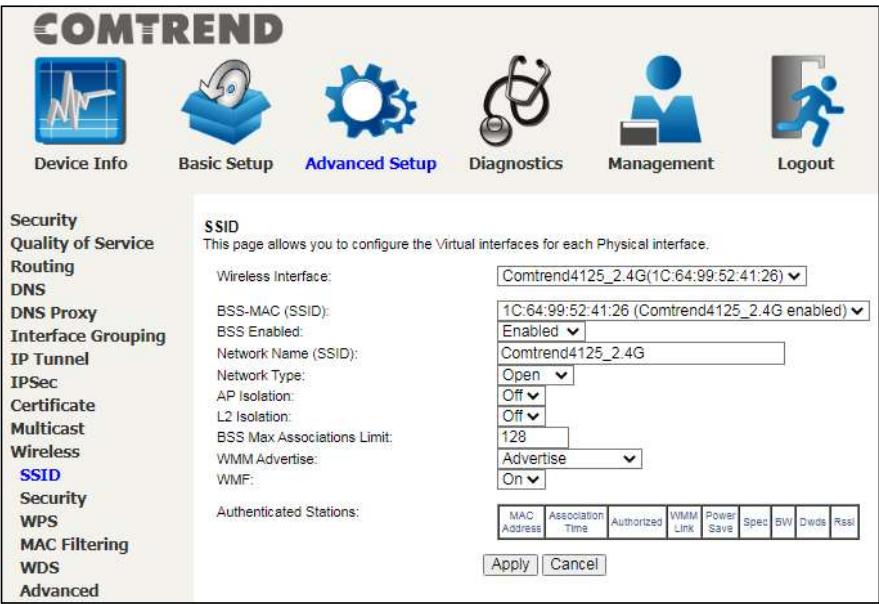
Click the Apply button to apply your changes. The settings shown above are described below.
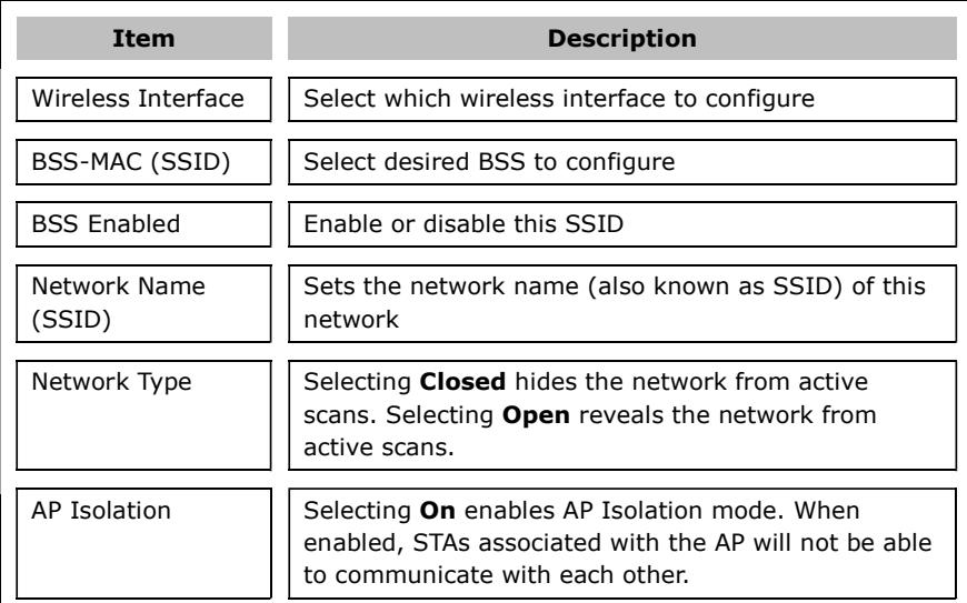
COMTREND
| L2 Isolation | Wireless clients on the guest network cannot access hardwired LAN clients |
| BSS Max Associations Limit | Sets the maximum associations for this BSS |
| WMM Advertise | When WMM is enabled for the radio, selecting On allows WMM to be advertised in beacons and probes for this BSS. Off disables advertisement of WMM in beacons and probes. |
| WMF | Choose On to enable Wireless Multicast Forwarding on this BSS. Off disables this feature. |
| MAC Address | Lists the MAC address of all the stations. |
| Association Time | Lists all the stations that are associated with the Access Point, along with the amount of time since packets were transferred to and from each station. If a station is idle for too long, it is removed from this list. |
| Authorized | Lists those devices with authorized access |
| WMM Link | Lists those devices that utilize WMM |
| Power Save | Lists those devices that utilize the Power Save Feature |
| Spec | Wi-Fi Spec |
| BW | Bandwidth |
| Dwds | Lists the devices that utilize Dynamic WDS |
| Rssi | Received Signal Strength Indicator |
6.11.2 Security
This page allows you to configure security for the wireless LAN interfaces.
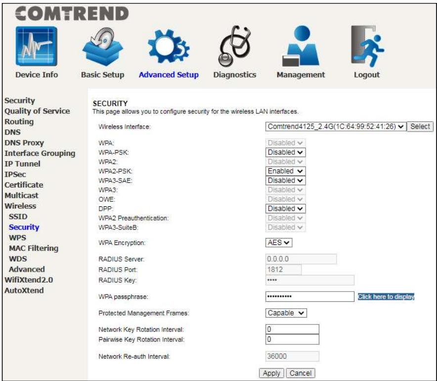
Click the Apply button to apply your changes. For information on each parameter, move the cursor over the parameter that you are interested in (as shown here).
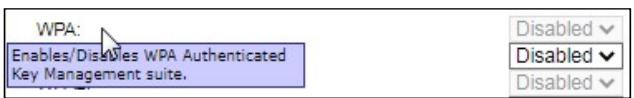
The descriptions are also shown below.
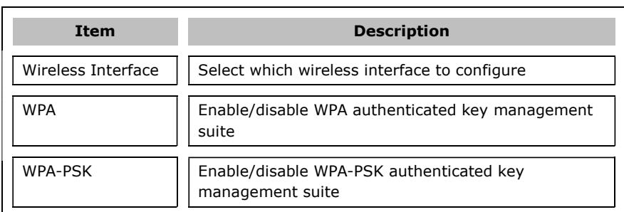
COMTREND
| WPA2 | Enable/disable WPA2 authenticated key management suite |
| WPA2-PSK | Enable/disable WPA2-PSK authenticated key management suite |
| WPA3-SAE | Enable/disable WPA3-SAE authenticated key management suite |
| WPA3 | Enable/disable WPA3 authenticated key management suite |
| OWE | Enable/disable OWE authenticated key management suite |
| DPP | Enable/disable DPP authenticated key management suite |
| WPA2 Preauthentication | Enable/disable WPA2 Preauthenticated key management suite |
| WPA3-SuiteB | Enable/disable WPA3-SuiteB key management suite |
| WPA Encryption | Select the WPA encryption algorithm |
| RADIUS Server | Set the IP of the RADIUS (Remote Authentication Dial In User Service) to use for authentication and dynamic key derivation |
| RADIUS Port | Set the UDP port number of the RADIUS server. The port number is usually 1812 or 1645 and depends upon the server. |
| RADIUS Key | Set the shared secret for the RADIUS connection |
| WPA passphrase | Set the WPA passphrase |
| Protected Management Frames | Wi-Fi CERTIFIED WPA2 with Protected Management Frames provides a WPA2-level of protection for unicast and multicast management action frames. |
| Network Key Rotation Interval | Set the Network Key Rotation interval in seconds. Leave blank or set to zero to disable the rotation. |
| Pairwise Key Rotation Interval | Set the Pairwise Key Rotation interval in seconds. Leave blank or set to zero to disable the rotation. |
COMTREND
Network Reauth Interval
Set the Network Key Re-authentication interval in seconds. Leave blank or set to zero to disable periodic network re-authentication.
6.11.3 WPS
This page allows you to configure WPS.
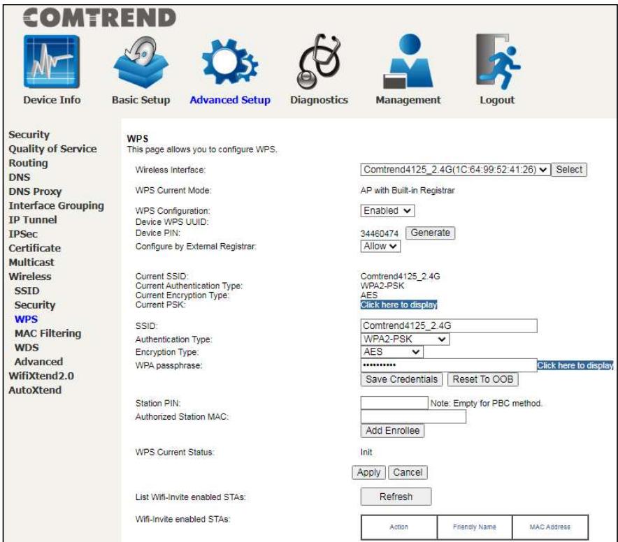
Click the Apply button to apply your changes. For information on each parameter, move the cursor over the parameter that you are interested in (as shown here).
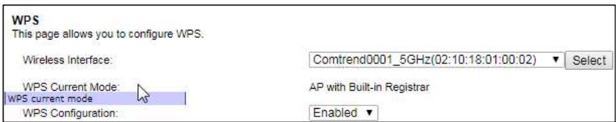
The descriptions are also shown below.
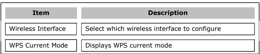
COMTREND
| WPS Configuration | Enable/Disable Wi-Fi simple config mode |
| Device WPS UUID | Displays the WPS UUID number of this device |
| Device PIN | Displays the PIN number for this device. Click the Generate button to change a unique Device PIN number. |
| Configure by External Registrar | Set Allow/Deny wireless external registrar to getconfigure AP security through AP PIN |
| Current SSID | Displays the current SSID |
| Current Authentication Type | Displays the current authentication type |
| Current Encryption Type | Displays the current encryption type |
| Current PSK | Displays the current PSK by clicking Click here to display |
| SSID | Set the network name (also known as the SSID) of this network |
| Authentication Type | Select the authentication type from the drop-down menu |
| Encryption Type | Select the encryption type from the drop-down menu |
| WPA passphrase | Set the WPA passphrase. Click the Save Credentials button to save the Wi-Fi access password. Click the Reset To OOB (Out of Box configure) button to restore SSID/ Authentication Type / Encryption Type / WPA passphrase default setting. |
| Station PIN | Input the station PIN to verify expected station. Note: Empty for PBC method. |
| Authorized Station MAC | Input the authorized station MAC address. Click the Add Enrollee button to start a WPS process. This WPS process is only for the client whose MAC is typed in this field. |
| WPS Current Status | Displays the WPS current status |
| List Wifi-Invite enabled STAs | Click the Refresh button to find WiFi-Invite enabled STAs |
| Wifi-Invite enabled STAs | Displays the list of WiFi-Invite enabled STAs |
6.11.4 MAC Filtering
This page allows you to configure the MAC Filtering for each Physical interface.
| COMTREND | ||||
| Device Info | Basic Setup | Advanced Setup | Diagnostics | Management |
| Security | MAC Filtering | |||
| Quality of Service | This page allows you to configure the MAC Filtering for each Physical interface. | |||
| Routing | Wireless Interface: | Comtrend4125_2.4G(1C:64:99:52:41:26) | ||
| DNS | ||||
| DNS Proxy | BSS-MAC (SSID): | 1C:64:99:52:41:26 (Comtrend4125_2.4G enabled) | ||
| Interface Grouping | MAC Restrict Mode: | Disabled | ||
| IP Tunnel | MAC filter based Probe Response: | On | ||
| IPSec | MAC Addresses: | |||
| Certificate | ||||
| Multicast | ||||
| Wireless | ||||
| SSID | ||||
| Security | ||||
| WPS | ||||
| MAC Filtering | ||||
| WDS | ||||
| Advanced | Apply | Cancel | ||
Click the Apply button to apply your changes. For information on each parameter, move the cursor over the parameter that you are interested in (as shown here).
| MAC Restrict Mode: Selects whether clients with the specified MAC address are allowed or denied wireless access. | Disabled▼ | |
| On▼ | ||
The descriptions are also shown below.
| Item | Description |
| Wireless Interface | Select which wireless interface to configure |
COMTREND
BSS-MAC (SSID)
MAC Restrict Mode
MAC filter based Probe Response
MAC Addresses
Select desired BSS to configure
Select whether clients with the specified MAC address are allowed or denied wireless access
Enable/Disable MAC filter based probe response mode
Allow/Deny wireless access to clients with the specified MAC addresses. The MAC address format is xx:xx:xx:xx:xx:xx.
6.11.5 WDS
The wireless distribution system supports extended networking of wireless access points and can be configured as described below.

COMTREND
Device Info

Basic Setup

Advanced Setup

Diagnostics

Management

Logout
Security
Quality of Service
Routing
DNS
DNS Proxy
Interface Grouping
IP Tunnel
IPSec
Certificate
Multicast
Wireless
SSID
Security
WPS
MAC Filtering
WDS
Wireless Distribution System (WDS)
WDS settings need reboot to apply.
Wireless Interface:
Peer MAC Address:
Restriction:
Link Detection Interval:
Comtrend4125_2.4G(1C:64:99:52:41:26)
MAC Address
Link Status
Enabled
1
apply
Cancel
Click the Apply button to apply your changes. For information on each parameter, move the cursor over the parameter that you are interested in (as shown here).
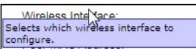
Comtrend80D1_2.4GHz(1C:64:99:32:80:D2)
MAC Address
Link Status
The descriptions are also shown below.
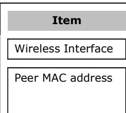
Description
Select which wireless interface to configure
Enter the peer wireless MAC addresses of any member that should be part of the Wireless Distribution System (WDS)
Select Disabled to disable the WDS restriction. Any WDS (including the ones listed in Remote Bridges) will be granted access. Select Enabled to enable WDS restriction. Only those bridges listed in Remote Bridges will be granted access.
Link Direction Interval
Set the WDS link detection interval in seconds. Leave blank or set to zero to disable the detection.
Note: With reference to the above setup, please ensure that the conditions below are met, and both devices are rebooted afterwards:
- Ensure that the first Comtrend device (home router) does not use the same IP address as the second Comtrend wireless device (wireless bridge). See section 5.3 LAN, for details on how to change the IP address.
COMTREND

Device Info

Basic Setup

Advanced Setup

Diagnostics

Management

Logout
WAN Setup
NAT
LAN
Lan VLAN Setting
IPv6 Autoconfig
UPnP
Parental Control
Home Networking
Wireless
WifiXtend2.0
AutoXtend
Local Area Network (LAN) Setup
Configure the Broadband Router IP Address and Subnet Mask for LAN interface. GroupName Default
Enable DHCP Client
IP Address:
Subnet Mask:
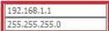
Enable IGMP Snooping
Standard Mode
Blocking Mode
Enable LAN side firewall
Disable DHCP Server
Enable DHCP Service
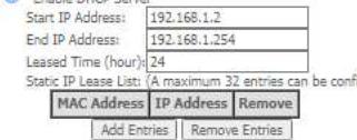
Apply/Save
- Both devices need to have the same fixed channel. See section 6.11.6 Advanced for details.

COMTREND
Device Info

Basic Setup

Advanced Setup

Diagnostics

Management

Logout
Security Quality of Service
Routing
DNS
DNS Proxy
Interface Grouping
IP Tunnel
IPSec
Certificate
Multicast
Wireless
SSID
Security
WPS
MAC Filtering
WDS
Advanced
WifiXtend2.0
AutoXtend
Radio
This page allows you to configure the Physical Wireless interfaces,
Wireless Interface
14
802.11 Band:
Channel Specification
Bandwidth
VLAN Priority Support
…
OSS Coexistence
Transmit Power:
Max Associations Limit:
XPressTM Technology:
Beamforming transmission (BFR):
Beamforming reception (BFE):
MU-MIMO TX
RIFS Mode Advertisement:
WMM Support:
No-Acknowledgement:
APSD Support
Enable IGMP Proxy:
BandSteering Daemon
Airtime Fairness:
Enable 802.11ax:
Comtrend4125_2.4G(1C:64:99:52:41:26)
Enabled
2.4GHz Current: 2.4 GHz
Auto Current: 1 ***interference Level; Acceptable
20MHz√Current:20MHz
Off
100%
32
On
VHT MU +HE MU+CQI BFR
VHTMU+HE MU BFE
Enabled
Auto
On
Off
On
Disable
Disable
Enable
On
Apply Cancel
- Both devices need to have a (different) fixed access SSID (Network Name). See section 6.11.1 SSID for details.

COMTREND
Device Info

Basic Setup

Advanced Setup

Diagnostics

Management

Logout
WAN Setup
NAT
LAN
Parental Control
Home Networking
Wireless
SSID
Security
WifiXtend2.0
AutoXtend
SSID
This page allows you to configure the Virtual interfaces for each Physical interface.
Wireless Interface:
BSS-MAC (SSID):
BSS Enabled:
Network Name (SSID):
Network Type
AP Isolation:
L2 Isolation:
BSS Max Associations Limit:
WMM Advertise:
WMF:
Authenticated Stations:
Comtrend4125_2.4G(1C:64:99:52:41:26)
1C:64:99:52:41:26(Comtrend4125 2.4G enabled)
Enabled
Comtrend4125_2.4G
Open
Off
Off
128
Advertise
On
MACAssociation Authorized VMM Power SpA SW Davis Basi
Address Time Authorized Link Save Spec Sw Swd Nee
Apply | Cancel
- Both devices need to have WPA2-PSK enabled. See section 6.11.2 Security for details.
COMTREND

Device Info

Basic Setup

Advanced Setup

Diagnostics

Management

Logout
WAN Setup
NAT
LAN
Parental Control
Home Networking
Wireless
SSID
Security
WifiXtend2.0
AutoXtend
SECURITY
This page allows you to configure security for the wireless LAN interfaces.
Wireless Interface
WPA:
WPA-PSK:
WPA2-PSK
WP43-SAE:
WPA3
OWE
DPP:
WPA2 Preauthentication:
WPA3-SuiteB:
WPA Encryption:
RADIUS Server:
RADIUS Port
RADIUS Key:
WPA passphrase:
Protected Management Frames
Network Key Rotation Interval:
Pairwise Key Rotation Interval:
Network Re-auth Interval:
Comtrend4125_2.4G(1C:64:99:52:41:26) Select
Disabled
Disabled
Enabled
Disabled
Disabled
Disabled
Disabled
Disabled
Disabled
AES
0000
1812
中
Click here to display
Capable
0
0
36000
Apply
ncel
- Both devices (A & B) need to have each other's MAC address. See section 6.11.5 WDS for details.
COMTREND

Device Info

Basic Setup

Advanced Setup

Diagnostics

Management

Logout
Security
Quality of Service
Routing
DNS
DNS Proxy
Interface Grouping
IP Tunnel
IPSec
Certificate
Multicast
Wireless
SSID
Security
WPS
MAC Filtering
WDS
Wireless Distribution System (WDS)
WDS settings need reboot to apply.
Wireless Interface:
Peer MAC Address:
Restriction:
Link Detection Interval:
Comtrend4125_2.4G(1C:64:99:52:41:26)
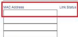
Enabled
1
Apply Cancel
- Now make sure to reboot both devices. See section 8.9 Reboot for details.
COMTREND

Device Info

Basic Setup

Advanced Setup

Diagnostics

Management

Logout
Settings
System Log
SNMP Agent
TR-069 Client
STUN Client
Internet Time
Access Control
Update Software
Reboot
Click the button below to reboot the router.

6.11.6 Advanced
This page allows you to configure the Physical Wireless interfaces.
2.4GHz
COMTREND

Device Info

Basic Setup

Advanced Setup

Diagnostics

Management

Logout
Security
Quality of Service
Routing
DNS
DNS Proxy
Interface Grouping
IP Tunnel
IPSec
Certificate
Multicast
Wireless
SSID
Security
WPS
MAC Filtering
WDS
Advanced
WifiXtend2.0
AutoXtend
Radio
This page allows you to configure the Physical Wireless interfaces.
Wireless Interface:
Interface
802.11 Band:
Channel Specification:
Bandwidth
VLAN Priority Support
OBSS Coexistence:
Transmit Power:
Max Associations Limit:
XPressTM Technology:
Beamforming transmission (BFR):
Beamforming reception (BFE):
MU-MIMO TX:
RIFS Mode Advertisement:
WMM Support:
No-Acknowledgement
APSD Support
EnableIGMP Proxy:
BandSteering Daemon
Airtime Fairness:
Enable 802.11ax:
Comtrend4125_2.4G(1C:64:99:52:41:26)
Enabled
2.4 GHz√ Current: 2.4 GHz
Auto Current:1 ***Interference Level:Acceptable
20MHzCurrent:20MHz
Off
Off
100%
32
On
VHT MU + HE MU+CQI BFR
VHT MU +HE MU BFE
Enabled
Auto
On
Off
On
Disable
Disable
Enable
On
Apply Cancel
5GHz
COMTREND

Device Info

Basic Setup

Advanced Setup

Diagnostics

Management

Logout
Security
Quality of Service
Routing
DNS
DNS Proxy
Interface Grouping
IP Tunnel
IPSec
Certificate
Multicast
Wireless
SSID
Security
WPS
MAC Filtering
WDS
Advanced
WifiXtend2.0
AutoXtend
Radio
This page allows you to configure the Physical Wireless interfaces.
Wireless Interface
Interface:
802.11 Band:
Channel Specification:
Bandwidth
VLAN Priority Support:
OBSS Coexistence:
Transmit Power
DFS Channel Selection
Max Associations Limit:
XPressTM Technology:
Beamforming transmission (BFR)
Beamforming reception (BFE)
MU-MIMO TX:
RIFS Mode Advertisement:
WMM Support:
No-Acknowledgement:
APSD Support:
Enable IGMP Proxy:
BandSteering Daemon
Airtime Fairness:
Enable 802.11ax:
Comtrend4125_5G(1C:64:99:52:41:28)
Enabled
5 GHz√ Current: 5 GHz
Auto Current:177 **interference Level:Acceptable
20MHz Current:20MHz
Off
Off
100%
DFS Reentry
32
On
VHT MU + HE MU+CQI BFR
VHT MU + HE MU BFE
Enabled
Auto
On
Off
On
Disable
Disable
Enable
On
Apply 6
6GHz
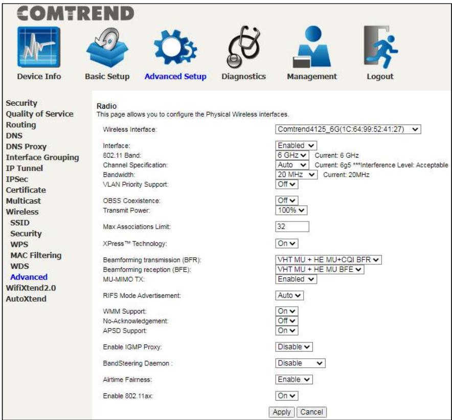
Click the Apply button to apply your changes.
For information on each parameter, move the cursor over the parameter that you are interested in (as shown here).

The descriptions are also shown below.
COMTREND
| Interface | Enable/Disable the wireless interface |
| 802.11 Band | Select the 802.11 band to use |
| Channel Specification | Select a channel specification |
| Bandwidth | Select channel bandwidth |
| VLAN Priority Support | Advertise packet priority using VLAN tag |
| OBSS Coexistence | Enable/Disable overlapping BSS coexistence aka 20/40 coex |
| Transmit Power | Select the transmit power percentage |
| Max Associations Limit | Set the number of associations the driver should accept |
| Xpress Technology | Enable/Disable Xpress mode |
| Beamforming transmission (BFR) | This is a versatile technique for signal transmission from a number of antennas to one or multiple users. In wireless networks it increases signal power for the intended user and reduces interference to non-intended users.VHT MU BFR: Wi-Fi 5 Multi User Beamforming transmissionHE MU BFR: Wi-Fi 6 Multi User Beamforming transmissionVHT MU + HE MU BFR: Wi-Fi 5 & Wi-Fi 6 Multi User Beamforming transmissionDisabled - Disables beamforming transmission |
| Beamforming reception (BFE) | This is a versatile technique for signal reception from a number of antennas to one or multiple users. In wireless networks it increases signal power for the intended user and reduces interference to non-intended users.VHT MU BFE: Wi-Fi 5 Multi User Beamforming receptionHE MU BFE: Wi-Fi 6 Multi User |
COMTREND
| Beamforming reception VHT MU + HE MU BFE: Wi-Fi 5 & Wi-Fi 6 Multi User Beamforming reception Disabled - Disables beamforming reception | |
| MU-MIMO TX | (MU) Multi-user MIMO transmission is a set of multiple-input and multiple-output technologies for multipath wireless communication, in which multiple users or terminals, each radioing over one or more antennas, communicate with one another. Client devices that support Wi-Fi 6 are highly recommended to enable this feature. Disabled: Enables MU-MIMO transmission Note: Disabling MU-MIMO TX, will also disable HE (Wi-Fi 6) MU-MIMO Enabled: Enables MU-MIMO transmission Auto: In this mode of operation, the Access Point will detect the wireless stations currently present in the network to determine the operation mode |
| Wifi 6 (11ax) | Control Wifi 6 features |
| RIFS Mode Advertisement | Select the RIFS (Reduced Inter-Frame Spacing) mode to advertise in beacons and probe responses |
| WMM Support | Enable/Disable WMM support |
| No-Acknowledgement | Enable/Disable EMM No-acknowledgement |
| APSD Support | Enable/Disable Automatic Power Save Technology |
| Enable IGMP Proxy | Enable/Disable IGMP Proxy |
| BandSteering Deamon | This is a function that automatically steers anyone connecting to a wireless network to the best available frequency band (e.g. from 5G to 2.4G or vice versa) providing an |
COMTREND

optimized performance for the client. Please note that this feature is not supported in this software version.
Default is Disable
Select Standalone to enable BandSteering
Airtime Fairness
Enable/Disable airtime fairness between multiple links
Enable 802.11ax
Enabled by default. Select Off to disable AX mode
6.12 AutoXtend
AutoXtend is a function to construct and optimize a mesh-network. To select information to synchronize with all mesh-network nodes, please check the desired item and click the Apply/Save button.
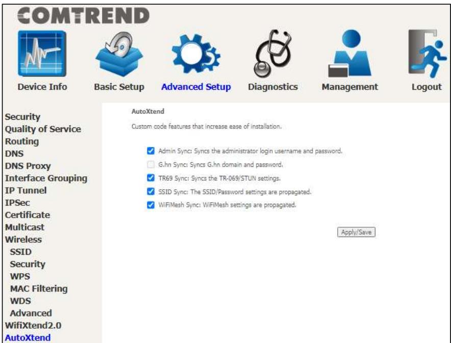
To enable the AutoXtend features, check the required checkboxes and click the Apply/Save button.
Chapter 7 Diagnostics
You can reach this page by clicking on the following icon located at the top of the screen.

Diagnostics
7.1 Diagnostics - Individual Tests
The first Diagnostics screen is a dashboard that shows overall connection status.
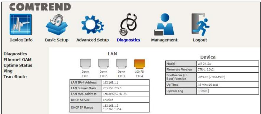
Click the Diagnostics Menu item on the left side of the screen to display the individual connections.