MOTOTRBO R2 - Radio MOTOROLA - Free user manual and instructions
Find the device manual for free MOTOTRBO R2 MOTOROLA in PDF.
Download the instructions for your Radio in PDF format for free! Find your manual MOTOTRBO R2 - MOTOROLA and take your electronic device back in hand. On this page are published all the documents necessary for the use of your device. MOTOTRBO R2 by MOTOROLA.
USER MANUAL MOTOTRBO R2 MOTOROLA
© 2022 Motorola Solutions, Inc. All rights reserved MNO09532A01-AA
- Contents Contents List of Figures sise 5 List of Tables
- sine 6 Legal and Support p. 7
- Intellectual Property and Regulatory Notices. Legal and Compliance Statements…… Supplier's Declaration of Conformity. Important Safety Information Notice to Users (FCC). Notice to Users (Industry Canada) p. 9
Chapter 1: Read Me First .10
1.1 Software Version -11
Chapter 2: Radio Care.
Chapter 3: Getting Started
3.1 Charging the Battery.
3.2 Attaching the Battery.
3.3 Removing the Battery,
3.7 Removing the Belt Clip.
3.8 Turning the Radio On.
3.9 Turning the Radio Off.
3.10 Adjusting the Volume
Chapter 4: Radio OV@rvieW.......... nn nnnrrrrennrrerrenrenrennenneeneenmennenneennennennns
4.2 LED Indications...
5.2 IP Site Connect.
Chapter 6: Zone and Channel Selections.…..….......................….... 20
6.1 Selecting Zones.
6.2 Selecting Channels
7.2 Receiving and Responding to Calls on the Radio...
Chapter 8: Voice Interrupt....…..…......................…...nnnns
8.1 Enabling the Voice Interrupt.
10.3 Call Alert Operation
10.3.1 Making Call Alerts.
10.3.2 Responding to Call Alerts.
10.4 Call Indicator Settings.
10.4.1 Escalert Mode Tone
10.5 Emergency Operation
10.5.1 Sending Emergency Alarms.
10.5.2 Sending Emergency Alarms with Call...
10.5.3 Sending Emergency Alarms with Voice to Follow.
10.5.4 Reinitiating the Emergency Mode.
10.5.5 Exiting the Emergency Mode
10.7.1 Starting and Stopping Automatic Site Search.
10.7.2 Enabling Manual Site Search
10.8 Monitor Feature...
10.9.2 Scan Talkback.
10.9.3 Nuisance Channels...
10.9.3.1 Deleting Nuisance Channel:
10.11.2 Extending the Rental Period.
Chapter 11: Utilities...
11.1 Checking the Battery Strength
11.2 Password Lock...
11.2.1 Accessing Radios with Password.
11.2.2 Unlocking Radios in Locked State.
11.3 Setting Radio Tones/Alerts.
11.4 Setting Power Levels
11.7 Setting the Voice Announcement.
11.9 Voice Operating Transmission
11.102 Setting Privacy.
Chapter 12: Authorized Accessories List... a1
MN009532A01-AA List of Figures List of Figures Figure 1: R2 Figure 2: Radio Overview
List of Tables List of Tables Table 1: Table 2: Table 3: Table 4: Table 5: Table 6: Table 7: Table 8: Table 9: Table 10: Emergency Modes Table 11: Scan Methods Table 12: Scan Talkback Type Table 13: Privacy Types and Settings Table 14: Antenna Table 15: Batteries Table 16: Cables Table 17: Carry Devices . Table 18: Chargers Table 19: Earbuds and Earpieces Table 20: Headsets and Headset Accessories Table 21: Remote Speaker Microphones Table 22: Surveillance Accessories Special Notations The Feature Access and Indications of the Radio IP Specification Callout Legend . Assignable Radio Functions LED Indications Number of Supported Zones and Channels Types of Radio Calls Auto-Range Transponder System Indications
MN009532A01-AA Legal and Support Legal and Support Intellectual Property and Regulatory Notices Copyrights The Motorola Solutions products described in this document may include copyrighted Motorola Solutions computer programs. Laws in the United States and other countries preserve for Motorola Solutions certain exclusive rights for copyrighted computer programs. Accordingly, any copyrighted Motorola Solutions computer programs contained in the Motorola Solutions products described in this document may not be copied or reproduced in any manner without the express written permission of Motorola Solutions. No part of this document may be reproduced, transmitted, stored in a retrieval system, or translated into any language or computer language, in any form or by any means, without the prior written permission of Motorola Solutions, Inc. Trademarks MOTOROLA, MOTO, MOTOROLA SOLUTIONS, and the Stylized M Logo are trademarks or registered trademarks of Motorola Trademark Holdings, LLC and are used under license. All other trademarks are the property of their respective owners. License Rights The purchase of Motorola Solutions products shall not be deemed to grant either directly or by implication, estoppel or otherwise, any license under the copyrights, patents or patent applications of Motorola Solutions, except for the normal non-exclusive, royalty-free license to use that arises by operation of law in the sale of a product. Open Source Content This product may contain Open Source software used under license. Refer to the product installation media for full Open Source Legal Notices and Attribution content. European Union (EU) and United Kingdom (UK) Waste of Electrical and Electronic Equipment (WEÉEE) Directive The European Union's WEEE directive and the UK's WEEE regulation require that products sold into EU countries and the UK must have the crossed-out wheelie bin label on the product (or the package in some cases). As defined by the WEEE directive, this crossed-out wheelie bin label means that customers and end-users in EU and UK countries should not dispose of electronic and electrical equipment or accessories in household waste. Customers or end-users in EU and UK countries should contact their local equipment supplier representative or service centre for information about the waste collection system in their country. Disclaimer Please note that certain features, facilities, and capabilities described in this document may not be applicable to or licensed for use on a specific system, or may be dependent upon the characteristics of a specific mobile subscriber unit or configuration of certain parameters. Please refer to your Motorola Solutions contact for further information.
Legal and Support © 2022 Motorola Solutions, Inc. AIl Rights Reserved Legal and Compliance Statements Supplier's Declaration of Conformity Supplier's Declaration of Conformity Per FCC CFR 47 Part 2 Section 2.1077(a)
Responsible Party Name: Motorola Solutions, Inc. Address: 2000 Progress Pkwy, Schaumburg, IL. 60196 Phone Number: 1-800-927-2744 Hereby declares that the product: Model Name: R2 conforms to the following regulations: FCC Part 15, subpart B, section 15.107(a), 15.107(d), and section 15.109(a) Class B Digital Device As a personal computer peripheral, this device complies with Part 15 of the FCC Rules. Operation is subject to the following two conditions: 1 This device may not cause harmful interference, and 2 This device must accept any interference received, including interference that may cause unde- sired operation. [7 NOTE: This equipment has been tested and found to comply with the limits for a Class B digital device, pursuant to part 15 of the FCC Rules. These limits are designed to pro- vide reasonable protection against harmful interference in a residential installation. This equipment generates, uses and can radiate radio frequency energy and, if not installed and used in accordance with the instructions, may cause harmful interference to radio communications. However, there is no guarantee that interference will not occur in a particular installation. If this equipment does cause harmful interference to radio or television reception, which can be determined by turning the equipment off and on, the user is encouraged to try to correct the interference by one or more of the following measures: + Reorient or relocate the receiving antenna. *__ Increase the separation between the equipment and receiver. *__ Connect the equipment into an outlet on a circuit different from that to which the receiver is connected. + Consult the dealer or an experienced radio or TV technician for help.
MN009532A01-AA Legal and Support Important Safety Information RF Energy Exposure and Product Safety Guide for Portable Two-Way Radios ÂÀ CAUTION: This radio is restricted to Occupational use only. Before using the radio, read the RF Energy Exposure and Product Safety Guide that comes with the radio. This guide contains operating instructions for safe usage, RF energy awareness, and control for compliance with applicable standards and regulations. Any modification to this device, not expressly authorized by Motorola Solutions, may void the user's authority to operate this device. Under Industry Canada regulations, this radio transmitter may only operate using an antenna of a type and maximum (or lesser) gain approved for the transmitter by Industry Canada. To reduce potential radio interference to other users, the antenna type and its gain should be so chosen that the equivalent isotropically radiated power (e.i.r.p.) is not more than that necessary for successful communication. This radio transmitter has been approved by Industry Canada to operate with Motorola Solutions- approved antenna with the maximum permissible gain and required antenna impedance for each antenna type indicated. Antenna types not included in this list, having a gain greater than the maximum gain indicated for that type, are strictly prohibited for use with this device. Notice to Users (FCC) This device complies with Part 15 of the FCC rules per the following conditions: + __ This device may not cause harmful interference. + __ This device must accept any interference received, including interference that may cause undesired operation. +__ Changes or modifications made to this device, not expressly approved by Motorola Solutions, could void the authority of the user to operate this equipment. Notice to Users (Industry Canada) The operation of your Motorola Solutions radio is subject to the Radiocommunications Act and must comply with rules and regulations of the Federal Government’s department of Industry Canada. Industry Canada requires that all operators using Private Land Mobile frequencies obtain a radio license before operating their equipment.
Chapter 1 : Read Me First
Read Me First This user guide covers the basic operations of the radio models offered in your region. Notations Used in This Manual Throughout the text in this publication, you notice the use of Warning, Caution, and Notice. These notations are used to emphasize that safety hazards exist, and the care that must be taken or observed.
WARNING: An operational procedure, practice, or condition, and so on, which may result in
injury or death if not carefully observed. VAN CAUTION: An operational procedure, practice, or condition, and so on, which may result in damage to the equipment if not carefully observed. [2 NOTE: An operational procedure, practice, or condition, and so on, which is essential to emphasize. Special Notations The following special notations are used throughout the text to highlight certain information or items: Table 1: Special Notations Example Description Menu key or PTT button Bold words indicate a name of a key, button, or soft menu item. Your radio shows Bluetooth On. Typevwriter words indicate the MMI strings or messages displayed on your radio. <required ID> The courier, bold, italic, and angle brackets indi- cate user input. Setup—Tone—All Tones Bold words with the arrow in between indicate the navigation structure in the menu items. Feature and Service Availability Your dealer or administrator may have customized your radio for your specific needs. [2 NOTE: Not all features in the manual are available in your radio. Contact your dealer or administrator for more information. You can consult your dealer or system administrator about the following: *_ What are the functions of each button? + Which optional accessories may suit your needs? +. What are the best radio usage practices for effective communication? + What maintenance procedures promote longer radio life?
Chapter 1 : Read Me First
Software Version All the features described in the following sections are supported by the software version R01.21.01.0000 or later. Contact your dealer or administrator for more information.
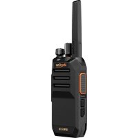
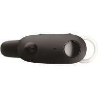
Introduction This user guide is written as per the highest tier model offered to the region. The following table describes ways to access features for your radio. Table 2: The Feature Access and Indications of the Radio Non-Keypad Radio Model Figure 1: R2 … mororoua Feature Access Programmable Button Feature Indication + Tone + _ LEDindicator *__ Voice Announcement or Text-to-Speech [7 NOTE: To understand which feature is available with the Programmable Button, you can refer to the Programmable Buttons on page 17 topic.
Radio Care This section describes the basic handling precaution of the radio. Table 3: IP Specification IP Specification Description IP55 Allows your radio to withstand low-pressure water jets from any direction and protects your radio from limited dust ingress. + __Keep your radio clean and exposure to water should be avoided to help ensure proper functionality and performance. + To clean the exterior surfaces of the radio, use a diluted solution of mild dishwashing detergent and fresh water (for example, one teaspoon of detergent to one gallon of water). *__ These surfaces should be cleaned whenever a periodic visual inspection reveals the presence of smudges, grease, and/or grime. CAUTION: The effects of certain chemicals and their vapors can have harmful results on certain plastics. Avoid using aerosol sprays, tuner cleaners, and other chemicals. + When cleaning your radio, do not use a high-pressure jet spray on radio as this may cause water to leak into your radio.
MN009532A01-AA Getting Started Getting Started This chapter provides instructions on how to prepare your radio for use.
Charging the Battery Your radio is powered by a Nickel Metal-Hydride (NiMH) or Lithium-lon (Li-lon) battery. Prerequisites: Turn off your radio when charging. Procedure: + Charge your battery only in non-hazardous areas. After battery is charged, allow your radio to rest for at least 3 minutes. +__ To comply with warranty terms and avoid damage, charge the battery using a Motorola Solutions authorized charger as described in the charger user guide. +__ Charge a new battery 14 to 16 hours before initial use for best performance. Batteries charge best at room temperature.
Attaching the Battery Procedure: 1 Align the battery with the rails on the back of the radio. 2 Press the battery firmly, and slide upwards until the latch snaps into place. 3 Slide battery latch into lock position. Postrequisites: [7 NOTE: If the radio is attached with the wrong battery, your radio shows the following indications: + __ A low pitched warning tone sounds. + _ The red LED blinks. + _ The display shows Wrong Battery +__ Voice Announcement or Text-to-Speech sounds "Wrong Battery" if the Voice Announcement or Text-to-Speech is loaded by using CPS. If the radio is attached with an unsupported battery, your radio shows the following indications: *__ An alert tone sounds. + _ The display shows Unknown Battery. + _ Battery icon is disabled. The certification of the radio is voided if you attach a UL battery to an FM approved radio or vice versa. If your radio is attached with an unsupported or wrong battery, immediately swap with the correct battery.
Chapter 3: Getting Started
Removing the Battery Prerequisites: Ensure that your radio is turned off. Procedure: Move the battery latch into unlock position and hold, and slide the battery down and off the rails.
Attaching the Antenna Procedure: 1 Set the antenna in the receptacle. 2 Turnthe antenna clockwise. [27 NOTE: Fastening the antenna blocks water and dust from entering the radio. CAUTION: To prevent damages, replace the faulty antenna with only MOTOTRBO antennas.
Removing the Antenna Procedure: 1 Turn the antenna counterclockwise. 2 Remove the antenna from the receptacle.
Attaching the Belt Clip Procedure: 1 Align the grooves on the clip with the grooves on the battery. 2 Press the belt clip downward until you hear a click sound.
Removing the Belt Clip Procedure: Slide the clip upward and away from the radio.
Turning the Radio On Procedure: Turn the On/Off/Volume knob clockwise until a click sounds. If your radio is turned on, your radio shows the following indications:
+ __Atone sounds. [7 NOTE: If the Tones/Alerts function is disabled, no tone sounds. + _ The green LEDilluminates. [7 NOTE: If your radio fails to turn on although your battery is charged and properly attached, contact your dealer for assistance.
Turning the Radio Off Procedure: Turn the On/Off/Volume knob counterclockwise until a click sounds.
Adjusting the Volume Procedure: 1 Perform one of the following actions: + _ Toincrease the volume, turn the On/Off/Volume knob clockwise. + To decrease the volume, turn the On/Off/Volume knob counterclockwise. E NOTE: Your radio can be programmed to have a minimum volume offset where the volume level cannot be lowered past the programmed minimum volume.
Radio Overview Figure 2: Radio Overview Table 4: Callout Legend Label Name Description 1 Antenna Provides the needed RF amplification when transmitting or re- ceiving. Lanyard Feature Allows you to secure holster to the radio. Push-to-Talk (PTT) Allows you to execute voice operations (for example, Group Call button and Private Call). 4 1-Dot Programmable Programmable button of an assignable radio function. Feature button 5 2-Dot Programmable Programmable button of an assignable radio function. Feature button 6 Microphone Allows your voice to be sent when PTT or voice operations are activated.
Label Name Description 7 Speaker Outputs all tones and audio that are generated by the radio (for example, features like keypad tones and voice audio). LED Indicator Provides operating status. On/Off/Volume knob Allows you to turn the radio on or off and adjust volume. 10 Audio Jack with Dust Allows you to connect audio accessories to your radio. Cover 11 Data Port Allows your radio for data communication. 12 Charging Rail Provides guideline for the placement during charging. 13 Charging Contacts Charging point for the battery. 14 Battery Provides power source to your radio.Battery Latch 15 Belt Clip Slot Allows you to attach belt clip. 16 Channel Selector Allows you to select channel. knob
Programmable Buttons You can program the programmable buttons as shortcuts to the following radio functions through programming software. [7 NOTE: Contact your dealer for more information. Table 5: Assignable Radio Functions Function Description All Alert Tones Allows you to toggle all tones and alerts to on or off. Channel Announcement Allows you to play zone and channel announcement voice mes- sages in the current channel. Confirm Allow you to confirm a feature. Mic AGC Allows you to toggle the internal microphone automatic gain con- trol (AGC) to on or off. One Touch Access Allows you to direct access to the predefined call features. Voice Announcement Allows you to toggle the voice announcement to on or off.
LED Indications The LED Indicator shows the operational status of your radio. A qualified technician can permanently disable the LED indication by preprogramming it.
Table 6: LED Indications Indication Status Blinking Red + _ The radio has failed the self-test upon powering up. + The radio is receiving an emergency transmission. + The radio is transmitting in low battery state. *__ The radio has moved out of range if Auto-Range Transponder System is configured. Solid Yellow *_ The radio is monitoring a conventional channel. *__Indicates fair battery capacity when the programmed Battery Indicator button is pressed. Blinking Yellow *__ The radio has yet to respond to a Call Alert. *__ The radio has Flexible Receive List enabled. Double Blinking Yellow + The radio is actively searching for a new site. + _ The radio has yet to respond to a Group Call Alert. + _ The radio is locked. Solid Green + __ The radio is powering up. *_ The radio is transmitting. + __Indicates full battery capacity when the programmed Battery Indicator button is pressed. Blinking Green + The radio is receiving a call or data. + The radio is detecting activity over the air. Double Blinking Green The radio is receiving a privacy-enabled call or data.
MN009532A01-AA System Overview Chapter System Overview System overview explains what type of systems and modes available in the radio.
Conventional Analog and Digital Modes Each channel in your radio can be configured as a conventional analog or conventional digital channel. Certain features are unavailable when switching from digital to analog mode, whereas some are available in both. There are minor differences on how each feature works but they do not affect the performance of your radio.
IP Site Connect This feature allows your radio to extend conventional communication beyond the reach of a single site by connecting to different available sites by using an Internet Protocol (IP) network. When the radio moves out of range from one site and into the range of another, the radio connects to the repeater of the new site to send or receive calls or data transmissions. This is done either automatically or manually depending on your settings. In an automatic site search, the radio scans through all available sites when the signal from the current site is weak or when the radio is unable to detect any signal from the current site. The radio then locks on to the repeater with the strongest Received Signal Strength Indicator (RSS) value. In a manual site search, the radio searches for the next site in the roam list that is currently in range but which may not have the strongest signal and locks on to the repeater. [7 NOTE: Each channel can only have either Scan or Roam enabled, not both at the same time. Channels with this feature enabled can be added to a particular roam list. The radio searches the channels in the roam list during the automatic roam operation to locate the best site. À roam list supports a maximum of 16 channels, including the selected channel. [7 NOTE: You cannot manually add or delete an entry in the roam list. Contact your dealer for more information.
Chapter 6 : Zone and Channel Selections
Zone and Channel Selections A zone is a group of channels. You can program each channel with different features that support different groups of users. Table 7: Number of Supported Zones and Channels Zone Channels
Selecting Zones Procedure: Press the programmed Zone Toggjle button. Your radio shows the following indications: +__lf your radio is in Zone 2, a positive tone sounds. + If your radio is in Zone 1, a negative tone sounds. [? NOTE: For all Non-keypad radio, you are recommended to enable Voice Announcement feature for selecting zone. The Voice Announcement feature can only be enabled through CPS.
Selecting Channels Procedure: Turn the Channel Selector knob. Your radio switches to your preferred channel.
MN009532A01-AA Types of Radio Calls Types of Radio Calls There are several ways that you can make a call with your radio depending on the types of calls and system available on your radio. Table 8: Types of Radio Calls Call Type Description Group Call A Group Call is a point-to-multipoint call operation. Your radio must be configured as a member of the group for you to commu- nicate with each other. Broadcast Voice Call A Broadcast Voice Call is a one-way voice call from any user to an entire talkgroup. The Broadcast Call feature allows only the call initiating user to transmit to the talkgroup, while the recipients of the call cannot respond. Private Call A Private Call is a call from an individual radio to another individ- ual radio. You can set up a Private Call after performing a radio presence check or call immediately. All Call An All Call is a call from an individual radio to every radio on the site or every radio at a group of sites. This feature is used to make an important announcement. Unaddressed Call An Unaddressed Call is a group call to one of the 16 predefined group IDs. Open Voice Channel Mode An OVCM is a call from a radio that is not preconfigured to (OVCM) work in a particular system during a group or individual call. The OVCM group call supports broadcast calls. When a call is interrupted, you hear a continuous Talk Prohibit Tone. Releasing the PTT button allows you to receive the call. Channel Free Indication feature can be programmed on your radio by your dealer. If the Channel Free Indication feature is enabled, you hear a short alert tone when the recipient releases the PTT button, indicating the channel is free for you to respond. [7 NOTE: If you would like to make a 5-Tone Call, you are required to purchase for a Software License Key separately.
Making Calls on the Radio Procedure: 1 Perform one of the following actions based on the type of calls: Option Actions Making group calls, private calls, unad- a Select a channel with an active ID or dressed calls, or selective calls alias.
Chapter 7 : Types of Radio Calls
Option Actions b To call, press and hold the PTT button. c Wait for the Talk Permit Tone to end, and speak into the microphone. [7 NOTE: For Group Call, you are to wait for the PTT Sidetone to end, and speak into the micro- phone if enabled. d Tolisten, release the PTT button. Making broadcast calls, all calls, or a Select a channel with an active group ID OVCM calls or alias. b To call, press and hold the PTT button. If your radio does not detect voice activity for a predetermined period, the call ends.
Receiving and Responding to Calls on the Radio When you receive calls, your radio shows the following indications: + _ The green LED blinks. *__ Your radio unmutes and the incoming call sounds through the speaker. [7 NOTE: You cannot respond to a Broadcast Call or All Call. Procedure: 1 To respond, press and hold the PTT button. 2 Wait for the Talk Permit Tone to end, and speak into the microphone. [27 NOTE: For Group Call, wait for the PTT Sidetone to end, and speak into the microphone if enabled. 3 To listen, release the PTT button.
MN009532A01-AA Voice Interrupt Voice Interrupt Voice Interrupt allows your radio to end any ongoing calls. The Voice Interrupt feature uses the reverse channel signaling to interrupt any ongoing calls. You are allowed to make a voice transmission during the interruption. The Voice Interrupt feature improves the probability of delivering a new call to the recipients when a call is in progress. Voice Interrupt is accessible if this feature has been programmed in your radio. Contact your dealer for more information.
Enabling the Voice Interrupt Procedure: 1 Tointerrupt the transmission during an on-going call, press and hold the PTT button. 2 Wait for the Talk Permit Tone to end, and speak into the microphone.
Initiating Transmit Interrupt Procedure: To interrupt an ongoing call, perform one of the following actions: + _ Press the PTT button. + __ Press the Emergency button.
MN009532A01-AA Advanced Features Advanced Features This chapter explains the operations of the features available in your radio.
Analog Scrambling This analog-only feature prevents eavesdropping by unauthorized users on a channel. Your radio must have analog scrambling enabled on the channel to send and receive an analog scrambling-enabled transmission. On an analog scrambling-enabled channel, the radio is not able to receive clear or unscrambled transmissions. Your radio supports two analog scrambling codes that can be toggled by using the programmable button.
Setting the Analog Scrambling Procedure: Press the programmed Analog Scrambling button.
Auto-Range Transponder System The Auto-Range Transponder System (ARTS) is an analog-only feature designed to inform you when your radio is out-of-range of other ARTS-equipped radios. ARTS-equipped radios transmit or receive signals periodically to confirm that they are within range of each other. Your radio provides indications as follows: Table 9: Auto-Range Transponder System Indications Indication Description First-Time Alert + Atone sounds. ARTS-in-Range Alert + __Atone sounds, if programmed. ARTS-Out-of-Range Alert + __Atone sounds. + __ The Red LED rapidly blinks.
Call Alert Operation Call Alert paging enables you to alert the recipient to call you back when they are able to do so. This feature is applicable for subscriber aliases or IDs only.
Making Call Alerts Procedure: Press the programmed One Touch Access button. If the request is successful, a positive indicator tone sounds. If the request is unsuccessful, a negative indicator tone sounds.
Responding to Call Alerts When you receive a Call Alert, your radio shows the following indications: + __ A repetitive tone sounds. + _ The yellow LED blinks. Procedure: Respond to the caller with a Private Call by pressing the PTT button.
Call Indicator Settings This feature allows you to configure call or text message tones.
Escalert Mode Tone The radio can be programmed to continually alert, when a radio call remains unanswered. This is done by automatically increasing the alarm tone volume over time. This feature is known as Escalert.
Emergency Operation Emergency Alarms are used to indicate critical situations. You can initiate an Emergency Alarm at any time even when there is activity on the current channel. You can only assign one type of Emergency Mode to the Emergency button for each channel. Your radio supports the following Emergency Modes: Table 10: Emergency Modes Emergency Mode Description Emergency Alarm An Emergency Alarm is not a voice call. This alarm is an emergency notifi- cation sent to radios that are programmed to receive them. Emergency Alarm Your radio transmits an Emergency Alarm. When the Emergency Alarm With Call is acknowledged, the group of radios can communicate over the assigned emergency channel. Press and hold the PTT button to talk. Emergency Alarm Your radio transmits an Emergency Alarm. When the Emergency Alarm is With Voice to Follow acknowledged, your radio microphone is automatically activated which is
Emergency Mode Description known as Hot Mic. Hot Mic allows you to communicate with the group of radios without pressing the PTT button. [7 NOTE: + __Ifthe Emergency Cycle Mode is enabled, repetitions of Hot Mic and receiving period are made for a programmed dura- tion. + _If you press and hold the PTT button during the programmed Hot Mic receiving period, your radio proceeds to make a call and stops Hot Mic receiving period timer. Your radio remains in emergency mode. Once PTT button is released, Hot Mic receiving period timer restarts. + _Ifthe Emergency Alarm request fails, the radio does not retry to send the request, and enters the Hot Mic directly. Silent Emergency Your radio transmits an emergency notification without any audio or visual Alarm indicators. Silent Emergency Your radio transmits an emergency notification without any audio or visual Alarm with Call indicators. Your radio suppresses all audio and visual indicators of the emergency until you press and hold the PTT button to talk. Silent Emergency Your radio transmits an emergency notification without any audio or visual Alarm with Voice to indicators. When the Emergency Alarm is acknowledged, the Hot Mic is Follow activated. You can communicate with the group of radios without pressing the PTT button. [7 NOTE: The indicators only appear when you press the PTT but- ton. Your dealer can set the Emergency On or Off function and button-press duration of the Emergency button. Contact your dealer for more information. Your dealer can program the Emergency Search tone. When the tone is programmed, the Emergency Search tone sounds. The tone mutes when your radio transmits or receives voice, and stops when your radio exits Emergency mode.
Sending Emergency Alarms Procedure: Press the programmed Emergency On button. If the alarm is successfully sent, your radio shows the following indications: +__ The Emergency tone sounds. If the alarm is unsuccessful after all retries, your radio shows the following indications: +__A negative tone sounds.
Sending Emergency Alarms with Call Procedure: 1 Press the programmed Emergency On button. If the alarm is successfully sent, your radio shows the following indications: +_ The Emergency tone sounds. To call, press and hold the PTT button. 3 Wait for the Talk Permit Tone to end, and speak into the microphone. 4 Tolisten, release the PTT button. If your radio does not detect voice activity for a predetermined period, the call ends.
Sending Emergency Alarms with Voice to Follow Procedure: 1 Press the programmed Emergency On button. If the alarm is successfully sent, the Emergency tone sounds and Hot Mic is activated. 2 Speak into the microphone without pressing the PTT button. Your radio automatically stops transmitting when: +__ The cycling duration between hot mic and receiving calls expires if Emergency Cycle Mode is enabled. + The hot mic duration expires if Emergency Cycle Mode is disabled.
Reinitiating the Emergency Mode Procedure: 1 Perform one of the following actions: +. Change the channel while the radio is in Emergency mode.
E NOTE: You can reinitiate emergency mode only if you enable emergency alarm on the new channel. +__Press the programmed Emergency On button during an emergency initiation or transmission state. The radio exits the Emergency mode, and reinitiates Emergency.
Exiting the Emergency Mode Your radio automatically exits emergency mode when you are having the following scenarios: +__ An acknowledgment is received from the system (for emergency alarms only). + Allretries to send the alarm are exhausted. + Turning off your radio. When you turn on your radio, the emergency will not reinitiate automatically. +__ Change your current channel to a channel with no Emergency. Procedure: Press the programmed Emergency Off button. If you exited the Emergency successfully, your radio shows the following indications: + _ The tone ceases. + _ The red LED extinguishes.
Lone Worker This feature prompts an emergency if there is no user activity (button press or channel selector activation) for a predefined time. When there is no user activity for a predefined time, the radio prewarns you using an audio indicator once the inactivity timer expires. If there is no acknowledgment from you before the predefined reminder timer expires, the radio initiates an emergency condition as programmed by the dealer.
Multi-Site Control Your radio is able to search for sites and switch between sites when signal is weak or your radio is unable to detect any signal from the current site. When the signal is strong, the radio remains on the current site. Your radio can perform either one of the following site searches: + Automatic Site Search + Manual Site Search If the current channel is a multi-site channel with an attached roam list and is out of range, and the site is unlocked, your radio performs automatic site search.
Starting and Stopping Automatic Site Search Procedure: Press the programmed Site Lock On/Off button. If the radio finds a new site, your radio shows the following indications: + __Atone sounds. +__ The LED blinks yellow rapidly when the radio is actively searching for a new site.
+ _ The yellow LED turns off once the radio locks on to a site. If the radio fails to find a new site, your radio shows the following indications: + Atone sounds. + The LED turns off.
Enabling Manual Site Search Procedure: Press the programmed Manual Site Roam button. A tone sounds and the green LED blinks. If the radio finds a new site, your radio shows the following indications: + __A positive tone sounds. + The LED extinguishes. If the radio fails to find a new site, your radio shows the following indications: *__A negative tone sounds. + The LED extinguishes.
Monitor Feature The feature allows you to remotely activate the microphone of a target radio. You can use this feature to monitor any audible activity surrounding the target radio.
Monitoring Channels Procedure: 1 Press and hold the programmed Monitor button. Your radio shows the following indications: +. You hear the radio activity. + __ The yellow LED illuminates. To call, press and hold the PTT button. 3 To listen, release the PTT button.
Permanent Monitor The Permanent Monitor feature is used to continuously monitor a selected channel for activity.
Setting the Permanent Monitor Procedure: Press the programmed Permanent Monitor button. When your radio enters the mode, your radio shows the following indications: + __ An alert tone sounds. + _ The yellow LED illuminates. When your radio exits the mode, your radio shows the following indications: + __ An alert tone sounds. +__ The yellow LED extinguishes.
Scan Depending on the supported system available on your radio, your radio may have different behavior on Scan. Channel Scan Channel Scan is available for Other Systems. When you start a scan, your radio scans through the programmed scan list for the current channel looking for voice activity. If you are on a digital channel, and your radio locks onto an analog channel, your radio automatically switches from digital mode to analog mode during the call and the same behavior occurs if you are on analog channel. Table 11: Scan Methods Method Description Main Channel Scan (Manual) Your radio scans all the channels or groups in your scan list. When scanning, your radio may, depending on the settings, auto- matically start on the last scanned active channel or group, or on the channel where scan was initiated. Auto Scan (Automatic) Your radio automatically starts scanning when you select a chan- nel or group that has Auto Scan enabled. When you miss a call from a talkgroup or a channel that is in your scan list, you might be having the following situations: *__ Scan feature is not turned on. +__ Scan list member has been disabled through the menu. + _ You are already participating in a call. [7 NOTE: If your radio joins a call for a Zone Scan List member from a different Zone and Call Hang Timer expires before you are able to respond, in order to respond, you must navigate to the Zone and Channel of the Scan List Member and start a new call.
Setting the Scan Procedure: Press the programmed Scan button to start or stop the Scan. If scan is turned on, your radio shows the following indications: *__ A positive indicator tone sounds. + _ The yellow LED blinks. If scan is turned off, your radio shows the following indications: + __ A negative indicator tone sounds. + _ The LED extinguishes.
Scan Talkback The Talkback feature allows you to respond to a transmission while scanning. Depending on how you configure the Scan Talkback feature, you will see two different scenarios if you press the PTT button when your radio scans into a call from the selectable group scan list. Table 12: Scan Talkback Type Type Description Scan Talkback Disabled During an ongoing scanned call, if the PTT but- ton is pressed, the scanned call is terminated and a new call is launched. Scan Talkback Enabled During an ongoing scanned call, if the PTT but- ton is pressed, you can talkback to the scanned call. [2 NOTE: If you face the following scenarios: 1 Scaninto a call for a group that is not assigned to a channel position in the currently selected zone 2 Miss the Hang Time of the call. Perform the following actions: 1 Switch to the proper zone. 2 Select the channel position of the group to talk back to that group.
Nuisance Channels Nuisance Channel is a channel that generates unwanted call continually. You can temporarily remove the unwanted channel from the scan list and restore it back later on. This capability does not apply to the channel designated as the Selected Channel.
Deleting Nuisance Channels Prerequisites: Your radio is scanned into the Nuisance Channel. Procedure: 1 Press the programmed Nuisance Delete button until you hear a tone. 2 Release the programmed Nuisance Delete button.
Restoring Nuisance Channels Procedure: Perform one of the following actions: + __Restart your radio. + Turn off and then turn on the scan. +__ Change the channel using the Channel Selector knob.
Vote Scan Vote Scan provides wide coverage in areas with multiple base stations transmitting identical information on different analog channels. Your radio scans analog channels of multiple base stations, and performs a voting process to select the strongest received signal. During a vote scan, your radio shows the following indications: + _ The yellow LED blinks. +__ The display shows the Vote Scan icon.
Scan Lists You can create and assign individual channels or groups in Scan Lists. Your radio scans for voice activity by cycling through the channel or group sequence specified in the scan list for the current channel or group. Scan List also known as Receive Group List. Your radio can support up to 250 scan lists, with a maximum of 16 members in a list. Each scan list supports a mixture of analog and digital entries.
Text Messaging Your radio is able to send data, for example a text message to another radio.
Sending Quick Text Messages Procedure: To send a predefined Quick Text message to a predefined alias, press the programmed One Touch Access button. If your text message is successfully sent, your radio shows the following indications: + __A positive tone sounds. + The green LEDilluminates. If your text message fails to send, a negative tone sounds:
Rental Timer The Rental Timer feature allows the radio rental dealer to set the permitted rental period of your radio and automatically disable the radio beyond the duration specified on the timer. The radio can be programmed with a maximum rental period of 999 hours and a maximum rental period extension of 99 hours. The timer calculates the radio usage time and disables the radio when the usage time reaches the predetermined rental period. After the rental period expires, the radio ceases to function until the dealer resets the rental timer.
Rental Expiry Reminder Rental Expiry Reminder feature provides a reminder when the rental period is expiring. The radio provides an audio reminder of the timer expiry. This feature triggers the reminder up to 9 hours before expiry and hourly reminder. 9 hours or the predetermined reminder hours before expiry Voice Announcement sounds Alquiler Vence Pronto which means rental expiring soon, and repeats for every following hour. Voice Announcement sounds Rental Expiring Soon and repeats for every following hour. 2 hours before expiry Voice Announcement sounds Alquiler Vence Pronto two times and repeats for every following hour. Voice Announcement sounds Rental Expiring Soon two times and repeats for every following hour. 3 minutes before expiry Voice Announcement sounds A/quiler Vence Pronto two times for every remaining minute. Voice Announcement sounds Rental Expiring Soon two times for every remaining minute. Voice Announcement sounds Alquiler Vencido when the rental period expires. The radio turns into disabled state. Voice Announcement sounds Rental Expired and the radio turns into disabled state.
Extending the Rental Period The radio can be programmed with a maximum of 99 hours rental period extension. [7 NOTE: You can only extend the rental period once. Procedure: +__Press the Side Button 2 six times continuously. One of the scenario occurs: +__Ifextension is performed before the rental period expires, Voice Announcement sounds Periodo de Alquiler Extendido which means rental period extended. +__ If extension is performed before the rental period expires, Voice Announcement sounds Rental Period Extended. +__Ifextension is performed after the rental period expires, your radio restarts automatically.
apter 11 Utilities This chapter explains the operations of the utility functions available in your radio.
Checking the Battery Strength Procedure: Press the programmed Battery Indicator button. One of the following scenario occurs: + The LED lights up solid yellow indicating fair battery capacity. + _ The LED lights up solid green indicating full battery capacity.
Password Lock You can set a password to restrict access to your radio. Each time you turn on your radio, you must enter the password. Your radio supports a four-digit password input. Your radio is unable to receive calls in locked state. These buttons function as a numeric keypad when entering password: Channel Selector Knob Position 1-9: Number 1-9 Position 10: Number 10 Side Buttons Side Button 1 and 2: Number 1 and 2.
Accessing Radios with Password Procedure: 1 Enter your first digit from the four-digit password using the Channel Selector Knob. 2 Enter the remaining three digits of the password by pressing Side Button 1 or 2. If you enter the password correctly, the radio turns on. If you enter the wrong password after the first and second attempt, a continuous tone sounds. If you enter the wrong password after the third attempt, your radio shows the following indications: + Atone sounds. + __ The yellow LED double blinks.
+ Your radio enters into locked state for 15 minutes. [7 NOTE: You can repeat the steps to enter the password. You are given three attempts before your radio enters into a locked state for 15 minutes. Wait for 15 minutes and then repeat the steps. If you restart your radio during the locked state, the timer restarts.
Unlocking Radios in Locked State Procedure: 1 To unlock your radio in locked state, perform one of the following actions: Option Actions Unlocking Radios in Locked State if your a Wait for 15 minutes. radio is turned on : : : b Access the radio by following the steps in Accessing Radios with Password. Unlocking Radios in Locked State if your |a Turn on your radio. radio is turned off : [7 NOTE: Your radio restarts the 15 minutes timer for locked state. b Wait for 15 minutes. c Access the radio by following the steps in Accessing Radios with Password.
Setting Radio Tones/Alerts Procedure: Press the programmed All Tones/Alerts button. If the setting is successful, a positive indicator tone sounds. If the setting is unsuccessful, a negative indicator tone sounds.
Setting Power Levels Procedure: Press the programmed Power Level button to transmit to a longer or shorter distance. If the setting is successful, your radio shows the following indications: + __A positive indicator tone sounds. +__ Radio transmits at the desired power level. If the setting is unsuccessful, your radio shows the following indications: +__ A negative indicator tone sounds.
*__ Radio transmission remains unchanged.
Setting Squelch Levels Procedure: Press the programmed Squelch button. If the setting is successful, your radio is operating in tight squelch and a positive indicator tone sounds. If the setting is unsuccessful, your radio is operating in normal squelch and a negative indicator tone sounds.
Setting the Trill Enhancement You can enable this feature when you are speaking in a language that contains many words with alveolar trill (rolling "R") pronunciations. Procedure: Press the programmed Trill Enhancement button to toggle the feature on or off. If the setting is successful, a positive indicator tone sounds. If the setting is unsuccessful, a negative indicator tone sounds.
Setting the Voice Announcement Procedure: Press the programmed Voice Announcement button. If the setting is successful, a positive indicator tone sounds. If the setting is unsuccessful, a negative indicator tone sounds.
Talkaround This feature allows you to continue communicating when your repeater is non-operational, or when your radio is out of range from the repeater but within the talk range of other radios. The talkaround setting is retained even after powering down.
Toggling Between Repeater and Talkaround Mode Procedure: Press the programmed Repeater or Talkaround button to toggle between Repeater or Talkaround modes on your radio. A positive indicator tone sounds indicating the radio is in talkaround mode.
A negative indicator tone sounds indicating the radio is in repeater mode.
Voice Operating Transmission Voice Operating Transmission (VOX) allows you to initiate hands-free voice-activated calls on a programmed channel. When your VOX-capable accessory detects voice, your radio automatically transmits for a programmed period. [7 NOTE: This feature is not applicable in Citizen Band channels that are in the same frequency. Contact your dealer or administrator for more information.
Setting the Voice Operating Transmission Procedure: Press the programmed VOX button to toggle the feature on or off.
Privacy This feature prevents eavesdropping by unauthorized users on a channel by the use of a software- based scrambling solution. The signaling and user identification portions of a transmission are clear. Your radio must have privacy enabled on the channel to send a privacy-enabled transmission, although this is not a requirement for receiving a transmission. Some radio models may not offer Privacy feature, or may have different configuration. Contact your dealer for more information. [7 NOTE: Only one type of privacy can be assigned at a time. This feature is not applicable in Citizens Band channels that are in the same frequency. The following table describes the type of privacy and the settings that appear on your radio. Table 13: Privacy Types and Settings Type Setting Basic Privacy Privacy
Privacy-Enabled Calls Your radio must have the Privacy feature enabled for the currently selected channel position to send a privacy-enabled transmission. While on a privacy-enabled channel, the radio is still able to receive clear transmissions. When privacy is enabled for the currently selected channel position, all voice transmission made by your radio is scrambled. The calls include Group Call, Multigroup Call, talkback during scanned calls, Site AIl Call, Emergency Call, and Private Call. Only receiving radios with the same Key Value and Key ID as your radio can unscramble the transmission.
To unscramble privacy-enabled call or data transmission, your radio must be programmed to have the same type of Privacy Key as the transmitting radio. If your radio receives a scrambled call that is of a different Privacy Key, you hear a garbled transmission.
MN009532A01-AA Authorized Accessories List Authorized Accessories List Motorola Solutions provides a list of accessories to improve the productivity of your radio. Table 14: Antenna Part Number Description PMAD4116_ VHF, 144-165 MHz, Helical Antenna PMAD4117_ VHF, 136-155 MHz, Helical Antenna PMAD4118_ VHF, 152-174 MHz, Helical Antenna PMAD4119_ VHF, 136-148 MHz, Stubby Antenna PMAD4120_ VHF, 146-160 MHz, Stubby Antenna PMAD4121_ VHF, 160-174 MHz, Stubby Antenna PMAD4147_ VHF, 136-174 MHz, Whip Antenna 20 cm PMAE4069_ UHF, 403-450 MHz, Stubby Antenna PMAE4070_ UHF, 440-490 MHz, Stubby Antenna PMAE4079_ UHF, 400-527 MHz, Slim Whip Antenna Table 15: Batteries Part Number Description PMNN4598_ Li-lon Battery IP55 2300T PMNN4600_ Li-lon Battery IP55 2100T Table 16: Cables Part Number Description PMKN4128_ Programming Cable USB Table 17: Carry Devices Part Number Description HLN9714_ 2.5 in. Spring Belt Clip HLN9844_ 2 in. Spring Action Belt Clip HLN9985_ Weatherproof Baggie HLN6602_ Universal Chest Pack NTN5243_ Adjustable Nylon Carrying Strap PMLN4651_ Belt Clip for 2 in. Belt Width PMLN5610_ 2.5 in. Replacement Leather Swivel Belt Loop PMLN5611_ 3 in. Replacement Leather Swivel Belt Loop
Chapter 12 : Authorized Accessories List
Chapter 12 : Authorized Accessories List
Part Number Description PS000037A04 Power Supply Adaptor, Power-wall Cube , AC, DC, Switch- mode, 14 W, 207 V-253 V, Argentina Plug PS000037A05 Power Supply Adaptor, Power-wall Cube , AC, DC, Switch- mode, 14 W, 207 V-253 V, China Plug PS000037A06 Power Supply Adaptor, Power-wall Cube , AC, DC, Switch- mode, 14 W, 207 V-253 V, Korea Plug WPLN4137BR Single Unit Charger (Non-CEC) Base Table 19: Earbuds and Earpieces Part Number Description PMLN6531_ Ear Receiver with In-Line Microphone/ PTT/VOX Switch (Mag One) PMLN6532_ Swivel Earpiece with In-Line Microphone and PTT PMLN6533_ Earset with combined microphone and PTT PMLN6534_ Earbud with In-Line Microphone/PTT/VOX Switch (Mag One) PMLN6535_ D-Style Earpiece with Microphone/PTT PMLN8502_ Accessory Retainer Clip Table 20: Headsets and Headset Accessories Part Number Description AY000308A01 Accessory Kit Headset Cable for Digital GP300 AY000309A01 Accessory Kit.Mesh Head Strap AY000310A01 Accessory Kit, Microphone Windscreen with Retaining O-Ring (Quanitity 5 per Bag) AY000311A01 Accessory Kit,Gel Ear Seal with Mesh and O-Ring (Quantity 2 per Bag) AY000312A01 Accessory Kit, Headset Left Microphone Boom Assembly (Standard) AY000313A01 Accessory Kit, Headset Right Microphone Boom Assembly PMLN6538_ Lightweight Headset with Swivel Boom Microphone PMLN6542_ MagOne Ultra-Lite Headset, behind-the-head, adjustable with Boom Microphone and In-line PTT PMLN6854_ Heavy Duty Headset, Noise Canceling Boom Mic Headset PMLN7468_ Medium Weight Over-the-Head Dual Muff Headset REX4648_ Replacement Foam Earpad and Windscreen Kit Table 21: Remote Speaker Microphones Part Number Description PMMN4013_ Windporting Remote Speaker Microphone with 3.5mm audio Jack (IP54)
Chapter 12 : Authorized Accessories List
Part Number Description PMMNA4029_ Windporting Remote Speaker Microphone, Submersible (IP57) PMMN4148_ RM110 Remote Speaker Microphone, with 3.5mm Audio Jack, IP55 PMMN4149_ RM110 Remote Speaker Microphone, without 3.5mm Audio Jack, IP55 PMLN8121_ Low Profile Swivel Clip PMLN8122_ Replacement Dust Cover for RSM (Pack of 10) Table 22: Surveillance Accessories Part Number Description AARLN4885B & MDRLN4885B Receive-Only Covered Earbud with Coiled Cord PMLN4620_ Receive-Only D-Shell Earpiece PMLN6445_ 2-Wire Surveillance Kit with Translucent Tube, Beige PMLN6530_ 2-Wire Surveillance Kit with Translucent Tube, Black PMLN7396_ Receive -Only Adjustable D-Style with Standard 3.5mm Jack PMLN7560_ Receive-Only Earpiece with Translucent Tube PMLN8120_ Receive-Only XL Clear Tube Earpiece, 3.5mm Jack
RLN4941A & MDRLN4941A
Receive-Only Earpiece with Translucent Tube and Rubber Eartip RLN4760_ Small Custom Earpiece for Surveillance Kits, Right Ear RLN4761_ Medium Custom Earpiece for Surveillance Kits, Right Ear RLN4762_ Large Custom Earpiece for Surveillance Kits, Right Ear RLN4763_ Small Custom Earpiece for Surveillance Kits, Left Ear RLN4764_ Medium Custom Earpiece for Surveillance Kits, Left Ear RLN4765_ Large Custom Earpiece for Surveillance Kits, Left Ear RLN6242_ Replacement Quick Disconnect Translucent Tube with One Clear Rubber Eartip RLN6282_ Replace Rubber Ear Tips for RLN6242_