CVE-15 - Speaker Cerwin-Vega - Free user manual and instructions
Find the device manual for free CVE-15 Cerwin-Vega in PDF.
User questions about CVE-15 Cerwin-Vega
0 question about this device. Answer the ones you know or ask your own.
Ask a new question about this device
Download the instructions for your Speaker in PDF format for free! Find your manual CVE-15 - Cerwin-Vega and take your electronic device back in hand. On this page are published all the documents necessary for the use of your device. CVE-15 by Cerwin-Vega.
USER MANUAL CVE-15 Cerwin-Vega
CVE Powered Speaker Series
Quick Start Guide
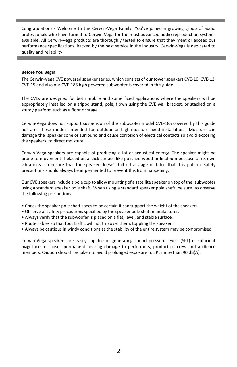
Congratulations - Welcome to the Cerwin-Vega Family! You've joined a growing group of audio professionals who have turned to Cerwin-Vega for the most advanced audio reproduction systems available. All Cerwin-Vega products are thoroughly tested to ensure that they meet or exceed our performance specifications. Backed by the best service in the industry, Cerwin-Vega is dedicated to quality and reliability.
Before You Begin
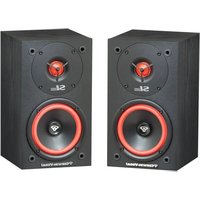
The Cerwin-Vega CVE powered speaker series, which consists of our tower speakers CVE-10, CVE-12, CVE-15 and also our CVE-18S high powered subwoofer is covered in this guide.
The CVEs are designed for both mobile and some fixed applications where the speakers will be appropriately installed on a tripod stand, pole, flown using the CVE wall bracket, or stacked on a sturdy platform such as a floor or stage.
Cerwin-Vega does not support suspension of the subwoofer model CVE-18S covered by this guide nor are these models intended for outdoor or high-moisture fixed installations. Moisture can damage the speaker cone or surround and cause corrosion of electrical contacts so avoid exposing the speakers to direct moisture.
Cerwin-Vega speakers are capable of producing a lot of acoustical energy. The speaker might be prone to movement if placed on a slick surface like polished wood or linoleum because of its own vibrations. To ensure that the speaker doesn't fall off a stage or table that it is put on, safety precautions should always be implemented to prevent this from happening.
Our CVE speakers include a pole cup to allow mounting of a satellite speaker on top of the subwoofer using a standard speaker pole shaft. When using a standard speaker pole shaft, be sure to observe the following precautions:
- Check the speaker pole shaft specs to be certain it can support the weight of the speakers.
- Observe all safety precautions specified by the speaker pole shaft manufacturer.
- Always verify that the subwoofer is placed on a flat, level, and stable surface.
- Route cables so that foot traffic will not trip over them, toppling the speaker.
- Always be cautious in windy conditions as the stability of the entire system may be compromised.
Cerwin-Vega speakers are easily capable of generating sound pressure levels (SPL) of sufficient magnitude to cause permanent hearing damage to performers, production crew and audience members. Caution should be taken to avoid prolonged exposure to SPL more than 90 dB(A).
DECLARATION OF CONFORMITY
FCC Statement :

FCC ID: 2BCMC-GC253367
IC:28474-AAAPL01
This equipment has been tested and found to comply with the limits for a Class B digital device, pursuant to part 15 of the FCC Rules. These limits are designed to provide reasonable protection against harmful interference in a residential installation. This equipment generates uses and can radiate radio frequency energy and, if not installed and used in accordance with the instructions, may cause harmful interference to radio communications. However, there is no guarantee that interference will not occur in a particular installation. If this equipment does cause harmful interference to radio or television reception, which can be determined by turning the equipment off and on, the user is encouraged to try to correct the interference by one or more of the following measures:
—Reorient or relocate the receiving antenna.
Increase the separation between the equipment and receiver.
—Connect the equipment into an outlet on a circuit different from that to which the receiver is connected.
Consult the dealer or an experienced radio/TV technician for help.
Any changes or modifications not expressly approved by the party responsible for compliance could void the user's authority to operate the equipment.
ISED Statement :
This device contains license-exempt transmitter(s)/receiver(s) that comply with Innovation, Science and Economic Development Canada's license-exempt RSS(s). Operation is subject to the following two conditions:
(1) This device may not cause interference.
(2) This device must accept any interference, including interference that may cause undesired operation of the device.
This transmitter must not be co-located or operating in conjunction with any other antenna or transmitter. This equipment should be installed and operated with a minimum distance of 20 centimeters between the radiator and your body.
Warning: The apparatus with CLASS I construction shall be connected to a MAINS socket outlet with a protective earthing connection.
Class I pluggable equipment type A intended for connection to other equipment or a network shall, if safety relies on connection to reliable earthing or if surge suppressors are connected between the network terminals and accessible parts, have a marking stating that the equipment shall be connected to an earthed mains socket-outlet.
IMPORTANT SAFETY INFORMATION
SAFETY INSTRUCTIONS
-
Read instructions - All the safety and operating instructions should be read before the product is operated.
-
Retain instructions - The safety and operating instructions should be retained for future reference.
-
Heed Warnings - All warnings on the product and in the operating instructions should be adhered to.
-
Follow Instructions - All operating and use instructions should be followed.
-
Cleaning - Unplug this product from the wall outlet before cleaning. Do not use liquid cleaners or aerosol cleaners. Use a damp cloth for cleaning.
-
Attachments - Do not use attachments not recommended by the product manufacturer as they may cause hazards.
-
Water and Moisture - Do not use this product near water-for example, near a bath tub, wash bowl, kitchen sink, or laundry tub; in a wet basement; or near a swimming pool; and the like.
-
Accessories - Do not place this product on an unstable cart, stand, tripod, bracket, or table. The product may fall, causing serious injury to a child or adult and serious damage to the product. Use only with a cart, stand, tripod, bracket, or table recommended by the manufacturer, or sold with the product. Any mounting of the product should follow the manufacturer's instructions, and should use a mounting accessory recommended by the manufacturer.
-
Cart - A product and cart combination should be moved with care. Quick stops, excessive force, and uneven surfaces may cause the product and cart combination to overturn.
-
Ventilation - Slots and openings in the cabinet are provided for ventilation to ensure reliable operation of the product and to protect it from overheating. These openings must not be blocked or covered. The openings should never be blocked by placing the product on a bed, sofa, rug, or another similar surface. This product should not be placed in a built-in installation such as a bookcase or rack unless proper ventilation is provided or the manufacturer's instructions have been adhered to.
-
Power Sources - This product should be operated only from the type of power source indicated on the marking label and connected to a MAINS socket outlet with a protective earthing connection. If you are not sure of the type of power supply to your home, consult your product dealer or local power company.
-
Power-Cord Protection - Power-supply cords should be routed so that they are not likely to be walked on or pinched by items placed upon or against them, paying attention to cords at plugs, convenience receptacles, and the point where they exit from the product.
-
Mains Plug - Where the mains plug or an appliance coupler is used as the disconnect device, the disconnect device shall remain readily operable.
-
Lightning - For added protection for this product during a lightning storm, or when it is left unattended and unused for long periods of time, unplug it from the wall outlet and disconnect the antenna or cable system. This will prevent damage to the product due to lightning and power-line surges.
-
Overloading - Do not overload wall outlets, extension cords, or integral convenience receptacles as this can result in a risk of fire or electric shock.
-
Flame Sources - No naked flame sources, such as lighted candles, should be placed on the product.
-
Object and Liquid Entry - Never push objects of any kind into this product through openings as they may touch dangerous voltage points or short-out parts that could result in a fire or electric shock. Never spill liquid of any kind on the product.
-
Loudspeakers - Excessive sound pressure from loudspeakers can cause hearing loss.
-
Damage Requiring Service - Unplug this product from the wall outlet and refer servicing to qualified service personnel under the following conditions:
a. When the power-supply cord or plug is damaged.
b. If liquid has been spilled, or objects have fallen into the product.
c. If the product has been exposed to rain or water.
d. If the product has been dropped or damaged in any way.
e.When the product exhibits a distinct change in performance- this indicates a need for service.
f. If the product does not operate normally by following the operating instructions. Adjust only those controls that are covered by the operating instructions as an improper adjustment of other controls may result in damage and will often require extensive work by a qualified technician to restore the product to its normal operation.
- Replacement Parts When replacement parts are required, be sure the service technician has used replacement parts specified by the manufacturer or have the same characteristics as the original part. Unauthorized substitutions may result in fire, electric shock, or other hazards.
- Safety Check - Upon completion of any service or repairs to this product, ask the service technician to perform safety checks to determine that the product is in proper operating condition. The use of apparatus in tropical and/or moderate climates.
WARNING
The lightning flash with arrowhead symbol, within an equilateral triangle, is intended to alert the user to the presence of uninsulated "dangerous voltage" within the product's enclosure that may be of sufficient magnitude to constitute a risk of electric shock to persons
The exclamation point within an equilateral triangle is intended to alert the user to the presence of important operating and maintenance (servicing) instructions in the literature accompanying the appliance.


THE EQUIPMENT MUST BE CONNECTED TO AN EARTHED MAINS SOCKET-OUTLET.
CAUTION REGARDING PLACEMENT
To maintain proper ventilation, be sure to leave a space around the unit (from the largest outer dimensions including projections) than is equal to, or greater than shown below.
Top, Bottom, Front, Rear, Left, Right Sides: 10 cm
CAUTION - Changes or modifications to this equipment not expressly approved by Cerwin-Vega for compliance could void the user's authority to operate this equipment.
CAUTION - To prevent electric shock, match wide blade of plug to wide slot, fully insert.
CAUTION - Marking and rating plate can be found at the rear panel of the apparatus.
WARNING - To reduce the risk of fire or electric shock, do not expose this apparatus to rain or moisture.
The apparatus shall not be exposed to dripping or splashing and that no objects filled with liquids, such as vases, shall be placed on apparatus.
Mains plug is used as disconnect device and it should remain readily operable during intended use. To disconnect the apparatus from the mains completely, the mains plug should be disconnected from the mains socket outlet completely.
CAUTION - An appliance with a protective earth terminal should
be connected to a mains outlet with a protective earth connection.
IF IN DOUBT CONSULT A COMPETENT ELECTRICIAN. NOTES ON ENVIRONMENTAL PROTECTION
At the end of its useful life, this product must not be disposed of with regular household waste but must be returned to a collection point for the recycling of electrical and electronic equipment. The symbol on the product, user's manual and packaging point this out.
The materials can be reused in accordance with their markings. Through re-use, recycling of raw materials, or other forms of recycling of old products, you are making an important contribution to the protection of our environment.
Your local administrative office can advise you of the responsible waste disposal point.

Note: CVE letter of CE conformity available via email: ra2@dat-cvm.com
Quick Set-Up
The steps below provide a quick reference on how to setup and use a single loudspeaker. A typical setup will follow the same basic steps.
| STEP 1 | ✓ Make sure the loudspeaker is unplugged. ✓ Be sure the power switch is set to the OFF position. ✓ Turn the LEVEL knob to the lowest level (fully counter-clockwise). |
| STEP 2 | ✓ Place the loudspeaker in the ideal location. ✓ Connect the source audio equipment OUTPUT to the loudspeaker INPUT. Be sure the source equipment is powered on and set to a normal output level. |
| STEP 3 | ✓ Connect the power cord to the loudspeaker AC power outlet. ✓ Set the POWER switch to the ON position and verify that the DSP MODE LED indicator is illuminated. ✓ Slowly turn the LEVEL knob clockwise until the sound output is at the desired level. If there is no sound, check to make sure the source equipment is providing audio output. |
| NOTE | When you are done using the loudspeaker, set the POWER switch to OFF BEFORE removing any cables and turning off the source audio equipment. |
Loudspeaker placement
- Never point a microphone directly at a loudspeaker, as this will result in extreme feedback (unwanted sound). Be sure the loudspeaker is placed away from the front of the microphone or directly behind the microphone when in a floor monitor position.
- When used with turntables, carefully place the loudspeaker so that any vibrations do not interfere with the turntable performance and functionality.
- Avoid placing the loudspeaker in the corners or along the walls of a room. This will increase the low-frequency content of the audio and may result in a muddy and incoherent sound reproduction.
- Avoid placing the speakers directly on a hollow stage. It is better to place the loudspeakers on tripod stands or a sturdy table.
- The loudspeaker should be placed two to four feet above the ear level of the audience since the human body can absorb sound especially at high frequencies. This will make sure the entire audience can hear the sound system with the best possible clarity.
mode is a great starting point for mixing live events.
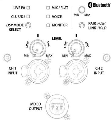
CVE-10/12/15 Rear Panel
(A) DSP MODE SELECT This mode selection button allows you to toggle between our 5 EQ presets. Listen to each of these and determine what is best for you.
LIVE PA - Best used for live music sound reinforcement, it balances and softens frequencies that can dominate and feedback in a live mix.
CLUB/DJ - This mode adds definition to the high and low frequencies, it is primarily used for playback of EDM/Pop/Hip Hop/etc. music.
MIX / FLAT - A well balanced overall speaker response with deeper low-end extension. This
VOICE - This mode enhances vocal clarity and is best used when using a common dynamic microphone connected directly into one of the CH inputs.
MOTOR - Use this mode when using the system as a stage monitor with a microphone, it will balance and soften frequencies that are prone to feedback in a monitor mix.
(B) BLUETOOTH
We have included True Wireless Stereo (TWS) Bluetooth connectivity in the CVE. To PAIR with one unit push the pair button once. The Blue light will begin flashing and your unit will pop up in your Bluetooth devices list. To LINK 2 devices together in stereo you push and hold the first unit until it begins flashing orange. Then push and hold the other unit's button until it flashes orange. After 10 seconds the units will LINK together into a Stereo pair. Once paired you can toggle between Stereo & MONO by double tapping the pairing button while audio is playing.
Note: you cannot PAIR, UN-PAIR, or LINK units while audio is playing. See Manual & Application Guide for more details.
C INPUT 1 & INPUT 2
These are Balanced Combo Inputs allowing for balanced XLR/TRS cables to be inserted as LINE & MIC levels.
(D) LEVEL KNOBS
Channel 1 & 2 LEVEL knobs adjust the gain level on the respective input signal. The LEVEL is designed to be used for a LINE level input as well as a MIC level input. Full counter-clockwise position (MIN) to straight up (into the detent) is adjustment for LINE levels. Whereas from straight up to full clockwise (MAX) position adjusts for MIC levels. The Bluetooth level knob is provided so that you can adjust the level of the Bluetooth signals to match your other inputs as needed.
E MIX OUTPUT
This connection is designed to provide an output which combines all channels including Bluetooth together for connecting to another powered speaker or a recording device. This output is affected by changes to each channels LEVEL knob.
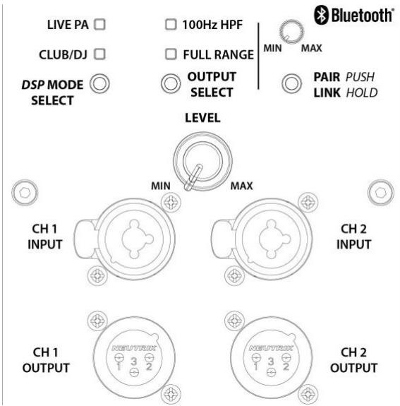
CVE-18s Rear Panel
(A) DSP MODE SELECT This mode selection button allows you to toggle between our 2 EQ presets. Listen to each of these and determine what is best for you.
LIVE PA - Best used for live music sound reinforcement, it has a more balanced deeper low-end response.
CLUB/DJ - This mode adds definition and punch to sub frequencies, it is primarily used for playback of EDM/Pop/Hip Hop/etc. music.
(B) OUTPUT MODE SELECT
This mode selection button
allows you to toggle between a 100 Hz High Pass Filter on the outputs; providing a crossover to top boxes or leave the output jack's full range.
(c) BLUETOOTH
We have included True Wireless Stereo (TWS) Bluetooth connectivity in the CVE. To PAIR with one unit push the pair button once. The Blue light will begin flashing and your unit will pop up in your Bluetooth devices list. To LINK 2 devices together in stereo you push and hold the first unit until it begins flashing orange. Then push and hold the other unit's button until it flashes orange. After 10 seconds the units will LINK together into a Stereo pair. Once paired you can toggle between STEREO & MONO by double tapping the pairing button while audio is playing.
Note: you cannot PAIR, UN-PAIR, or LINK units while audio is playing.
(D) INPUT 1 & INPUT 2
These are Balanced Combo Inputs allowing for balanced XLR/TRS LINE levels.
(E) LEVEL KNOB
The LEVEL adjusts the output level of the subwoofoers for all channels equally. The Bluetooth level knob is provided so that you can adjust the level of the Bluetooth signals to match your other inputs as needed.
(F) OUTPUTS 1 & 2
This connection is designed to provide an output which combines each input channel with the incoming Bluetooth signal respectively, for connecting to another powered speaker or a recording device. This output is not affected by changes to the LEVEL knob.
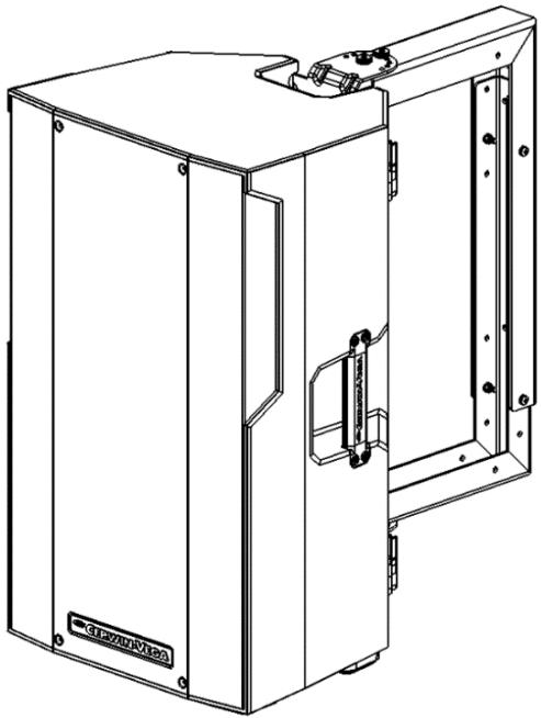
Optional WALL/CEILING MOUNT
(wall/ceiling kit is sold separately)
CVE SERIES are designed to be:
- Floor standing.
- When a subwoofer and the tower are used together, these can be mounted vertically on top of each other via the built in pole mount socket in both speakers that accepts a standard speaker pole that is sold separately.
- Cabinets are engineered to accept our Wall/Ceiling mount kit that is sold separately.
SPECS
| CVE-10* | CVE-12* | CVE-15" | CVE-18s" | |
| Power Rating | 1000 | 1000 | 1000 | 1000 |
| Amplifier Class | D | D | D | D |
| Frequency Response (+/- 3dB) | 65Hz - 18kHz | 55Hz - 18kHz | 47Hz - 18kHz | 35Hz -225Hz |
| Frequency Range (+/- 10d8) | 60Hz - 20kHz | 50Hz - 20kHz | 42Hz - 20kHz | 30Hz -250Hz |
| Max SPL | 124 | 126 | 128 | 126 |
| HF Driver | 1" | 1" | 1" | N/A |
| LF Driver | 10" | 12" | 15" | 18" |
| Dispersion | 90° x 60° | 90° x 60° | 90° x 60° | N/A |
| Input/Output | (2) Combo XLR/TRS Inputs | (2) Combo XLR/TRS Inputs | (2) Combo XLR/TRS Inputs | (2) Combo XLR/TRS Inputs |
| (1) Combo XLR OUTPUT | (1) Combo XLR OUTPUT | (1) Combo XLR OUTPUT | (2) Combo XLR OUTPUT | |
| Switches | EQ Mode Select (5 modes) | EQ Mode Select (5 modes) | EQ Mode Select (5 modes) | EQ Mode Select (2 modes) |
| Bluetooth Pair/Link | Bluetooth Pair/Link | Bluetooth Pair/Link | Bluetooth Pair/Link Output Mode Select | |
| Enclosure | Polymer | Polymer | Polymer | Plywood |
| Finish | Standard | Standard | Standard | Paint |
| Dimensions (h x w x d) | 558mm x 328mm x 288mm | 619mm x 358mm x 320mm | 694mm x 425mm x 380mm | 620mm x 533mm x 648mm |
| Weight (Lbs.) | 33 | 35 | 39 | 60 |
| Weight (Kg) | 15 | 15.9 | 17.7 | 27.2 |
Note: the CVEs were tested at the highest working environment temperature and altitude (45°/2000m).
Bluetooth version: 5.3
- Bluetooth transmitter frequency range: 2402 MHz - 2480 MHz
- Bluetooth transmitter power: <11 dBm (EIRP)
*Specifications & appearance subject to Change
USA WARRANTY INFORMATION
Cerwin-Vega, Inc offers a 1-year warranty on the CVE models under the following conditions.
The warranty is valid for the original retail purchaser only and is not transferable. To be eligible for warranty coverage, the product must be registered within 15 days from the date shown on the sales receipt.
To obtain warranty repair work:
- Contact Cerwin-Vega customer service and provide them with the product's serial number and proof of purchase.
- If the product is determined to be covered under warranty by Cerwin-Vega, Inc then Cerwin-Vega will issue an authorized RMA number.
- Customer must ship the product to the authorized Cerwin-Vega service center at the address provided by customer service representative.
- The customer is responsible for all shipping costs unless stated otherwise.
- Cerwin-Vega will repair or replace the product at its sole discretion.
- If the product is repaired, it will be shipped back to the customer free of charge.
- If the product is replaced, the customer will be responsible for shipping the old product back to Cerwin-Vega before the replacement product will be sent to the customer.
Please note that any non-authorized returns sent to Cerwin-Vega, Inc will be refused. This means that you must contact Cerwin-Vega customer service first to seek any potential warranty work and get an authorized RMA number before you attempt to ship the product to the address provided by the Cerwin-Vega, Inc customer service representative. Shipping the product is the customers responsibility.
Here are some additional things to keep in mind when filing a warranty claim:
- You must have registered your product within 15 days from the sales receipt date.
The warranty period is one year from the date of purchase once registered - The warranty does not cover damage caused by abuse, accident, misuse, or neglect, unauthorized modifications or repairs made outside the authorized customer service repair centers.
You must provide proof of purchase (copy of original sales receipt) to make a warranty claim.
INTERNATIONAL WARRANTY INFORMATION:
Cerwin-Vega does not offer a warranty of any kind for products sold outside the USA.
Please contact your dealer from whom you purchased the product for all warranty claims and service or other inquires.
Cerwin-Vega,Inc
USA Customer Service:
Contact: 1-213-261-4161
Email: ra2@dat-cvm.com