
LDIMA120 - Amplifier LD Systems - Free user manual and instructions
Find the device manual for free LDIMA120 LD Systems in PDF.
| Product Type | Professional Audio Amplifier |
| Brand | LD Systems |
| Model | LDIMA120 |
| Category | Amplifier |
| Intended Use | Professional audio installations (non-domestic) |
| Protection Class | Class 1 or 2 depending on model (protective conductor must be connected) |
| Power Supply | Mains, voltage and frequency according to indications on the device |
| Fuse | Type printed on the device, do not bypass |
| Output Power | 120 W (indicative based on model) |
| Connectivity | Signal inputs and outputs, Power Out (maximum output current to be observed) |
| Ventilation | Do not obstruct ventilation openings |
| Minimum Safety Distance | 0.3 m from flammable materials |
| Ambient Temperature | Ambient temperature before commissioning after temperature variations |
| IP Protection Rating | According to specifications, not suitable for tropical climates or above 2000 m |
| Mounting Height | Less than 5 m unless otherwise specified |
| Maintenance and Cleaning | Regular dusting, do not use abrasive products |
| Spare Parts and Repairability | No user-serviceable parts, intervention by qualified personnel only |
| Environment | Do not dispose of with household waste, follow the WEEE directive |
| Warranty | Manufacturer warranty according to Adam Hall GmbH conditions |
| General Information | Complete manual available at www.ld-systems.com |
Frequently Asked Questions - LDIMA120 LD Systems
User questions about LDIMA120 LD Systems
0 question about this device. Answer the ones you know or ask your own.
Ask a new question about this device
Download the instructions for your Amplifier in PDF format for free! Find your manual LDIMA120 - LD Systems and take your electronic device back in hand. On this page are published all the documents necessary for the use of your device. LDIMA120 by LD Systems.
USER MANUAL LDIMA120 LD Systems
INFORMATION ON THIS USER MANUAL 3
PROPERUSE 3
DEFINITIONS AND SYMBOL EXPLANATIONS 3
SAFETY INSTRUCTIONS 4
INSTRUCTIONS FOR INDOOR INSTALLATION
EQUIPMENT 7
PACKAGING CONTENT 8
INTRODUCTION 8
CONNECTIONS, OPERATING AND DISPLAY ELEMENTS 10
CONNECTION EXAMPLES 16
TERMINAL BLOCK CONNECTIONS 17
JUMPER FOR EMERGENCY SIGNAL TO AUX OUT 18
RACK MOUNTING 19
UNDER-TABLE MOUNTING 20
CARE, MAINTENANCE AND REPAIR 21
TECHNICAL DATA 22
DISPOSAL 26
MANUFACTURER'S DECLARATIONS 27
DEUTSCH
Scan this QR Code to get to the download section of IMA120/240. Here you can get the complete User manual in the following languages: EN, DE, FR, ES, PL, IT
www.Id-systems.com/LDIMA120-downloads
www.Id-systems.com/LDIMA240-downloads
ENGLISH
YOU HAVE MADE THE RIGHT CHOICE!
This device has been developed and manufactured to the highest quality standards to ensure many years of problem-free operation. This is what LD Systems stands for with its name and many years of experience as a manufacturer of high-quality audio products. Please read these operating instructions carefully so that you can quickly get the most out of your new LD Systems product.
You can find more information about LD Systems on our website WWW.LD-SYSTEMS.COM
INFORMATION ON THIS USER MANUAL
- Carefully read the safety instructions and the entire manual before operating the device.
- Observe the warnings on the device and in the user manual.
- Always keep the user manual within reach.
- If you sell or pass on the device, it is important that you also include this user manual, as it is an integral part of the product.
PROPER USE
The product is a device for professional audio installations!
The product has been developed for professional use in the field of audio installation
and is not suitable for use in households!
Furthermore, this product is intended for installation by qualified persons with
expertise and for operation by instructed persons!
Use of the product outside the specified technical data and operating conditions
is considered improper use!
Liability for damage and third-party damage to persons and property due to inappropriate
use is excluded!
The product is not suitable for:
- Use by persons (including children) with limited physical, sensory or mental abilities
or lack of experience and knowledge. - Children (children must be instructed not to play with the device).
DEFINITIONS AND SYMBOL EXPLANATIONS
- DANGER: The word DANGER, possibly in combination with a symbol, indicates immediately dangerous situations or conditions for life and limb.
- WARNING: The word WARNING, possibly in combination with a symbol, indicates potentially dangerous situations or conditions for life and limb.
- CAUTION: The word CAUTION, possibly in combination with a symbol, is used to indicate situations or conditions that may lead to injury.
- ATTENTION: The word ATTENTION, possibly in combination with a symbol, refers to situations or states that can lead to damage to property and/or the environment.

This symbol identifies hazards that can cause electric shock.

This symbol identifies hazardous areas or hazardous situations.

This symbol indicates hazards caused by hot surfaces.

This symbol indicates dangers due to high volume levels.

This symbol denotes a device that does not contain any user-serviceable parts.

This symbol indicates additional information on the operation of the product.
SAFETY INSTRUCTIONS

DANGER:
- Do not open the device and do not perform any modifications.
- If your device no longer functions properly, if liquids or objects get inside it or if it has been damaged in any other way, switch it off immediately and disconnect it from the mains. The device may be repaired only by authorised repair technicians.
- For devices of protection class 1, the protective conductor must be connected correctly. Never disconnect the protective conductor. Devices of protection class 2 do not have a protective conductor.
- Ensure that live cables are not kinked or otherwise mechanically damaged.
- Never bypass the device fuse.

WARNING:
- The device may not be operated if it shows obvious signs of damage.
- The device may only be installed in a voltage-free state.
- If the mains cable of the appliance is damaged, do not operate the appliance.
- Permanently connected power cables may only be replaced by a qualified person.

ATTENTION:
- Do not operate the unit if it has been exposed to large temperature fluctuations (for example, after transport). Moisture and condensation can damage the device. Switch on the device only when it has reached room temperature.
- Make sure that the voltage and frequency of the mains supply correspond to the values indicated on the unit. If the device has a voltage selector switch, do not connect the device until it has been set correctly. Use only suitable power cables.
- To disconnect the unit from the mains at all poles, it is not sufficient to press the on/off switch on the unit.
- Make sure that the fuse used corresponds to the type printed on the unit.
- Make sure that appropriate measures have been taken against overvoltage (e.g. lightning strike).
- Observe the specified maximum output current on units with Power Out connection. Ensure that the total current consumption of all connected devices does not exceed the specified value.
- Replace pluggable mains cables only with original cables.

DANGER:
- Danger of suffocation! Plastic bags and small parts must be kept out of reach of persons (including children) with reduced physical, sensory or mental capabilities.
- Danger from falling down! Make sure that the device is securely installed and will not fall down. Only use suitable stands or mounts (particularly for fixed installations). Ensure that accessories are properly installed and secured. Ensure that applicable safety regulations are observed.

WARNING:
- Use the appliance only in the manner intended.
- Operate the appliance only with the accessories recommended and intended by the manufacturer.
- During installation, observe the safety regulations applicable in your country.
- After connecting the unit, check all cable routes to avoid damage or accidents, e.g. due to tripping hazards.
- Always observe the specified minimum distance to normally flammable materials! Unless explicitly stated, the minimum distance is 0.3m .

CAUTION:
- In the case of moving components such as mounting brackets or other moving components, there is a possibility of jamming.
- In the case of units with motor-driven components, there is a risk of injury from the movement of the unit. Sudden movement of the device can cause shock reactions.

ATTENTION:
- Do not install or operate the appliance near any radiators, heat registers, stoves or other heat sources. Ensure that the device is always installed in such a way that it is sufficiently cooled and cannot overheat.
- Do not place ignition sources such as burning candles near the appliance.
- Ventilation openings must not be covered and fans must not be blocked.
- Use the original packaging or packaging provided by the manufacturer for transport.
- Avoid shock or impact to the unit.
- Observe the IP protection class as well as the ambient conditions such as temperature and humidity according to the specification.
- Devices can be constantly further developed. In the event of deviating information on operating conditions, performance or other device properties between the user manual and the device labelling, the information on the device always takes priority.
- The unit is not suitable for tropical climates and for operation above 2000 m above sea level.
- Unless explicitly stated, the unit is not suitable for operation in marine conditions.

CAUTION:
Connecting signal cables can cause a lot of noise. Make sure that devices connected to the output are muted when plugged in. Otherwise, noise levels may cause damage.

PLEASE NOTE:
For conversion or retrofit sets or accessories provided by the manufacturer, it is essential to observe the instructions included.

CAUTION: HIGH VOLUME AUDIO PRODUCTS!
This device is designed for professional use.
The commercial operation of this device is subject to the applicable national regulations and guidelines for accident prevention.
Hearing damage due to high volume and continuous exposure: Use of this product may produce high sound pressure levels (SPL) which may cause hearing damage. Avoid exposure to high volumes.

SIGNAL TRANSMISSION BY RADIO (e.g. W-DMX or audio radio systems, Bluetooth):
The quality and performance of wireless signal transmissions generally depends on the ambient conditions.
The following factors can impact range and signal stability, for example:
- Shielding (e.g. masonry, metal structures, water)
High volume of radio traffic (e.g. powerful wireless LAN networks) - Interference
- Electromagnetic radiation (e.g. LED video screens, dimmers)
All range specifications refer to free-field application with visual contact and without interference!
The operation of transmission systems is subject to official regulations. These can vary from region to region and must be checked by the operator before commissioning (e.g. radio frequency and transmission power).

WARNING:
Devices with wireless signal transmission are not suitable for use in sensitive areas in which radio operation can lead to potential detrimental effects. These include:
- Hospitals, health centres or other healthcare facilities that provide patient treatment with skilled personnel and equipment.
- Hazardous areas Class I, II and III
- Restricted areas
· Military facilities - Aircraft or vehicles
- Areas where the use of mobile phones is prohibited

INSTRUCTIONS FOR INDOOR INSTALLATION EQUIPMENT
- Units for installation applications are designed for continuous operation.
- Equipment for indoor installation is not weather-resistant.
- Surfaces and plastic parts can also age in installation equipment, e.g. due to UV irradiation and temperature fluctuations. This generally does not impair functionality.
- With permanently installed devices, the accumulation of impurities, e.g. dust, is to be expected. Always observe the care instructions.
- Unless explicitly stated otherwise on the device or in the technical data, the devices are intended for installation heights of less than 5m .
PACKAGING CONTENT
LDIMA120
Remove the product from the packaging and remove all packaging material.
Please check the completeness and integrity of the delivery and notify your distribution partner immediately after purchase if the delivery is not complete or if it is damaged.
Product includes:
- 1xIMA120 mixing amplifier
- 1x power cable
- 1 set of terminal blocks
- User manual
LDIMA240
Remove the product from the packaging and remove all packaging material.
Please check the completeness and integrity of the delivery and notify your distribution partner immediately after purchase if the delivery is not complete or if it is damaged.
Product includes:
- 1xIMA240 mixing Amplifier
- 1x power cable
- 1 set of terminal blocks
- User manual
INTRODUCTION
For permanent installations, the flexibility and versatility of the mixing amplifier are particularly important, in addition to an inconspicuous appearance. Different signal sources and microphones must be able to be connected. In case of emergencies, the input signals must be easily muted to allow for announcements or emergency calls. With the IMA 120 or IMA 240, LD Systems adds two more mixing amplifiers to the IMA series, which leaves nothing to be desired in terms of design and flexibility.
Its compact design in a 9.5-inch chassis, multiple connectivity options including Bluetooth for wireless connection of music sources, and multi-level priority switching guarantee seamless integration into commercial and industrial applications. The IMA 120 or IMA 240 offers four priority levels for emergency calls and microphone / line inputs for various signal and music sources. Optionally, an automatic standby mode can also be activated to further reduce power consumption.
The mixer amplifier has two priority contact closures: one for the emergency input, which mutes all other signal sources on the unit, and one for the microphone inputs, which mutes the music signal sources. The outputs offer a power of 125 W or 240 W at 4 ohms, a 2-band EQ for bass and treble and a 70 V / 100 V tap. Using the High-Z / Low-Z selector switch, the output signal can be completely separated from the output transformer, ensuring optimum frequency response in low impedance applications. External power amplifiers, active subwoofoers or systems for music on hold can be combined with the IMA 120 or IMA 240 via the integrated aux output. With the Music Mix selector switch, you also decide whether the entire mix or only the selected music signal source is to be transmitted to the aux output. The intuitive design of the control panel with capacitive buttons for selecting the music signal source, the clear layout of the rear panel and the compact 9.5-inch format ensure that there are no problems when installing the mixing amplifier.
FEATURES
Line input for emergency signal with contact closure
- 2 microphone/line input sockets with microphone/line switch and switchable 24 V phantom power
- Switchable chime feature in Mic/Line 1 channel
- 2 line inputs with RCA sockets and Bluetooth 4.0 interface (mono summed)
- Gain control and clip LED indicator for emergency and mic/line inputs
Class-D amplifier with 125 W (IMA 120) or 240 W (IMA 240) output power
- Output for low impedance speakers and 70/100 V outputs with LO-Z/HI-Z switching. In low impedance mode, the audio signal is completely isolated from the transformers for optimal frequency response.
- Balanced AUX line output with Music-Mix switch, for controlling external amplifiers, active subwoofer or music-on-hold systems
- Music mix switch on AUX out for setting whether AUX out plays the overall mix or only the selected music source
- Separate tone control for treble and bass on the back of the device
- Four priority levels for comprehensive integration options
- Switchable auto standby mode for reduction of energy consumption
- User-friendly control panel design for intuitive operation with capacitive control panels for selecting music source and for Bluetooth pairing
- Clearly arranged and labelled sockets and operating elements on the back for easy installation
- Universal wide-range switching power supply
- Format: Half rack width, 2 U
- Optional: Rack mounting kit (IMA RK) for installation of one or two IMA 30/60/120/240 units in a 19" rack
CONNECTIONS, OPERATING AND DISPLAY ELEMENTS
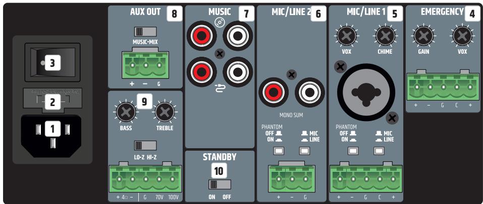
Connections, operating and display elements of the two units IMA 120 and IMA 240 are identical
1 POWER SOCKET
IEC socket for power supply to the unit (mains cable included).
2 FUSE
Fuse holder for 250 V fuses (5 x 20 mm). IMPORTANT NOTE: Replace the fuse only with a fuse of the same type (see printed instructions on the housing). Should the fuse blow repeatedly, please contact an authorised service centre.
3 ON/OFF
Rocker switch for switching the device on and off.
4 EMERGENCY
The 5-pole terminal block connection is used to install an acoustic emergency call system. The poles +, - and G correspond to a balanced line input. The poles C and + are used to connect a separate mute switch (terminal block included). The Emergency contact closure (pins C and + ) allows muting of all other input channels, independently from the VOX setup from the VOX setting.
CLIP: The red CLIP LED indicates when the input is operated at the distortion limit. Reduce the signal level using the GAIN control or on the playback device so that the CLIP LED is no longer lit.
Vox: The Vox (Voice Operated Exchange) control offers the possibility to set a threshold for the emergency audio signal, thus activating an automatic mute circuit. When the level at the EMERGENCY input reaches the set threshold, all other microphone and line channels are muted. This ensures that the emergency signal can be heard clearly. In addition, the EMERG indicator at the front of the amplifier lights up in this case. As soon as the level of the emergency signal falls below the set threshold, the muted of the other channels is cancelled again and the EMERG display goes out. With the appropriate setting, the EMERGENCY channel always has the highest priority. The emergency signal is transferred internally directly to the LINE OUT audio output. If the Vox control is set to minimum (turned all the way to the left), the automatic muted via Vox circuitry is deactivated and the EMERGENCY channel can be used as an additional line channel.
GAIN: Control for adjusting the pre-amplification of the incoming audio signal. Adjust the gain control so that the channel's clip LED only lights up briefly during signal level peaks. Avoid permanent glow of the clip LED by reducing the pre-amplification. It may also be necessary to reduce the signal level on the source device. The level of the emergency signal is not influenced by the current setting of the main volume control (Master Volume), but is adjusted via the GAIN control.
5 MIC/LINE1
Microphone/line channel with switchable gong function (signal tone). The connection can be made via the XLR/jack combo socket as well as via terminal block. In this case, the poles + , - and G on the terminal block connection are intended for the balanced input signal.
The poles C and + are used to connect a separate mute switch (terminal block included). The contact closure offers the possibility to mute the MUSIC channel via an external switch/button. In addition, the internal gong/signal tone function can be controlled in this way if the circuit is activated (see point 6 MIC/LINE 2, CHIME).
MIC/LINE: If a line signal is present at the XLR/jack combo socket or at the terminal block, switch MIC/ LINE channel 1 to LINE mode via the associated MIC/LINE switch (switch pressed). If a microphone is connected, activate MIC mode via the MIC/LINE switch (switch not pressed).
PHANTOM ON/OFF: When using a condenser microphone, it is necessary to activate the 24 V phantom power supply (PHANTOM ON/OFF switch pressed: ON). Always make sure that the microphone is connected and the channel volume is set to minimum before switching on the phantom power. Before disconnecting the microphone from the unit again, deactivate the phantom power and turn the channel volume to minimum.
GAIN: Control for adjusting the pre-amplification of the incoming audio signal. Adjust the gain control so that the channel's clip LED only lights up briefly during signal level peaks. Avoid permanent glow of the clip LED by reducing the pre-amplification. It may also be necessary to reduce the signal level on the source device.
CLIP: The red CLIP LED indicates when the input is operated at the distortion limit. Reduce the signal level on the GAIN control or on the playback device so that the CLIP LED is no longer lit.
Vox: The Vox control allows you to set an audio threshold for an automatic mute circuit for MIC/LINE input 1, so that the MIC/LINE 2 and MUSIC channels are muted as soon as the input signal reaches the predefined level. The PRIO LED on the front lights up when the NO contact or Vox circuit is active. As soon as the input level of the emergency signal falls below the set threshold, the muting of the channels is cancelled again and the PRIO LED goes out. If configured accordingly, MIC/LINE 1 has priority over MIC/LINE 2 and MUSIC. Adjust the channel volume using control 1 on the front of the unit.
MIC/LINE2
Microphone/line channel with switchable gong function (signal tone). The connection can be made via the RCA sockets (line level, a stereo signal is summed mono) or via terminal block. In this case, the poles + , - and G on the terminal block connection are intended for the balanced input signal.
MIC/LINE: If a line signal is present at the terminal block connection, switch MIC/LINE channel 2 to LINE mode via the associated MIC/LINE switch (switch pressed). If a microphone is connected to the terminal strip connector, activate MIC mode via the MIC/LINE switch (switch not pressed).
PHANTOM ON/OFF: When using a condenser microphone, it is necessary to activate the 24 V phantom power supply (PHANTOM ON/OFF switch pressed: ON). Always make sure that the microphone is connected and the channel volume is set to minimum before switching on the phantom power. Before disconnecting the microphone from the unit again, deactivate the phantom power and turn the channel volume to minimum.
GAIN: Control for adjusting the pre-amplification of the incoming audio signal. Adjust the gain control so that the channel's clip LED only lights up briefly during signal level peaks. Avoid permanent glow of the clip LED by reducing the pre-amplification. It may also be necessary to reduce the signal level on the source device.
CLIP: The red CLIP LED indicates when the input is operated at the distortion limit. Reduce the signal level on the GAIN control or on the playback device so that the CLIP LED is no longer lit.
CHIME: The volume for the gong/signal tone is controlled by the CHIME control on the back of the amplifier. When the control is turned all the way to the left, the gong/signal tone circuit is deactivated. If the internal gong/signal tone function is active, the MIC/LINE 1, MIC/LINE 2 and MUSIC channels are muted for the duration of the signal tone. The signal tone is triggered by means of a push-button with normally open function, which is connected to the contacts C and + of channel MIC/LINE 1.
Adjust the channel volume using control 2 on the front of the unit.
7 MUSIC
Line channel for integrating playback devices such as CD or MP3 players (a stereo signal is summed mono). The MUSIC channel is additionally equipped with a Bluetooth module. RCA sockets for connecting two stereo line input signal sources are available at the rear (CD symbol or cable symbol). The desired signal source is selected via a touch-sensitive button on the front of the amplifier. Adjust the channel volume using the MUSIC control on the front of the unit.
AUX OUT
The line output AUX OUT with terminal block connection is used for sending a signal, for example, to an external amplifier, an active subwoofer or a system for telephone music on hold (terminal block included). The MUSIC-MIX button can be used to transfer only the signal of the music channel (MUSIC position) or the sum of all channels (MIX position) to the output.
Please note: In the factory setting, the EMERGENCY signal (emergency signal) is routed to the AUX OUT line output via an internal jumper. If this setting is to be changed, the unit must be opened and the corresponding jumper removed. Please refer to "JUMPER FOR EMERGENCY SIGNAL TO AUX OUT" in this instruction manual.
9 SPEAKER OUTPUT
The loudspeaker output with terminal block connection (terminal block included in the packaging) enables to use both low-impedance loudspeakers with an impedance of at least 4 ohms (LO-Z/HI-Z key in LO-Z position) and 70/100 V loudspeakers (LO-Z/HI-Z key in HI-Z position). Please note the correct assignment of the terminal block poles (see illustration below). The tonal adjustment of the speaker signal is done via the controls BASS (bass) and TREBLE (treble). The total output power of the connected speakers should roughly correspond to the amplifier power.
10 STANDBY ON/OFF
If the standby function is activated (STANDBY in position ON), the amplifier will automatically go into standby mode if no audio signal is detected for 20 minutes. This reduces power consumption in a sensible way. As soon as an audio signal is present, the amplifier is automatically booted up from standby mode and is fully operational again within approx. 3 seconds (during booting, the standby LED on the front panel flashes white). If the STANDBY LED lights up white continuously, the unit is ready for operation. In standby mode, the LED lights up red. In addition, the IMA 120 or IMA 240 can also be put into standby mode manually by pressing the standby button on the front panel. In this case, the auto-standby mode is deactivated and the unit does not start up again automatically.
Please note: When the Auto Standby switch is active, the Bluetooth connection status is also analysed. If a Bluetooth connection with a playback device (e.g. smartphone or tablet) is detected and Bluetooth is selected as the signal source, the unit is not automatically set to standby mode.
Connections, operating and display elements of the two units IMA 120 and IMA 240 are identical
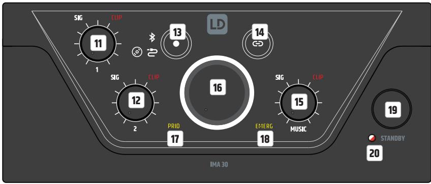
CHANNEL1
Volume control for channel 1 with white SIG (signal) and red CLIP LED. As soon as an audio signal is present at channel 1 and the volume control 1 is set to the desired volume, the white signal LED lights up. If the red CLIP LED lights up, distortion of the signal may occur.
In this case, reduce the output level of the source device or the channel volume (control 1) on the amplifier. If distortion still occurs, please check the corresponding input stage on the back of the amplifier (CLIP LED / GAIN).
12 CHANNEL 2
Volume control for channel 2 with white SIG (signal) and red CLIP LED. As soon as an audio signal is present at channel 2 and the volume control 2 is set to the desired volume, the white signal LED lights up. If the red CLIP LED lights up, distortion of the signal may occur. In this case, reduce the output level of the source device or the channel volume (control 2) on the amplifier. If distortion still occurs, please check the corresponding input stage on the back of the amplifier (CLIP-LED / GAIN).
13
Touch-sensitive button for selecting the audio source for the MUSIC channel (Bluetooth module, input with CD symbol, input with cable symbol). To switch the signal source, touch the key for at least half a second. The individual signal sources are activated in a clockwise direction.
14
Touch-sensitive button for activating the Bluetooth connection (pairing). The connection of a Bluetooth accessory device (e.g. smartphone, tablet, etc.) with the Bluetooth module of the amplifier is done by selecting the Bluetooth signal source (see item 13). If no external player is connected to the Bluetooth module, this is indicated by the Bluetooth symbol flashing slowly. To connect to an external player, press the Bluetooth pairing button for approx. 2 seconds until the Bluetooth symbol flashes faster. Now the Bluetooth ID is visible to other Bluetooth devices. Activate the Bluetooth function of the external player and search for nearby Bluetooth devices via the Bluetooth menu. When the LD IMA 120 or IMA 240 appears under „Available devices“, you only need to select it and the connection will be established automatically. When pairing is complete, the Bluetooth icon on the front of the device will light up and remain on. The Bluetooth ID is no longer visible to other devices to prevent unauthorized pairing with the Bluetooth module. Now playback can be started via the external player. If you want to disconnect the pairing with a connected Bluetooth device again so that the Bluetooth module can be connected to another device, press the Bluetooth button again for approx. 2 seconds. You can then integrate the desired playback device into the setup by selecting the LD IMA 120 or IMA 240 in the Bluetooth menu (“Connected devices”) of the playback device.
15 MUSIC
Volume control for the MUSIC channel with white SIG (signal) and red CLIP LED. As soon as an audio signal is present at the MUSIC channel and the corresponding volume control is set to the desired volume, the white signal LED lights up. If the red CLIP LED lights up, distortion of the signal may occur. In this case, reduce the output level of the source device or the channel volume (MUSIC control) on the amplifier.
16 MASTER VOLUME CONTROLLER
The main volume control is used to control the sum signal of all channels except the EMERGENCY channel. The EMERGENCY channel bypasses the main volume control and the signal is passed directly to the power amp and speaker output. The main volume control is equipped with a ring-shaped, three-colour LED indicator. This LED ring remains dark when there is no signal or only a very weak signal at the output and starts to light up as soon as a sufficient signal level is detected. If the internal limiter intervenes, the ring lights up yellow. Red light indicates that due to a technical problem (e.g. short circuit in the loudspeaker cable) the protection circuit of the amplifier has been activated. In this case, the output is muted. Switch the device off. If the technical problem cannot be solved, please contact an authorised service centre.
17 PRIO
Display field for activated priority mode of the MIC/LINE channels (priority levels 2, 3 and 4). The priority function of the MIC/LINE channels is activated in the following three situations, and the PRIO indicator on the front panel lights up yellow:
- The VOX circuit is active (input signal level MIC/LINE 1 exceeds the set VOX threshold).
- The contact between the poles C and + of the terminal block connection for channel MIC/LINE 1 is closed via a mute switch/button.
- The gong/signal tone is played.
For more information on the channel priorities and the EMERG and PRIO indicator panels on the front panel of the amplifier, see the PRIORITY LEVELS table in this manual.
18 EMERG
Display field for the priority feature of the Emergency channel. The EMERG indicator lights up yellow when priority level 1 is activated by VOX emergency circuit or via a connected mute switch/button (normally open contact). At the same time, all other input channels are muted. As soon as the contact opens again or the emergency signal level falls below the defined VOX threshold, all channels are unmuted and the EMERG indicator goes out.
19 STANDBY BUTTON
A short press on the standby button puts the amplifier into standby mode, and the speaker outputs are muted. If the standby button is briefly pressed a second time, the amplifier is ready for operation again. When standby mode is activated by pressing the standby button, reactivation of the amplifier via the automatic standby function is not available, even if an audio signal is detected.
20 STANDBY LED
Two-colour LED to indicate the current operating status. During the start-up process, the standby LED flashes white. The LED lights up permanently white when the start-up process is completed and the unit is ready for operation. When the unit is put into standby mode, the LED flashes red until the process is completed. In standby mode, the LED lights up permanently red.
PRIORITY LEVELS
| PRIORITY-LEVELS | TRIGGER SIGNAL SOURCE | MUTED SIGNAL SOURCES | ACTIVE SIGNAL SOURCES | FRONT DISPLAY |
| 1 | Emergency VOX circuit & normally open contact | MIC/LINE 1 | EMERGENCY SIGNAL | EMERG |
| MIC/LINE 2 | ||||
| MUSIC | ||||
| 2 | MIC/LINE 1 VOX | MIC/LINE 2 | EMERGENCY SIGNAL | PRIO |
| MUSIC | MIC/LINE 1 | |||
| 3 | MIC/LINE 1, normally open contact during gong/signal tone Playback | MIC/LINE 1 | EMERGENCY SIGNAL | PRIO |
| MIC/LINE 2 | ||||
| MUSIC | ||||
| 4 | MIC/LINE 1, normally open contact after gong/signal tone Playback | MUSIC | EMERGENCY SIGNAL | PRIO |
| MIC/LINE 1 | ||||
| MIC/LINE 2 | ||||
| 5 | - | - | EMERGENCY SIGNAL | - |
| MIC/LINE 1 | ||||
| MIC/LINE 2 | ||||
| MUSIC |
CONNECTION EXAMPLES
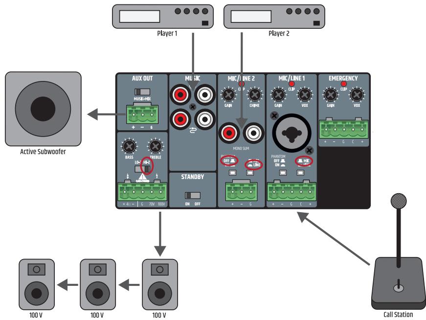
The connection for a mute switch/button in MIC/LINE channel 1 can be used for two devices at the same time (muting a music signal or activating the gong/signal tone). In this case, the mute contacts of both units must be connected to the poles C and + of the terminal block connection for MIC/LINE 1.
When wiring terminal blocks, please observe the correct assignment of the poles/terminals (see illustration under the connection examples for terminal blocks). The manufacturer accepts no liability for damage caused by faulty wiring! For more information on the correct wiring of terminal block connections ("Terminal Blocks"), see the TERMINAL BLOCK CONNECTIONS section of this manual.
TERMINAL BLOCK CONNECTIONS
LINE OUTPUT AUX OUT
SPEAKER CONNECTIONS (LOW IMPEDANCE, 100 V AND 70 V LOUDSPEAKERS)
INPUTS CHANNELS 1 AND 2
INPUTS EMERGENCY CHANNEL
In the factory setting, the EMERGENCY signal is routed to the AUX OUT line output via an internal jumper. If this setting is to be changed, the unit must be opened and the corresponding jumper removed.

IMPORTANT:
Opening the unit to change the configuration using jumpers requires technical expertise and may only be carried out by appropriately trained persons! If you are not qualified to do so, never carry out such interventions yourself, but contact trained service technicians.
Take care when opening the amplifier and changing the configuration. This way you avoid damage to the appliance and personal injury. Follow the individual steps in these instructions carefully. The manufacturer accepts no liability for damage to property or personal injury caused by improper handling.
- Disconnect the amplifier completely from the mains (pull out the mains plug)!
- Disconnect all cables from the amplifier.
- Wait at least one minute before opening the housing to make sure that there is no dangerous voltage inside!
- Loosen and remove the two screws on the sides of the amplifier A, the four correspondingly labelled screws on the back B and one screw on the top of the amplifier C (nine screws in total) using a suitable tool. Note the positions of the three different types of screws.
- Pull the housing cover backwards off the housing.
- Pull the jumper shown in figure 2D off the contacts (inside rear of unit).
- Slide the housing cover back onto the housing from behind and screw it tight with the screws you loosened earlier.
Now the emergency signal of the EMERGENCY channel is no longer routed to the AUX OUT output.
RACK MOUNTING
(Rack mounting kit LDIMARK optionally available)
The optionally available LDIMARK rack-mount kit includes housing adapters and connectors for fixed installation of IMA 120 or IMA 240 mixer amplifiers (single or two side-by-side) in a 19" rack.
The mounting kit includes the following components:
2 rack adapters with short sides A , 1 rack adapter with long sides B , 2 small plates for the back C ,
2 rectangular plates for the bottom D, 4 M4 pan head screws for the rack brackets, 8 M3 countersunk screws for plate D.
The installation of a single amplifier requires a rack adapter with short side A and the rack adapter with long side B. Screw the adapter with the short side to the left or right side of the amplifier and the adapter with the long side to the opposite side. Use the M4 flat-head screws for this purpose.
If you want to mount two amplifiers side by side in a 19" rack, you will need the two small plates to connect the amplifiers at the back C, the two rectangular plates to connect them at the bottom D and the two rack adapters with short sides A. Loosen the corresponding screws on the back and use these screws to screw down the panels C. Screw the connectors D to the designated positions on the amplifiers with the enclosed M3 countersunk screws, as shown below. Now screw the rack adapters with the short sides A to the sides of the units using the M4 pan head screws.
UNDER-TABLE MOUNTING
(Rack adapter optionally available with rack mounting kit LDIMARK).
For under-table mounting, two M4 threaded holes are provided at the top corners of the amplifier housing. Screw the two rack adapters A with the short sides to the two housing sides using the enclosed M4 flat-head screws (see illustration). Now the amplifier can be fixed in the desired position under a table.

CARE, MAINTENANCE AND REPAIR
In order to ensure the long-term, proper functioning of the device, it must be regularly cleaned and, if necessary, maintained. The maintenance requirement depends on the intensity of use and the environment in which it is used.
We generally recommend a visual inspection before each operation. Furthermore, we recommend carrying out all the applicable maintenance measures specified below once every 500 operating hours or, in the case of a lower intensity of use, at the latest after one year. Warranty claims may be limited in the event of defects resulting from inadequate maintenance.
CARE (CARRIED OUT BY USER)

Before carrying out any maintenance work, the power supply and, if possible, all device connections must be unplugged.

NOTE! Improper care can lead to impairment of the unit up to and including destruction.
- Housing surfaces must be cleaned with a clean, damp cloth.
Make sure that no moisture can penetrate the device. - Air inlets and outlets must be regularly cleaned of dust and dirt. If compressed air is used, make sure that damage to the device is prevented (e.g. fans must be blocked in this case).
- Lines and plug contacts must be cleaned regularly and dust and dirt must be removed.
- In general, no cleaning agents or abrasive agents may be used, otherwise the surface finish may be damaged. Especially solvents, such as alcohol, can impair the function of housing seals.
- Devices must generally be stored dry and protected from dust and dirt.
MAINTENANCE AND REPAIR (BY QUALIFIED PERSONNEL ONLY)

DANGER! There are live components in the unit. Even after disconnecting the mains connection, there may still be residual voltage in the device, for example, due to charged capacitors.

PLEASE NOTE! There are no user-serviceable assemblies in the device.

NOTE! Maintenance and repair work may only be carried out by specialist personnel authorised by the manufacturer. If in doubt, consult the manufacturer.

PLEASE NOTE! Improperly performed maintenance work may affect warranty claims.
TECHNICAL DATA
| Item number | LDIMA120 | LDIMA240 |
| Product type | Installation mixing amplifier | |
| Emergency input | 1 balanced line input | |
| Mic/Line inputs | 2 | |
| Music sources | 2 unbalanced stereo line inputs + 1 Bluetooth interface v4.0 | |
| Line outputs | 1 | |
| Powered outputs | 1 with output mode selector (LO-Z/HI-Z) | |
| Cooling system | Convection cooling | |
| Priority levels | 4 | |
Emergency Input
| Nominal input sensitivity | -15 dBu (sine 1 kHz, Gain max) | |
| Nominal input clipping | 20 dBu (sine 1 kHz, Gain 0dB) | |
| THD+N | < 0.04% (SPK OUT, -20 dBu, 20-20 kHz, Gain max, 20 kHz BW) | < 0.03% (SPK OUT, -20 dBu, 20-20 kHz, Gain max, 20 kHz BW) |
| < 0.01% (AUX OUT, -6 dBu, 20-20 kHz, Gain max, 20 kHz BW) | < 0.01% (AUX OUT, -6 dBu, 20-20 kHz, Gain max, 20 kHz BW) | |
| Frequency response | 12 Hz - 20 kHz (L0-Z SPK OUT, -3 dB) | |
| 10 Hz - 20 kHz (AUX OUT, -3 dB) | ||
| Input Impedance | 10 kohms (balanced) | |
| SNR | >88 dB (SPK OUT, -6 dBu, CH Gain max (0 dB), Master Gain min (-inf), 20 kHz BW, A-weighted) | |
| >87 dB (AUX OUT, -6 dBu, CH Gain max (0 dB), 20 kHz BW, A-weighted) | ||
| SNR (Best conditions) | >92 dB (SPK OUT, +18 dBu, Gain 0 dB, Master Gain -inf, 22 kHz BW, A-weighted) | |
| >110 dB (AUX OUT, +18 dBu, Gain 0 dB, 22 kHz BW, A-weighted) | ||
| CMRR | >48 dB (SPK OUT, AUX OUT, -6 dBu 1 kHz) | |
| Gain | -15 to 42 dB | |
| VOX Threshold | 0%: Off, 25%: -6 dBu, 50%: -27 dBu, 100%: -35 dBu | |
| Priority Contact closure | +5VDC Normally Open for dry contact | |
| Connector | 1x 5.08 mm Terminal Block 5-pin | |
| Standby wake up threshold | -40 dBu | |
| Item number | LDIMA120 | LDIMA240 |
| Mic/Line inputs 1-2 | ||
| Nominal input sensitivity | Mic: -36 dBu (sine 1 kHz, Gain max) (without PA Gain)Line: -20 dBu (sine 1 kHz, Gain max) | |
| Nominal input clipping | Mic: -1 dBu (sine 1 kHz)Line: +19 dBu (sine 1 kHz) | |
| THD+N | Mic: < 0.2% (SPK OUT, -42 dBu, 20-20 kHz, Gain max, 20 kHz BW)< 0.02% (AUX OUT, -38 dBu, 20-20 kHz, Gain max, 20 kHz BW)Line: < 0.1% (SPK OUT, +4 dBu, 20-20 kHz, CH Gain max, Master Gain max (0 dB),20 kHz BW)< 0.02% (AUX OUT, +4 dBu, 20-20 kHz, CH Gain max, 20 kHz BW) | |
| Frequency response | Mic: 85 Hz - 20 kHz (SPK OUT, -3 dB)85 Hz - 20 kHz (AUX OUT, -3 dB)Line: 19 Hz - 20 kHz (SPK OUT, -3 dB)20 Hz - 20 kHz (AUX OUT, -3 dB) | |
| Input Impedance | Mic: 1,8 kohms (balanced)Line: 10 kohms (balanced) | |
| SNR | Mic: >81 dB (SPK OUT, -21 dBu, Gain max (0 dB), Master Gain max (0 dB),22 kHz BW, A-weighted)>82 dB (AUX OUT, -38 dBu, Gain max (0 dB), 22 kHz BW, A-weighted)Line: >90 dB (SPK OUT, +4 dBu, CH Gain max (0 dB), Master Gain max (0 dB),20 kHz BW, A-weighted)>89 dB (AUX OUT, +4 dBu, CH Gain max (0 dB), 20 kHz BW, A-weighted) | |
| SNR (Best conditions) | Mic: >90 dB (SPK OUT, -3 dBu, CH Gain center, Master Gain MAX,20 kHz BW, A-weighted)>102 dB (AUX OUT, -18 dBu, Gain max (0 dB), 20 kHz BW, A-weighted)Line: >90 dB (SPK OUT, +18 dBu, CH Gain max (0 dB), Master Gain (-14 dB),20 kHz BW, A-weighted)>103 dB (AUX OUT, +18 dBu, CH Gain max (0 dB), 20 kHz BW, A-weighted) | |
| CMRR | Mic: >40 dB (SPK OUT, AUX OUT, 1 kHz)Line: >45 dB (SPK OUT, AUX OUT, 1 kHz) | |
| Gain | Mic: 12 to 70 dB (SPK OUT) / 38 dB (AUX OUT)Line: -37 to 48 dB (SPK OUT) / 18 dB (AUX OUT) | |
| Phantom Power | +24 V, 10 mA switchable | |
| VOX Threshold | Mic: 0%: Off, 25%: -40 dBu, 50%: -52 dBu, 100%: -66 dBuLine: 0%: Off, 25%: -6 dBu, 50%: -27 dBu, 100%: -35 dBu | |
| Priority Contact closure | +5VDC Normally Open for dry contact | |
| Connector | Mic/Line1: 5-pin Terminal Block, pitch 5.08 mm + 1 XLR/6.3mm Jack combo connector Mic/Line2: 3-pin Terminal Block, pitch 5.08 mm + 1 dual RCA Mono Summed | |
| Standby wake up threshold | Mic: -66 dBu Line: -35 dBu (Line), -40 dBu (Mono Sum) | |
| Chime | ||
| Play time | 2s | |
| Resolution | 12 Bit | |
| Music inputs – CD/AUX | ||
| Nominal input sensitivity | -6.2 dBV (sine 1 kHz, Gain max) | |
| Nominal input clipping | 8 dBV (sine 1kHz) | |
| Connector | 2 x dual RCA Mono Summed | |
| THD+N | < 0.05% (SPK OUT, -6 dBu, 20-20 kHz, CH Gain max, Master Gain max (0 dB), 20 kHz BW) < 0.01% (AUX OUT, -6 dBu, 20-20 kHz, CH Gain max, 20 kHz BW) | |
| Frequency response | 18 Hz – 20 kHz (SPK OUT, -3 dB) 20 Hz – 20 kHz (AUX OUT, -3 dB) | |
| Input Impedance | 20 kohms (unbalanced) | |
| SNR | >86 dB (SPK OUT, -4 dBu, CH Gain max (0 dB), Master Gain max (0 dB), 20 kHz BW, A-weighted) >90 dB (AUX OUT, -6 dBu, CH Gain max (0 dB), 20 kHz BW, A-weighted) | |
| SNR (Best conditions) | >90 dB (SPK OUT, +10 dBu, CH Gain max (0 dB), Master Gain (-16 dB), 20 kHz BW, A-weighted) >104 dB (AUX OUT, +10 dBu, Gain max (0 dB), 20 kHz BW, A-weighted) | |
| Gain | -Inf to 5 dB (AUX), 30 dB (SPK) | |
| Standby wake up threshold | -45 dBu | |
| Music input – BT | ||
| THD+N | < 0.2% (SPK OUT, -10 dBFs, 20-20 kHz, Gain max, 20 kHz BW) < 0.2% (AUX OUT, -10 dBFs, 20-20 kHz, Gain max, 20 kHz BW) | |
| Frequency response | 25 Hz – 20 kHz (SPK OUT, -3 dB) 25 Hz – 20 kHz (AUX OUT, -3 dB) | |
| SNR | >80 dB (SPK OUT, -10 dBFs, Gain max (0 dB), 20 kHz BW, A-weighted) >80 dB (AUX OUT, -10 dBFs, Gain max (0 dB), 20 kHz BW, A-weighted) | |
| SNR (Best conditions) | >86 dB (SPK OUT, 0 dBFs, CH Gain max (0 dB), Master Gain (-10 dB), 20 kHz BW, A-weighted) >93 dB (AUX OUT, 0 dBFs, Gain max (0 dB), 20 kHz BW, A-weighted) | |
| Amplifier Output | ||
| Type | Class D | |
| Amplifier Outputs | L0-Z: 4 ohm minimum load, HI-Z 70V or 100V outputs | |
| Connector | 5-pin Terminal block (pitch 5.08 mm) | |
| RMS output power | 125 W (continuous sine wave 1 kHz, 4 ohm load) | 240 W (continuous sine wave 1 kHz, 4 ohm load) |
| Peak output power | 135 W (100 msec sine 1 kHz Burst @ 4 ohm load) Peak Limiter | 250 W (100 msec sine 1 kHz Burst @ 4 ohm load) Peak Limiter |
| Frequency response | 15 Hz - 20 kHz (L0-Z, -3 dB)60 Hz - 20 kHz (HI-Z, -3 dB) | |
| Tone Control | BASS: ++10 dB (100 Hz), TREBLE: ++10 dB (10 kHz) | |
| Protection | Audio Limiter (10 dB range), Over/Undervoltage, Overtemperature, Short-Circuit, Offset-Detection | |
| Aux Output | ||
| Connector | 3-pin Terminal block (pitch 5.08 mm) | |
| Frequency response | 20 Hz - 20 kHz (-3 dB) | |
| Maximum output level | 22 dBu | |
| Power Supply | ||
| Type | SMPS | |
| Voltage Range | 100 VAC - 240 VAC (+-10%), 50-60 Hz | |
| Mains fuse | T4AL 250V | T6.3AL 250V |
| Connector | IEC Jack | |
| Safety Class | Class 1 | |
| Max power consumption | 165 W (sine 1 kHz with 4 ohm load) | 300 W (sine 1 kHz with 4 ohm load) |
| Idle power consumption | 13 W (no signal input) | 15 W (no signal input) |
| Standby power consumption | < 1 W | |
| Operating Temperature | 0°C - 40°C; < 85% humidity, non condensing | |
| General | ||
| Time to standby | 20 min | |
| Material | Steel chassis, Plastic Front panel | |
| Dimensions (W x H x D) | 210 x 95 x 266.76 mm (height with rubber feet) | |
| Weight | 3.01 kg | 3.5 kg |
| Optional Accessories | Rack mounting kit | |
DISPOSAL

Packaging:
- Packaging can be fed into the reusable material cycle using the usual disposal methods.
- Please separate the packaging in accordance with the disposal laws and recycling regulations in your country.

Device:
- This device is subject to the European Directive on Waste Electrical and Electronic Equipment, as amended. WEEE Directive Waste Electrical and Electronic Equipment. Old appliances and batteries do not belong in household waste. The old appliance or batteries must be disposed of via an authorised waste disposal company or a municipal waste disposal facility. Please observe the applicable regulations in your country!
- Observe all disposal laws applicable in your country.
- As a private customer, you can obtain information on environmentally-friendly disposal options from the seller of the product or the appropriate regional authorities.

Batteries:
- Batteries should not be disposed of in household waste. Batteries must be disposed of via an approved disposal company or a municipal disposal facility.
- Observe all disposal laws and regulations applicable in your country.
- As a private customer, you can obtain information on environmentally-friendly disposal options from the seller of the product or the appropriate regional authorities.
- Devices with batteries that cannot be removed by the user must be taken to a collection point for electrical devices.
MANUFACTURER'S DECLARATIONS
MANUFACTURER'S WARRANTY & LIMITATION OF LIABILITY
Adam Hall GmbH, Adam-Hall-Str. 1, 61267 Neu Anspach, Germany
E-mail Info@adamhall.com / +49 (0)6081 / 9419-0.
Our current warranty conditions and limitation of liability can be found at:
https://cdn-shop.adamhall.com/media/pdf/MANUFACTURERS-DECLARATIONS_LD_SYSTEMS.pdf.
Contact your distribution partner for service.
UKCA-CONFORMITY
Hereby, Adam Hall Ltd. declares that this product meets the following guidelines (where applicable) Electrical Equipment (Safety) Regulations 2016
Electromagnetic Compatibility Regulations 2016 (SI 2016/1091)
The Restriction of the Use of Certain Hazardous Substances in Electrical and Electronic Equipment Regulation 2012 (SI 2012/3032)
Radio Equipment Regulations 2017(SI 2016/2015)
UKCA-DECLARATION OF CONFORMITY
Products that are subject to Electrical Equipment(Safety)Regulation 2016, EMC Regulation 2016 or RoHS Regulation can be requested at info@adamhall.com. Products that are subject to the Radio Equipments Regulations 2017 (SI2017/1206) can be downloaded from
www.adamhall.com/compliance/
FCC STATEMENT
- This device complies with Part 15 of the FCC Rules. Operation is subject to the following two conditions:
(1) This device may not cause harmful interference, and
(2) This device must accept any interference received, including interference that may cause undesired operation.
- Changes or modifications not expressly approved by the party responsible for compliance could void the user's authority to operate the equipment.
RADIATION EXPOSURE STATEMENT
This equipment complies with FCC radiation exposure limits set forth for an uncontrolled environment. This equipment should be installed and operated with minimum distance 20cm between the radiator & your body.
NOTE: This equipment has been tested and found to comply with the limits for a Class B digital device, pursuant to Part 15 of the FCC Rules. These limits are designed to provide reasonable protection against harmful interference in a residential installation. This equipment generates, uses and can radiate radio frequency energy and, if not installed and used in accordance with the instructions, may cause harmful interference to radio communications. However, there is no guarantee that interference will not occur in a particular installation. If this equipment does cause harmful interference to radio or television reception, which can be determined by turning the equipment off and on, the user is encouraged to try to correct the interference by one or more of the following measures:
Reorient or relocate the receiving antenna.
- Increase the separation between the equipment and receiver.
- Connect the equipment into an outlet on a circuit different from that to which the receiver is connected.
- Consult the dealer or an experienced radio/TV technician for help.
Misprints and errors as well as technical or other changes are reserved!
DEUTsCH
https://cdn-shop.adamhall.com/media/pdf/MANUFACTURERS-DECLARATIONS_LD_SYSTEMS.pdf.
https://cdn-shop.adamhall.com/media/pdf/MANUFACTURERS-DECLARATIONS_LD_SYSTEMS.pdf.
Directive CEM (2014/30/UE)
ROHS (2011/65/UE)
ROUGE (2014/53/EU)
DECLARATION DE CONFORMITE CE
www.Id-systems.com/LDIMA120-downloads lub www.Id-systems.com/LDIMA240-downloads
https://cdn-shop.adamhall.com/media/pdf/MANUFACTURERS-DEclarations_LD_SYSTEMS.pdf.
www.adamhall.com/compliance/.
DEKLARACJA ZGODNOSCI UE
www.Id-systems.com/LDIMA120-downloads oppure


- DEUTSCH
- ENGLISH
- YOU HAVE MADE THE RIGHT CHOICE!
- INFORMATION ON THIS USER MANUAL
- PROPER USE
- DEFINITIONS AND SYMBOL EXPLANATIONS
- SAFETY INSTRUCTIONS
- DANGER:
- WARNING:
- ATTENTION:
- CAUTION:
- PLEASE NOTE:
- CAUTION: HIGH VOLUME AUDIO PRODUCTS!
- SIGNAL TRANSMISSION BY RADIO (e.g. W-DMX or audio radio systems, Bluetooth):
- INSTRUCTIONS FOR INDOOR INSTALLATION EQUIPMENT
- PACKAGING CONTENT
- LDIMA120
- LDIMA240
- INTRODUCTION
- FEATURES
- CONNECTIONS, OPERATING AND DISPLAY ELEMENTS
- POWER SOCKET
- FUSE
- ON/OFF
- EMERGENCY
- MIC/LINE1
- MIC/LINE2
- MUSIC
- AUX OUT
- SPEAKER OUTPUT
- STANDBY ON/OFF
- CHANNEL1
- CHANNEL 2
- 13
- 14
- MUSIC
- MASTER VOLUME CONTROLLER
- PRIO
- EMERG
- STANDBY BUTTON
- STANDBY LED
- CONNECTION EXAMPLES
- TERMINAL BLOCK CONNECTIONS
- IMPORTANT:
- RACK MOUNTING
- UNDER-TABLE MOUNTING
- CARE, MAINTENANCE AND REPAIR
- CARE (CARRIED OUT BY USER)
- Before carrying out any maintenance work, the power supply and, if possible, all device connections must be unplugged.
- MAINTENANCE AND REPAIR (BY QUALIFIED PERSONNEL ONLY)
- DISPOSAL
- Packaging:
- Device:
- Batteries:
- MANUFACTURER'S DECLARATIONS
- MANUFACTURER'S WARRANTY & LIMITATION OF LIABILITY
- UKCA-CONFORMITY
- UKCA-DECLARATION OF CONFORMITY
- FCC STATEMENT
- RADIATION EXPOSURE STATEMENT
- DECLARATION DE CONFORMITE CE
- DEKLARACJA ZGODNOSCI UE
Brand : LD Systems
Model : LDIMA120
Category : Amplifier