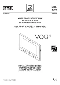
1760/32 - Video phone holder Urmet - Free user manual and instructions
Find the device manual for free 1760/32 Urmet in PDF.



| Product type | Video door phone |
| Brand | Urmet |
| Model | 1760/32 |
| Screen | 7 inch TFT LCD, capacitive touch |
| Screen resolution | 1024 x 600 pixels |
| Dimensions (W x H x D) | 212 x 138 x 24 mm |
| Power supply | 24 V~ (alternating current) |
| Standby consumption | < 200 mA |
| Full load consumption | < 400 mA |
| Operating temperature | -5°C to +45°C |
| Main functions | Gesture controls, call to smartphone/tablet, ringtone customization (5 options), audio message recording (POST-IT) up to 32, video message recording up to 32, phonebook up to 127 users, open door indication, screen cleaning function, MUTE, hands-free and Push to talk modes |
| Home button | Blue backlit |
| IR sensor | For gesture controls |
| Connections | Left terminal block (S+, S-, CP, COM, PANIC, IN1, IN2) and right terminal block (V+, V-, LINE IN, LINE OUT) |
| WiFi | 2.4 GHz (2412-2462 MHz), max power 20 dBm |
| RFID | Mifare 13.56 MHz, power 69.5 dBμV/m @ 3m |
| Hearing aid compatible | Integrated |
| Compliance | FCC Part 15 Class B, WEEE directive |
| Installation | Flush-mount in box Mod. 503, recommended height 90-130 cm (according to disability law) |
| Maximum power distance | 20 m with cable cross-section 1 mm² |
Frequently Asked Questions - 1760/32 Urmet
User questions about 1760/32 Urmet
0 question about this device. Answer the ones you know or ask your own.
Ask a new question about this device
Download the instructions for your Video phone holder in PDF format for free! Find your manual 1760/32 - Urmet and take your electronic device back in hand. On this page are published all the documents necessary for the use of your device. 1760/32 by Urmet.
USER MANUAL 1760/32 Urmet
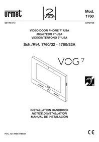
Sch./Ref. 1760/32 - 1760/32A
VOG

INSTALLATION HANDBOOK
NOTICE D'INSTALLATION
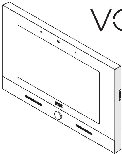
The video door phone VCG7 Ref.1760/32 is a device dedicated to the 2Voice system which can operate as:
Cutting-edge video door phone
- Terminal for displaying the video surveillance cameras
- Terminal for displaying the intrusion alarm control unit status
MIFARE access control
- Umet application manager (My 1067+, Umet Secure, CCTV)
Android application manager
The main features of the device used as video door phone terminal are:
colour 7” TFT-LCD screen (Wide Angle);
- possibility of activating video door phone functions via gesture commands on the IR detector or via vocal commands;
call forwarding function to smartphones and tablets;
- possibility of customising the ring tone with a choice of five different types;
- possibility of adjusting the ring tone volume;
- possibility of recording short audio messages (POST-IT for up to 32 messages);
- video door phone answering machine function (up to 32 messages);
- users book for intercom calls (up to 127 users);
- door open indication;
- "Screen cleaning" function;
- "MUTE" function;
- hands-free or push-to-talk mode:
- Hands-free: press the audio button once to start the conversation and once again to end it;
- Push-to-talk: press the audio button to speak to the door unit, release the button to listen.
The video door phone is supplied with local power supply unit.
2. DESCRIPTION OF COMPONENTS

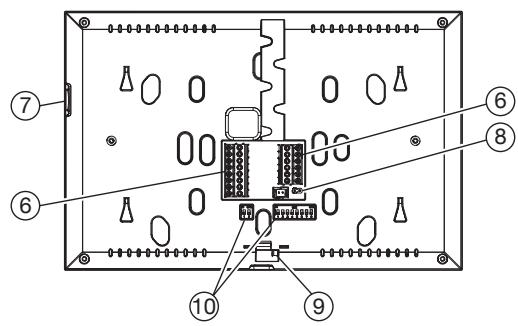
- Backlit blue Home button
- Speakers
- 7" touchscreen display
- IR detector for gesture commands
- Microphone
- Terminals for connection to the system
- Micro SD card
- Jumper for adjustment of Z line termination
- Video door phone locking latch
-
Configuration dip-switch (SW1 / SW2):
-
no.1 of SW1, not used;
- no. 2-8 of SW1, to define the apartment number in the column;
- no. 1-2 of SW2, to define the station number in the apartment.
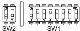


For DIP-switch settings for user code configuration, refer to the 2Voice system booklet.

Video door phone is provided with an embedded device for hard of hearing.
3. INSTALLATION
- Embed the flush-mounting box Mod. 503 in the wall or the flush-mounting box Ø 60 at the height shown in the following drawing.

The flush-mounting box Mod. 503 can be installed either horizontally or vertically.
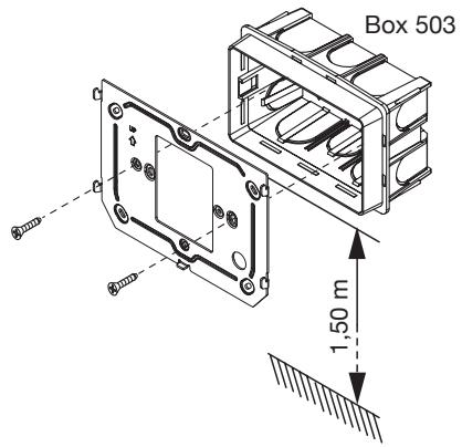
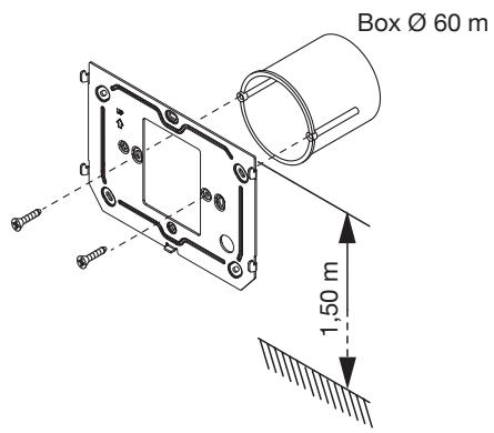
Fix the bracket to the mounting box as indicated.
- Program the dip-switches and connect the system wires to the terminal boards.
- Move the video door phone close to the bracket by centring the special fixings (1) and slide it down to reach its stop (2).
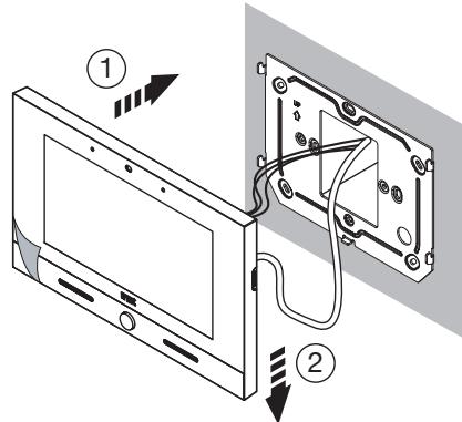
- Use a screwdriver to move the latch for locking the video door phone to the bracket from right to left.
- Remove the protective film from the display.
3.1. TERMINAL DESCRIPTION
Left terminal board
| ∅ | S+ | Positive for additional chime |
| ∅ | S- | Negative for additional chime |
| ∅ | CP | Floor call |
| ∅ | ||
| ∅ | COM | Common for panic alarm, alarm 1 input and alarm 2 input |
| ∅ | PANIC | Panic alarm |
| ∅ | IN1 | Alarm 1 input (intrusion alarm indication) |
| ∅ | IN2 | Alarm 2 input (technological alarm indication) |
Right terminal board
| ∅ | V+ | Terminals for local power supply |
| ∅ | V- | |
| ∅ | LINE IN | Power supply BUS input |
| ∅ | ||
| ∅ | LINE OUT | Power supply BUS output |
| ∅ |
3.2. LINE TERMINATION SETTINGS
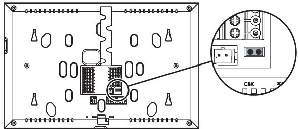
The Jumper (8) allows to adjust the line termination (Z) in case of in-out video door phone connection. The line termination must be inserted into the last video door phone.
| Termination inserted (default) |
| Termination not inserted |
4. CONTACT INSERTION FOR INTERCOM CALLS
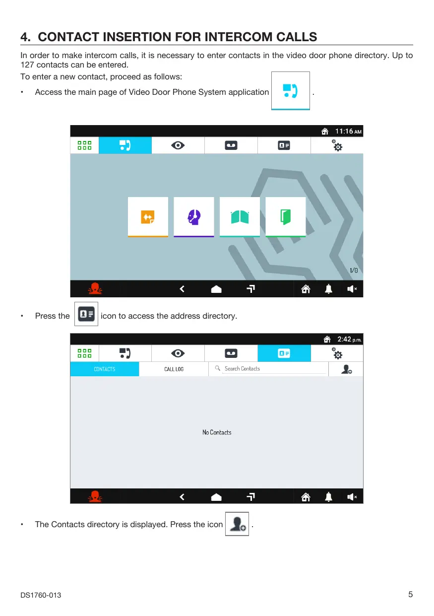
In order to make intercom calls, it is necessary to enter contacts in the video door phone directory. Up to 127 contacts can be entered.
To enter a new contact, proceed as follows:
- Access the main page of Video Door Phone System application

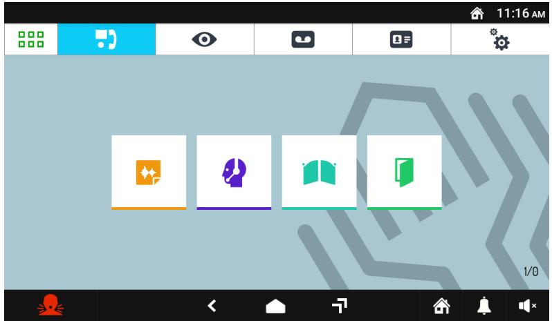
Press the

icon to access the address directory.
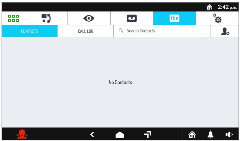
The Contacts directory is displayed. Press the icon
The request screen for entering a new contact opens.
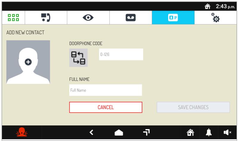
1. Contact type
Select the following icon to modify the contact type.
External contact: call to a video door phone in another apartment but within the same video door phone riser
Internal contact: call to a video door phone in the same apartment
For external contacts, permissible codes range from 0 to 126
For internal contacts, permissible codes range from 0 to 3
Use the virtual keypad and insert the video door phone ID code.
3. Contact name
Select the Full Name text box to insert the contact name.
Use the virtual keypad and insert the contact name.
Press the SAVE CHANGES key to save the contact in the directory.
Press the CANCEL key to cancel and return to the contact page.
5. RESET TO FACTORY SETTINGS
The reset to factory settings deletes all configurations made on the video door phone.
To reset to factory settings, proceed as follows:
- Turn on the screen, if off, by tapping it anywhere or by pressing the Home key.
Press the icon to access the Top Page.
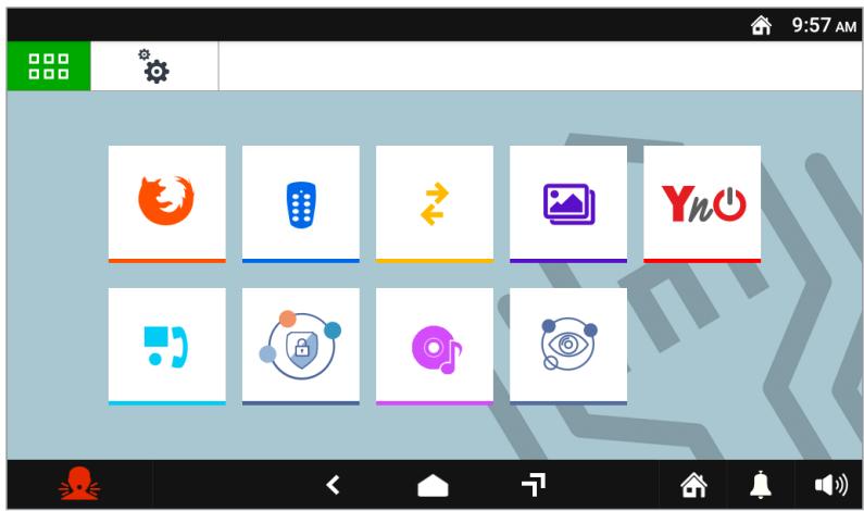
Press the icon to access the video door phone parameter configuration page.
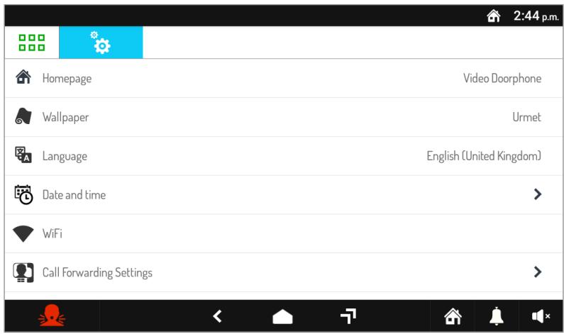
- Press on the Maintenance item to display the maintenance functions and parameters of the video door phone.
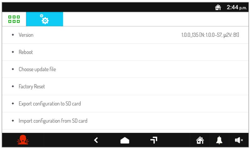
- In the menu, press Reset Factory Settings. A pop-up window is displayed on the screen to confirm the operation.
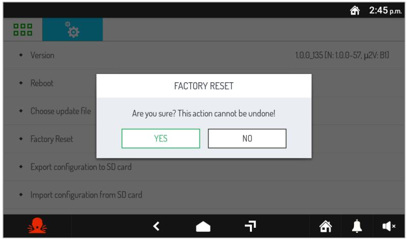
- Press the YES button to perform the operation and delete all the configurations in the video door phone and return it to the factory default configuration. Press the NO button to cancel the operation and close the pop-up window.
6. TECHNICAL SPECIFICATIONS
Power voltage (LINE IN): 36 ÷ 48 V=
Consumption (LINE IN): @ 48 V=
Standby: < 2 mA
Full rate: < 15 mA
Power voltage (V + ,V - ) . 24 V~
Consumption (V+; V-): @ 24 V~
Standby: < 200 mArms
Full rate: < 400 mArms
Maximum distance from local power supply: 20 m with cable sec. 1mm2
Frequency band
WiFi: 2.4 GHz (2412.0 ÷ 2462.0 MHz)
Mifare: 13.56 MHz
Output power (Max):
WiFi: 20 dBm
Mifare: 69.5 dBμV/m @ 3m
Terminals S+ and S- output: 25 mA @ 24 V=
Display: 7" TFT
Touchscreen: Capacitive
Display resolution: 1024 x 600 px
Brightness: 350 cd/m²
Viewing angle (H/V): 160° / 160°
Operating temperature: -5 ÷ 45°C
Dimensions (LxHxP): 212 x 138 x 24 mm

Wires with cross-section area of 0.5mm2 or larger must comply with IEC 60332-1-2; wires with cross section area smaller than 0.5mm2 must comply with IEC 60332-2-2.
7. KEY TO SYMBOLS
| Symbol | Description |
| --- | Direct input voltage |
| ~ | Alternating input voltage |
| ! | See the installation manual of the device |
8. SIMPLIFIED EU DECLARATION OF CONFORMITY
Hereby, URMET S.p.A. declares that the radio equipment type:
2VOICE VIDEO DOOR PHONE VOG' USA Ref. 1760/32 is in compliance with Directive 2014/53/EU.
The full text of the EU declaration of conformity is available at the following internet address:
www.urmet.com
1. DESCRIPTION GÉNÉRALE
Consummation Maximum (LINE IN): @ 48 V=
Au repos: < 2 mA
Luminosite: 350 cd/m2
Angle de vue (H/V): 160° / 160°
This device complies with Part 15 of the FCC rules. Operation is subject to the following two conditions:
1) This device may not cause harmful interference.
2) This device must accept all interference received, including interference that may cause undesired operation.
15.105 Information to the user statements:
This equipment has been tested and found to comply with the limits for a Class B digital device, pursuant to part 15 of the FCC Rules. These limits are designed to provide reasonable protection against harmful interference in a residential installation.
This equipment generates, uses and can radiate radio frequency energy and, if not installed and used in accordance with the instructions, may cause harmful interference to radio communications. However, there is no guarantee that interference will not occur in a particular installation.
If this equipment does cause harmful interference to radio or television reception, which can be determined by turning the equipment off and on, the user is encouraged to try to correct the interference by one or more of the following measures:
Reorient or relocate the receiving antenna.
- Increase the separation between the equipment and receiver.
- Connect the equipment into an outlet on a circuit different from that to which the receiver is connected.
- Consult the dealer or an experienced radio/TV technician for help.
RF exposure warning statement
To comply with FCC RF exposure compliance requirements, a separation distance of at least 20 cm must be maintained between the antenna of this device and all nearby persons.
Changes or modifications not expressly approved by the party responsible for compliance could void the user's authority to operate the equipment.
DIRECTIVE 2012/19/EU OF THE EUROPEAN PARLIAMENT AND OF THE COUNCIL of 4 July 2012 on waste electrical and electronic equipment (WEEE)
The symbol of the crossed-out wheeled bin on the product or on its packaging indicates that this product must not be disposed of with your other household waste.
Instead, it is your responsibility to dispose of your waste equipment by handing it over to a solid collection point for the recycling of waste electrical and electronic equipment.
The separate collection and recycling of your waste equipment at the time of disposal will help to conserve natural resources and ensure that it is recycled in a manner that protects human health and the environment. For more information about where you can drop off your waste equipment for recycling, please contact your local city office, your household waste disposal service or the shop where you purchased the product.
FRANÇAIS
For all information on configuration of the video door phone, download the “Parameter configuration booklet” by scanning the following QR Code with the camera of your smartphone or tablet.
- VOG
- DESCRIPTION OF COMPONENTS
- INSTALLATION
- TERMINAL DESCRIPTION
- LINE TERMINATION SETTINGS
- CONTACT INSERTION FOR INTERCOM CALLS
- CONTACT TYPE
- CONTACT NAME
- RESET TO FACTORY SETTINGS
- TECHNICAL SPECIFICATIONS
- FREQUENCY BAND
- OUTPUT POWER (MAX)
- KEY TO SYMBOLS
- SIMPLIFIED EU DECLARATION OF CONFORMITY
- DESCRIPTION GÉNÉRALE
- 15.105 INFORMATION TO THE USER STATEMENTS
- RF EXPOSURE WARNING STATEMENT
- DIRECTIVE 2012/19/EU OF THE EUROPEAN PARLIAMENT AND OF THE COUNCIL OF 4 JULY 2012 ON WASTE ELECTRICAL AND ELECTRONIC EQUIPMENT (WEEE)
- FRANÇAIS
Brand : Urmet
Model : 1760/32
Category : Video phone holder