RMEKIT AXS 3017 - Roller shutter motors NICE HOME - Free user manual and instructions
Find the device manual for free RMEKIT AXS 3017 NICE HOME in PDF.
User questions about RMEKIT AXS 3017 NICE HOME
0 question about this device. Answer the ones you know or ask your own.
Ask a new question about this device
Download the instructions for your Roller shutter motors in PDF format for free! Find your manual RMEKIT AXS 3017 - NICE HOME and take your electronic device back in hand. On this page are published all the documents necessary for the use of your device. RMEKIT AXS 3017 by NICE HOME.
USER MANUAL RMEKIT AXS 3017 NICE HOME
EN - Instructions and warnings for installation and use
MISE AU REBUT DU PRODUIT
(Chief Executive Officer)
PHASE 1
1.1 - CARRY OUT IN SAFE CONDITIONS!
This manual contains instructions and important recommendations for people's safety.
Improper installation may cause serious injury to persons who perform the work and to those who will use the installation. For this reason, during installation, it is important to follow all instructions given in this manual.
In particular, if you are about to create an automation system for roller shutters for the first time, you must carefully read all parts of the manual, taking all the time you need, before starting work.
In addition, when reading, keep the various components of the kit to hand, in order to try and check what you are reading (except for programming operations). If in doubt, seek clarification from the Nice Helpdesk.
In light of the risk situations that may arise during installation and use of the product, it must be installed in accordance with laws, standards, local regulations and the recommendations that follow.
1.2 - INSTALLATION RECOMMENDATIONS
- Before starting installation, check that this specific motor model is suitable for the automation of the part (see PHASE 3). If it proves unsuitable, DO NOT proceed with installation.
- The tubular motor may be installed by mounting it inside a roller tube made from sheet metal, with an octagonal cross-section, with an inner circle diameter of 60~mm and a sheet metal thickness of between 0.6 and 1mm (see PHASE 3). Any other use must be considered improper and prohibited! The manufacturer is not liable for damage resulting from improper use of the product, other than that which is provided for in this manual.
- All work relating to initial preparation, to electrical cable installation, to assembly automation system devices and to their electrical connection, with the exception of installation to the fixed mains connection, may also be carried out by personnel who are not specifically qualified, provided that they comply scrupulously and in the order indicated, with all instructions given in this manual.
- Installation connection to the mains must be carried out by a qualified electrician, whilst observing these instructions (see PHASE 5) and the safety standards in force in the country of installation.
- All installation operations or maintenance must be performed with the automation system disconnected from the power supply. If the disconnection device is not visible from the place where the roller shutter is located, before starting work, a sign bearing the words "CAUTION! MAINTENANCE IN PROGRESS" must be attached to the disconnection device.
- Before starting installation operations, move all electric cables which are not required for the job out of the way; also, disable all mechanisms which are not necessary to the motorised operation of the roller shutter.
- If the tubular motor is installed at a height below 2.5m from the ground (or other supporting surface), the moving parts of the automation system must be protected, to prevent easy access. Access to the motor at all times for any possible maintenance intervention must be ensured.
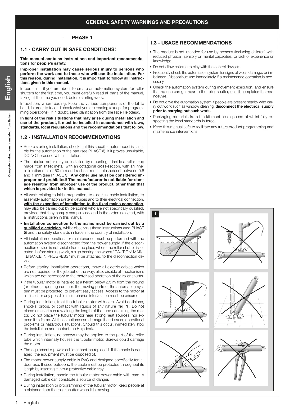
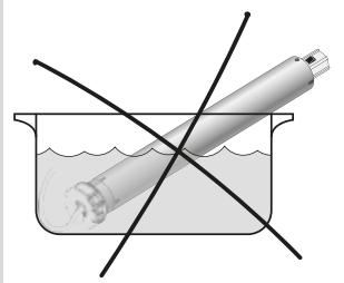
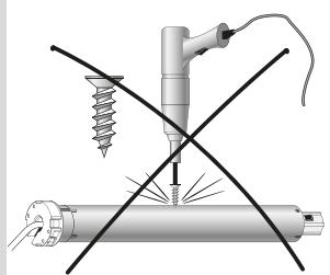
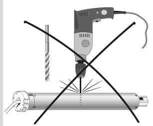
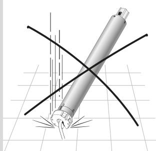
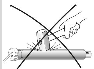
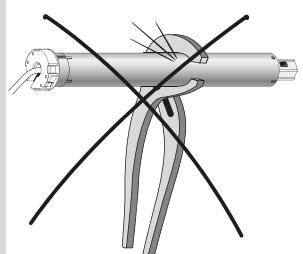
- During installation, treat the tubular motor with care. Avoid collisions, shocks, drops, or contact with liquids of any nature (fig. 1). Do not pierce or insert a screw along the length of the tube containing the motor. Do not place the tubular motor near strong heat sources, nor expose it to flame. All these actions can damage it and cause operational problems or hazardous situations. Should this occur, immediately stop the installation and contact the Helpdesk.
- During installation, no screws may be applied to the part of the roller tube which internally houses the tubular motor. Screws could damage the motor.
- The equipment's power cable cannot be replaced. If the cable is damaged, the equipment must be disposed of.
- The motor power supply cable is PVC and designed specifically for indoor use. If used outdoors, the cable must be protected throughout its length by inserting it into a protective cable tray.
- During installation, handle the tubular motor power cable with care. A damaged cable can constitute a source of danger.
- During installation or programming of the tubular motor, keep people at a distance from the roller shutter when it is moving.
1.3 - USAGE RECOMMENDATIONS
- The product is not intended for use by persons (including children) with reduced physical, sensory or mental capacities, or lack of experience or knowledge.
- Do not allow children to play with the control devices.
- Frequently check the automation system for signs of wear, damage, or imbalance. Discontinue use immediately if a maintenance operation is necessary.
- Check the automation system during movement execution, and ensure that no one can get near to the roller shutter, until it completes the manoeuvre.
- Do not drive the automation system if people are present nearby who carry out work such as window cleaning; disconnect the electrical supply prior to carrying out such work.
- Packaging materials from the kit must be disposed of whilst fully respecting the local standards in force.
- Keep this manual safe to facilitate any future product programming and maintenance interventions.
1
PHASE 2
2.1 - PRODUCT DESCRIPTION AND APPLICATION
This kit consists of a tubular motor and various components, all exclusively designed for automation of roller shutters. Any other use is prohibited! The manufacturer is not liable for damage resulting from improper use of the product, other than that which is provided for in this manual.
The tubular motor is formed mainly of a "motor" part, an electronic logic which supplies the motor and controls execution of manoeuvres.
The tubular motor, through the use of adapters supplied for the purpose, is installed by mounting it on the interior of the roller tube and the whole is then affixed to the inside of the case (located above the roller shutter) using the supplied components.
The motor has command logic (integrated) with electronic limit switch which halts movement of the roller shutter when the motor reaches the following positions: the position when it completes the upward movement (maximum opening: in the manual this is called "limit switch 0") and the position when it completes the downward movement (maximum closure: in the manual this is called "limit switch 1"). The two limit switch points are stored in the command logic with a simple programming procedure. After limit switch programming, sending a command via the control transmitter will activate the roller shutter movement, which will stop automatically when the stored "limit switch point" has been reached.
2.2 - COMPONENTS CONTAINED IN THE KIT
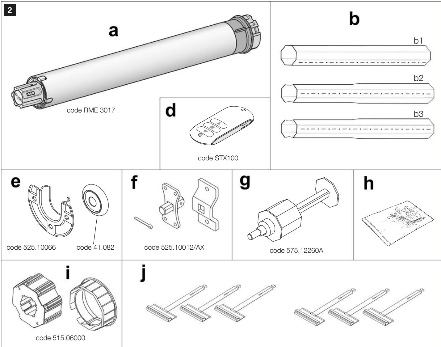
Important! - Before proceeding with the installation, it is necessary to check the integrity of the components present in the RMEKIT AXS 3017 kit and familiarise yourself with their names. This kit includes the following components (fig. 2):
[a] - Tubular motor (Ø 45 mm): code RME 3017
[b] - 60 mm octagonal tube, 1 standard (b1) and 2 telescopic extensions (b2, b3).
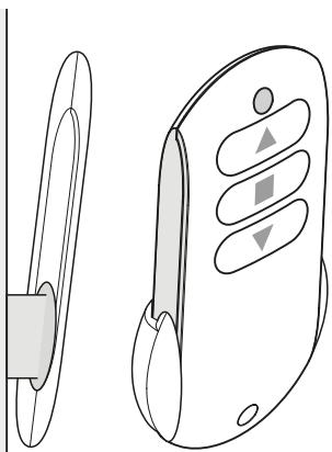
[d] - Transmitter to command the one shutter or a group of roller shutters: code STX100.
[e] - Roller and its support ( 042mm ): code 525.10066 and 41.082
[f] - Motor head support with 4 special screws to fix the motor head: code 525.10012/AX.
[g] - Octagonal telescopic cap (60 mm): code 575.12260A.
[h] - Small metal parts (screws, washers, etc.).
[i] - Motor adaptor set for 60 mm octagonal tube: code 515.06000.
[j] - Six fasteners for roller shutter.
3.1 - PRE-INSTALLATION CHECKS
Important! - Before proceeding with the installation, it is necessary to check that this motor model is suited to the characteristics of the roller shutter to be automated and that it is compatible with the installation environment. Therefore, carry out the following checks:
- Define the material of your roller shutter.
-
- Calculate the surface area of the roller shutter (length x height = m².....?)
-
- Check in Table A if the motor is compatible with your roller shutter. CAUTION! - If the motor is not appropriate, halt the installation and contact the Helpdesk.
| Table A | Max. m² ↓ | |||
| Material ↓ | 2.8 | 5 | 5.6 | 10 |
| Wood | OK | NO! | ||
| PVC/Aluminium | OK | |||
3.1.1 -Warnings
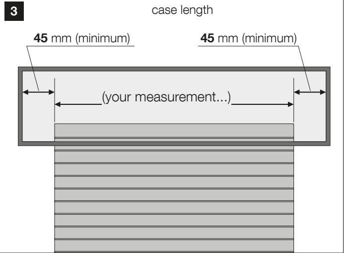
- This tubular motor can automate a roller shutter where the length of the case (the closed housing containing the roller tube which is located above the window) is 90mm longer than the roller shutter width (fig. 3).
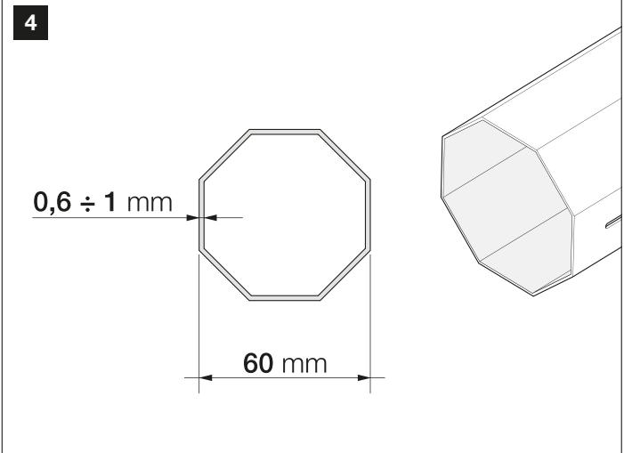
- The tubular motor can only be installed to the interior of a sheet metal roller tube, with octagonal cross-section (with an inner circle diameter of 60mm ) and an included sheet thickness between 0.6 and 1mm (fig. 4).
-
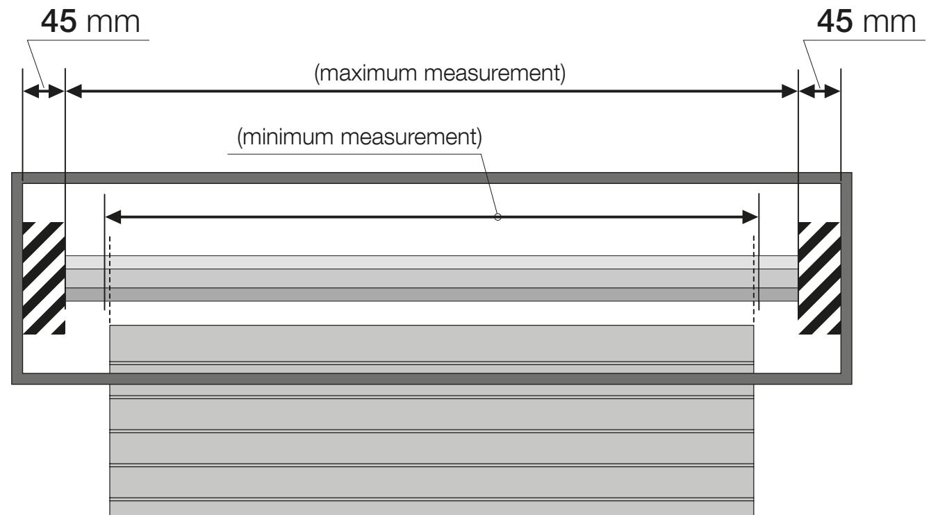
The length of the roller tube must be calculated taking into account the following advised minimum and maximum limits:
-
the minimum length must be, where possible, slightly greater than the length of the roller shutter to be automated;
- the maximum length must be equal to the length of the existing case less 90 mm.
Allow 45mm at each end of the tube (fig. 5).
Details of RMEKIT AXS 3017 Kit lifting capacity
Note that RMEKIT AXS 3017 kit allows motorisation of a roller shutter whose carriage weight is 55kg maximum for a height of 2500mm maximum. These lifting capacities do not take into account any excessive friction that may occur.
5
PHASE 4
4.1 - AUTOMATION COMPONENTS INSTALLATION
The installation operations described in this phase may also be carried out by unqualified personnel, provided that they comply scrupulously and in the order indicated, with the instructions given.
Caution! - Improper installation may cause serious injury to the person who performs the work and to those who will use the installation.
-
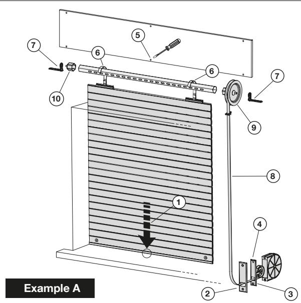
Disassemble the various components from the existing shutter by following the numerical order given in "example A" whilst taking into account the following RECOMMENDATIONS:
-
Before starting work, fully lower the roller shutter.
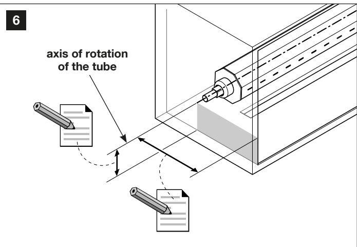
- Before removing the tube, you must locate the exact point of its axis of rotation, by measuring and recording the two measurements shown in fig. 6.
-
Do not remove the shutter from its guides; leave the shutter lowered during all successive component installation phases.
-
Determine the position of the axis of rotation of the tube. - The new tube must be installed in the same position as the preceding tube, using the measurements taken during removal of the existing shutter (fig. 6).
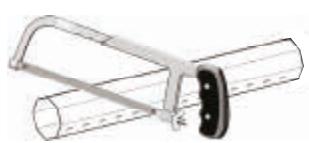
- If a single tube length is sufficient, cut it to length if necessary. - Cut the tube carefully on the basis of the previously determined tube length (see Phase 3), without distorting its end profile.
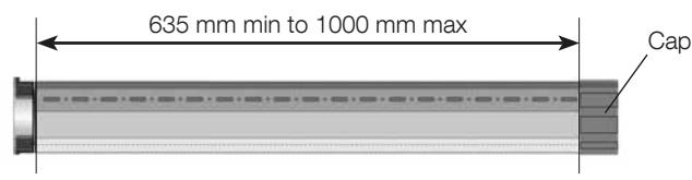
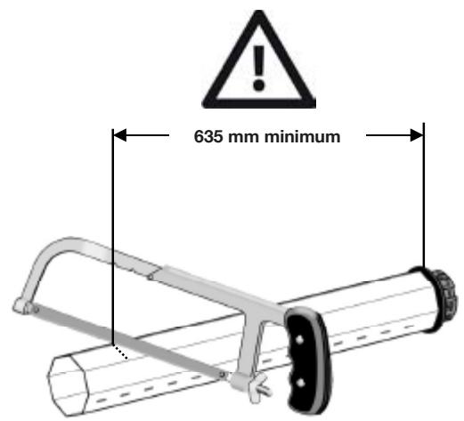
Caution! - In order not to damage the motor fitted within the tube and to enable the cap to be inserted, the length of the tube fitted with the motor, if it must be cut, must never be less than 635mm .
- If a single tube length is not sufficient. After determining the total length of the roller tube by referring to the information shown on page 3, proceed with assembly of the octagonal tube sections. The cut tube sections must respect the recommendations above.
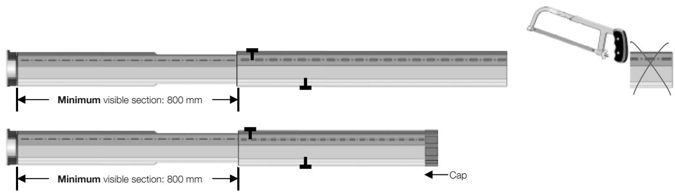
- For a tube length between 635 ~mm and 1000 ~mm
Cut the standard tube to size, do not have a dimension less than 635 mm. Insert the cap.
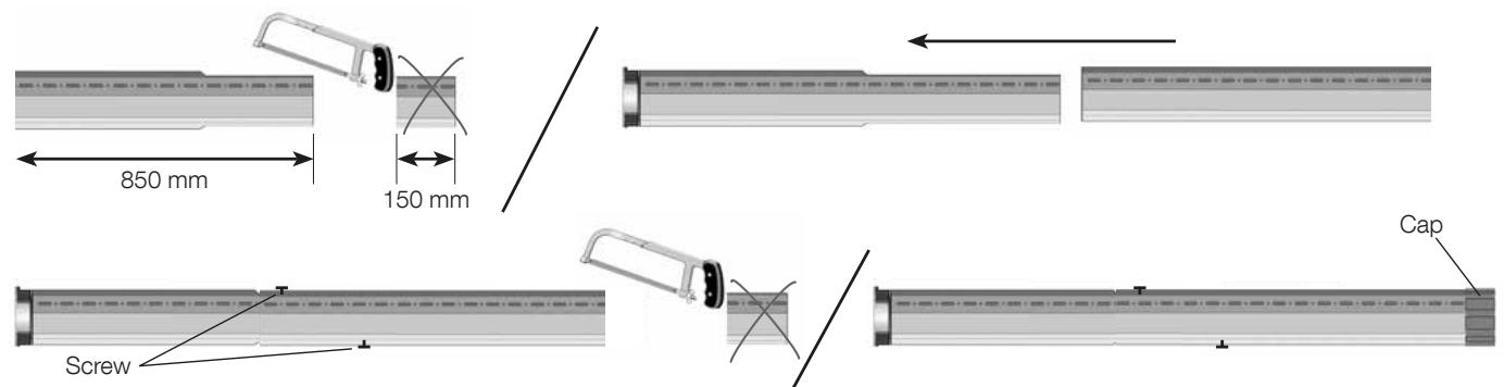
- For a tube length between 1001 ~mm and 1580 ~mm
Cut the telescopic tube by 150 mm on the narrow side. The length obtained is 850 mm. Assemble the standard tube with the cut telescopic tube. Lock the tubes using the 2 self-tapping screws. Then cut the tube obtained to the total desired length. Insert the cap.
- For a tube length between 1581 mm and 1800 mm
Use the full telescopic tube and assemble it with the standard tube. Ensure that the telescopic tube has a minimum visible section of 800~mm . Lock the tubes using the 2 self-tapping screws. Then cut the tube thus obtained to the total desired length. Insert the cap.
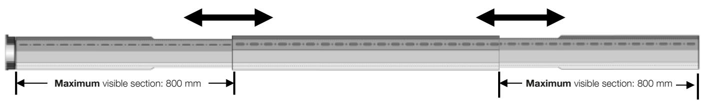
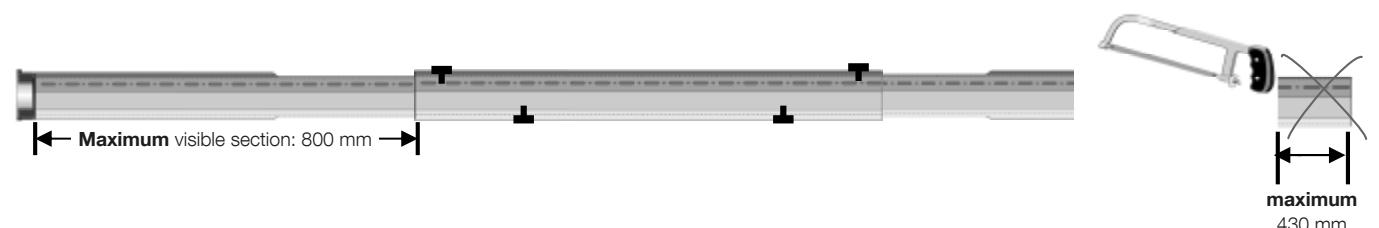
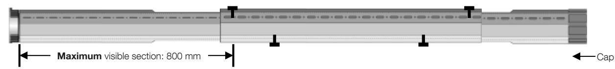
- For a tube length between 1801 ~mm and 2600 ~mm
Use the two full entire telescopic tubes and assemble them with the standard tube. Adjust the two telescopic tubes to obtain the total desired length. Ensure that the telescopic tubes have a maximum visible section of 800mm . Lock the tubes using the 2 self-tapping screws. If necessary, cut the tube opposite the motor by a 430mm maximum to obtain the total desired length. Insert the cap.
7
8
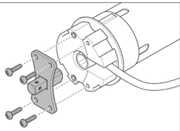
05a. Fixing the motor head. On the motor head, affix the butterfly flange (Fig. 8).
Caution! - Position the square pivot facing outwards.
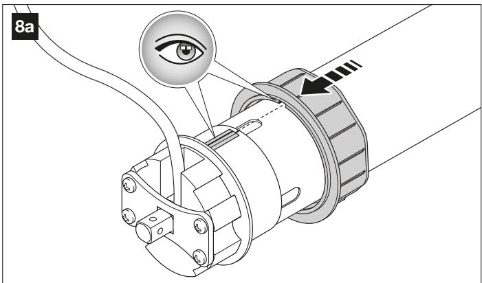
05b. Thread the octagonal crown over the motor tube and push it, as far as the motor head (fig. 8a). Important - slide the crown groove into the protrusion found on the bushing of the limit switches.
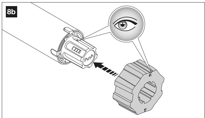
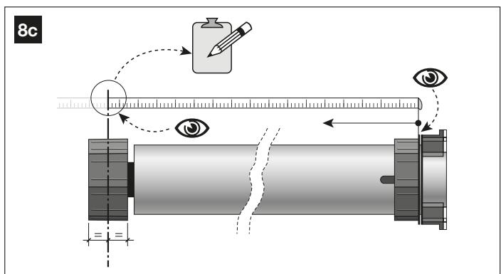
05c. Fit the drive wheel to the self-locking mechanism on the motor shaft, by matching up the two arrows on the two devices (fig. 8b). Note - if you wish to disconnect the wheel, press the "Push" button and extract it.
Measure the motor as shown in fig. 8c.
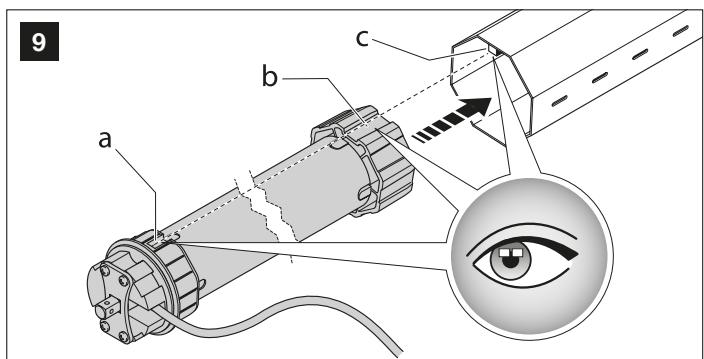
05d. (fig. 9) Align the adapter groove (a), with that on the drive wheel (b). Then insert the motor into the roller tube, by sliding the two grooves a and b in relation to the protrusion (c) found inside the roller tube.
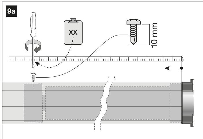
05e. (fig. 9a) Screw the supplied screw (self-tapping 3.9 × 13 , UNI 8118) into the tube, at the point where the drive wheel is located inside the tube (use the measurement carried out in fig. 8c). This step enables the wheel to be correctly locked with the tube.
Caution! - To determine the exact point to place the screw, measure as shown below.
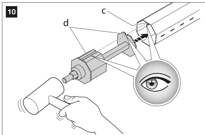
- At the other end, insert the telescopic cap into the tube (fig. 10). During the operation, align groove (d) found on the cap with the groove (c) found inside of the roller tube.
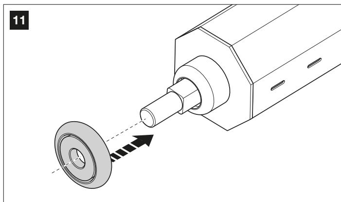
- Insert the roller on to the pivot of the telescopic cap (fig. 11).
- The tube is now ready to be installed in the case. Caution! - Before continuing, ensure that the shutter is fully within the edge guides and that the shutter is completely lowered.
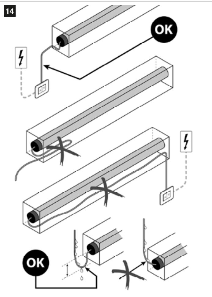
- Choose the side on which to position the motor head. - For safety reasons, the motor head and power cable must be positioned on the side on which the mains power supply is located (fig. 14).
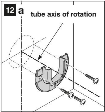
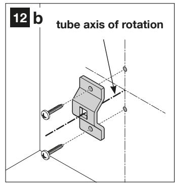
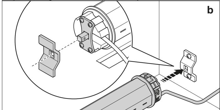
- Fix the supports intended for the telescopic cap (fig. 12a) and the motor head (fig. 12b), to the position determined in point 02 (fig. 6). Screws not supplied.
Caution! - When cutting, ensure that the tube profiles are not deformed at their extremities.
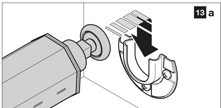
- Install the tube (with the motor) on the supports as follows. Warning! - During the operations, the tube (and the engine) must not be tilted but must always be kept horizontally.
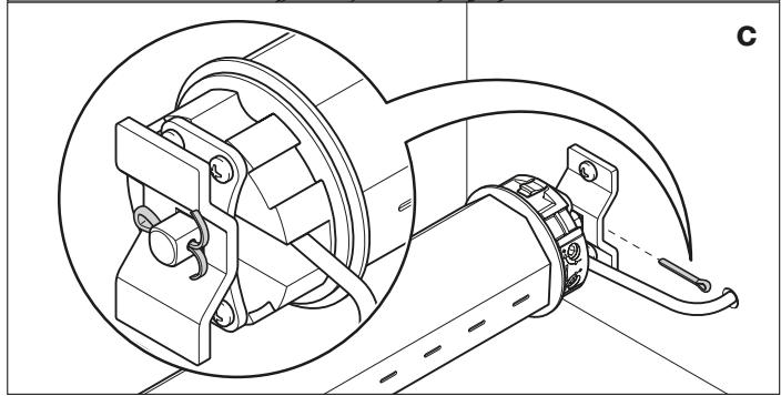
a) slide the roller into the support interior (fig. 13a).
b) insert the square pivot into the support (fig. 13b);
c) finally, thread the metal pin into the square pivot and bend one end so that it does not unthread (fig. 13c).
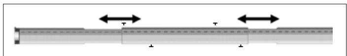
Caution! - If the tube does not enter into the right and left supports, it is possible to remove the locking screws, adjust the length of the telescopic tube(s), then re-lock the tubes using the locking screws.
12. Carefully position and affix the power cable to the inside of the case, in its final position. Caution! - linside the case, the power cable must be placed far away from moving parts (fig. 14).
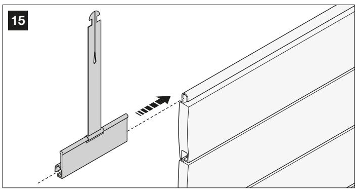
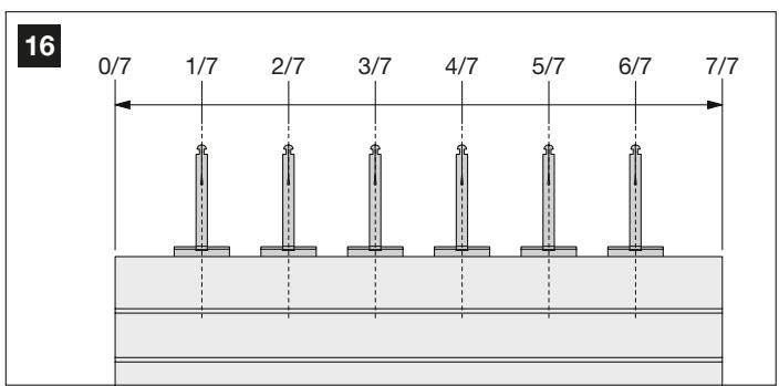
13. Insert the six elements to secure the shutter to the roller, in the free channel of the first plank (top) of the shutter (fig. 15) and position them as follows: measure the carriage length, divide this measurement into 7 equal parts and position the carriage attachments at around 1/7 , 2/7 , 3/7 , 4/7 , 5/7 , 6/7 of the length of the apron (fig. 16).
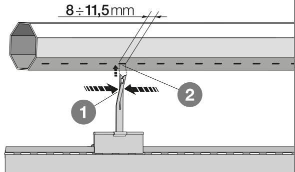
- Fix the six elements to the tube, as shown in fig. 17.
A) Overlap the metal blades.
B) Insert them into the tube slot by a few mm.
C) Release the metal blades.
17
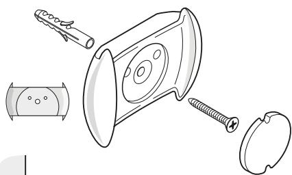
INSTALLATION OF CONTROL TRANSMITTER SUPPORT TO WALL
- To attach the support to the wall, use the adhesive supplied (if the surface is smooth and compact), or use the screw and plug (fig .18).
18
PHASE 5
5.1 - CONNECTION OF THE AUTOMATION SYSTEM TO THE ELECTRIC GRID
CAUTION! - Connection operations described in this phase must be carried out by a qualified electrician, whilst observing these instructions and the safety standards in force in the country of installation.
CAUTION! - Scrupulously respect the connections shown in this manual; an incorrect connection can cause failures or hazardous situations.
The motor's power cable comprises 3 conductors:
(1) - brown wire, for connection to "Phase";
(2) - blue wire, for connection to "Neutral".
(3) - yellow-green wire, for connection to "Earth".
To make all the electrical connections, refer to the following figure:
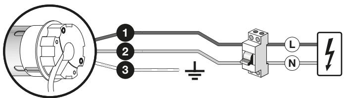
5.1.1 - Installing protective devices on the electrical power supply line
In accordance with rules for the electrical installations, the electric grid supplying the motor must include a short-circuit protection device and a device to disconnect from the electric grid.
CAUTION! - The disconnection device must enable complete disconnection from the power supply, under the conditions determined by overvoltage category III.
The disconnection device must be placed near the automation system and, if it is not visible, a system must be included to prevent any accidental, unauthorised reconnection to the power supply to avoid any hazardous situations.
Note - The two devices are not included in the package.
5.1.2 - First commissioning and electrical connections checks
When the electrical connections are complete, before continuing, you must immediately check that the connections have been carried out correctly, and therefore that the installation works.
To do this, carry out the following operations:
- Switch on the automation system.
- At the same time, check whether the motor makes 2 short movements (the direction of rotation is not important): the 2 short movements confirms that the automation system is properly connected.
PROGRAMS
PHASE 6
6.1 - IMPORTANT NOTES RELATING TO PROGRAMMING THE MOTOR
6.1.1 - Transmitter to use for the programming procedures
- The programming procedures can only be carried out using a Nice Home transmitter with at least the , , buttons.
- The programming procedures must be only be carried out with a transmitter programmed using procedure A (or D).
- If the transmitter used for programming controls several groups of automation systems, during one procedure, before sending a command, you must select the "group" to which the automation system being programmed belongs.
6.1.2 - Positions where the roller shutter stops automatically
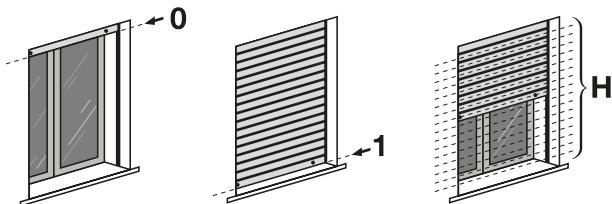
The electronic system that controls the shutter movement is able to stop the movement independently when the shutter reaches a pre-determined position programmed by the installer. The programmables positions are:
position "0" = top limit switch, shutter completely rolled up.
- position "1" = bottom limit switch, shutter completely unrolled.
position "h" = intermediate position, shutter partially rolled up.
Until the limit switches have been programmed, the shutter movement can only take place with a person present, in other words by holding down the control button for the duration of the desired manoeuvre, the movement stops as soon as the user releases the button. On the other hand, after the limit switches have been programmed, simply pressing the desired button will start the shutter; the movement it will stop independently as soon as the shutter reaches the expected limit switch.
6.2 - PROGRAMMING PROCEDURES
A - Storing the FIRST transmitter
IMPORTANT! - This procedure can only be manipulated if the motor does not have any other transmitter stored.
The procedure automatically associates a command given to each button present on the transmitter using the following series criteria:
- button▲: associated with the Upward command
- button ■: associated with the Stop command
- button▼: associated with the Downward command
Before you begin the procedure, place the shutter half way.
- Isolate the motor power supply; wait 2 seconds and restore power to the motor ^(*) : the motor will make 2 movements and remain in standby for an unlimited time.
- Hold the button down and wait for the motor to make 3 movements. After this, release the button.
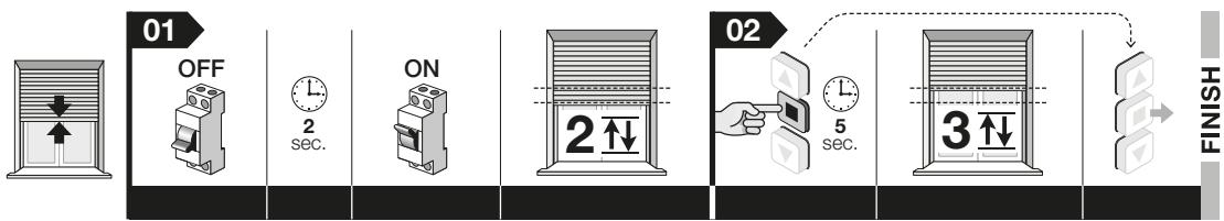
(^*) - Each time the motor receives power, if at least one transmitter and the limit switch points have not been stored in its memory, it makes 2 movements.
B - Manually set the top ("0") and bottom ("1") limit switch points
Warnings - The procedure can be carried out several times without the need to first clear the previous stop positions. - Each time the motor receives power, if at least one transmitter and the limit switch points have not been stored in its memory, it makes 2 movements.
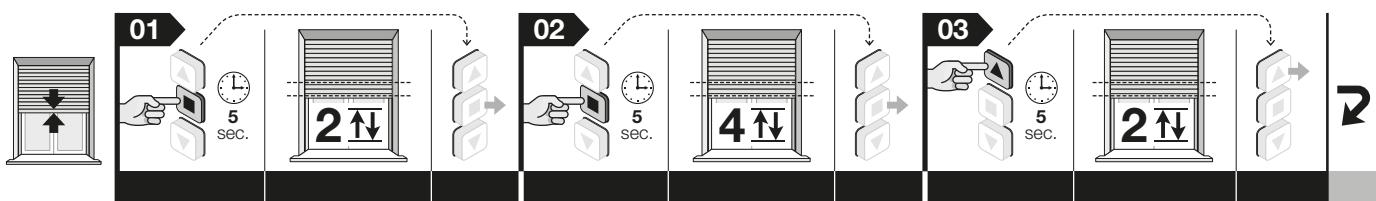
B.1 - To set the top ("0") limit switch
Before you begin the procedure, place the shutter half way (note - if the limit switches are not present the motor makes 2 movements).
- Hold the button down and wait for the motor to make 2 movements. After this, release the button.
- Hold the button down and wait for the motor to make 4 movements. After this, release the button.
- Hold the button down and wait for the motor to make 2 movements. After this, release the button.
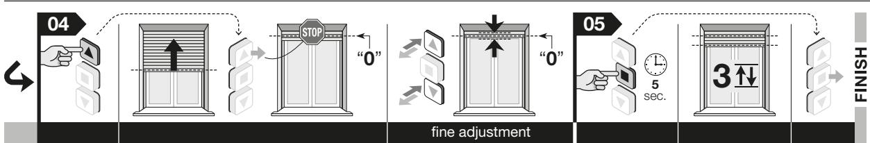
- Set the position: hold down the (or ) button until the shutter reaches the desired "0" position. Note - to set the position accurately, press the and buttons briefly (with each pulse, the shutter moves a few millimetres).
- Hold the button down and wait for the motor to make 3 movements. After this, release the button.
Note - While this procedure is being carried out, you can cancel the programming at any time by simultaneously holding down the and buttons for 4 seconds. Alternatively, do not press any buttons and wait 60 seconds for the motor to make 6 movements.
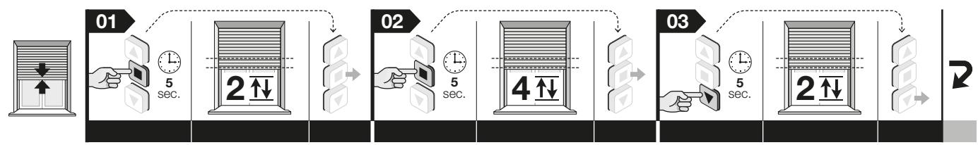
B.1 - To set the bottom ("2") limit switch
Before you begin the procedure, place the shutter half way (note - if a limit switch is not present, the motor makes 1 movement).
01. Hold the button down and wait for the motor to make 2 movements. After this, release the button.
02. Hold the button down and wait for the motor to make 4 movements. After this, release the button.
03. Hold the button down and wait for the motor to make 2 movements. After this, release the button.
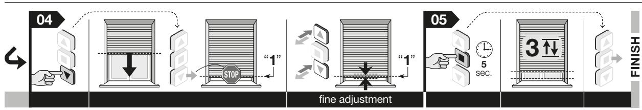
04. Set the position: hold down the (or ) button until the shutter reaches the desired "1" position. Note - to set the position accurately, press the and buttons briefly (with each pulse, the shutter moves a few millimetres).
05. Hold the button down and wait for the motor to make 3 movements. After this, release the button.
Note - While this procedure is being carried out, you can cancel the programming at any time by simultaneously holding down the and buttons for 4 seconds. Alternatively, do not press any buttons and wait 60 seconds for the motor to make 6 movements.
After adjustment, the button will control raising and the button will control lowering. The shutter will move within the limits defined by the two limit switch points.
C - Setting the "H" point, by partial opening/closure
The motor allows you to store up to 30 different positions for partial shutter opening/closure. These "H" points can only be set after setting the "0" and "1" limit switches. The following procedure allows you to set a single "H" point. Repeat the procedure to store the other "H" points.
Warning - If you wish to change the "H" point previously stored, repeat this procedure, pressing on the button associated with the point at step 06.
Before you begin this procedure, place the shutter at the "H" point to be stored.
- Hold the button down and wait for the motor to make 2 movements. After this, release the button.
- Hold the button down and wait for the motor to make 4 movements. After this, release the button.
- simultaneously hold down the and buttons and wait for the motor to make 2 movements. After this, release the button.
- Fine adjustment of the "H" position: press the and buttons briefly to move the shutter to the desired partial point (with each pulse, the shutter moves a few millimetres).
- Hold the button down and wait for the motor to make 3 movements. After this, release the button.
- To store the FIRST "H" point: On the transmitter used for this procedure simultaneously hold down the and buttons and wait for the motor to make 4 movements. After this, release the button.
To store SUBSEQUENT "H" points: on a new transmitter, not stored, hold down the desired button and wait for the motor to make 4 movements. After this, release the button.
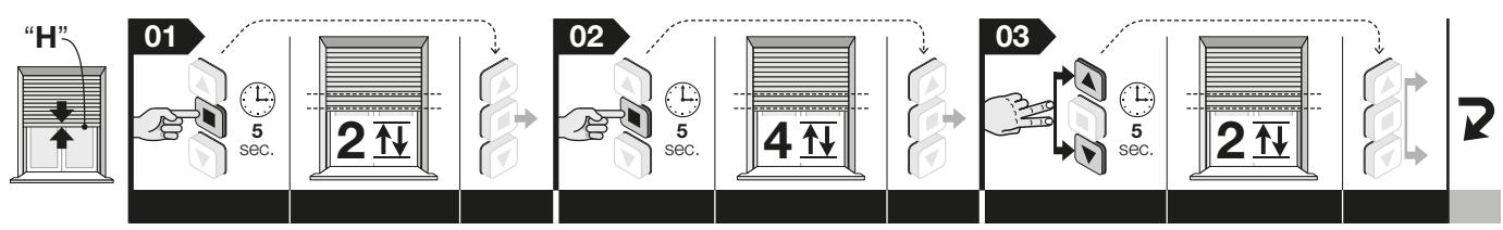
Note - While this procedure is being carried out, you can cancel the programming at any time by simultaneously holding down the and buttons for 4 seconds. Alternatively, do not press any buttons and wait 60 seconds for the motor to make 6 movements.
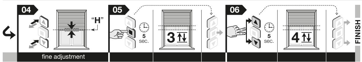
D - Storing an ADDITIONAL transmitter
IMPORTANT! - This procedure can only be carried out if the motor is already associated with a transmitter. To carry out the procedure, you must have access to a second transmitter that has already been stored.
The procedure automatically associates a command given to each button present on the transmitter using the following series criteria:
- button : associated with the Upward command
- button: associated with the Stop command
- button : associated with the Downward command
Before you begin this procedure, place the shutter half way.
- (on the new transmitter) Hold down the button for 8 seconds and release (in this case the motor does not make any movement).
- (on the old transmitter) press the button 3 times, as long as it has been stored.
- (on the new transmitter) Press the button once. After a short time, the motor makes 3 movements to confirm storage. Caution! - If the motor makes 6 movements, this means that its memory is full.
Note - While this procedure is being carried out, you can cancel the programming at any time by simultaneously holding down the and buttons on the old transmitter, for 4 seconds.
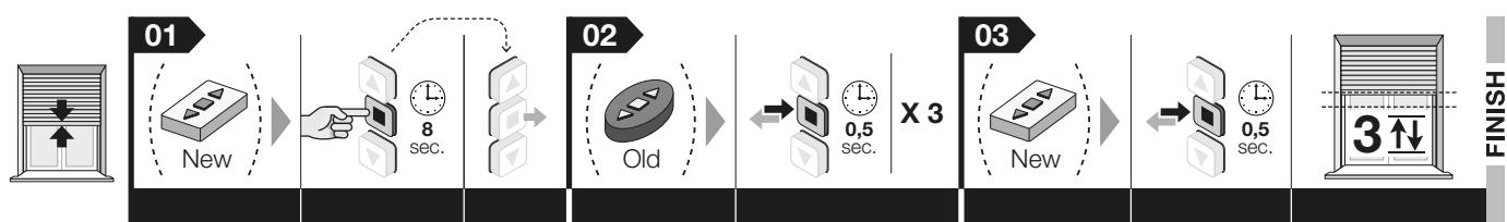
E - Total memory deletion
Before you begin this procedure, place the shutter half way.
- Hold the button down and wait for the motor to make 2 movements. After this, release the button.
- Hold the button down and wait for the motor to make 3 movements. After this, release the button.
- Hold the button down and wait for the motor to make 3 movements. After this, release the button.
- Hold the button down and wait for the motor to make 3 movements. After this, release the button.
- Simultaneously hold down the and buttons and wait for the motor to make 5 movements. After this, release the button.
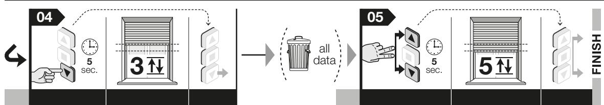
Note - While this procedure is being carried out, you can cancel the programming at any time by simultaneously holding down the and buttons for 4 seconds. Alternatively, do not press any buttons and wait 60 seconds for the motor to make 6 movements.
RECOMMENDATIONS FOR USE OF THE AUTOMATION SYSTEM
MAXIMUM NUMBER OF WORK CYCLES
The motor is intended for domestic purposes, not for intensive use. As a result, in the event of overheating – for instance, due to continued actuation – a safety function ("thermal safety protection" function) automatically intervenes by cutting off the electrical power supply and subsequently reconnecting it once the temperature returns to normal values. In all cases, a continuous working time of 4 minutes maximum is ensured.
- COMMANDING SHUTTER PARTIAL OPENING/CLOSURE ("H" POINT)
In general, to command shutter partial opening/closure, press the button which was associated with the partial point during programming (for more information see step 06 in procedure C). If the transmitter only has one button and a single "H" point has been stored, simultaneously press the
and buttons to call up this point.
WHAT TO DO IF...
(guide to problem resolution)
- When the electric phase is supplied, the motor does not move:
By excluding the possibility that thermal protection is active, in which case simply wait for the motor to cool down, check that the mains voltage corresponds to the data contained in this manual's technical specifications, by measuring the "common" energy level and the supplied phase power. Then try the opposite electrical phase.
□ When a raise command is sent, the motor does not start:
This may occur if the shutter is near the Top ("0") limit switch point. In this case, firstly lower the shutter a short distance and then repeat the upward command.
The system operates under emergency conditions (with a person present):
-
Check if the motor has suffered a strong electric or mechanical shock.
-
Check that each part of the motor is present.
Carry out the procedure to delete (procedure E) and re-set the limit switches (procedure B).
TECHNICAL CHARACTERISTICS
WARNINGs • All technical characteristics shown refer to an ambient temperature of 20^ (± 5^) • Nice S.p.a. reserves the right to make changes to the product when it deems this necessary, whilst guaranteeing the same functions and usage for which the product is intended.
- Power supply voltage and frequency; Current and power;
Torque and speed: See technical data on the label on the motor
Encoder resolution: 2.7^
Continuous operation nominal duration: maximum 4 minutes - Degree of protection: IP 44
Minimum operating temperature: -20^
PRODUCT DISPOSAL
This product is an integral part of the automation system and must therefore be scrapped with the rest of the latter.
As for installation, at the end of the life of this product, the dismantling operations must be carried out by qualified personnel. This product is made from different types of materials: some may be recycles, others must be scrapped. Research the recycling or disposal systems provided by the standards in force in the country for this product category. Caution! - some components of the product may contain polluting or hazardous substances, which could have harmful effects on the environment, and on
the health of persons, if not properly disposed of. As indicated by the symbol shown, it is forbidden to discard this product in household refuse collection facilities. Proceed to "separate collection" of the components, to ensure their management in

accordance with the methods laid down by local standards in force, or return the product to the seller when purchasing a new equivalent product. Caution! – the local regulations in force may impose heavy penalties in the event of prohibited disposal of this product.
- Packaging materials from the product must be disposed of whilst fully respecting the local standards in force.
DECLARATION OF CONFORMITY
Declaration compliant with Directive 1999/5/EC
NOTE - The content of this declaration corresponds to that specified in the official document deposited at the Nice S.p.a. headquarters and, in particular, to the latest revised edition available prior to the publishing of this manual. The text herein has been re-edited for editorial purposes. A copy of the original declaration can be requested from Nice S.p.a. (TV) I.
Declaration number: 596/RME Revision: 0 Language: EN
The undersigned Roberto Griffin, as Chief Executive Officer, hereby declares under his own responsibility that the product:
Manufacturer's name: NICE S.p.A.
- Address: Via Pezza Alta N°13, 31046 Rustignè di Oderzo (TV) Italy
- Type of product: Tubular motor for roller shutters and awnings
Model / Type: RME 3017
- Accessories: none.
complies with the essential provisions of article 3 of the community Directive below, for the usage for which the product is intended:
- Directive 1999/5/EC OF THE EUROPEAN PARLIAMENT AND COUNCIL of 9 March 1999 on radio equipment and telecommunications terminals and mutual recognition of their conformity, according to the following harmonised standards:
- Protection of health (art. 3(1)(a)): EN 62479:2010
- Electrical safety (art. 3(1)(a)): EN 60950-1:2006 + A11:2009 +
A12:2011 + A1:2010 + A2:2013 - Electromagnetic Compatibility (art. 3(1)(b)): EN 301 489-1
V1.9.2:2011; EN 301 489-3 V1.6.1:2013
- Radio Spectrum (art. 3(2)): EN 300 220-2 V2.4.1:2012
Furthermore, the product complies with the provisions of the following community Directives:
- DIRECTIVE 2014/35/EU OF THE EUROPEAN PARLIAMENT AND COUNCIL of 26 February 2014 on the approximation of the laws of Member States relating to the making available on the market of electrical equipment designed for use within certain voltage limits (recast), according to the following harmonised standards: EN 60335-1:2002 + A1:2004 + A11:2004 + A12:2006 + A2:2006 + A13:2008 + A14:2010 + A15:2011; EN 60335-2-97:2006 + A11:2008 + A2:2010 + A12:2015; EN 62233:2008.
- DIRECTIVE 2014/30/EU OF THE EUROPEAN PARLIAMENT AND COUNCIL of 26 February 2014 on the approximation of the laws of Member States relating to electromagnetic compatibility (recast), according to the following harmonised standards: EN 55014-1:2006 + A1:2009 + A2:2011; EN 55014-2:1997 + A1:2001 + A2:2008 ; EN 61000-3-2:2014 ; EN 61000-3-3:2013.
Oderzo, 28 July 2016
Ing. Roberto Griffin
(Chief Executive Officer)
—FASE1
(Aministratore Delegation)