90 - Induction ELAN - Free user manual and instructions
Find the device manual for free 90 ELAN in PDF.

| Product type | Induction cooker with ovens |
| Brand and model | ELAN 90 |
| Cooking type | Induction |
| Number of burners | 5 |
| Dimensions (H x W x D) | 902-927 x 900 x 650 mm |
| Electrical supply | 220-240 V ~ 50 Hz |
| Maximum total power | 18.2 kW at 230 V |
| Grill power | 2.3 kW |
| Main oven volume | 62 litres |
| Top oven volume | 53 litres |
| Main oven energy class | B |
| Top oven energy class | B |
| Main oven consumption | 0.90 kWh |
| Top oven consumption | 0.99 kWh |
| Main oven functions | Defrost, fan-forced, ventilated grill, mixed fan-forced, top/bottom heat, grill element, bottom heat |
| Cooking hob functions | Pan detection, residual heat indicator, automatic heating, child lock |
| Cleaning | Self-cleaning panels, ceramic glass surface |
| Safety | Child lock, pan detection, overheat protection |
Frequently Asked Questions - 90 ELAN
User questions about 90 ELAN
0 question about this device. Answer the ones you know or ask your own.
Ask a new question about this device
Download the instructions for your Induction in PDF format for free! Find your manual 90 - ELAN and take your electronic device back in hand. On this page are published all the documents necessary for the use of your device. 90 by ELAN.
USER MANUAL 90 ELAN
Thank you for buying a Falcon cooker. It should give you many years of trouble-free cooking if installed and operated correctly. It is important that you read this section before you start, particularly if you have not used an induction cooker before.

This appliance is designed for domestic cooking only. Using it for any other purpose could invalidate any warranty or liability claim. In particular, the oven should NOT be used for heating the kitchen – besides invalidating claims this wastes fuel and may overheat the control knobs.
Installation and Maintenance
In the UK the electrical installation should be in accordance with BS 7671. Otherwise, all installations must be in accordance with the relevant instructions in this booklet, with the relevant national and local regulations, and with the local electricity supply companies' requirements.
Make sure that the cooker is wired in and switched on.
The hob control display will flash for about 2 seconds during first power setting – this is normal.
Set the clock to ensure that all the ovens are functional - see the relevant section in this manual.
The cooker should be serviced only by a qualified service engineer, and only approved spare parts should be used.
Always allow the cooker to cool and then switch it off at the mains before cleaning or carrying out any maintenance work, unless specified otherwise in this guide.
Peculiar Smells
When you first use your cooker it may give off a slight odour. This should stop after a little use.
Before using for the first time, make sure that all packing materials have been removed and then, to dispel manufacturing odours, turn the ovens to 200^ and run for an hour.
Before using the grill for the first time you should also turn on the grill and run for 30 minutes with the grill pan in position, pushed fully back, and the grill door open.
Make sure the room is well ventilated to the outside air (see 'Ventilation' below). People with respiratory or allergy problems should vacate the area for this brief period.
Ventilation
The use of a cooking appliance results in the production of heat and moisture in the room in which it is installed. Therefore, ensure that the kitchen is well ventilated: keep natural ventilation holes open or install a powered cooker hood that vents outside. If you have several hotplates on, or use the cooker for a long time, open a window or turn on an extractor fan.
Personal Safety
Important information for pacemaker and implanted insulin pump users: The functions of this hob comply with the applicable European standards on electromagnetic interference. If you are fitted with a pacemaker or implanted insulin pump and are concerned please consult your doctor for medical advice.
When the hob is in use keep magnetic items, such as credit and debit cards, floppy disk, calculators, etc. away.
A Accessible parts will become hot during use and will retain heat even after you have stopped cooking. Keep babies and children away from the cooker and never wear loose-fitting or hanging clothes while the appliance is in use.
Always be certain that the controls are in the OFF position when the oven is not in use, and before attempting to clean the cooker.
Take care when touching the marked cooking areas of the hob.
When the oven is on, DO NOT leave the oven door open for longer than necessary, otherwise the control knobs may become very hot.
Cooking high moisture content foods can create a 'steam burst' when the oven door is opened. When opening the oven stand well back and allow any steam to disperse.
Always keep combustible materials, e.g. curtains, and flammable liquids a safe distance away from your cooker.
DO NOT spray aerosols in the vicinity of the cooker while it is on.
Use dry oven gloves when applicable – using damp gloves might result in steam burns when you touch a hot surface. Do not use a towel or other bulky cloth in place of a glove – it might catch fire if brought into contact with a hot surface.
NEVER operate the cooker with wet hands.
DO NOT use aluminium foil to cover shelves, linings or the oven roof.
NEVER heat unopened food containers. Pressure build up may make the containers burst and cause injury.
English
DO NOT use unstable saucepans. Always ensure that you position the handles away from the edge of the hotplate.
A Make sure to use adequately sized pans with flat bottoms that are large enough to cover the surface of the hotplate heating area.
Never leave the hotplate unattended at high heat settings. Pans boiling over can cause smoking, and greasy spills may catch on fire. Use a deep fat thermometer whenever possible to prevent fat overheating beyond the smoking point.
NEVER leave a chip pan unattended. Always heat fat slowly, and watch as it heats. Deep fry pans should be only one third full of fat. Filling the pan too full of fat can cause spill over when food is added. If you use a combination of oils or fats in frying, stir them together before heating, or as the fats melt.
Foods for frying should be as dry as possible. Frost on frozen foods or moisture on fresh foods can cause hot fat to bubble up and over the sides of the pan. Carefully watch for spills or overheating of foods when frying at high or medium high temperatures. Never try to move a pan of hot fat, especially a deep fat fryer. Wait until the fat is cool.
Do not use the top of the flue (the slot along the back of the cooker) for warming plates, dishes, drying tea towels or softening butter.

DO NOT use water on grease fires and never pick up a flaming pan. Turn off the controls and then smother a flaming pan on a surface unit by covering the pan completely with a well-fitting lid or baking tray. If available, use a multipurpose dry chemical or foam-type fire extinguisher.

This appliance is heavy so take care when moving it.
Hob Care

DO NOT use the hob surface as a cutting board.
Do not leave utensils, foodstuffs or combustible items on the hob when it is not is use (e.g. tea towels, frying pans containing oil).

DO NOT place plastic or aluminium foil, or plastic containers, on the hob.

DO NOT leave the hob zones switched on unless being used for cooking.

NEVER allow anyone to climb or stand on the hob.
Do not stand or rest heavy objects on the hob. Although the ceramic surface is very strong, a sharp blow or sharp falling object (e.g. a salt cellar) might cause the surface to crack or break.
Should a crack appear in the surface, disconnect the appliance immediately from the supply and arrange for its repair.
Always LIFT pans off the hob. Sliding pans may cause marks and scratches. Always turn the control to the OFF position before removing a pan.
DO NOT place anything between the base of the pan and the hob surface (e.g. asbestos mats, aluminium foil, Wok stand).
Care should be taken that no water seeps into the appliance.
Only certain types stainless steel, enamelled steel pans or cast iron pans with enamelled bases are suitable for induction hob cooking.
The ceramic surface should be washed after use to prevent it from becoming scratched or dirty. However, you should clean the hob with caution as some cleaners can produce noxious fumes if applied to a hot surface.
DO NOT use abrasive cleaners/pads, oven aerosols/pads or stain removers on the surface.
We recommend that you avoid wiping any surface unit areas until they have cooled and the indicator light has gone off. Sugar spills are the exception to this (see 'Cleaning your Cooker'). After cleaning, use a dry cloth or paper towel to remove any cleaning cream residue.
Cooker Care
As steam can condense to water droplets on the cool outer trim of the oven, it may be necessary during cooking to wipe away any moisture with a soft cloth. This will also help to prevent soiling and discolouration of the oven exterior by cooking vapours.
Cleaning
In the interests of hygiene and safety, the cooker should be kept clean at all times as a build up in fats and other food stuff could result in a fire.
Clean only the parts listed in this guide.
Clean with caution. If a wet sponge or cloth is used to wipe spills on a hot surface, be careful to avoid steam burns. Some cleansers can produce noxious fumes if applied to a hot surface.
2. Cooker Overview
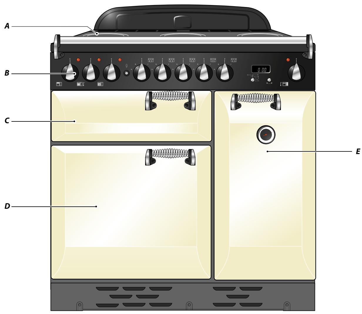
Fig.2-1
The 90 induction cooker (Fig.2-1) has the following features:
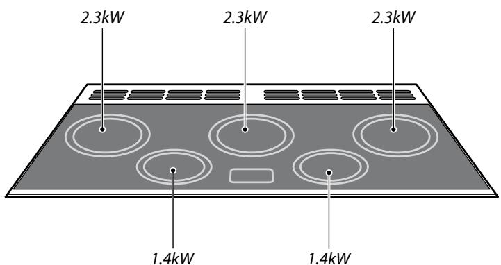
A. 5 induction cooking zones
B. A control panel
C. A glide-out grill
D. Main programmable fan oven
E. Tall fan oven
The Hob
Use only pans that are suitable for induction hobs. We recommend stainless steel, enamelled steel pans or cast iron pans with enamelled bases. Note that some stainless steel pans are not suitable for use with an induction hob so please check carefully before purchasing any cookware.
Pans made of copper, aluminium or ceramic are not suitable for use on an induction hob. The kind of pan you use and the quantity of food affects the setting required. Higher settings are required for larger quantities of food.
Pots and pans should have thick, smooth, flat bottoms (Fig.2-2). This ensures the maximum heat transfer from the hob to the pan, making cooking quick and energy efficient. Never use a round-bottomed wok, even with a stand.
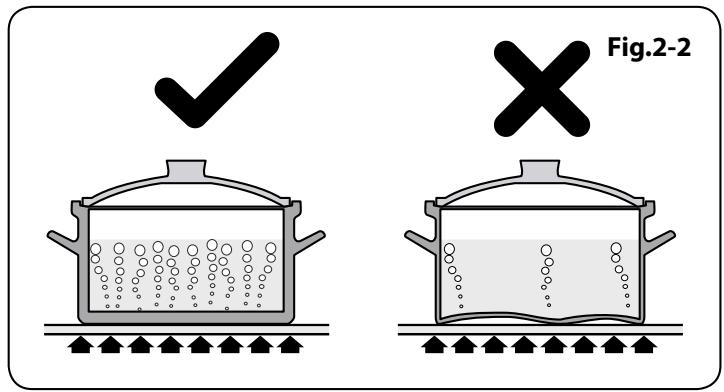
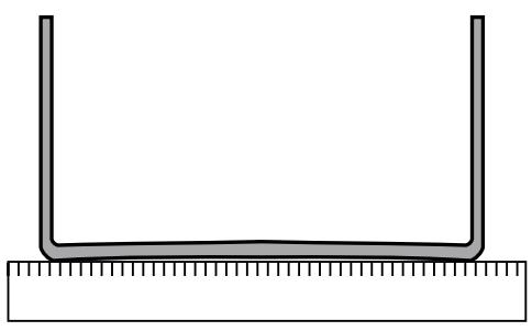
Fig.2-3
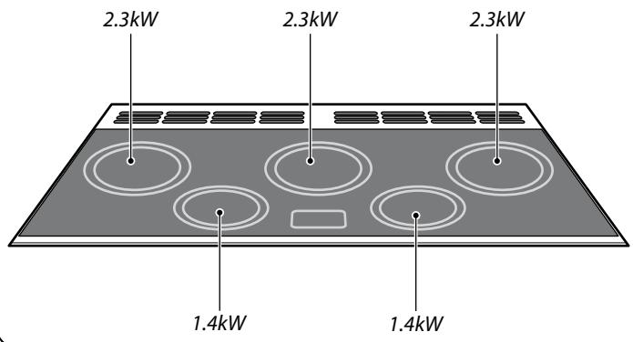
Fig.2-4
Fig.2-5
Table 2-1
| Cooking Zone | Minimum Pan Diameter (Pan base) mm |
| Front left | 140 |
| Rear left | 180 |
| Centre | 180 |
| Rear right | 180 |
| Front right | 140 |
The very best pans have bases that are very slightly curved up when cold (Fig.2-3). If you hold a ruler across the bottom you will see a small gap in the middle. When they heat up the metal expands and lies flat on the cooking surface.
Make sure that the base of the pan is clean and dry to prevent any residue burning onto the hob panel. This also helps prevent scratches and deposits.
Always use pans that are the same size as (or slightly larger than) the areas marked on the hob. Using a lid will help the contents boil more quickly.

Always take care before touching the surface, even when the hob is turned off. It may be hotter than you think!
The induction hob comprises of five cooking zones containing induction elements with different ratings and diameters (Fig.2-4) each with a pan detector and residual heat indicator, and a hob control display.
The hob control display (Fig.2-5) informs you of the following induction hob functions:
Pan detector
H Residual heat indicator
Automatic heat-up
Child lock
Pan Detector,
IMPORTANT: After use, switch off the hob element by its control and DO NOT RELY on the pan detector.
If a cooking area is switched on and there is no pan in place or if the pan is too small for the cooking area, then no heat will be generated. The symbol [] will appear on the hob control display; this is the "pan-missing symbol". Place a pan of the correct size on the cooking area and the [] symbol will disappear and cooking can begin. After 10 minutes without detecting a pan the cooking zone will switch off automatically.
Table 2-1 shows the minimum pan sizes recommended for each cooking zone.
Note: Using pans with a base diameter smaller than those recommended will result in a power reduction.
Residual Heat Indicator, H
After use, a cooking zone will remain hot for a while as heat dissipates. When a cooking zone is switched off the residual heat indicator symbol [H] , will appear in the display. This shows that the cooking zone temperature is above 60^ and may still cause burns. Once the temperature has dropped to below 60^ the [H] will go out.
Automatic Heat-up, R
This function is available on all of the cooking areas. It allows rapid heating up of the element to bring the selected cooking zone up to temperature. Once the zone is at the required cooking temperature the power level will reduce automatically to the preset level.
The function is selected by turning the control knob to the 'A' position. This can be selected by either turning the control knob momentarily anti-clockwise from the zero position or clockwise past the '9' until the symbol [R] is shown on the hob control display. Once the [R] is displayed, turn the control knob to the level of your choice (1 to 9). The pan will heat up at 100% power for a specified time before the power is reduced to the level selected.
When the Automatic Heat-up function is activated, the hob control display will flash alternately between the [R] setting and the chosen power level.
Once the automatic heat-up time has ended the hob control display will stop flashing and will display the chosen power level.
The Automatic Heat-up function can be stopped by either turning the control knob back to the "0" power setting or turning the control knob to the "9" power setting.
For your guidance Table 2-2 shows the time available at 100% power depending on the power level selected in the Automatic Heat-up mode.
Child Lock, L
To prevent the unwanted use by children, the hob can be locked.
IMPORTANT: This can only be activated when all the cooking zones are switched off.
To lock the hob, first turn on any of the hob controls on then off – this will activate the hob display – then simultaneously turn both rear outer induction controls anti-clockwise
(Fig.2-6) until [L] appears in the hob control display for all cooking areas.
This will NOT affect the ovens or grill; they can still be used.
To unlock the hob, simultaneously turn both rear outer induction controls anti-clockwise until the [L] symbol disappears.
Pan Protection Function
This function identifies when the temperature of the pan rises rapidly and works to maintain a safe level of pan temperature. It should not interfere with normal cooking.

Please remember not to leave the hob unattended. Care should be taken to not allow your cookware to boil dry.
The Glide-out Grill
Open the door and pull the grill pan carriage forward using the handle (Fig.2-7).
The grill has two elements that allow either the whole area of the pan to be heated or just the right-hand half.
Adjust the heat to suit by turning the knob. To heat the whole grill, turn the knob clockwise (Fig.2-8).
To heat the right-hand half, turn the knob anti-clockwise. The neon indicator light by the grill control will come on.
| Power Level | Automatic heat-up time at 100% (min:sec) |
| 1 | 0:48 |
| 2 | 2:24 |
| 3 | 3:48 |
| 4 | 5:12 |
| 5 | 6:48 |
| 6 | 2:00 |
| 7 | 2:48 |
| 8 | 3:36 |
| 9 | 0:10 |
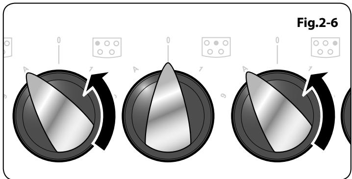
Table 2-2
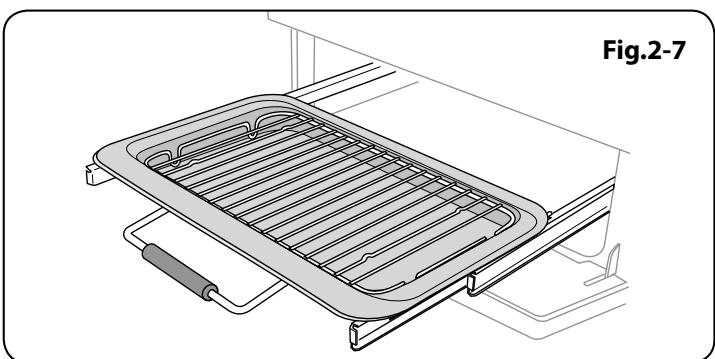
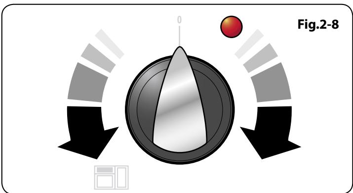
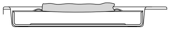
Fig.2-9
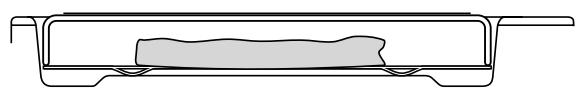
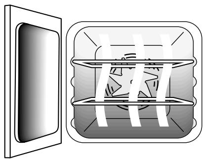
Fig.2-10
For best results, slide the carriage back into the grill chamber and preheat the appropriate part(s) of the grill for two minutes. The grill trivet can be removed and the food placed on it while you are waiting for the grill to preheat.
Once the grill has preheated, slide the carriage out again. With the trivet back in place with the food on it, slide the carriage back into the grill chamber. Ensure that it is pushed right in.

Accessible parts may be hot when the grill is in use. Young children should be kept away.
The grill pan grid can be turned over to give two grilling positions (Fig.2-9).
Do not leave the grill on for more than a few moments, without the grill pan underneath it.

Never close the grill door when the grill is on.
The Ovens
The clock must be set to the time of day before the right-hand oven will work. See the following section on 'The Clock' for instructions on setting the time of day.
References to 'left-hand' and 'right-hand' ovens apply as viewed from the front of the appliance.
The left-hand oven is a programmable multi-function oven, while the right-hand tall oven is a fanned oven.
The Left-Hand Multi-function Oven
The left-hand (Fig.2-10) oven is a multi-function oven. As well as the oven fan and fan element, it is fitted with two extra heating elements, one visible in the top of the oven and the second under the oven base. Take care to avoid touching the top element and element deflector when placing or removing items from the oven.
The multi-function oven has many varied uses. We suggest you keep a careful eye on your cooking until you are familiar with each function (Fig.2-11). Remember – not all functions will be suitable for all food types.
Multi-function oven functions
Defrost

This function operates the fan to circulate cold air only. No heat is applied. This enables small items such as desserts, cream cakes and pieces of meat, fish and to be defrosted.
Defrosting in this way speeds up the process and protects the food from flies. Pieces of meat, fish and poultry should be placed on a rack, over a tray to catch any drips. Be sure to wash the rack and tray after defrosting.
Defrost with the oven door closed.
Large items, such as whole chickens and joints should not be defrosted in this way. We recommend this be carried out in a refrigerator.
Defrosting should not be carried out in a warm oven or when an adjoining oven is in use or still warm.
Ensure that dairy foods, meat and poultry are completely defrosted before cooking.
Fan oven

This function operates the fan and the heating element around it. An even heat is produced throughout the oven, allowing you to cook large
amounts quickly.
Fan oven cooking is particularly suitable for baking on several shelves at one time and is a good 'all-round' function. It may be necessary to reduce the temperature by approximately 10^ for recipes previously cooked in a conventional oven.
If you wish to preheat the oven, wait until the indicator light has gone out before inserting the food.
Fanned grilling

This function operates the fan whilst the top element is on. It produces a more even, less fierce heat than a conventional grill. For best results, place the food
to be grilled, on a grid over a roasting tin, which should be smaller than a conventional grill pan. This allows greater air circulation. Thick pieces of meat or fish are ideal for grilling in this way, as the circulated air reduces the fierceness of the heat from the grill.
The oven door should be kept closed while grilling is in progress, so saving energy.
You will also find that the food needs to be watched and turned less than for normal grilling. Preheat this function before cooking.
Fan assisted oven

This function operates the fan, circulating air heated by the elements at the top and the base of the oven. The combination of fan and conventional cooking
(top and base heat) makes this function ideal for cooking large items that need thorough cooking, such as a large meat roast.
It is also possible to bake on two shelves at one time, although they will need to be swapped over during the cooking time, as the heat at the top of the oven is greater than at the base, when using this function.
This is a fast intensive form of cooking; keep an eye on the food cooking until you have become accustomed to this function.
Conventional oven (top and base heat)

This function combines the heat from the top and base elements. It is particularly suitable for roasting and baking pastry, cakes and biscuits.
Food cooked on the top shelf will brown and crisp faster than on the lower shelf, because the heat is greater at the top of the oven than at the base, as in 'Fan assisted oven' function. Similar items being cooked will need to be swapped around for even cooking. This means that foods requiring different temperatures can be cooked together, using the cooler zone in the lower half of the oven and hotter area to the top.
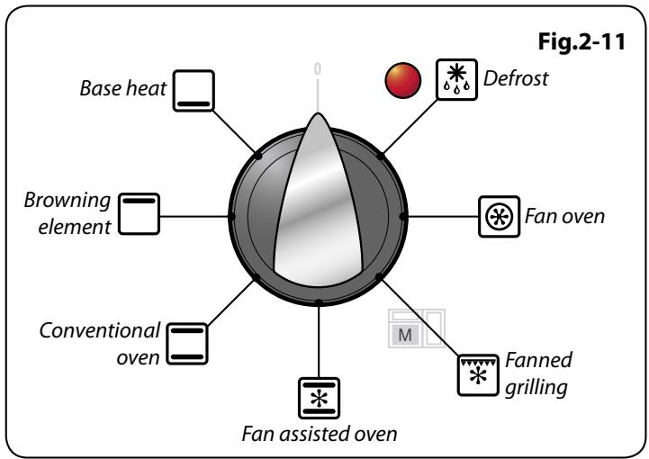
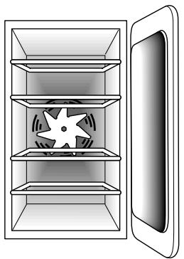
Fig.2-12
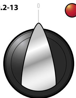
Fig.2-13
Temperature


Function
Fig.2-14

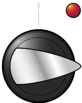


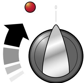
Fig.2-15
Browning element

This function uses the element in the top of the oven only. It is a useful function for the browning or finishing of pasta dishes, vegetables in sauce,
shepherds pie and lasagne, the item to be browned being already hot before switching to the top element.
Base heat

This function uses the base element only. It will crisp up your pizza or quiche base or finish off cooking the base of a pastry case on a lower shelf. It is also
a gentle heat, good for slow cooking of casseroles in the middle of the oven or for plate warming.
The Browning and Base heat functions are useful additions to your oven, giving you flexibility to finish off items to perfection.
Right-hand tall oven
The right-hand tall oven is a fanned oven (Fig.2-12) that circulates hot air continuously, which means faster, more even cooking.
Note: Please remember that all cookers vary so temperatures in your new ovens may differ to those in your previous cooker.
Operating the Ovens
Operating the left-hand multi-function oven
The multi-function oven has two controls: a function selector and a temperature setting knob (Fig.2-13).
Turn the function selector control to a cooking function. Turn the oven temperature knob to the temperature required (Fig.2-14).
The oven heating light will glow until the oven has reached the temperature you selected. It will then cycle on and off during cooking.
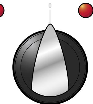
Operating the right-hand fan oven
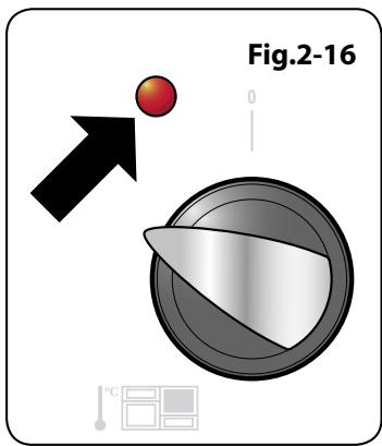
Turn the oven knob to the desired temperature (Fig.2-15).
The oven indicator light will glow until the oven has reached the temperature selected. It will then cycle on and off during cooking (Fig.2-16).
When cooking foods with high water content, there may be some steam visible at the grille at the rear of the hotplate. This is perfectly normal.
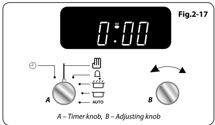
The Clock
Setting the time of day
The LCD clock is shown in (Fig.2-17). When the clock is first connected, the display flashes (0.00) and (~~一~) alternately.
To set the time, turn and hold the Timer knob to the clock symbol (⊙) and at the same time turn the Adjusting knob left or right until the clock shows the time of day. Remember this is a 24-hour clock. Let go of the Timer knob and it will spring back to the vertical, oven manual setting.
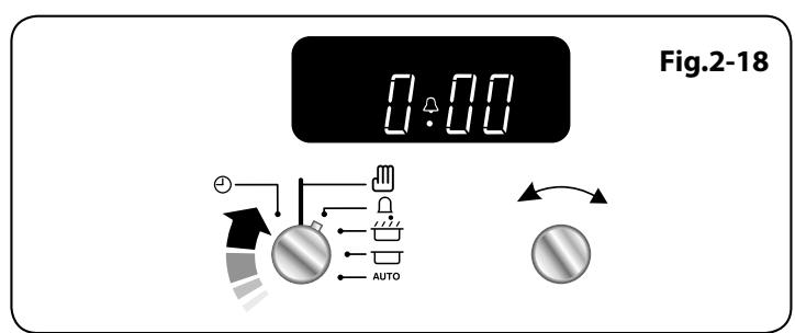
Minute Minder
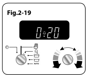
Turn the Timer knob to the right to the (Ω) minute minder setting – it should click into position (Fig.2-18).
Use the Adjusting knob to set the time you need (Fig.2-19).
You can either turn the knob back to the vertical manual setting (凹) to keep an eye on the time of day, or leave it in the (凹) minute minder position as the time ticks down.
To stop the beeper when it sounds, turn the Adjusting knob anti-clockwise.
To stop the left-hand oven at a specific time of day
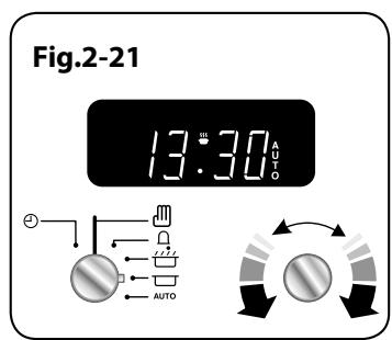
Turn the Timer knob to the () position (Fig.2-20).
Use the Adjusting knob to set the time at which the oven is to stop. You can set the oven to turn on at any time over the following 24-hour period. AUTO shows in the display (Fig.2-21).
Turn the Timer knob to the bottom 'AUTO' setting. Once the set time is reached, the beeper sounds. Turn the Timer knob to the vertical (凹) to return to manual cooking.
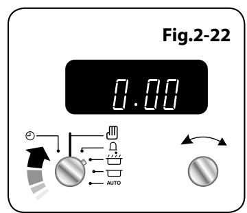
To start and then stop the left-hand oven using the Timer
Before you set the clock, decide on both the 'cook time', which is the period of time you want the oven to cook, and the 'stop time', which is the time of day at which you want the oven to stop cooking.
You cannot set a start time directly – this is set automatically by a combination of the 'cook time' and 'stop time'.
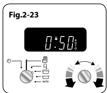
Turn the Timer knob to the ( ) position (Fig.2-22).
Use the Adjusting knob to set the 'cooking time' you need (Fig.2-23).
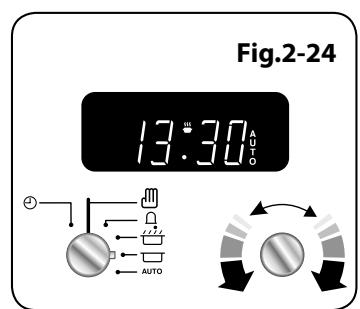
Turn the Timer knob to the () position. The display will show the current time of day plus the 'cook time' you just set. Use the Adjusting knob to set the 'stop time' required (Fig.2-24).
The 'stop time' is displayed, followed by 'AUTO'. Set the oven(s) to the cooking temperature you need. Turn the Timer knob to the 'AUTO' setting.
When your cooking is finished, the beeper sounds. Turn the Timer knob to the vertical (凹) to return to manual cooking.

English
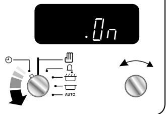
Fig.2-25
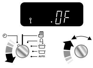
Fig.2-26
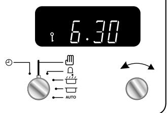
Fig.2-27
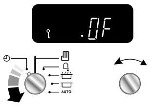
Fig.2-28
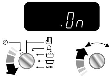
Fig.2-29
Fig.2-30
A - Top view, B - Side view, C - Shelf guard, D - Front The shelf guard should be at the back pointing upwards
Fig.2-31
A-Flat shelf, B-Drop shelf
If you are out, do not worry about the beeper going off – it will stop on its own after a while. When you return, turn the Timer knob to the vertical (凹) to return to manual cooking.
AUTO is showing, but you want to revert to manual cooking
You can cancel any automatic settings by briefly turning the Timer knob to the clock symbol (⊙) and then releasing it.
Key Lock
When the key lock is activated, the left-hand oven is locked and will not come on.
To activate the key lock
Make sure that the clock is in manual mode and cancel any active programs.
Turn and hold the Timer knob to the clock symbol (⊙) for about 8 seconds. 'On' appears on the display (Fig.2-25).
Keep holding the Timer knob turned to the clock symbol (⊙) and turn the Adjusting knob clockwise until the key symbol (♀) and 'OF' shows on the display (Fig.2-26). Let go of the knobs.
The left-hand oven is now locked. After a few seconds the display will revert to show the time of day and the key symbol (Fig.2-27).
To turn off the key lock
Turn and hold the Timer knob to the clock symbol (⊙) for about 8 seconds. 'OF' will appear on the display (Fig.2-28).
Keep holding the Timer knob turned to the clock symbol (⊙) and turn the Adjusting knob clockwise until the key symbol (♀) goes out on the display and 'On' shows (Fig.2-29). Let go of the knobs.
After a few seconds, the display reverts to showing the time of day.
The left-hand oven can now be used normally.
Accessories
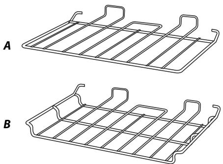
Oven Shelves – Left-hand (Main) Oven
In addition to the flat shelves (Fig.2-30), some models are supplied with a drop shelf (Fig.2-31). The drop shelf increases the possibilities for oven shelf spacing.
The oven shelves can be easily removed and refitted.
Pull the shelf forward until the back of the shelf is stopped by the shelf stop bumps in the oven sides (Fig.2-32).
Lift up the front of the shelf so the back of the shelf will pass under the shelf stop and then pull the shelf forward (Fig.2-33).
To refit the shelf, line up the shelf with a groove in the oven side and push the shelf back until the ends hit the shelf stop. Lift up the front so the shelf ends clear the shelf stops, and then lower the front so that the shelf is level and push it fully back (Fig.2-34).
Oven shelves – Right-hand (Tall) Oven
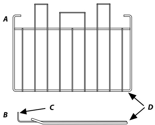
The tall oven is supplied with four flat cooking shelves (Fig.2-35), and a plate warming shelf (Fig.2-36).
When using the tall oven, you can cook on all four shelves at the same time, but make sure that they are well spaced out allow the hot air to circulate.
The Handyrack (Main Oven)
The Handyrack (Fig.2-37) fits to the left-hand oven door only. Food cooking on it is easy to attend to, because it is accessible when the door is open.
The maximum weight that can be held by the Handyrack is 5.5kg (12lb). It should only be used with the supplied roasting tin, which is designed to fit the Handyrack. Any other vessel could be unstable.
Additional roasting tins are available from our cookware collection - Part Code RM027.
It can be fitted at two different heights. One of the oven shelves must be removed and the other positioned to suit.
When the Handyrack is used in its highest position, other dishes can be cooked on the bottom shelf position or base of the oven.
When the Handyrack is used in its lowest position, other dishes can be cooked on the second shelf position or base of the oven.
To fit the Handyrack, locate one side of it on the door bracket (Fig.2-38).
Then spring the other side out to clip it onto the other bracket (Fig.2-39).
Main Oven Light
Press the button to turn the light on (Fig.2-40).
If the oven light fails, turn off the power supply before changing the bulb. See the 'Troubleshooting' section for details on how to change the bulb.
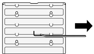
Fig.2-32
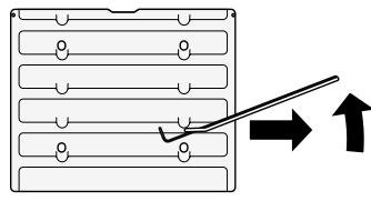
Fig.2-33
Fig.2-34
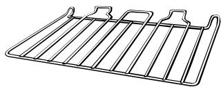
Fig.2-35

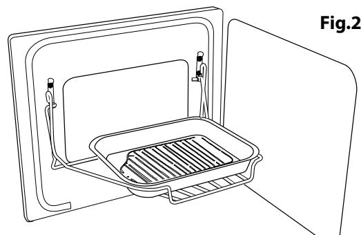
Fig.2-37
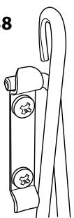
Fig.2-38
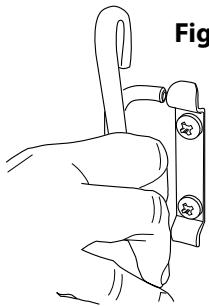
Fig.2-39

Fig.2-40
English
3. Cooking Tips
Tips on Cooking with the Timer
If you want to cook more than one dish, choose dishes that require approximately the same cooking time. However, dishes can be 'slowed down' slightly by using small containers and covering them with aluminium foil, or 'speeded up' slightly by cooking smaller quantities or placing them in larger containers.
Very perishable foods such as pork or fish should be avoided if a long delay period is planned, especially in hot weather.
DO NOT place warm food in the oven to be timed.
DO NOT use a timed oven that is already warm.
A DO NOT use the timed oven if the adjoining oven is already warm.
Whole poultry must be thoroughly defrosted before being placed in the oven. Check that meat and poultry are fully cooked before serving.
General Oven Tips
The wire shelves should always be pushed firmly to the back of the oven.
Baking trays with food cooking on them should be placed level with the front edge of the oven's wire shelves. Other containers should be placed centrally. Keep all trays and containers away from the back of the oven, as overbrowning of the food may occur.
For even browning, the maximum recommended size of a baking tray is 340mm ( 13 12'' ) by 340mm ( 13 12'' ) in the main oven and 232mm ( 9 18'' ) and 321mm ( 12 58'' ) in the tall oven.
When the oven is on, do not leave the door open for longer than necessary, otherwise the knobs may get very hot.
Always leave a 'fingers width' between dishes on the same shelf. This allows the heat to circulate freely around them.
To reduce fat splashing when you add vegetables to hot fat around a roast, dry them thoroughly or brush lightly with cooking oil.
Where dishes may boil and spill over during cooking, place them on a baking tray.
The Cook & Clean oven liners (see 'Cleaning Your Cooker') work better when fat splashes are avoided. Cover meat when cooking.
- Sufficient heat rises out of the oven while cooking to warm plates in the grill compartment.
If you want to brown the base of a pastry dish, preheat the baking tray for 15 minutes before placing the dish in the centre of the tray.
4. Cleaning Your Cooker
Isolate the electricity supply before carrying out any major cleaning. Allow the cooker to cool.
Never use paint solvents, washing soda, caustic cleaners, biological powders, bleach, chlorine based bleach cleaners, coarse abrasives or salt. Do not mix different cleaning products – they may react together with hazardous results.
All parts of the cooker can be cleaned with hot soapy water – but take care that no surplus water seeps into the appliance.
We have developed a range of cleaning products that give maximum performance without damaging the enamel and painted surfaces, in particular a Ceramic Hob Cleaner set with scraper. More information is available through either the Cookware Collection brochure supplied with your cooker or our website www.rangemastercookshop.co.uk.
Remember to switch the electricity supply back on and reset the clock before reusing the cooker.
Hob
Daily Care
First of all make sure that all heat indicator lights are off and that the cooking surface is cool. Apply a small dab of ceramic cleaning cream in the centre of each area to be cleaned. dampen a clean paper towel and work the cream onto the cooking surface. As a final step, wipe the cooking surface with a clean, dry paper towel.
Cleaning Spills
For spills and boil-overs that occur while cooking, turn the unit off and wipe the area surrounding the hot zone with a clean paper towel. If a spill (other than a sugary substance) is on the hot zone, do not clean until the unit has completely cooled down, and then follow the instructions below ('Cleaning burned-on spills').
If you accidentally melt anything on the surface, or if you spill foods with a high sugar content (preserves, tomato sauce, fruit juice, etc.), remove the spill IMMEDIATELY with a razor scraper, while the unit is still hot.
IMPORTANT: Use an oven glove to protect your hand from potential burns.
Scrape the major spill or melted material from the cooking zone and push into a cold area. Then, turn the unit 'OFF' and allow it to cool before cleaning further. After the cooking surface cools down and the heat indicator lights go off, follow the 'Daily Care' procedure outlined above.
Cleaning Burned-on Spills
Make sure that the heat indicator lights are off and that the hob is cool. Remove the excess burned-on substance with a single-edged razor scraper. Hold the scraper at an angle of about 30^ to the surface and then scrape off the burned-on matter (Fig.4-1).
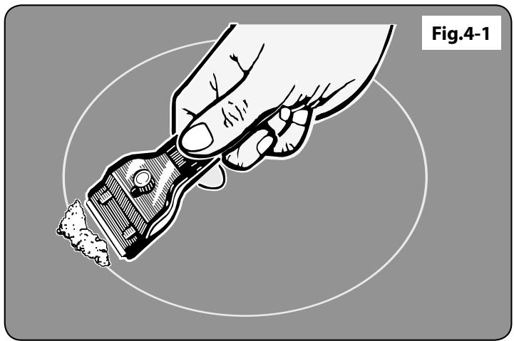
English
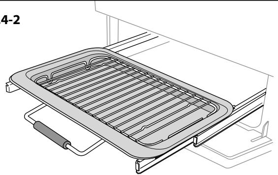
Fig.4-2
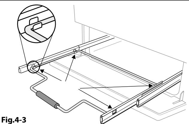
Fig.4-3
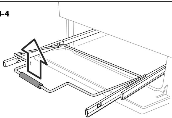
Fig.4-4
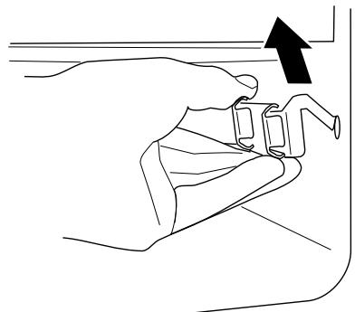
Fig.4-5
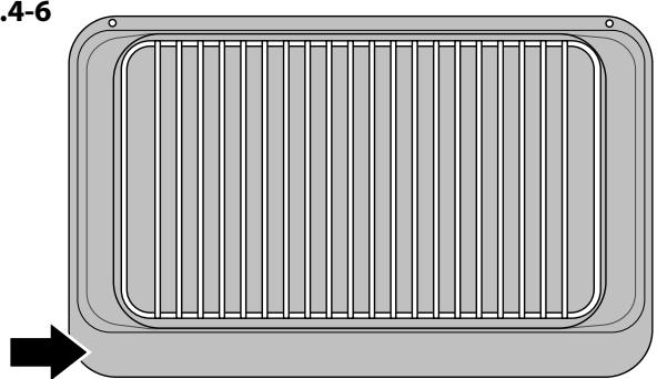
Fig.4-6
Once you have removed as much as possible with the scraper, follow the 'Daily Care' procedure outlined above.
Glide-out Grill
The grill pan and grid should be washed in hot soapy water. After grilling meats or any foods that soil, leave to soak for a few minutes immediately after use. Stubborn particles may be removed from the grid using a nylon brush. Alternatively, the grill pan can be washed in a dishwasher.

Before you remove any of the grill parts for cleaning, ensure that they are cool, or use oven gloves.
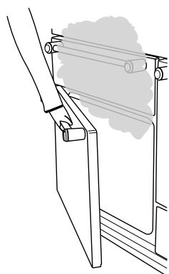
The grill pan can be easily removed for cleaning as follows. Remove the grill pan support frame by pulling the grill pan forward (Fig.4-2).
Lift the grill pan clear of the support frame. The support frame is held to the side rails by two clips on each side (Fig.4-3).
For each side, support the side rail with one hand and with the other hand lift the frame up and out of the side clips (Fig.4-4).
For safety, push the side rails back into the grill chamber.
If you need to remove the side rails to allow cleaning of the grill chamber, you can unhook them from the grill chamber sides (Fig.4-5) and wipe the sides clean with a soft cloth and mild detergent.

DO NOT use any abrasive substances.

DO NOT put the side runners in a dishwasher.
Once you have finished, hook the side rails back onto the sides of the chamber. To refit the frame, pull the side rails forward and, for each side in turn, support the side rail and press the frame down into the side rails. Replace the grill pan. When refitting the grill pan, ensure that the wide rim is at the front (Fig.4-6).
Control Panel and Doors
Avoid using any abrasive cleaners, including cream cleaners, on brushed stainless steel surfaces. For best results, use a liquid detergent or our Multi-purpose Cleaner.
The same cleaner can also be used on the doors. Alternatively, use a soft cloth wrung out in clean hot soapy water. You can use the same method for cleaning the control panel and knobs (although we do supply a specialist Fascia Cleaner). After cleaning, polish with a dry cloth.
Ovens
'Cook & Clean' Panels
The main oven has side 'Cook & Clean' panels which have been coated with a special enamel that partly cleans itself. This does not stop all marks on the lining, but helps to reduce the amount of manual cleaning needed.
These panels work better above 200^ C . If you do most of your cooking below this temperature, occasionally remove the panels and wipe with a lint free cloth and hot soapy water. The panels should then be dried and replaced and the oven
heated at 200^ for about one hour. This will ensure that the panels are working effectively.
Removing the Panels to clean the Enamel Interior
If you wish to clean the enamel interior of the oven, you will first need to remove the shelves.
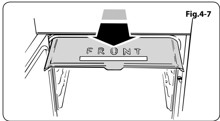
The right-hand oven has a removable oven roof. Slide the roof liner forwards and remove (Fig.4-7).
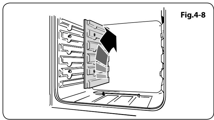
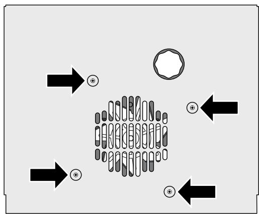
Each side of the oven is fixed with four fixing screws. You do not have to remove the screws to remove the oven panels. Simply lift each side panel upwards, slide them off the screws and then pull them forwards (Fig.4-8).
Once the panels have been removed, the oven enamel interior can be cleaned.

DO NOT use steel wool, oven cleaning pads, or any other materials that will scratch the surface.
The Tall Oven
To clean the oven sides, slide out the shelves, unhook the supports from the oven sides and lift out (Fig.4-9).

English
5. Troubleshooting

Interference with and repairs to the hob MUST NOT be carried out by unqualified persons. Do not try to repair the hob as this may result in injury and damage to the hob. Please arrange for repair by a suitably competent person.
Note: The induction hob is able to self-diagnose a number of problems and can show this information to the user via the hob control display. Error codes may be displayed if your hob has developed a fault.
If you appliance reports an error or is not working, you may be able to correct the fault by consulting the following.
Error code E2 is displayed
The electronic unit is too hot. Please check the installation of the cooker, making sure that there is sufficient ventilation. In extreme cases, if a cooking utensil has been allowed to boil dry this error code may also be displayed. If in doubt please contact your installer or a qualified repair engineer.
No display operation
Over voltage or loss of supply voltage to the cooker. If in doubt please contact your installer or a qualified repair engineer.
Error code ERxx or Ex is displayed
The appliance has developed an internal technical fault that cannot be rectified by the user. Please contact your installer or a qualified repair engineer.
The fuse blows or the RCD trips regularly
Please contact your installer or a qualified repair engineer.
The hob will not switch on
Has the wiring system in the house blown a fuse or tripped an RCD?
Has the hob been correctly connected to the mains supply?
Has the child lock been activated? Please refer to the child lock section for details of this function.
The induction hob is noisy
When using the induction hob there may be some 'noise' emitted from the pan. This is normal and may be most noticeable when cooking on high power settings or if 5 pans are used simultaneously. The type of pan may also contribute to induction 'noise'.
The cooling fan
The induction hob incorporates a cooling fan. This cooling fan is active when either the grill or ovens are on. Under certain conditions, the cooling fan may remain active when the grill or ovens are switched off. This is normal and the fan will switch off automatically.
A crack has appeared in the hob surface
Disconnect the cooker immediately from the power supply and arrange for its repair. Do not use the cooker until after the repair.
My hob is scratched
Always use the cleaning methods recommended in this guide, and ensure that the pan bottoms are smooth and clean.
Marks from mineral deposits from water or food can be removed with a cleaning cream. However, tiny scratches are not removable but will become less visible in time as a result of cleaning.
The oven fan is noisy
The note of the oven fan may change as the oven heats up – this is perfectly normal.
Grill not cooking properly
Are you using the pan and trivet supplied with the cooker? Is the pan being used on the runners, not the floor of the compartment? Is the grill tray pushed back fully to the 'back stop' position?
The knobs get hot when I use the oven or grill. Can I avoid this?
Yes, this is caused by heat rising from the oven or the grill, and heating them up. Do not leave the oven door open. Make sure that the grill pan is pushed right back to the 'back stop' when grilling.
Always grill with the grill compartment door open.
If there is an installation problem and I don't get my original installer to come back to fix it, who pays?
You do. Service organisations will charge for their callouts if they are correcting work carried out by your original installer. Therefore, it's in your own interest to keep track of this installer so that you can contact them as required.
Power failure
In the event of a failure in the electrical supply, remember to reset the clock to ensure that the timed oven continues to operate.
Food is cooking too slowly, too quickly, or burning
Cooking times may differ from your previous oven. Adjust the settings according to your own individual tastes.
The oven is not cooking evenly
Do not use a baking tray with dimensions larger than those specified in the section on 'General Oven Tips'.
If you are cooking a large item, be prepared to turn it round during cooking.
If two shelves are used, check that space has been left for the heat to circulate. When a baking tray is put into the oven, ensure that it is placed centrally on the shelf.
Check that the door seal is not damaged and that the door catch is adjusted so that the door is held firmly against the seal.
A dish of water when placed on the shelf should be the same depth all over. (For example, if it is deeper at the back, then the back of the cooker should be raised up or the front lowered.) If the cooker is not level, arrange for your supplier to level it for you.
The timed oven is not coming on when turned on manually
Is the power on? Is the clock illuminated? If not, there may be something wrong with the power supply. Is the cooker supply on at the isolator switch?
Has the time of day been set?
Is the key symbol (?) showing in the display to signify that the oven is locked? See the 'Clock' section of the instructions for more information on the key lock feature.
The timed oven is not coming on when automatic cooking
Has the oven knob been left in the OFF position by mistake? Is the oven locked (see above)?
Oven temperature getting hotter as the cooker gets older
If turning the temperature down using the oven control knob has not worked, or has only worked for a short time, then you may need a new thermostat. This should be fitted by a service person.
The Oven light is not working
The bulb has probably blown. You can buy a replacement bulb (which is not covered under the guarantee) from most electrical stores. Ask for an Edison screw fitting 15W 240V lamp, FOR OVENS. It must be a special bulb, heat resistant to 300^ . See the HELP leaflet for spares by mail order.
Before removing the existing bulb, turn off the power supply and ensure that the oven is cool. Open the oven door and remove the oven shelves.
Locate the bulb cover and unscrew it by turning it anticlockwise (it may be very stiff).
Now unscrew the existing bulb anticlockwise, taking care to protect your fingers with a glove in case the bulb should shatter.
Screw in the new bulb clockwise and then screw the bulb cover back on. Turn on the electricity supply and check that the bulb now lights.
INSTALLATION
Check the appliance is electrically safe when you have finished.
6. Installation
Dear Installer
Before you start your installation, please complete the details below, so that, if your customer has a problem relating to your installation, they will be able to contact you easily.
| Installer's Name |
| Installer's Company |
| Installer's Telephone number |
| Appliance Serial Number |
Safety Requirements
The cooker must be installed in a well-ventilated space, in accordance with the section entitled 'Electrical Connection'.
Read these instructions before installing or using the appliance.
Provision of Ventilation
This appliance is not connected to a combustion products evacuation device. Therefore, particular attention must be given to the relevant requirements regarding ventilation.
All rooms require a window that can be opened, or equivalent, while some rooms require a permanent vent in addition to the window.
Location of Cooker
The cooker may be installed in a kitchen/kitchen diner but NOT in a room containing a bath or shower.
This appliance is designed for domestic cooking only. Use for any other purpose could invalidate any warranty or liability claim.
You will need the following equipment to complete the cooker installation satisfactorily:
Multimeter (for electrical checks)
Cooker levelling tool with Allen keys (provided in pack)
You will also need the following tools:
- Electric drill
- Masonry drill bit (only required if fitting the cooker on a stone or concrete floor)
- Wall plugs (only required if fitting the cooker on a stone or concrete floor)
- Steel tape measure
- Cross-head screwdriver
- Flat-bladed screwdriver
- Spirit level
- Pencil
- Adjustable spanner
Checking the parts:
| Levelling tool and Allen keys | Grill pan and trivet |
| 1 flat oven shelf and 1 drop shelf | Handyrack |
| Roasting tin | Plinth |
| Tall oven shelves and shelf supports | Splashback |
INSTALLATION
Check the appliance is electrically safe when you have finished.
Positioning the Cooker
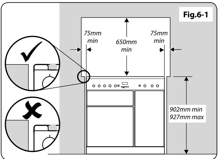
Fig.6-1 shows the minimum recommended distance from the cooker to nearby surfaces.
The cooker should not be placed on a base.
The hotplate surround should be level with, or above, any adjacent work surface. A gap of 75mm should be left between each side of the cooker ABOVE the hotplate level and any adjacent vertical surface.
For non-combustible surfaces (such as unpainted metal or ceramic tiles), this can be reduced to 25mm . A minimum space of 650mm is required between the top of the hob and a horizontal combustible surface.
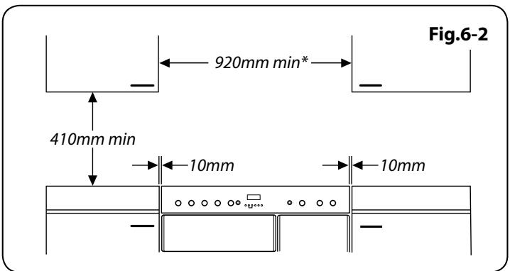
Fig.6-2 shows the suggested clearances above the cooker.
*Any cooker hood should be installed in accordance with the hood manufacturer's instructions.
Surfaces of furniture and walls at the sides and rear of the appliance should be heat, splash and steam resistant. Certain types of vinyl or laminate kitchen furniture are particularly prone to heat damage and discolouration. We cannot accept responsibility for damage caused by normal use of the cooker to any material that de-laminates or discolours at temperatures less than 65^ above room temperature.
We recommend a gap of 920mm between units to allow for moving the cooker. Do not box the cooker in – it must be possible to move the cooker in and out for cleaning and servicing.
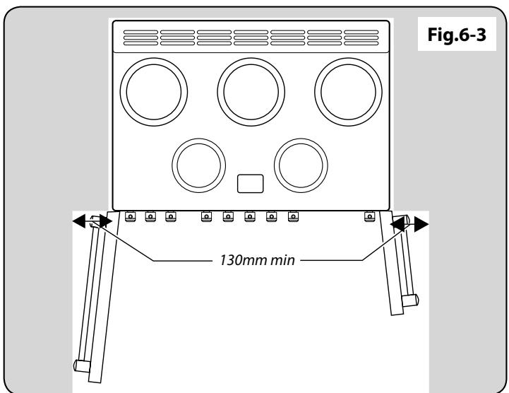
A clearance of 130mm is required if the cooker is near a corner of the kitchen, to allow the oven doors to open (Fig.6-3). The actual opening of the doors is slightly less, but this allows for some protection of your hand as you open the door.
Unpacking the Cooker
Do not take any packaging off the cooker until it is directly in front of the place in which it is to be installed (unless it will not fit through a door in its outer packaging).
Cut the banding straps and lift the cardboard box off the cooker, leaving the cooker standing on the base packaging. See the loose unpacking sheet.
Moving the Cooker

On no account try and move the cooker while it is plugged into the electricity supply.

The cooker is very heavy, so take great care.
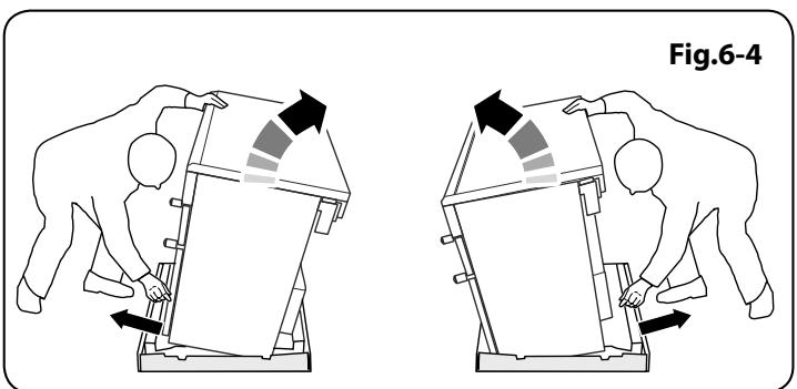
We recommend two people manoeuvre the cooker. Ensure that the floor covering is firmly fixed, or removed to prevent it being disturbed when moving the cooker around. To help you, there are two levelling rollers at the back and two screw-down levelling feet at the front. You will need the levelling tool.
From the back, tilt the cooker forward and remove the rear half of the polystyrene base pack (Fig.6-4). Repeat from the front and remove the front half of the poly base.
INSTALLATION
Check the appliance is electrically safe when you have finished.
Lower the Two Rear Rollers
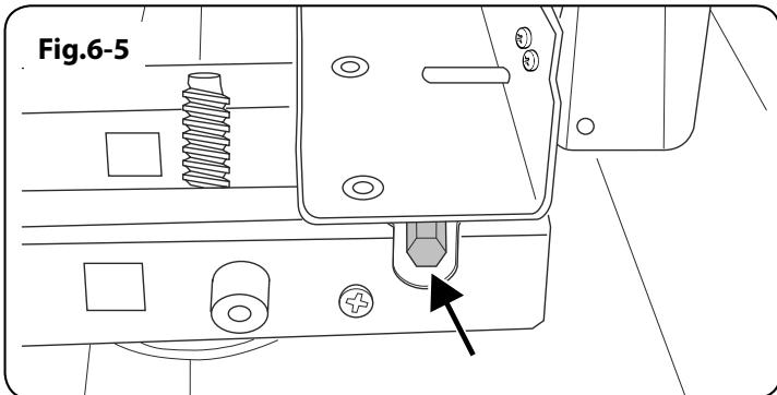
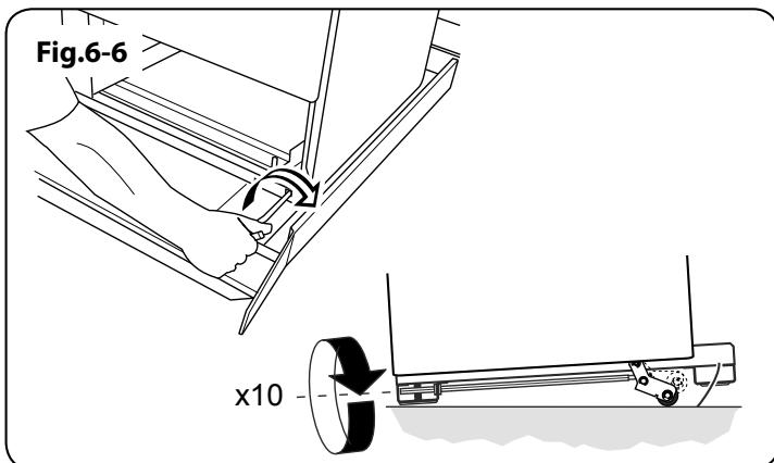
First fit the levelling tool on the hexagonal adjusting nut (Fig.6-5).
Make 10 complete (360^) turns clockwise (Fig.6-6). (This means turning and removing the levelling tool 20 times.)
Make sure you lower BOTH REAR ROLLERS. There are two adjusting nuts, one for each roller, at both the front and bottom corners of the cooker.
Completing the Move
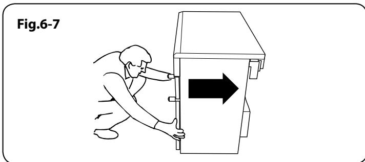
Unfold the rear edge of the pack base tray. Open the grill door and right-hand oven door so that you can get a good grip on the bottom of the fascia panel as you move the cooker.
Grip under the fascia panel and lift the front of the cooker slightly (Fig.6-7).
Carefully push the cooker backwards off the pack base. Remove the pack base tray. Position the cooker close to its final position, leaving just enough space to get behind it.
DO NOT use the door handles or control knobs to manoeuvre the cooker.
Repositioning the Cooker following Connection
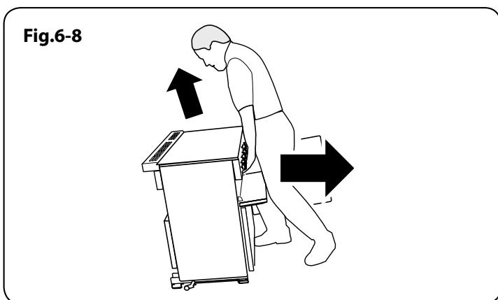
If you need to move the cooker once it has been connected, make sure it is switched off at the supply switch before gripping under the fascia panel and lifting the front of the cooker slightly (Fig.6-8). Check behind the cooker to ensure that the electricity cable is not caught. As you progress, always ensure that the cable has sufficient slack to allow the cooker to move.
If a stability chain is fitted, release it as you ease the cooker out. Do not forget to refit it when you replace the cooker.
When you replace the cooker, check behind it again once more to ensure that the electricity cable is not caught or trapped.
Levelling
It is recommended that you use a spirit level on a shelf in one of the ovens to check for level.
Place the cooker in its intended position. Take care not to twist it within the gap between the kitchen units, as otherwise, damage may occur to the cooker or units.
The front feet and rear rollers can be adjusted to level the cooker. To adjust the height of the rear of the cooker, use the levelling tool supplied to turn the roller adjusting nuts at the front bottom corners of the cooker. To raise or lower the feet, simply turn the disks that are fitted onto them.
Fitting the Handles
To fit the handles, first remove the 4mm Allen screws from the doors. Locate the door handles to the doors, making sure that the handles are above the fittings, and secure in position
INSTALLATION
Check the appliance is electrically safe when you have finished.
using the Allen screws. Insert the blanking plugs into the fixing holes.
The fit the front handrail, first remove the 4mm Allen screws from the top corners of the fascia. Locate the handrail to the fascia and secure in place.
Fitting the Splashback (optional)
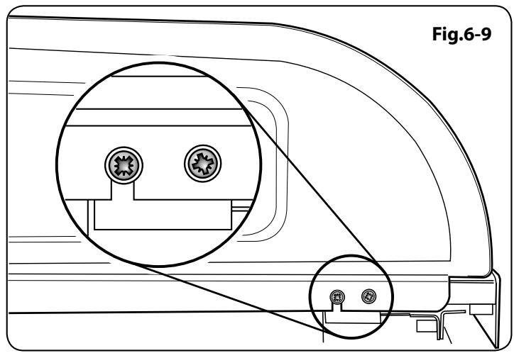
The splashback fits the back of the cooker. It is secured using 4 screws (2 at each end) in the rear edge of the flue grille.
Remove the outer 2 screws and then loosen the inner pair. Fit the splashback over the inner screws and then refit the outer screws (Fig.6-9). Tighten all screws to secure.
Electrical Connection
The cooker must be installed by a qualified electrician, in accordance with all relevant British Standards/Codes of Practice (in particular BS 7671), or with the relevant national and local regulations.
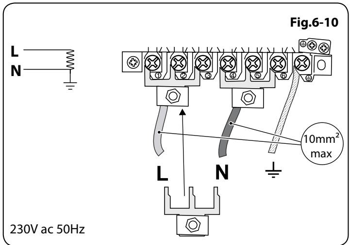
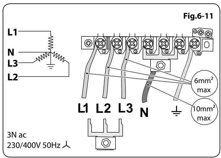
WARNING: THE APPLIANCE MUST BE EARTHED.
Note: The cooker must be connected to the correct electrical supply as stated on the voltage label on the cooker, through a suitable cooker control unit incorporating a double pole switch, having a contact separation of at least 3mm in all poles.
A The cooker must not be connected to an ordinary domestic power point.
Access to the mains terminal is gained by removing the electrical terminal cover box on the back panel. Connect the mains cable to the correct terminals for your electrical supply type (Fig.6-10 and Fig.6-11). Check that the links are correctly fitted and that the terminal screws are tight. Secure the mains cable using the cable clamp.
Hob Check
Check each cooking zone in turn. Be sure to use pans of the correct size and material.
Grill Check
Turn on the grill control and check that the grill heats up.
Oven Check
Set the clock as described earlier, and then turn on the ovens. Check the oven fans start to turn and that the ovens heat up.
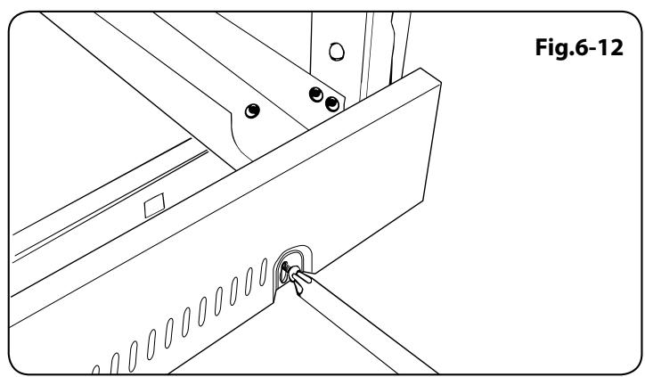
Fitting the Plinth
Loosen the three screws along the front bottom edge of the cooker. Hook the central keyhole over the central screw. Twist and fit each end keyhole over their respective screws. Tighten the fixing screws (Fig.6-12).
Please complete your contact details in the front of this section. Please inform the user how to operate the cooker and hand over the instruction pack.
Thank you.
7. Servicing

Disconnect the cooker from the electricity supply before servicing, particularly before removing any of the following: control panel, side panels, ceramic hob, or any of the electrical components or cover boxes.

Before reconnection, check that the appliance is electrically safe.
1. To Remove a Side Panel
Disconnect from electricity supply.
Pull the cooker forward. Remove the fixing screws.
Remove the retaining screws for each panel (one at the front, two at the rear, and one at each lower front corner of the side panels).
Reassemble in reverse order.
2. To Lift up the Ceramic Hob
Disconnect from electricity supply.
Remove the blanking plugs at the top front of each of the side panels to allow access to the hob fixing screws (1 each side) at the top of the side uprights. Remove these screws.
Lift up the ceramic hob at the front and prop in position with a non-metallic prop.
CAUTION: The ceramic hob material is much more sensitive to scratches on the underside than the top.
Take care not to touch or scratch the underside of the ceramic as this will weaken the material and cause the top to shatter.
3. To Remove the Control Panel
Disconnect from electricity supply.
Remove the two blanking plugs from the handrail fixing brackets. Remove the handrail by unscrewing the 2 end bracket fixing screws (Fig.7-1).
Pull off all the control knobs. Open the grill and right-hand oven door and remove the control panel fixing screws underneath the control panel. The screws directly below the clock are for the clock fixing bracket, so do not remove them at this stage.
Lift the control panel, pull forward and disconnect the wiring from the rear.
Reassemble in reverse order. When replacing leads, refer to the wiring diagram in this manual. Check the operation of the timer.
4. To Replace a Hob Element
Disconnect from electricity supply.
Lift up the ceramic hob (see 2). The Induction Heating Elements (IHE) are now accessible. Note the wire connection positions and element orientation for re-assembly. Disconnect the wires, and remove the element unit and springs. Re-assemble in the reverse order.
Note: The IHE will require commissioning when the hob has been refitted.
5. To Replace the Light Switch
Disconnect from electricity supply.
Remove the control panel (see 1).
Note: The old switch may be destroyed during removal.
Remove the old switch from its bezel by gripping the switch body behind the control panel and twisting sharply. Remove the switch bezel by folding back its locking wings and pushing forward. Fit the new bezel to the control panel by first lining up the raised key on its body with the cut-out in the control panel and pushing it in from the front.
Assemble the new switch to the bezel by lining up the key sections and pushing home. Fit the new button by pushing in from the front.
Replace the Control Panel in reverse order and test for correct operation.
6. To Remove the Electronic Timer
Disconnect from electricity supply.
Remove the control panel (see 1). Pull off the timer control button(s).
Remove the timer/mounting bracket assembly from the control panel by removing the fixing screws.
Remove the timer from its mounting bracket by depressing the plastic lugs on the timer case, at the same time pulling the unit forward.
Reassemble in reverse order. When replacing the leads, refer to the wiring diagram in this manual. Check the operation of the timer.
7. To Replace a Thermostat
Disconnect from the electricity supply.
Remove control panel (see 1) and lift hob (see 3). Open the oven door. Remove the oven furniture and slide out the oven roof liner if fitted.
For the right-hand oven, remove the thermostat phial cover (two screws). Unclip the thermostat phial from the clips in the oven back.
For the left-hand oven, pull cooker forward to gain access to the cover box at the rear of the cooker. Remove the four screws securing the cover and lift clear.
Feed the thermostat capillary out of the oven. Disconnect the wiring from the thermostat. Remove two screws holding thermostat to mounting panel. Fit new thermostat and reassemble in reverse order. Ensure that the phial is clipped to the oven back with the phial centrally positioned between the clips.
Check the operation of the thermostat.
8. To Replace the Grill Controller
Disconnect from electricity supply.
Remove the control panel and lift up the hob (see 1 and 3). Disconnect the wiring from the controller. Remove the two screws holding the controller to the mounting panel. Fit the new controller and reassemble in reverse order. Check for correct operation.
9. To Remove the Grill Door
Remove the control panel (see 1). Remove the left-hand side panel (see 2). Remove the centre cover strip (5 screws, 2 top, 2 bottom, 1 in middle). Remove the two countersunk screws (1 each side) securing the grill hinge arms to the front of the grill chamber.
Note: The arms are spring tensioned. Carefully remove the grill door. Retain the gaskets.
Reassemble in reverse order ensuring that the gasket is fitted between the hinge arm and the front of the grill chamber.
10. To Remove Grill Element
Disconnect from electricity supply.
Remove grill pan from inside the grill compartment; remove the enamelled front shield from the grill roof, by undoing the two screws and washers.
Remove the two screws and washers securing the grill element front support. Remove the screws from the grill element.
Lift the element out carefully, disconnecting the leads from the element terminals (noting their position). If it is not possible to disconnect the leads in this way, pull the cooker forward to gain access to the rear, remove the screws securing the electric cover to the back sheet, remove the cover and disconnect the terminals from the rear.
Fit the new element and reassemble in reverse order. Check the operation of the grill.
11. To Replace an Oven Door
Open the oven door. Support the door and remove the two screws securing the upper hinge and gasket to the cooker front (Fig.7-2). Remove the door from the lower hinge by lifting slightly and moving outwards (Fig.7-3).

The door is heavy, so take care.
Reassemble in reverse order.
12. To Adjust an Oven Door Angle
The bottom hinge of either oven door can be adjusted to alter the angle of the door (Fig.7-4). Loosen the bottom hinge fixing screws and use the notch and a flat bladed screwdriver to move the position of the hinge to set the hinge position (Fig.7-5).
Retighten the hinge screws.
13. To Replace an Oven Door Outer Panel
Move the cooker forward to gain access to the sides.
Open the oven door slightly and remove the front panel fixing screws from the door sides – two each side (Fig.7-6).
Carefully lift off the outer door panel.
Remove the two plastic blanking plugs from the door handle. Remove the door handle from the panel by unscrewing the two retaining nuts. Fit the door handle to the new panel and refit the two blanking plugs to the fixing holes.
Note: If replacing the outer panel on the right-hand door (with the Thermodial), take care to make sure the sensor of the Thermodial is sealed to the door by the rubber grommet (Fig.7-7).
Fit the panel to the door. Reassemble in reverse order.
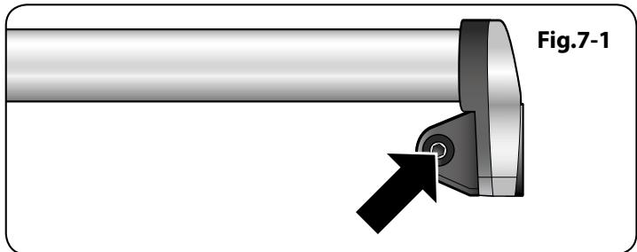
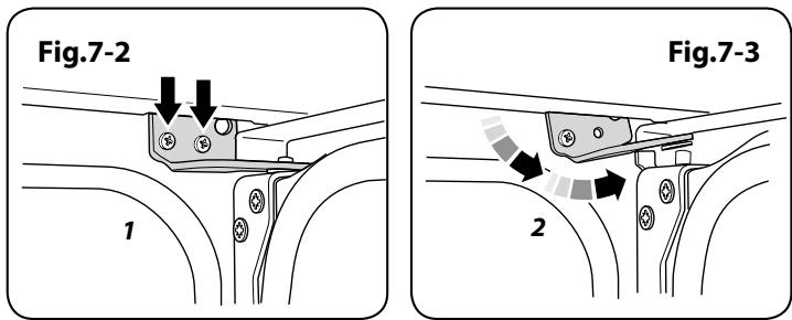
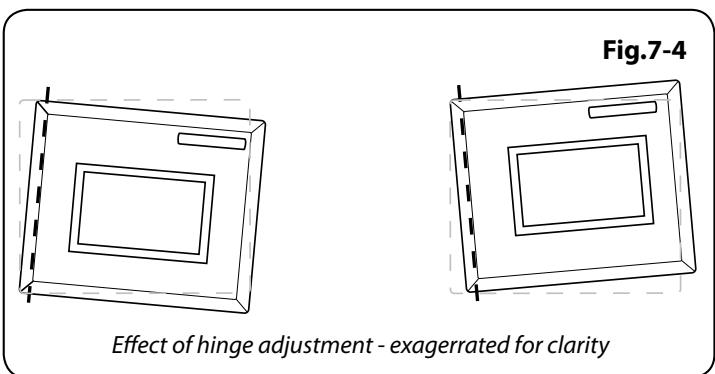
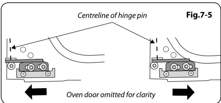
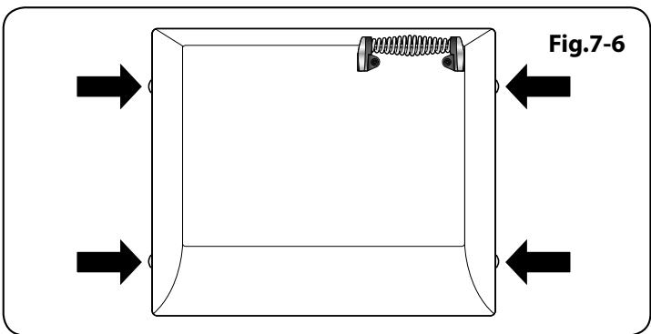
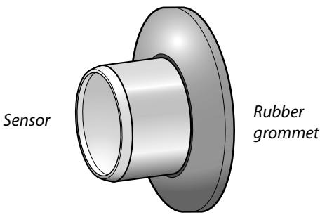
Fig.7-7
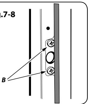
Fig.7-8
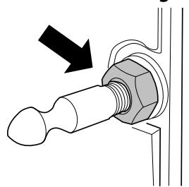
Fig.7-9
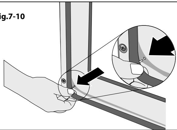
Fig.7-10
Fig.7-11
14. To Replace the Tall Oven Door Outer Panel
Remove the oven door (see 11). Lay the door face down on a suitable surface and remove the two screws from the bottom edge of the door and the two screws from the inside face of the door.
Remove the outer door panel. Remove the handle by unscrewing the two screws.
Unscrew the two cross-headed screws holding the door handle fixing bracket to the door panel. Fit the door handle bracket and door handle to the new panel.
Fit the panel to the door and reassemble in the reverse order.
15. To Change the Main Oven Door Latch
Remove the outer door panel (see 13). Remove screws 'B' that hold the latch assembly to the inner door panel (Fig.7-8). Fit the new catch and reassemble in reverse order.
Verify the door operation.
16. To Adjust the Main Oven Door Catch Keep
Open the oven door, and slacken off the locknut at the base of the keep (Fig.7-9). Screw in or out as required until the required fit is obtained. Retighten the locking nut.
17. To Replace the Tall oven Magnetic Latch
Remove the control panel (see 1). Remove the plinth (3 screws) and the central vertical cover (5 screws). Prise the retaining clip off the magnet unit.
Fit the new unit and retaining clip, and reassemble in reverse order. Check that the door operates correctly.
18. To Replace an Oven Door Seal
Open the oven door. The seal has small hooks that hold it in place by locating into holes in the rear door face on the main oven and oven front face on tall oven. At the corner, pull the seal diagonally away from the door centre until the hook is released (Fig.7-10). Proceed to the next hook and release it in a similar way, and so on.
You can use force if the hooks are stiff, as the old seal will be discarded.
Carefully lift away the inner back. Reassemble in reverse order making sure that the four screws and washers are fully tightened.
19. To Remove an Oven Element Thermal Cut-out
Disconnect from electricity supply.
Pull the cooker forward to gain access to the cover box. Undo the cover screws and lift clear. The cut-out is located on the earth plate beside the oven element connections. Disconnect the cut-out wiring. Undo the fixings that secure the cut-out to the earth plate and remove. Fit the replacement control and re-assemble in reverse order.
20. To Remove an Oven Inner Back
Disconnect from electricity supply.
Open the door and remove the shelves. Remove the screws and washers securing the inner back to the back of the oven (Fig.7-11). Carefully lift away the inner back. Reassemble in reverse order making sure that the screws and washers are fully tightened.
21. To Remove the Fan Oven Element
Disconnect from electricity supply.
Remove the oven inner back (see 20). Remove the two screws from the top of the element and the one from the bottom of the element inside the oven (Fig.7-12).
Lift the element out carefully, disconnecting the terminals connected to the element (noting their positions).
If it is not possible to disconnect the leads in this way, pull the cooker forward to gain access to the rear.
Remove the screws securing the electric cover to the back sheet, remove the cover and disconnect the terminals from the rear.
22. To Replace an Oven Fan
Disconnect from electricity supply.
Pull the cooker forward to gain access to the rear. Remove the screws securing the electric cover to the back sheet and remove the cover.
Disconnect the three terminals connected to the fan noting their position. Remove the oven inner back (see 20). Hold the fan blade and remove the centre nut (left-hand thread) two brass washers, fan blade and circlip. Unscrew the fan retaining nuts and washers (three off each) and lift the fan away from the rear of the cooker. Fit the new fan and reassemble in reverse order. Check the operation of the oven.
23. To Remove the Left-hand Oven Bottom and Top Elements
Disconnect from the electricity supply.
Bottom Element
Pull the cooker forward to access the cover boxes at the rear of the unit. Remove the fixings that secure the cover and lift it clear.
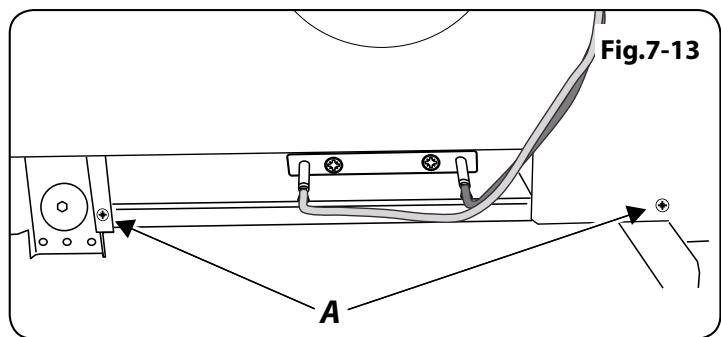
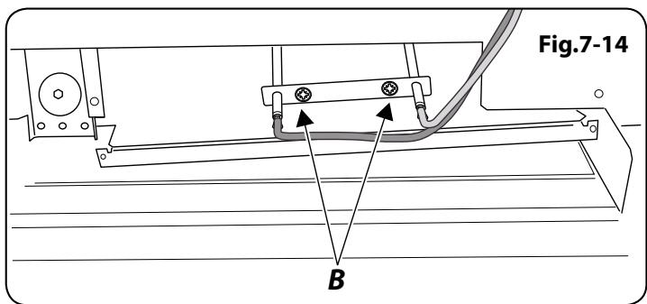
Remove the two screws 'A' and allow the plate to drop down (Fig.7-13). Remove the two screws 'B' holding the element to the bottom sheet (Fig.7-14). Undo the terminal connections, noting their positions. Withdraw the element.
Replace the element and re-assemble parts in reverse order.
Top Element
Open the left-hand oven door and undo the fixings that secure the heat shield. Remove the top element bracket fixings and withdraw the element.
Replace the element and re-assemble parts in reverse order. Check that the oven operates satisfactorily.
24. To Change Oven Light Bulb
Disconnect from electricity supply.
Make sure the oven is cool. Open the oven door and remove the oven shelves. Remove the grill pan and support from the grill chamber.
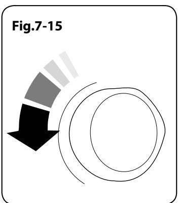
Unscrew the bulb cover by turning anticlockwise. It may be very stiff (Fig.7-15). Taking care to protect your fingers in case the bulb should shatter, unscrew the old bulb.
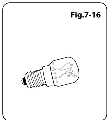
Fit an Edison screw fitting 15W 240V lamp, FOR OVENS. It must be a special bulb, heat resistant to 300^ (Fig.7-16).
Screw in the new bulb, and then screw back the bulb cover. Turn on the electricity supply and check that the bulb now lights.
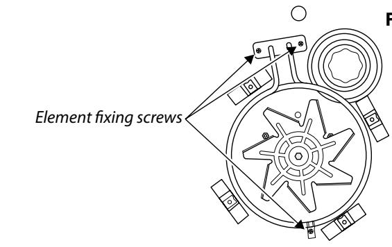
Fig.7-12
8. Circuit Diagram: Oven
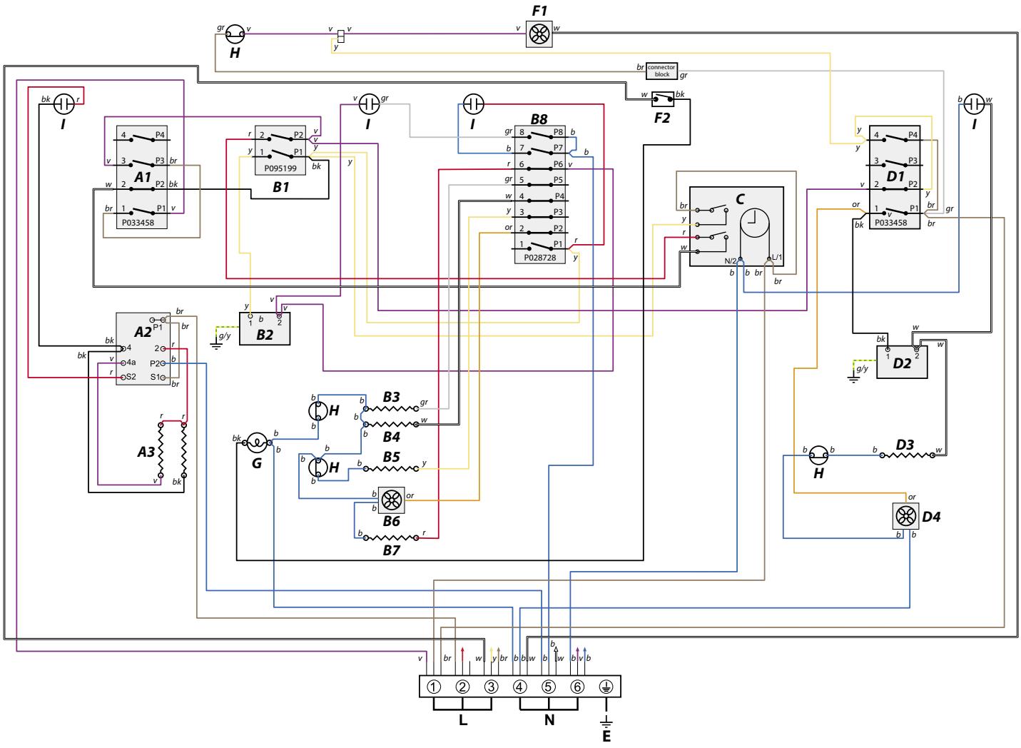
The connections shown in the circuit diagram are for single-phase. The ratings are for 230V 50Hz.
Key
| Code | Description |
| A1 | Grill front switch |
| A2 | Grill energy regulator |
| A3 | Grill elements |
| B1 | Left-hand oven front switch |
| B2 | Left-hand oven thermostat |
| B3 | Left-hand oven top element (outer) |
| B4 | Left-hand oven top element (inner) |
| B5 | Left-hand oven centre element |
| B6 | Left-hand oven fan |
| B7 | Left-hand oven base element |
| B8 | Left-hand multi-function switch |
| Code | Description |
| C | Clock |
| D1 | Right-hand oven front switch |
| D2 | Right-hand oven thermostat |
| D3 | Right-hand oven element |
| D4 | Right-hand oven fan |
| F1 | Cooling fan |
| F2 | Light switch |
| G | Oven light |
| H | Thermal cut-out |
| I | Neon |
| Colour Code | |
| b | Blue |
| br | Brown |
| bk | Black |
| or | Orange |
| r | Red |
| v | Violet |
| w | White |
| y | Yellow |
| g/y | Green/yellow |
| gr | Grey |
Circuit Diagram: Hob
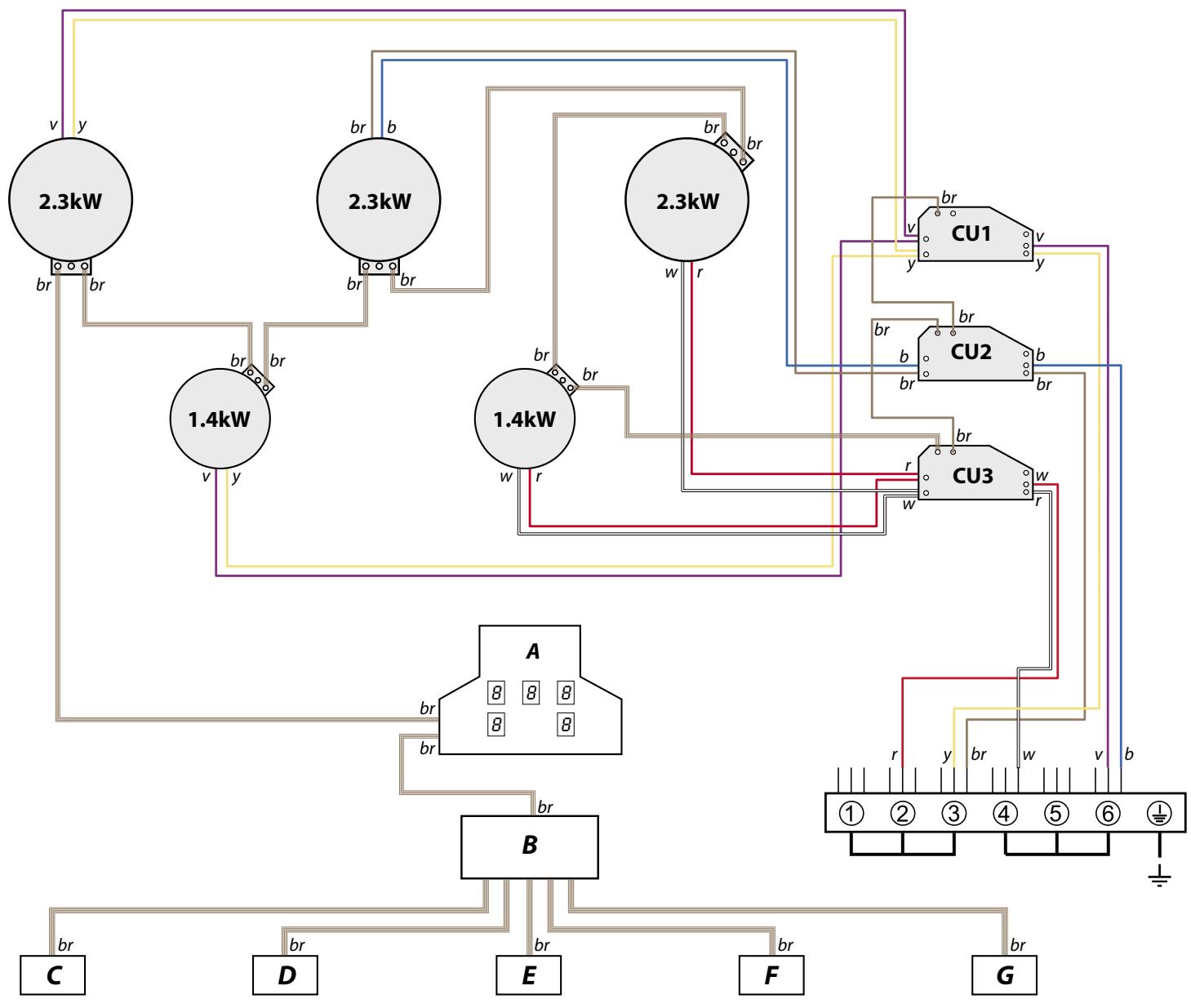
| Code | Description |
| A | Touchlite panel |
| B | Distribution board |
| C | Left-hand front control |
| D | Left-hand rear control |
| E | Central control |
| F | Right-hand rear control |
| G | Right-hand front control |
| CU1 | Left-hand pair (slave) control unit |
| CU2 | Centre (slave) control unit |
| CU3 | Right-hand pair (master) control unit |
| Colour Code | |
| b | Blue |
| br | Brown |
| bk | Black |
| or | Orange |
| r | Red |
| v | Violet |
| w | White |
| y | Yellow |
| g/y | Green/yellow |
| gr | Grey |
English
9. Technical Data
INSTALLER: Please leave these instructions with the User.
DATA BADGE LOCATION : Cooker back, serial number repeater badge below oven door opening.
Connections
| Electric | 220 - 240V 50Hz |
Dimensions
| Overall height | minimum 902mm | maximum 927mm |
| Overall width | 900mm | |
| Overall depth | 650mm | |
Refer to 'Positioning the Cooker'.
Ratings
| Output/Oven | Left-hand multi-function | Right-hand fan |
| Maximum output | 3.7kW | 2.5kW |
| Ovens | Main oven | Tall oven |
| Multi-function | Forced air convection | |
| Energy efficiency class on a scale of A (more efficient) to G (less efficient) | B | B |
| Energy consumption based on standard load | 0.90kWh | 0.99kWh |
| Usable volume (litres) | 62 | 53 |
| Size | Medium | Medium |
| Time to cook standard load | 41 minutes | 49 minutes |
| Surface area of the grid | 1400cm² | 790cm² |
| Grill | 2.3kW |
Maximum total electrical load at 230V 18.2kW (approximate total including oven lights, oven fan, etc.)
Contents
Gril Coulissant "Glide-out"
Clarence Street, Royal Leamington Spa,
Warwickshire, CV31 2AD, England.
Tel: +44 (0) 1926 457400 Fax: +44 (0) 1926 450526
E-mail: consumers @rangemaster.co.uk