
AHB91IX - Kitchen hood AIRLUX - Free user manual and instructions
Find the device manual for free AHB91IX AIRLUX in PDF.
| Product type | Range hood |
| Brand | AIRLUX |
| Model | AHB91IX |
| Width | 90 cm |
| Minimum safety distance (cooking surface) | 650 mm |
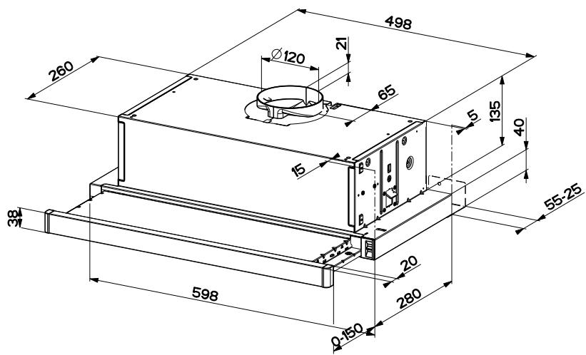
| Recommended exhaust diameter | 120 mm minimum |
| Power supply | 230 V ~ 50 Hz (check rating label) |
| Appliance class | I (grounding mandatory) |
| Number of speeds | 3 |
| Lighting | LED (replacement by after-sales service) |
| Grease filter | Dishwasher safe, clean every 2 months |
| Activated carbon filter | Not washable, replace every 4 months |
| Functions | Mechanical control (Lights, Motor, Speeds) |
| Use | Domestic |
| Standards | Compliant with local exhaust regulations |
| Weight | Approximately 15 kg (estimate) |
| Material | Stainless steel (finish) |
| Maintenance | Damp cloth and mild detergent |
Frequently Asked Questions - AHB91IX AIRLUX
User questions about AHB91IX AIRLUX
0 question about this device. Answer the ones you know or ask your own.
Ask a new question about this device
Download the instructions for your Kitchen hood in PDF format for free! Find your manual AHB91IX - AIRLUX and take your electronic device back in hand. On this page are published all the documents necessary for the use of your device. AHB91IX by AIRLUX.
USER MANUAL AHB91IX AIRLUX
IT LIBRETTO DI USO....3
EN USER MANUAL....7
FR MANUEL D'UTILISATION....10
PT LIVRO DE INSTRUÇÕES PARA UTILIZAÇÃO ....14
natural_image
Illustration of a hand holding a small object over a screen labeled 'Z' (no text or symbols on the diagram itself)For your safety and correct operation of the appliance, read this manual carefully before installation and use. Always keep these instructions with the appliance even if you move or sell it. Users must fully know the operation and safety features of the appliance.

The wire connection has to be done by specialized technician.
- The manufacturer will not be held liable for any damages resulting from incorrect or improper installation.
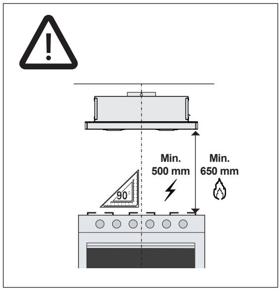
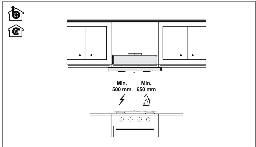
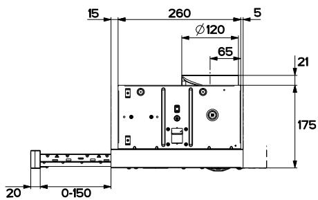
- The minimum safety distance between the cooker top and the extractor hood is 650 mm (some models can be installed at a lower height, please refer to the paragraphs on working dimensions and installation).
- If the instructions for installation for the gas hob specify a greater distance, this must be respected.
- Check that the mains voltage corresponds to that indicated on the rating plate fixed to the inside of the hood.
- Means for disconnection must be incorporated in the fixed wiring in accordance with the wiring rules.
-
For Class I appliances, check that the domestic power supply guarantees adequate earthing.
-
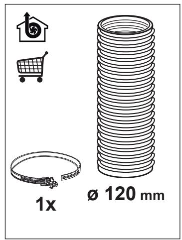
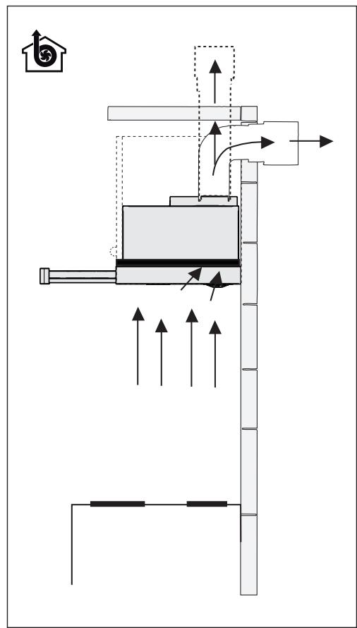
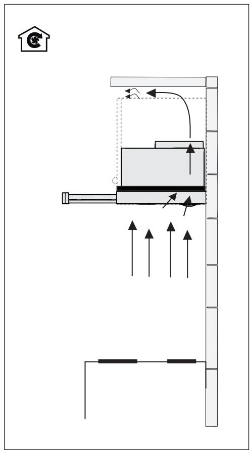
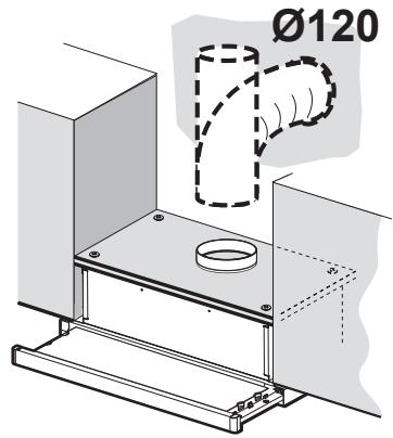
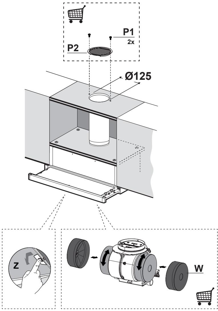
Connect the extractor to the exhaust flue through a pipe of minimum diameter 120 mm. The route of the flue must be as short as possible.
• Regulations concerning the discharge of air have to be fulfilled. - Do not connect the extractor hood to exhaust ducts carrying combustion fumes (boilers, fireplaces, etc.).
- If the extractor is used in conjunction with non-electrical appliances (e.g. gas burning appliances), a sufficient degree of aeration must be guaranteed in the room in order to prevent the backflow of exhaust gas. When the cooker hood is used in conjunction with appliances supplied with energy other than electric, the negative pressure in the room must not exceed 0,04 mbar to prevent fumes being drawn back into the room by the cooker hood.
- The air must not be discharged into a flue that is used for exhausting fumes from appliances burning gas or other fuels.
- If the supply cord is damaged, it must be replaced from the manufacturer or its service agent.
- Connect the plug to a socket complying with current regulations, located in an accessible place.
- With regards to the technical and safety measures to be adopted for fume discharging
it is important to closely follow the regulations provided by the local authorities.

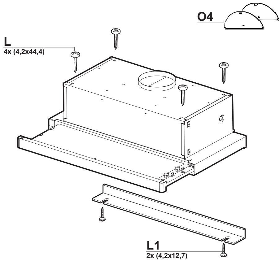
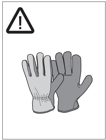
WARNING: Before installing the Hood, remove the protective films.
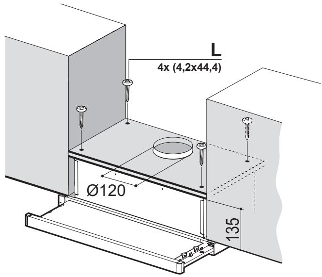
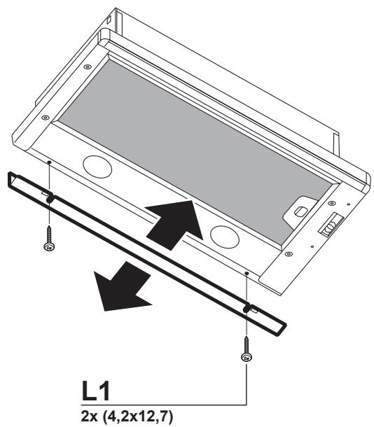
- Use only screws and small parts in support of the hood.

WARNING: Failure to install the screws or fixing device in accordance with these instructions may result in electrical hazards.
- Do not look directly at the light through optical devices (binoculars, magnifying glasses...).
- Do not flambè under the range hood; risk of fire.
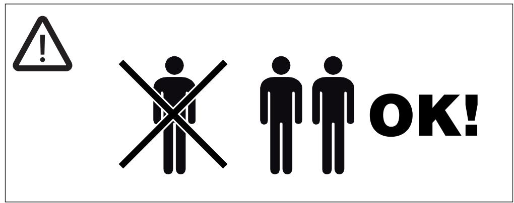
- This appliance can be used by children aged from 8 years and above and persons with reduced physical, sensory or mental capabilities or lack of experience and knowledge if they have been given supervision or instruction concerning use of the appliance in a safe way and understand the hazards involved. Children shall not play with the appliance. Cleaning and user maintenance shall not be made by children without supervision.
• Children should be supervised to ensure that they do not play with the appliance.
- The appliance is not to be used by persons (including children) with reduced physical, sensory or mental capabilities, or lack
of experience and knowledge, unless they have been given supervision or instruction.

Accessible parts may become hot when used with cooking appliances.
- Clean and/or replace the Filters after the specified time period (Fire hazard). See paragraph Care and Cleaning.
- There shall be adequate ventilation of the room when the range hood is used at the same time as appliances burning gas or other fuels (not applicable to appliances that only discharge the air back into the room).
- The symbol ✉ on the product or on its packaging indicates that this product may not be treated as household waste. Instead it shall be handed over to the applicable collection point for the recycling of electrical and electronic equipment. By ensuring this product is disposed of correctly, you will help prevent potential negative consequences for the environment and human health, which could otherwise be caused by inappropriate waste handling of this product. For more detailed information about recycling of this product, please contact your local city office, your household waste disposal service or the shop
where you purchased the product.
2. USE
- The extractor hood has been designed exclusively for domestic use to eliminate kitchen smells.
- Never use the hood for purposes other than for which it has been designed.
- Never leave high naked flames under the hood when it is in operation.
- Adjust the flame intensity to direct it onto the bottom of the pan only, making sure that it does not engulf the sides.
- Deep fat fryers must be continuously monitored during use: overheated oil can burst into flames.
3. CARE AND CLEANING
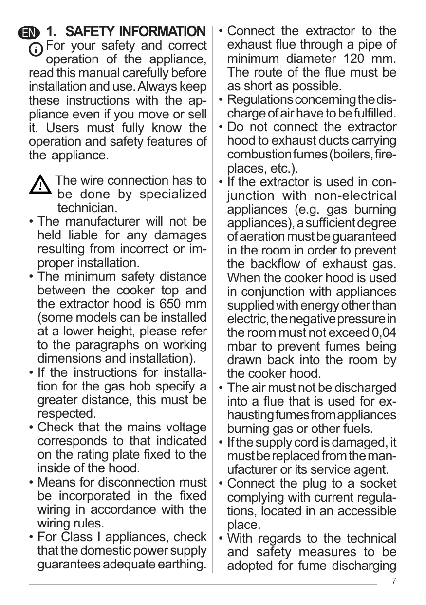
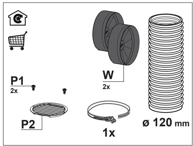
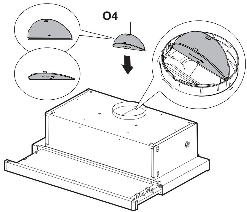
- The Activated charcoal filter is not washable and cannot be regenerated, and must be replaced approximately every 4 months of operation, or more frequently for particularly heavy usage (W).
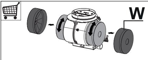
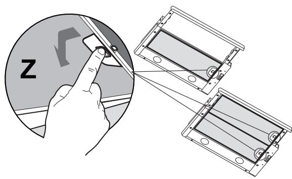
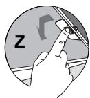
- The Grease filters must be cleaned every 2 months of operation, or more frequently for particularly heavy usage, and can be washed in a dishwasher (Z).
natural_image
Illustration of a hand holding a device with 'Z' label, no text or symbols present- Clean the hood using a damp cloth and a neutral liquid detergent.
4. CONTROLS
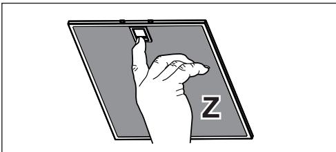
| L | Light | Switches the lighting system on and off. |
| M | Motor | Switches the extractor motor on and off. |
| V | Speed | Sets the operating speed of the extractor:1. Low speed, used for a continuous and silent air change in the presence of light cooking vapour.2. Medium speed, suitable for most operating conditions given the optimum treated air flow/noise level ratio.3. Maximum speed, used for eliminating the highest cooking vapour emission, including long periods. |
5. LIGHTING
- For replacement contact technical support ("To purchase contact technical support").
FR 1. CONSIGNES DE SÉCURITÉ
natural_image
Illustration of a hand holding a device with 'Z' label, no text or symbols presentnatural_image
Illustration of a hand holding a device with 'Z' label, no text or symbols presentEN INSTALLATION MANUAL
Warning! Before proceeding with installation, read the safety information in the User Manual.
FR MANUEL D'INSTALLATION
natural_image
Line drawing of a wrench and screwdriver crossed over a flat surface (no text or symbols)
flowchart
graph TD
    A["Input"] --> B["Component 1"]
    B --> C["Component 2"]
    C --> D["Output"]
    style A fill:#f9f,stroke:#333
    style B fill:#ccf,stroke:#333
    style C fill:#cfc,stroke:#333
    style D fill:#fcc,stroke:#333

1


2


3

4


natural_image
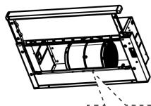
Technical line drawing of a mechanical assembly with internal components (no text or symbols)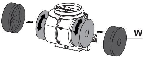
natural_image
Mechanical assembly diagram showing a cylindrical device with rotating wheels and directional arrows indicating motion (no text or symbols)

Brand : AIRLUX
Model : AHB91IX
Category : Kitchen hood