
FGC625XS - Kitchen hood FRANKE - Free user manual and instructions
Find the device manual for free FGC625XS FRANKE in PDF.
| Brand | Franke |
| Model | FGC625XS |
| Product type | Range hood |
| Installation type | Ducted or recirculating |
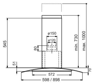
| Air outlet diameter | 150 mm (120 mm reducer included) |
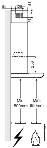
| Minimum distance from cooking surface | 650 mm |
| Number of speeds | 3 + 1 intensive speed timed (6 min) |
| Lighting | Yes (L button) |
| Grease filter type | Self-supporting metal, dishwasher safe |
| Grease filter cleaning frequency | Every 2 months |
| Charcoal filter type | Not washable, replaceable |
| Charcoal filter replacement frequency | Every 4 months |
| Electrical class | Class I (grounding mandatory) |
| Control type | Mechanical buttons |
| Chimney height | Telescopic, adjustable |
| Main material | Stainless steel |
Frequently Asked Questions - FGC625XS FRANKE
User questions about FGC625XS FRANKE
0 question about this device. Answer the ones you know or ask your own.
Ask a new question about this device
Download the instructions for your Kitchen hood in PDF format for free! Find your manual FGC625XS - FRANKE and take your electronic device back in hand. On this page are published all the documents necessary for the use of your device. FGC625XS by FRANKE.
USER MANUAL FGC625XS FRANKE
RECOMMENDATIONS AND SUGGESTIONS 3
CHARACTERISTICS 6
INSTALLATION....7
USE 10
MAINTENANCE 12
INDICE
IT
CONSIGLI E SUGGERIMENTI....13
CARATTERISTICHE....16
INSTALLAZIONE 17
USO....20
MANUTENZIONE 22
SOMMAIRE
FR
CONSEILS ET SUGGESTIONS....23
CARACTERISTIQUES....26
INSTALLATION....27
UTILISATION 30
ENTRETIEN 32
INHALTSVERZEICHNIS
DE
The Instructions for Use apply to several versions of this appliance. Accordingly, you may find descriptions of individual features that do not apply to your specific appliance.
INSTALLATION
- The manufacturer will not be held liable for any damages resulting from incorrect or improper installation.
- The minimum safety distance between the cooker top and the extractor hood is 650 mm (some models can be installed at a lower height, please refer to the paragraphs on working dimensions and installation).
- Check that the mains voltage corresponds to that indicated on the rating plate fixed to the inside of the hood.
- For Class I appliances, check that the domestic power supply guarantees adequate earthing.
Connect the extractor to the exhaust flue through a pipe of minimum diameter 120 mm. The route of the flue must be as short as possible.
- Do not connect the extractor hood to exhaust ducts carrying combustion fumes (boilers, fireplaces, etc.).
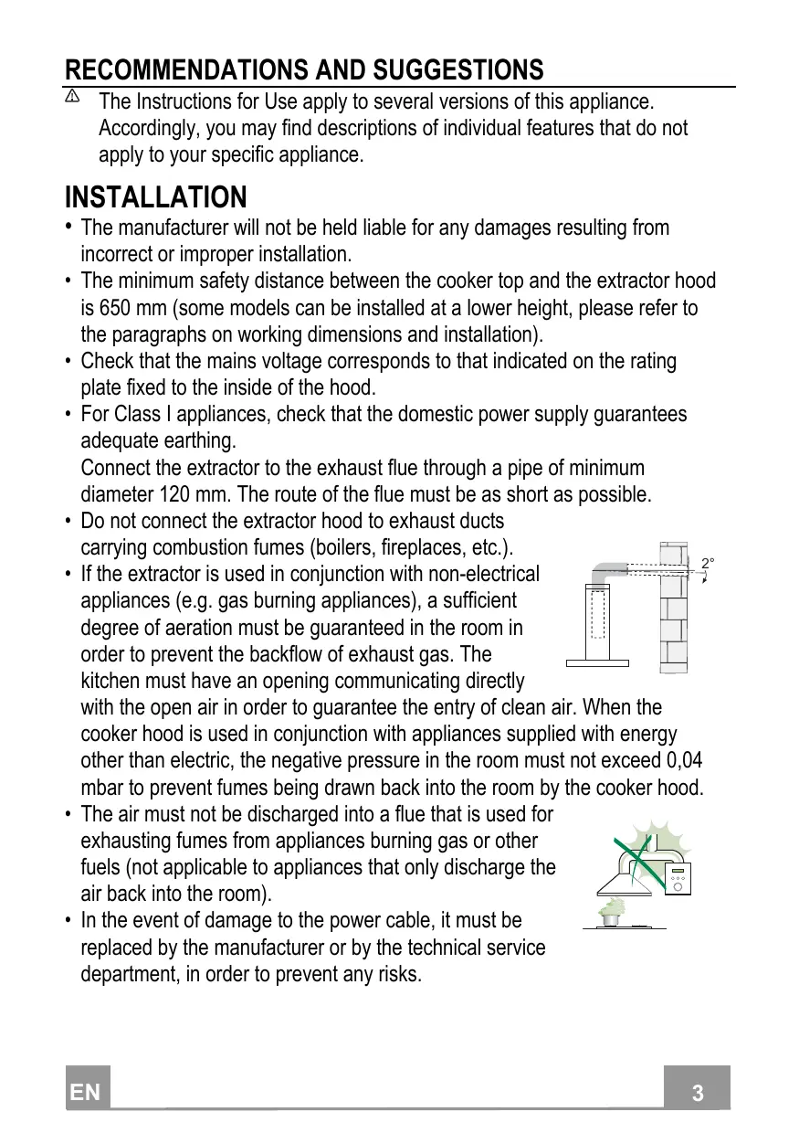
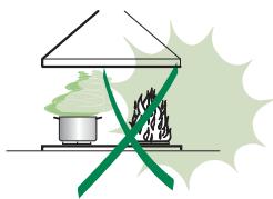
- If the extractor is used in conjunction with non-electrical appliances (e.g. gas burning appliances), a sufficient degree of aeration must be guaranteed in the room in order to prevent the backflow of exhaust gas. The kitchen must have an opening communicating directly
with the open air in order to guarantee the entry of clean air. When the cooker hood is used in conjunction with appliances supplied with energy other than electric, the negative pressure in the room must not exceed 0,04 mbar to prevent fumes being drawn back into the room by the cooker hood.
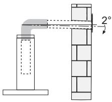
- The air must not be discharged into a flue that is used for exhausting fumes from appliances burning gas or other fuels (not applicable to appliances that only discharge the air back into the room).
- In the event of damage to the power cable, it must be replaced by the manufacturer or by the technical service department, in order to prevent any risks.
natural_image
Illustration of a chemical experiment setup with a conical flask, thermometer, and smoke rising (no text or symbols)- If the instructions for installation for the gas hob specify a greater distance specified above, this has to be taken into account. Regulations concerning the discharge of air have to be fulfilled.
- Use only screws and small parts in support of the hood.
Warning: Failure to install the screws or fixing device in accordance with these instructions may result in electrical hazards.
- Connect the hood to the mains through a two-pole switch having a contact gap of at least 3 mm.
USE
- The extractor hood has been designed exclusively for domestic use to eliminate kitchen smells.
- Never use the hood for purposes other than for which it has been designed.
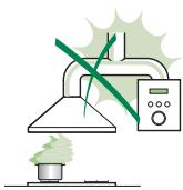
- Never leave high naked flames under the hood when it is in operation.
- Adjust the flame intensity to direct it onto the bottom of the pan only, making sure that it does not engulf the sides.
- Deep fat fryers must be continuously monitored during use: overheated oil can burst into flames.
- Do not flambè under the range hood; risk of fire.
- This appliance can be used by children aged from 8 years and above and persons with reduced physical, sensory or mental capabilities or lack of
natural_image
Illustration of a cooking setup with a pot and stove, featuring a crossed green pan and smoke (no text or symbols)experience and knowledge if they have been given supervision or instruction concerning use of the appliance in a safe way and understand the hazards involved. Children shall not play with the appliance. Cleaning and user maintenance shall not be made by children without supervision.
- This appliance is not intended for use by persons (including children) with reduced physical, sensory or mental capabilities, or lack of experience and knowledge, unless they have been given supervision or instruction concerning use of the appliance by a person responsible for their safety.
- “CAUTION: Accessible parts may become hot when used with cooking appliances.”
MAINTENANCE
- Switch off or unplug the appliance from the mains supply before carrying out any maintenance work.
- Clean and/or replace the Filters after the specified time period (Fire hazard).
- The Grease filters must be cleaned every 2 months of operation, or more frequently for particularly heavy usage, and can be washed in a dishwasher.
- The Activated charcoal filter is not washable and cannot be regenerated, and must be replaced approximately every 4 months of operation, or more frequently for particularly heavy usage.
- "Failure to carry out cleaning as indicated will result in a fire hazard".
- Clean the hood using a damp cloth and a neutral liquid detergent.
The symbol ☒ on the product or on its packaging indicates that this product may not be treated as household waste. Instead it shall be handed over to the applicable collection point for the recycling of electrical and electronic equipment. By ensuring this product is disposed of correctly, you will help prevent potential negative consequences for the environment and human health, which could otherwise be caused by inappropriate waste handling of this product. For more detailed information about recycling of this product, please contact your local city office, your household waste disposal service or the shop where you purchased the product.
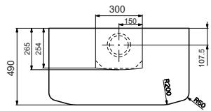
Dimensions
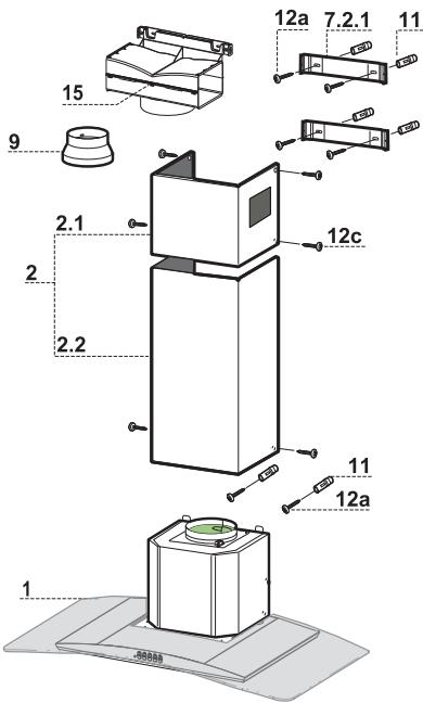
Components
| Ref. | Q.ty | Product Components |
| 1 | 1 | Hood Body, complete with: Controls, Light, Blower, Filters |
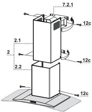
| 2 | 1 | Telescopic Chimney comprising: |
| 2.1 | 1 | Upper Section |
| 2.2 | 1 | Lower Section |
| 9 | 1 | Reducer Flange ø 150-120 mm |
| 15 | 1 | Air Outlet Connection |
| Ref. | Q.ty | Installation Components |
| 7.2.1 | 2 | Upper Chimney Section Fixing Brackets |
| 11 | 6 | Wall Plugs |
| 12a | 6 | Screws 4,2 x 44,4 |
| 12c | 6 | Screws 2,9 x 9,5 |
| Q.ty | Documentation | |
| 1 | Instruction Manual |
Wall drilling and bracket fixing
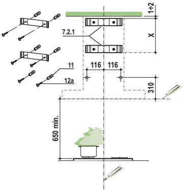
Wall marking:
- Draw a vertical line on the supporting wall up to the ceiling, or as high as practical, at the centre of the area in which the hood will be installed.
- Draw a horizontal line at 650 mm above the hob. Place bracket 7.2.1 on the wall as shown about 1-2 mm from the ceiling or upper limit aligning the centre (notch) with the vertical reference line.
- Mark the wall at the centres of the holes in the bracket.
- Place bracket 7.2.1 on the wall as shown at X mm below the first bracket (X = height of the upper chimney section supplied), aligning the centre (notch) with the vertical line.
- Mark the wall at the centres of the holes in the bracket.
- Mark a reference point as indicated at 116 mm from the vertical reference line and 310 mm above the horizontal reference line.
- Repeat this operation on the other side.
- Drill 8 mm holes at all the centre points marked.
- Insert the wall plugs 11 in the holes.
• Fix the brackets using the 12a (4,2 x 44,4) screws supplied. - Insert the two screws 12a (4,2 x 44,4) supplied in the hood body fixing holes, leaving a gap of 5-6 mm between the wall and the head of the screw.
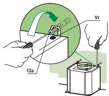
Mounting the hood body
- Before attaching the hood body, tighten the two screws Vr located on the hood body mounting points.
- Hook the hood body onto the screws 12a.
• Fully tighten the support screws 12a. - Adjust the screws Vr to level the hood body.
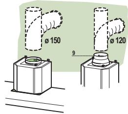
Connections
DUCTED VERSION AIR EXHAUST SYSTEM
When installing the ducted version, connect the hood to the chimney using either a flexible or rigid pipe 150 or 120 mm, the choice of which is left to the installer.
- To install a ø 120 mm air exhaust connection, insert the reducer flange 9 on the hood body outlet.
- Fix the pipe in position using sufficient pipe clamps (not supplied).
- Remove any activated charcoal filters.
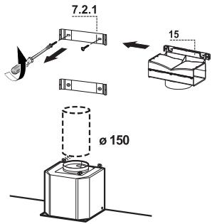
AIR OUTLET – RECIRCULATION VERSION
- Unfasten the 2 screws fixing the upper bracket 7.2.1.
- Fasten the air outlet connector 15 in its place, using the 2 screws removed as above.
- Join the Connector 15 to the Hood canopy outlet using a rigid or flexible pipe 150mm , selection of which is at the discretion of the installation technician.
- Make sure that the Activated charcoal odour filter has been fitted.
ELECTRICAL CONNECTION
- Connect the hood to the mains through a two-pole switch having a contact gap of at least 3 mm.
- Remove the grease filters (see paragraph Maintenance) being sure that the connector of the feeding cable is correctly inserted in the socket placed on the side of the fan.
natural_image
Diagram showing a mechanical assembly with a green arrow indicating direction, no text or symbols presentFlue assembly
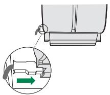
Upper exhaust flue
- Slightly widen the two sides of the upper flue and hook them behind the brackets 7.2.1, making sure that they are well seated.
- Secure the sides to the brackets by using the 4 screws 12c (2,9 x 9,5) supplied.
- Make sure that the outlet of the extensions pieces is aligned with the chimney outlets.
Lower exhaust flue
- Slightly widen the two sides of the flue and hook them between the upper flue and the wall, making sure that they are well seated.
- Fix the lower part laterally to the hood body by using the 2 screws 12c (2,9 x 9,5) supplied.
Control panel
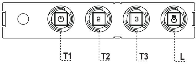
| BUTTON | LED | FUNCTIONS |
| T1 Speed | On | Turns the Motor on at Speed one. |
| Turns the Motor off. | ||
| T2 Speed | On | Turns the Motor on at Speed two. |
| T3 Speed | Fixed | When pressed briefly, turns the Motor on at Speed three. |
| L Light | Turns the Lighting System on and off. |
Warning: Button T1 turns the motor off, after first passing to speed one.
Control panel
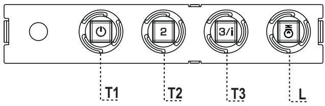
| BUTTON | LED | FUNCTIONS |
| T1 Speed | On | Turns the Motor on at Speed one. |
| Turns the Motor off. | ||
| T2 Speed | On | Turns the Motor on at Speed two. |
| T3 Speed | Fixed | When pressed briefly, turns the Motor on at Speed three. |
| Flashing | Pressed for 2 Seconds. | |
| Activates Speed four with a timer set to 6 minutes, after which it returns to the speed that was set previously. Suitable to deal with maximum levels of cooking fumes. | ||
| L Light | Turns the Lighting System on and off. |
Warning: Button T1 turns the motor off, after first passing to speed one.
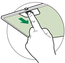
Grease filters
CLEANING METAL SELF- SUPPORTING GREASE FILTERS
- The filters must be cleaned every 2 months of operation, or more frequently for particularly heavy usage, and can be washed in a dishwasher.
- Remove the filters one at a time by pushing them towards the back of the group and pulling down at the same time.
- Wash the filters, taking care not to bend them. Allow them to dry before refitting.
- When refitting the filters, make sure that the handle is visible on the outside.
natural_image
Illustration of a hand pressing down on a smartphone screen with a green arrow indicating the left side (no text or symbols present)Activated charcoal filter (Recirculation version)
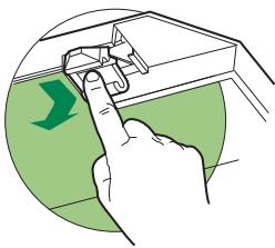
REPLACING THE ACTIVATED CHARCOAL FILTER
- The filter is not washable and cannot be regenerated, and must be replaced approximately every 4 months of operation, or more frequently for particularly heavy usage.
- Remove the metal grease filters.
- Remove the saturated activated carbon filter by releasing the fixing hooks.
- Fit the new filter by hooking it into its seating.
- Refit the metal grease filters.
natural_image
Illustration of a hand inserting a component into a device, with a green arrow indicating direction (no text or symbols)Lighting unit
- For replacement contact technical support ("To purchase contact technical support").

natural_image
Illustration of a chemical experiment setup with a conical flask, thermometer, and evaporating green material (no text or symbols)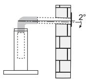
natural_image
Diagram of a pipe connection with a 2° angle indicator, showing structural components without any text or symbols.natural_image
Illustration of a cooking setup with a pot and stove, featuring a crossed green pan and smoke (no text or symbols)natural_image
Diagram showing a mechanical assembly with a highlighted section and directional arrow (no text or symbols)Montaggio Camino
Camino superiore
Quadro comandi
Quadro comandi
natural_image
Illustration of a hand pressing down on a smartphone screen with a green arrow indicating the left side (no text or symbols present)Filtro antiodore (Versione Filtrante)
SOSTITUZIONE FILTRO ANTIODORE AL CARBONE ATTIVO
natural_image
Illustration of a hand pressing down on a mechanical component with a green arrow indicating downward motion (no text or symbols)Illuminazione
natural_image
Illustration of a chemical experiment setup with a conical flask, thermometer, and smokestack (no text or symbols)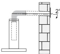
natural_image
Illustration of a pot and fire with a crossed green ribbon, no text or symbols presentnatural_image
Diagram showing a mechanical assembly with a highlighted section and directional arrow (no text or symbols)Montage Cheminée
Cheminée supérieure
natural_image
Illustration of a hand pressing down on a smartphone screen with a green arrow indicating the left side (no text or symbols present)Filtre anti-odeur (Version filtrante)
REPLACEMENT FILTRE AU CHARBON ACTIF
natural_image
Illustration of a hand pressing down on a mechanical component with a green arrow indicating downward motion (no text or symbols)Éclairage
natural_image
Illustration of a chemical experiment setup with a conical flask, thermometer, and smokestack (no text or symbols)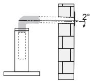
natural_image
Illustration of a cooking setup with a pot, stove, and steam rising (no text or symbols)natural_image
Diagram showing a mechanical assembly with a green arrow indicating direction, no text or symbols presentKaminmontage
Oberer Kaminteil
Schalttafel
Schalttafel
natural_image
Illustration of a hand pressing down on a smartphone screen with a green arrow indicating the left side (no text or symbols present)Geruchsfilter (Umluftversion)
natural_image
Illustration of a hand inserting a component into a device, with a green arrow indicating direction (no text or symbols)Beleuchtung
LED-Strahler
natural_image
Illustration of a chemical experiment setup with a funnel, reaction flask, and control panel (no text or symbols)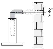
natural_image
Illustration of a cooking setup with a pot and stove, featuring a crossed green pan and smoke (no text or symbols)natural_image
Diagram showing a mechanical assembly with a green arrow indicating direction, no text or symbols presentBacanın montajı
Üst baca
Kumanda Tablosu
Kumanda Tablosu
natural_image
Illustration of a hand pressing down on a smartphone screen with a green arrow indicating the left side (no text or symbols present)Koku Filtresi (Filtreli Model)
AKTİF KARBONLU KOKU FİLTRESİNİN DEĞİŞTİRİLMESİ
natural_image
Illustration of a hand inserting a component into a device, with a green arrow indicating direction (no text or symbols)Aydınlatma
natural_image
Illustration of a chemical experiment setup with a conical flask, thermometer, and smokestack (no text or symbols)
natural_image
Diagram of a pipe connection with a 2° angle indicator (no text or symbols present)natural_image
Illustration of a cooking pot with steam rising, crossed by a green diagonal line (no text or symbols)CONEXIUNEA ELECTRICĂ
natural_image
Diagram showing a mechanical assembly with a highlighted section and directional arrow (no text or symbols)Montarea hornului
Hornul superior
Tabloul de comandă
Tablou de comandă
natural_image
Illustration of a hand pressing down on a smartphone screen with a green arrow indicating the left side (no text or symbols present)natural_image
Illustration of a hand inserting a component into a device, with a green arrow indicating direction (no text or symbols)Illuminat
- INDICE
- IT
- SOMMAIRE
- FR
- INHALTSVERZEICHNIS
- DE
- INSTALLATION
- USE
- MAINTENANCE
- Dimensions
- Wall drilling and bracket fixing
- Wall marking:
- Mounting the hood body
- Connections
- DUCTED VERSION AIR EXHAUST SYSTEM
- AIR OUTLET – RECIRCULATION VERSION
- ELECTRICAL CONNECTION
- Flue assembly
- Upper exhaust flue
- Lower exhaust flue
- Grease filters
- CLEANING METAL SELF- SUPPORTING GREASE FILTERS
- Activated charcoal filter (Recirculation version)
- REPLACING THE ACTIVATED CHARCOAL FILTER
- Lighting unit
- Montaggio Camino
- Camino superiore
- Filtro antiodore (Versione Filtrante)
- SOSTITUZIONE FILTRO ANTIODORE AL CARBONE ATTIVO
- Illuminazione
- Montage Cheminée
- Cheminée supérieure
- Filtre anti-odeur (Version filtrante)
- REPLACEMENT FILTRE AU CHARBON ACTIF
- Éclairage
- Kaminmontage
- Oberer Kaminteil
- Geruchsfilter (Umluftversion)
- Beleuchtung
- LED-Strahler
- Bacanın montajı
- Üst baca
- Koku Filtresi (Filtreli Model)
- AKTİF KARBONLU KOKU FİLTRESİNİN DEĞİŞTİRİLMESİ
- Aydınlatma
- CONEXIUNEA ELECTRICĂ
- Montarea hornului
- Hornul superior
- Illuminat
Brand : FRANKE
Model : FGC625XS
Category : Kitchen hood