
P3000R - Audio Preamplifier ONKYO - Free user manual and instructions
Find the device manual for free P3000R ONKYO in PDF.

| Product type | Audio preamplifier |
| Brand | ONKYO |
| Model | P3000R |
| Dimensions (W × H × D) | 435 mm × 100 mm × 300 mm |
| Weight | 8.0 kg |
| Power supply | 230 V AC, 50 Hz |
| Power consumption | 35 W |
| Number of audio inputs | 6 (CD, Tuner, AUX, Phono, Tape 1, Tape 2) |
| Audio outputs | 2 (Pre Out, Tape Rec) |
| Frequency response | 10 Hz - 100 kHz ± 1 dB |
| Signal-to-noise ratio | 100 dB |
| Total harmonic distortion | 0.003 % |
| Input impedance | 50 kΩ (line), 47 kΩ (phono) |
| Output impedance | 600 Ω |
| Main functions | Source selection, volume control, balance, bass/treble, subsonic filter, mute |
| Maintenance and cleaning | Use a soft, dry cloth. Do not use chemical products. |
| Safety | Do not expose to moisture or splashes. Disconnect before cleaning. |
| Spare parts and repairability | Contact ONKYO customer service for spare parts and repairs. |
| General information | Audiophile preamplifier designed for high-quality sound reproduction. |
Frequently Asked Questions - P3000R ONKYO
User questions about P3000R ONKYO
0 question about this device. Answer the ones you know or ask your own.
Ask a new question about this device
Download the instructions for your Audio Preamplifier in PDF format for free! Find your manual P3000R - ONKYO and take your electronic device back in hand. On this page are published all the documents necessary for the use of your device. P3000R by ONKYO.
USER MANUAL P3000R ONKYO
TO REDUCE THE RISK OF FIRE OR ELECTRIC SHOCK, DO NOT EXPOSE THIS APPARATUS TO RAIN OR MOISTURE.
CAUTION:
TO REDUCE THE RISK OF ELECTRIC SHOCK, DO NOT REMOVE COVER (OR BACK). NO USER-SERVICEABLE PARTS INSIDE. REFER SERVICING TO QUALIFIED SERVICE PERSONNEL.

WARNING
RISK OF ELECTRIC SHOCK DO NOT OPEN
AVIS
RISQUE DE CHOC ELECTRIQUE NE PAS OUVRIR


The lightning flash with arrowhead symbol, within an equilateral triangle, is intended to alert the user to the presence of uninsulated “dangerous voltage” within the product’s enclosure that may be of sufficient magnitude to constitute a risk of electric shock to persons.

The exclamation point within an equilateral triangle is intended to alert the user to the presence of important operating and maintenance (servicing) instructions in the literature accompanying the appliance.
Important Safety Instructions
- Read these instructions.
- Keep these instructions.
- Heed all warnings.
- Follow all instructions.
- Do not use this apparatus near water.
- Clean only with dry cloth.
- Do not block any ventilation openings. Install in accordance with the manufacturer's instructions.
- Do not install near any heat sources such as radiators, heat registers, stoves, or other apparatus (including amplifiers) that produce heat.
- Do not defeat the safety purpose of the polarized or grounding-type plug. A polarized plug has two blades with one wider than the other. A grounding type plug has two blades and a third grounding prong. The wide blade or the third prong are provided for your safety. If the provided plug does not fit into your outlet, consult an electrician for replacement of the obsolete outlet.
- Protect the power cord from being walked on or pinched particularly at plugs, convenience receptacles, and the point where they exit from the apparatus.
-
Only use attachments/accessories specified by the manufacturer.
-
Use only with the cart, stand, tripod, bracket, or table specified by the manufacturer, or sold with the apparatus. When a cart is used, use caution when moving the cart/apparatus combination to avoid injury from tip-over.
-
Unplug this apparatus during lightning storms or when unused for long periods of time.
- Refer all servicing to qualified service personnel. Servicing is required when the apparatus has been damaged in any way, such as power-supply cord or plug is damaged, liquid has been spilled or objects have fallen into the apparatus, the apparatus has been exposed to rain or moisture, does not operate normally, or has been dropped.
- Damage Requiring Service Unplug the apparatus from the wall outlet and refer servicing to qualified service personnel under the following conditions:
A. When the power-supply cord or plug is damaged,
B. If liquid has been spilled, or objects have fallen into the apparatus,
C. If the apparatus has been exposed to rain or water,
D. If the apparatus does not operate normally by following the operating instructions. Adjust only those controls that are covered by the operating instructions as an improper adjustment of other controls may result in damage and will often
PORTABLE CART WARNING

require extensive work by a qualified technician to restore the apparatus to its normal operation,
E. If the apparatus has been dropped or damaged in any way, and
F. When the apparatus exhibits a distinct change in performance this indicates a need for service.
- Object and Liquid Entry
Never push objects of any kind into the apparatus through openings as they may touch dangerous voltage points or short-out parts that could result in a fire or electric shock.
The apparatus shall not be exposed to dripping or splashing and no objects filled with liquids, such as vases shall be placed on the apparatus.
Don't put candles or other burning objects on top of this unit.
- Batteries
Always consider the environmental issues and follow local regulations when disposing of batteries.
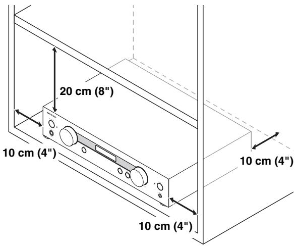
- If you install the apparatus in a built-in installation, such as a bookcase or rack, ensure that there is adequate ventilation.
Leave 20 cm (8") of free space at the top and sides and 10 cm (4") at the rear. The rear edge of the shelf or board above the apparatus shall be set 10 cm (4") away from the rear panel or wall, creating a flue-like gap for warm air to escape.
Precautions
-
Recording Copyright—Unless it's for personal use only, recording copyrighted material is illegal without the permission of the copyright holder.
-
AC Fuse—The AC fuse inside the unit is not user-serviceable. If you cannot turn on the unit, contact your Onkyo dealer.
-
Care—Occasionally you should dust the unit all over with a soft cloth. For stubborn stains, use a soft cloth dampened with a weak solution of mild detergent and water. Dry the unit immediately afterwards with a clean cloth. Don’t use abrasive cloths, thinners, alcohol, or other chemical solvents, because they may damage the finish or remove the panel lettering.
-
Power
WARNING
BEFORE PLUGGING IN THE UNIT FOR THE FIRST TIME, READ THE FOLLOWING SECTION CAREFULLY.
AC outlet voltages vary from country to country. Make sure that the voltage in your area meets the voltage requirements printed on the unit's rear panel (e.g., AC 230 V, 50 Hz or AC 120 V, 60 Hz).
The power cord plug is used to disconnect this unit from the AC power source. Make sure that the plug is readily operable (easily accessible) at all times.
Pressing the [POWER] button to select OFF mode does not fully disconnect from the mains. If you do not intend to use the unit for an extended period, remove the power cord from the AC outlet.
- Preventing Hearing Loss
Caution
Excessive sound pressure from earphones and headphones can cause hearing loss.
- Batteries and Heat Exposure
Warning
Batteries (battery pack or batteries installed) shall not be exposed to excessive heat as sunshine, fire or the like.
-
Never Touch this Unit with Wet Hands—Never handle this unit or its power cord while your hands are wet or damp. If water or any other liquid gets inside this unit, have it checked by your Onkyo dealer.
-
Handling Notes
-
If you need to transport this unit, use the original packaging to pack it how it was when you originally bought it.
- Do not leave rubber or plastic items on this unit for a long time, because they may leave marks on the case.
- This unit's top and rear panels may get warm after prolonged use. This is normal.
- If you do not use this unit for a long time, it may not work properly the next time you turn it on, so be sure to use it occasionally.
For U.S. models
FCC Information for User
CAUTION:
The user changes or modifications not expressly approved by the party responsible for compliance could void the user's authority to operate the equipment.
NOTE:
This equipment has been tested and found to comply with the limits for a Class B digital device, pursuant to Part 15 of the FCC Rules. These limits are designed to provide reasonable protection against harmful interference in a residential installation.
This equipment generates, uses and can radiate radio frequency energy and, if not installed and used in accordance with the instructions, may cause harmful interference to radio communications. However, there is no guarantee that interference will not occur in a particular installation. If this equipment does cause harmful interference to radio or television reception, which can be determined by turning the equipment off and on, the user is encouraged to try to correct the interference by one or more of the following measures:
- Reorient or relocate the receiving antenna.
- Increase the separation between the equipment and receiver.
- Connect the equipment into an outlet on a circuit different from that to which the receiver is connected.
- Consult the dealer or an experienced radio/TV technician for help.
For Canadian Models
NOTE:
THIS CLASS B DIGITAL APPARATUS COMPLIES WITH CANADIAN ICES-003.
For models having a power cord with a polarized plug:
CAUTION:
TO PREVENT ELECTRIC SHOCK, MATCH WIDE BLADE OF PLUG TO WIDE SLOT, FULLY INSERT.
Replacement and mounting of an AC plug on the power supply cord of this unit should be performed only by qualified service personnel.
IMPORTANT
The wires in the mains lead are coloured in accordance with the following code:
Blue: Neutral
Brown: Live
As the colours of the wires in the mains lead of this apparatus may not correspond with the coloured markings identifying the terminals in your plug, proceed as follows: The wire which is coloured blue must be connected to the terminal which is marked with the letter N or coloured black.
The wire which is coloured brown must be connected to the terminal which is marked with the letter L or coloured red.
IMPORTANT
The plug is fitted with an appropriate fuse. If the fuse needs to be replaced, the replacement fuse must approved by ASTA or BSI to BS1362 and have the same ampere rating as that indicated on the plug. Check for the ASTA mark or the BSI mark on the body of the fuse.
If the power cord's plug is not suitable for your socket outlets, cut it off and fit a suitable plug. Fit a suitable fuse in the plug.
For European Models
Declaration of Conformity
We, ONKYO EUROPE
ELECTRONICS GmbH LIEGNITZERSTRASSE 6, 82194 GROEBENZELL, GERMANY

declare in own responsibility, that the ONKYO product described in this instruction manual is in compliance with the corresponding technical standards such as EN60065, EN55013, EN55020 and EN61000-3-2, -3-3.
GROEBENZELL, GERMANY

ONKYO EUROPE ELECTRONICS GmbH
Features
- DIDRC (Dynamic Intermodulation Distortion Reduction Circuitry)
- Separate Digital/Analog Circuitry
- Separate Massive Transformers for Digital/Analog Circuitry (Toroidal Transformer for Analog Circuitry)
- Separate Anti-Vibration Aluminum Panels for Top, Front, and Sides
- Side-mounted Circuit Board Construction to Reduce Vibration
- PLL Ultra-Low Jitter Technology
- Sampling Rate Converter (Up to 192 kHz)
- Separate TI (Burr-Brown) 192 kHz/32-Bit DACs (PCM1795) for L/R Channels
- Direct Mode
• Tone Control (Bass/Treble)
• Independent Headphone Amplifier - Discrete Phono Equalizer
- Phono Input (MM)
- USB Digital Input for 192 kHz/32-Bit HD Audio from PC*
- AES/EBU Balanced Digital Input with XLR Connector
- 5 Digital Inputs (2 Optical, 2 Coaxial and 1 AES/EBU) and 1 Optical Output
- Separate L/R Bi-Amping-Capable Pre-Outs
• Gold-Plated, Machined Solid Brass, 19 mm-Pitch Audio Terminals - 12 V Trigger Out
- Display Dimmer (Normal/Dim/Off)
Technologies
DIDRC (Dynamic Intermodulation Distortion Reduction Circuitry)
Since the advent of digital audio, the values of S/N (signal-to-noise) ratio have risen significantly. However, it is also recognized that in terms of perceived S/N, analog audio sources are not inferior to digital sources.
Generally, S/N measures the ratio when sound is and not produced, but takes no account of the noise generated during sound reproduction.
For a long time, Onkyo has focused and made extensive research on the S/N when sound is produced (dynamic S/N). Using a mechanism that captures the noise beyond audible range, it has been possible to determine that both dynamic S/N and perceived S/N aggravate during music reproduction.
Although frequencies above 20 kHz are beyond human hearing, it is well known that a beat can be perceived if different signals are overlapped at such frequencies.
During the analog audio era, no significant signals were entering beyond the audible range. However, the digital era has made recording beyond the audible range possible and the generated beat is now perceivable.
With Onkyo's DIDRC technology, a new approach is introduced which prevents such beat from penetrating the audible range.
Separate Digital/Analog Circuitry and Transformers
To prevent unwanted interference, the P-3000R employs physically separate circuitry for digital and analog processing. What's more, it also features separate transformers for digital and analog circuitry.
Playback of Various Music Sources Including PC Audio via USB
Using the USB port on the rear panel of the P-3000R, you can connect your PC and play back 192 kHz/32-bit HD audio formats*.
* Playback of PC audio requires dedicated software that can be downloaded from an Onkyo website.
PLL (Phase Locked Loop) Ultra-Low Jitter Technology
Jitter is an unwanted side-effect of the digital-to-analog conversion process caused by fluctuations in the time domain of a digital signal. PLL ultra-low jitter technology reduces jitter by comparing the input and output phases of the digital signal and creating an accurate clock waveform. This enhances the precision of digital signal processing and noticeably improves perceived audio quality.
Side-mounted Circuit Board Construction
Rather than being directly connected to the chassis base, the circuit boards inside the P-3000R are cushioned by internal struts and affixed to the front, side, and rear panels. This method of construction prevents vibrations from the chassis from adversely affecting the circuit boards.
Block Diagram

DIDRC
(Dynamic Intermodulation Distortion Reduction Circuitry)
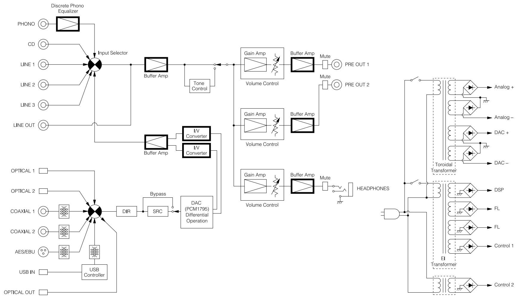
flowchart
graph TD
    A["Input Selector"] --> B["Discrete Phono Equalizer"]
    A --> C["Buffer Amp"]
    C --> D["Tone Control"]
    D --> E["Volume Control"]
    E --> F["Buffer Amp"]
    F --> G["Mute"]
    G --> H["PRE OUT 1"]
    F --> I["Mute"]
    I --> J["PRE OUT 2"]
    K["OPTICAL 1"] --> L["USB Controller"]
    M["OPTICAL 2"] --> L
    N["COAXIAL 1"] --> O["RSRC"]
    P["COAXIAL 2"] --> Q["RSRC"]
    R["AES/EBU"] --> S["RSRC"]
    T["USB IN"] --> U["RSRC"]
    V["OPTICAL OUT"] --> W["RSRC"]
    X["DIScrete Phono Equalizer"] --> A
    Y["Line 1"] --> A
    Z["Line 2"] --> A
    AA["LINE OUT"] --> A
    AB["Bypass"] --> AC["DAC (PCM1795) Differential Operation"]
    AD["DIR"] --> AE["SRC"]
    AF["I/V Converter"] --> AG["I/V Converter"]
    AH["Gain Amp"] --> AI["Volume Control"]
    AJ["Gain Amp"] --> AK["Volume Control"]
    AL["Gain Amp"] --> AM["Volume Control"]
    AN["Volume Control"] --> AO["Mute"]
    AP["Headphones"] --> AQ["Diode"]
    AR["Toroidal Transformer"] --> AS["DSP"]
    AT["FI"] --> AU["FL"]
    AV["Control 1"] --> AW["Control 1"]
    AX["EI"] --> AY["Transformer"]
    AZ["Control 2"] --> BA["Control 2"]
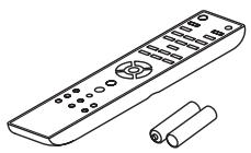
Supplied Accessories
Make sure you have the following accessories:
Remote controller and two batteries
Remote controller (RC-797S) .....(1)
Batteries (R03/AAA) ..... (2)
Power cord
Power cord (1.8 m/5.9 ft) ..... (1)
(Plug type varies from country to country.)
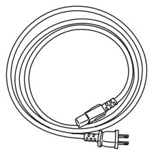
natural_image
Line drawing of a coiled electrical cable with two terminal connectors (no text or symbols)* In catalogs and on packaging, the letter at the end of the product name indicates the color.
Specifications and operations are the same regardless of color.
Thank you for purchasing an Onkyo Preamplifier. Please read this manual thoroughly before making connections and plugging in the unit.
Following the instructions in this manual will enable you to obtain optimum performance and listening enjoyment from your new Preamplifier.
Please retain this manual for future reference.
Contents
Introduction
Important Safety Instructions ....2
Precautions....3
Features ....5
Technologies 6
Block Diagram....7
Supplied Accessories....8
Before Using the Preamplifier....10
Installing the Batteries ....10
Using the Remote Controller ....10
Installing the Preamplifier ....10
Getting to Know the Preamplifier ....11
Front Panel 11
Display 12
Rear Panel....13
Remote Controller....14
Connections
Connections 15
Cable and Jacks 15
Connecting the Power Cord....16
Connecting a Compact Disc Player....17
Connecting the Onkyo Dock....18
Connecting a Turntable 19
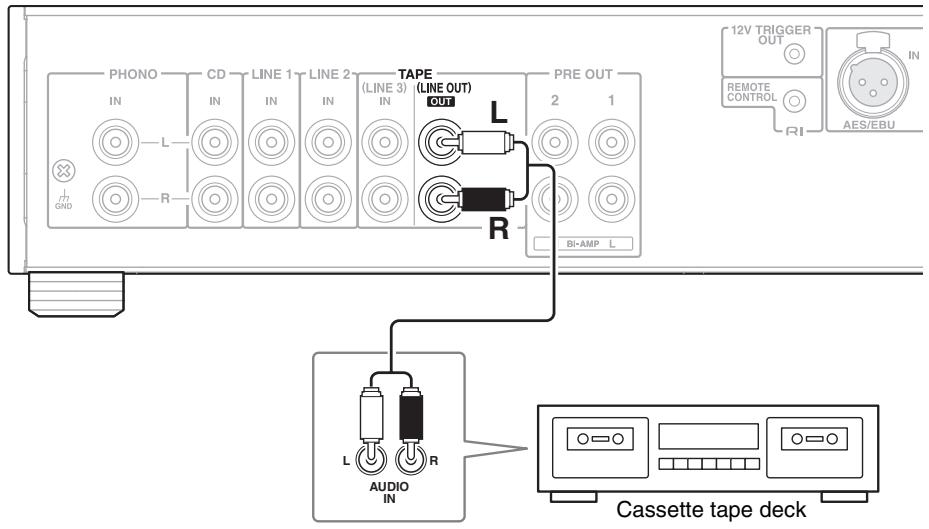
Connecting a Cassette Tape Deck....19
Connecting a Recording Component....19
Connecting a Power Amplifier ....20
Turning On & Basic Operations
Basic Operations....25
Turning On/Off the Preamplifier....25
Adjusting the Volume....26
Selecting the Input Source....26
Hiding the Digital Source Display 26
Adjusting the Bass, Treble and Balance....27
Muting the Sound....27
Using the Direct Function ......28
Adjusting the Display Brightness 28
Changing the Display information....28
Using Headphones 29
Using MODE button....29
Playing the Onkyo Compact Disc Player 30
Playback 30
Playing Music Files on the PC 31
Connecting the PC....31
Installing a USB Driver....31
Playing Music Files on the PC 31
Controlling iPod & Other Components
Using an Onkyo Dock....32
Playing Music Files on iPod....32
Onkyo Dock 32
Advanced Operations
Custom Setup....33
Changing the Selector Name ....33
Selecting the Sampling Rate Conversion....33
Setting the Bi-amp Level 33
Setting the Headphone Level 34
Selecting the Analog Audio Out....34
Setting ASb (Auto Standby)....35
LINE 2 Output with a Fixed Volume ....35
Others
Troubleshooting....36
Specifications....38
Before Using the Preamplifier
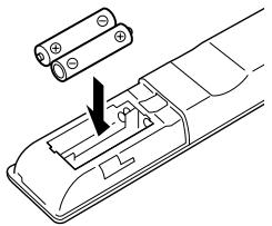
Installing the Batteries
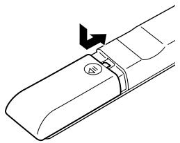
1 To open the battery compartment, press the small hollow and slide the cover.
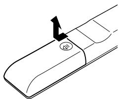
natural_image
Line drawing of a car door handle with a black arrow pointing to the left side (no text or symbols)2 Insert the two supplied batteries (R03/AAA) in accordance with the polarity diagram inside the battery compartment.
natural_image
Diagram of a car interior showing battery pack and switch mechanism (no text or symbols)3 Replace the cover and slide it shut.
natural_image
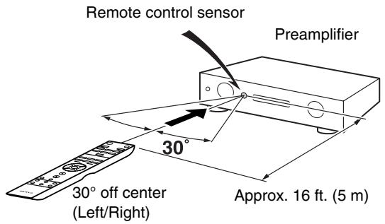
Line drawing of a mechanical component with a directional arrow indicating motion (no text or symbols)Using the Remote Controller
To use the remote controller, point it at the preamplifier's remote control sensor, as shown below.
Note
- The remote controller may not work reliably if the preamplifier is subjected to bright light, such as direct sunlight or inverter-type fluorescent lights. Keep this in mind when installing.
- If another remote controller of the same type is used in the same room, or the preamplifier is installed close to equipment that uses infrared rays, the remote controller may not work reliably.
- Don't put anything, such as a book, on the remote controller, because the buttons may be pressed inadvertently, thereby draining the batteries.
- The remote controller may not work reliably if the preamplifier is installed in a rack behind colored glass doors. Keep this in mind when installing.
- The remote controller will not work if there's an obstacle between it and the preamplifier's remote control sensor.
Installing the Preamplifier
Install the preamplifier on a sturdy rack or shelf. Position it so that its weight is evenly dispersed on its four legs. Do not install the preamplifier in a place with vibration or an unstable location.
Note
- If the remote controller doesn't work reliably, try replacing the batteries.
- Don't mix new and old batteries or different types of batteries.
- If you intend not to use the remote controller for a long time, remove the batteries to prevent damage from leakage or corrosion.
- Remove expired batteries as soon as possible to prevent damage from leakage or corrosion.
Getting to Know the Preamplifier
Front Panel
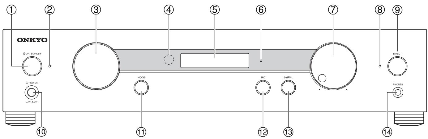
The page numbers in parentheses show where you can find the main explanation for each item.
① ON/STANDBY button ( 25)
Sets the preamplifier to On or Standby.
② Standby LED ( 25)
Lights when the preamplifier is in Standby mode.
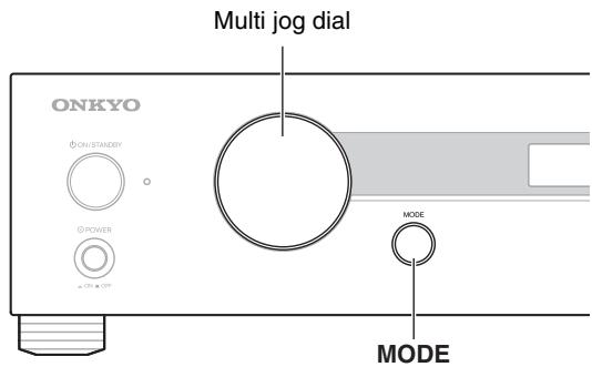
③ Multi jog dial ( 29)
Selects the input sources in sequence. The input sources are “CD”, “LINE 1”, “LINE 2”, “LINE 3”, “COAX1”, “COAX2”, “OPT1”, “OPT2”, “AES/EBU”, “USB”*, “PHONO”.
It is also used for various settings.
* You can select USB input only when the USB connector is connected.
④ Remote control sensor ( 10)
The sensor receives control signals from the remote controller.
⑤ Display ( 12)
See “Display”.
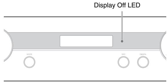
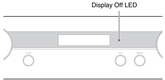
⑥ Display Off LED ( 28)
Lights when the display is turned off.
Before entering standby mode with the ASb function, the Display Off LED flashes 30 seconds before the ASb function starts running.
⑦ Volume controller ( 26)
You can set the volume.
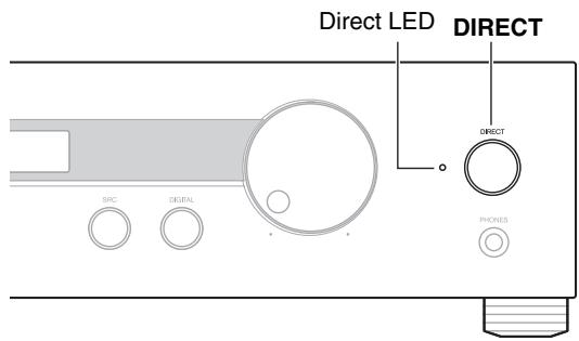
⑧ Direct LED ( 28)
Lights when the preamplifier is in Direct mode.
⑨ DIRECT button ( 28)
Selects the Direct mode. Pressing this button again cancels the Direct mode.
⑩ POWER switch ( 25)
This is the main power switch. When set to the OFF position (■), the preamplifier is completely shutdown. It must be set to the ON position (■) to set the preamplifier to On or Standby.
⑪ MODE button ( 29)
Press this button to start the following settings:
“BASS”, “TREBLE”, “BALANCE”, “BIAMP”,
“HPLEVEL (headphone level)”, “LINEOUT (or
RECOUT)", "ASb (Auto Standby)", "L2 OUT".
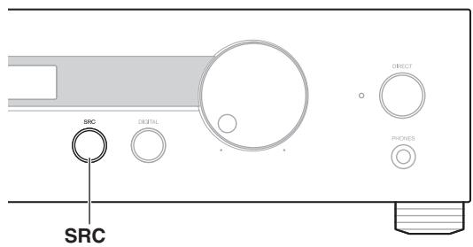
⑫ SRC (Sampling Rate Converter) button ( 33)
This button is used to convert the sampling rate of the input digital signal: “BYPASS (no conversion)”, “FS x2”, “FS x4”.

Note
- The USB input does not support FS x4 (→ 31).
⑬ DIGITAL button ( 26)
This button is used to turn the digital input source display on or off.
⑭ PHONES jack ( 29, 34)
Stereo headphones with a standard plug can be plugged into this jack.
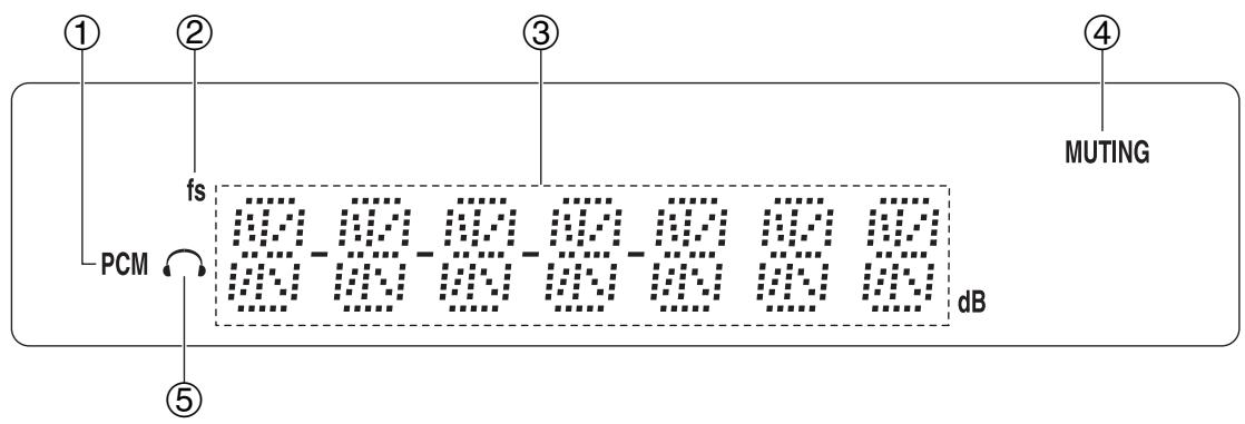
For detailed information, see the pages in parentheses.
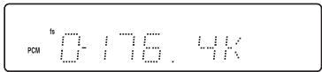
① PCM indicator
Lights when it detects digital audio signal input. It blinks when nothing is detected.
② fs indicator ( 28)
Lights when sampling rate is displayed.
③ Message area
Displays various information.
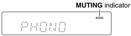
④ MUTING indicator ( 27)
Flashes while the preamplifier is muted.
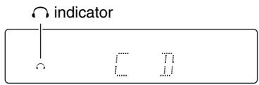
⑤ Headphone indicator ( 29)
Lights when a pair of headphones are plugged into the PHONES jack.
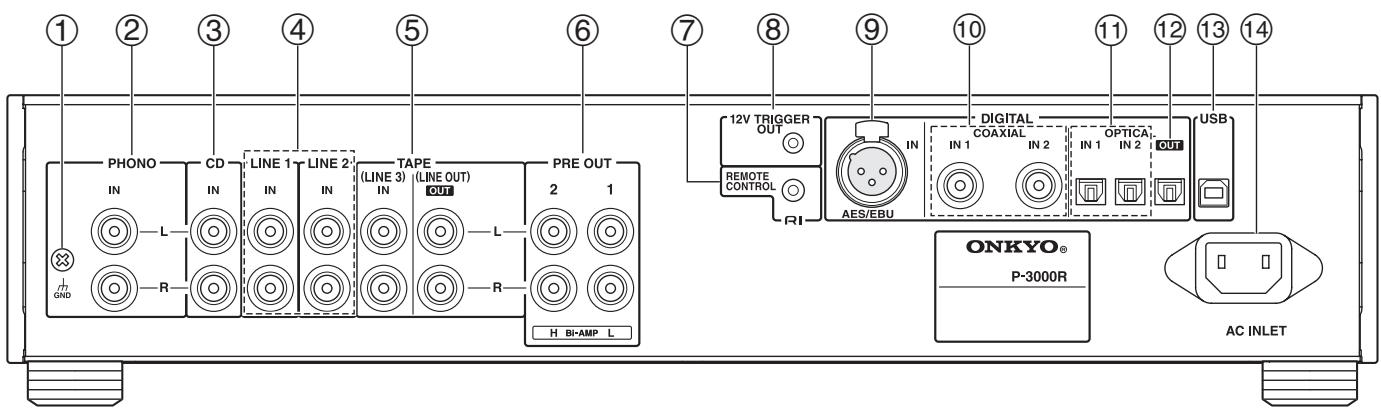
① GND screw
This screw is for connecting a turntable's ground wire.
② PHONO IN L/R jacks
These analog audio inputs are for connecting a turntable (MM).
③ CD IN L/R jacks
These analog audio inputs are for connecting a compact disc player.
④ LINE 1/2 IN L/R jacks
These analog audio inputs are for connecting a playback device.
To input audio output (preout) to the preamplifier from the AV receiver, set “L2 OUT” to
"THROUGH". The PRE OUT output of the preamplifier is fixed at 0 dB.
You can output the audio signal coming from LINE 2 with a fixed volume ( 35).
⑤ TAPE IN (LINE 3 IN) and TAPE OUT (LINE OUT) jacks
These analog audio inputs and outputs are for connecting a cassette tape deck.
⑥ PRE OUT 1/2 L/R jacks
These outputs are for connecting a power amplifier.
⑦ RI REMOTE CONTROL jack
This RI (Remote Interactive) jack can be connected to an RI jack on an Onkyo Dock. The preamplifier's remote controller can then be used to control the Onkyo Dock.
To use RI, you must make an audio connection between the preamplifier and the Onkyo Dock. Other Onkyo components cannot be controlled via RI.
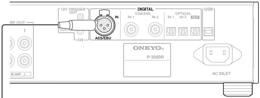
⑧ 12V TRIGGER OUT jack
This output can be connected to the 12-volt trigger inputs on the power amplifier.
⑨ DIGITAL AES/EBU IN jack
This balanced AES/EBU input is for connecting a component with balanced AES/EBU output, such as compact disc players.
⑩ DIGITAL COAXIAL IN 1/2 jacks
These coaxial digital audio inputs are for connecting components with coaxial digital audio outputs, such as compact disc players.
⑪ DIGITAL OPTICAL IN 1/2 jacks
These optical digital audio inputs are for connecting components with optical digital audio outputs, such as compact disc players.
⑫ DIGITAL OPTICAL OUT jack
This optical digital audio output is for connecting an AV receiver.
Digital input signals are put through and output on this preamplifier as is.
⑬ USB port
A PC can be connected here and the music can be played through the preamplifier.
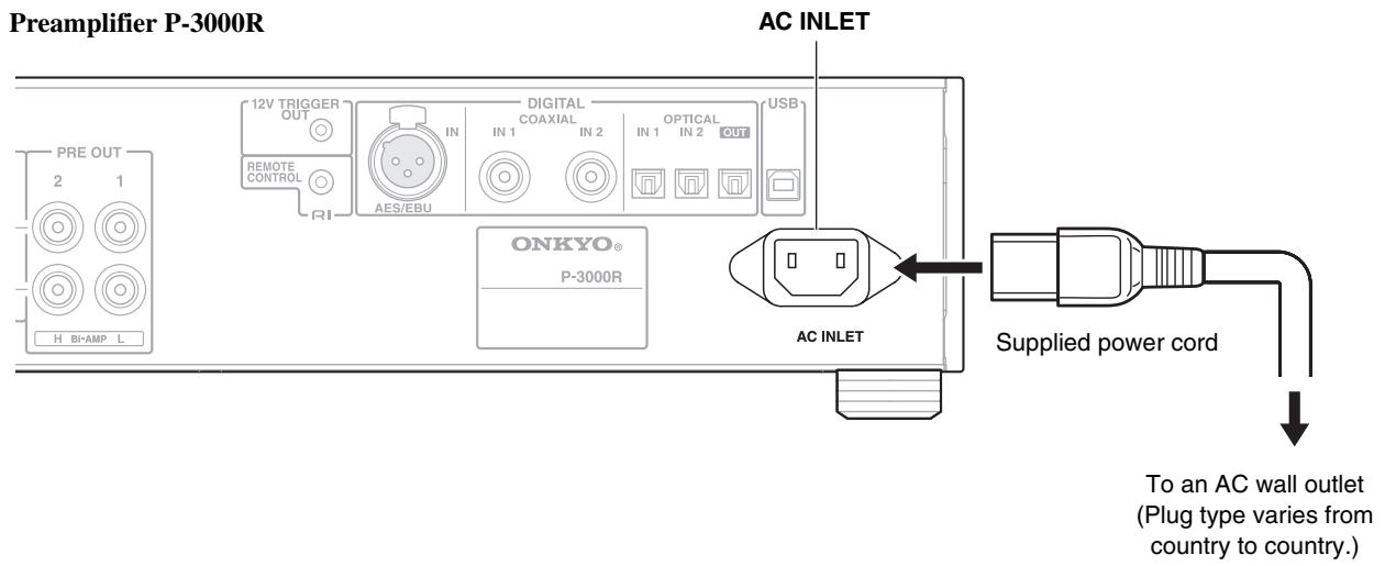
⑭ AC INLET
The supplied power cord is connected here. The other end of the power cord should be connected to a suitable wall outlet.
See “Connections” for connection information ( 15 to 24).
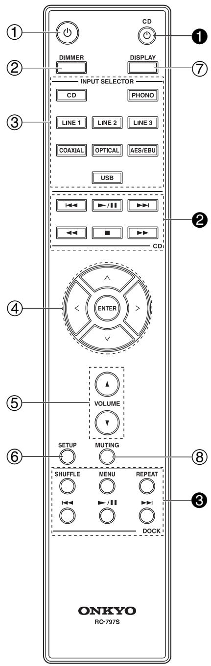
For detailed information, see the pages in parentheses.
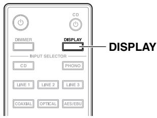
① ⏻ button ( 25)
Sets the preamplifier to On or Standby.
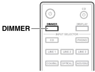
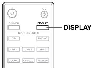
② DIMMER button ( 28)
Adjusts the display brightness.
③ INPUT SELECTOR buttons (CD, PHONO, LINE 1, LINE 2, LINE 3, COAXIAL, OPTICAL, AES/EBU, USB) ( 26)
Selects an input source.
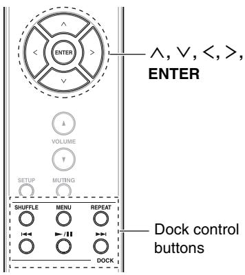
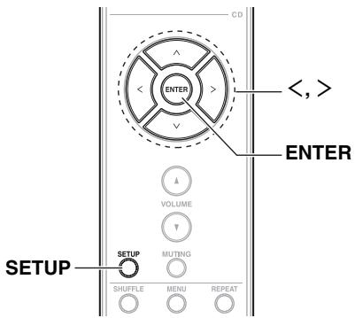
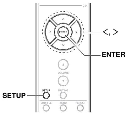
④ ∧/∨/</> and ENTER buttons
Used to select and adjust settings.
⑤ VOLUME ▲/▼ button (→ 26)
Adjusts the volume of the preamplifier.
⑥ SETUP button
Used to start the setup.
⑦ DISPLAY button ( 28, 33)
Displays information about the current input source.
⑧ MUTING button ( 27)
Mutes or unmutes the preamplifier.
You can also use the remote controller to control your Onkyo compact disc player (such as C-7000R) and Onkyo Dock.
Note
- Make sure the remote controller is pointed at the compact disc player when using it.
- Depending on the component, you may not be able to control with the remote controller.
■ Controlling the Onkyo Compact Disc Player ( 30)
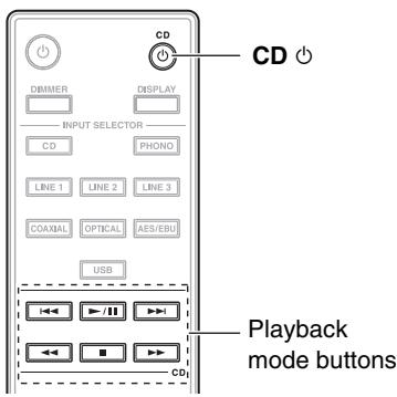
① CD ⏻ button
Used to set the compact disc player to On or Standby.
② Playback mode buttons
button
Used to select the previous song.
▶/11 button
Used to start or pause playback.
▶▶| button
Used to select the next song.
◀◀ button
Used to fast reverse the current song.
▶▶ button
Used to fast forward the current song.
■ button
Used to stop playback.
■ Controlling the Onkyo Dock ( 32)
③ Dock control buttons
SHUFFLE button
Used with the shuffle function.
MENU button
Opens iPod menu or returns to the previous menu.
REPEAT button
Used with the repeat function.
button
Used to select the previous song.
▶/II button
Used to start or pause playback.
▶▶| button
Used to select the next song.
Connections
Cable and Jacks
| Balanced AES/EBU |  |  | This is a professional digital audio interface. Balanced AES/EBU cables are used for better noise immunity and longer cable runs. The maximum sampling rate for PCM input is 192 kHz/24 bit, 2ch. | |
| USB digital audio | 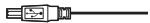 |  | USB digital connections allow you to enjoy digital sound. The preamplifier supports high-speed USB 2.0. Use Type A-B USB cable. The maximum sampling rate for PCM input is 192 kHz/32 bit, 2ch. | |
| Optical digital audio | 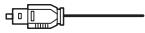 | [HKHO] | Optical digital connections allow you to enjoy digital sound such as PCM. The maximum sampling rate for PCM input is 96 kHz/24 bit, 2ch. Input and output jacks are provided. | |
| Coaxial digital audio | 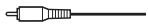 | [STTT] | Coaxial digital connections allow you to enjoy digital sound such as PCM. The maximum sampling rate for PCM input is 192 kHz/24 bit, 2ch. | |
| Analog audio (RCA) | 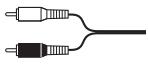 |  | Analog audio connections (RCA) carry analog audio. | |
| RI | 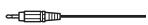 |  | To use RI (Remote Interactive), you must make an audio connection between the preamplifier and the Onkyo Dock. | |
| Mono mini-plug | 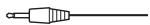 |  | Use the supplied or commercially available mono mini-plug cable to connect to the 12V trigger terminals on the other device for linked operation.The tip polarity of the connectors are as shown in the right. | 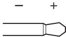 12 volts positive tip polarity 12 volts positive tip polarity |

Note
- Push plugs in all the way to make good connections (loose connections can cause noise or malfunctions).
- To prevent interference, keep audio cables away from power cords and speaker cables.
- The preamplifier's optical digital jacks have shutter-type covers that open when an optical plug is inserted and close when it's removed. Push plugs in all the way.
- To prevent shutter damage, hold the optical plug straight when inserting and removing.
- The analog audio cable can be used instead of the coaxial cable.
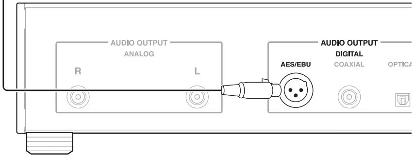
About Balanced Input (AES/EBU Jack)
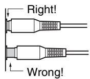
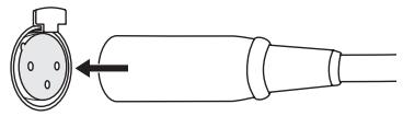
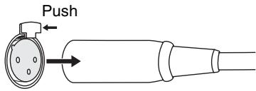
Plugging the AES/EBU cable
Match the pins and insert the terminal until you hear a “click.” Make sure that the terminal is locked by lightly pulling the connection cable.
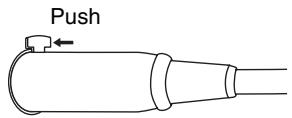
Unplugging the AES/EBU cable
Pull out the connection cable while holding down the lever.
1
2
1 Make sure that the main power of the preamplifier is turned off.
2 Connect all of your components.
3 Connect the supplied power cord to the preamplifier's AC INLET.
4 Plug the power cord into an AC wall outlet.
Q Tip
- To reduce noise, do not tie the signal cable and power cable together. Wire them so that they are away from each other.
Note
- Never disconnect the power cord from the preamplifier while the other end is still plugged into a wall outlet. Doing so may cause an electric shock. Always disconnect the power cord from the wall outlet first, and then the preamplifier.
- Turning on the preamplifier may cause a momentary power surge that might interfere with other electrical equipment on the same circuit. If this is a problem, plug the preamplifier into a different branch circuit.
- Do not use a power cord other than the one supplied with the preamplifier. The supplied power cord is designed exclusively for use with the preamplifier and should not be used with any other equipment.
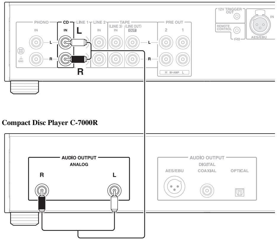
Connecting a Compact Disc Player
Analog Connection
Preamplifier P-3000R
Digital (Optical or Coaxial) Connection
Preamplifier P-3000R
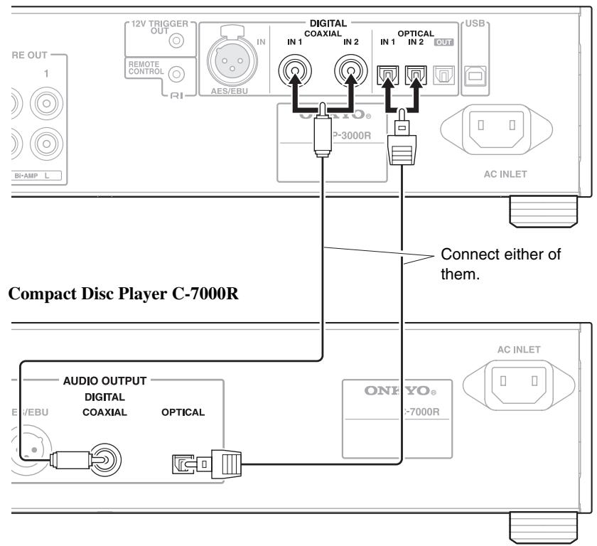
Preamplifier P-3000R
Compact Disc Player C-7000R
This is an example of the connection using the compact disc player C-7000R.
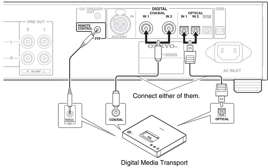
Connecting the Onkyo Dock
Preamplifier P-3000R
flowchart
graph TD
    A["PRE OUT 2 L R H BI-AMP L"] --> B["12V TRIGGER OUT"]
    B --> C["REMOTE CONTROL"]
    C --> D["RI"]
    D --> E["DIGITAL COAXIAL IN 1"]
    E --> F["OPTICAL IN 1 OUT"]
    F --> G["USB AC INLET"]
    G --> H["Connect either of them."]
    H --> I["OPTICAL"]
    I --> J["Digital Media Transport"]
    J --> K["COAXIAL"]
    K --> L["REMOTE CONTROL FI"]
    L --> M["AC INLET"]

Note
- You need to change the selector name to use RI function (→ 33).
- Use only RI cables for RI connections. RI cables are supplied with Onkyo Docks.
- Connect only Onkyo Dock to RI jacks. Connecting other manufacturer's components may cause a malfunction.
- Use only the Onkyo Dock with digital connections.
Connecting a Turntable
Preamplifier P-3000R
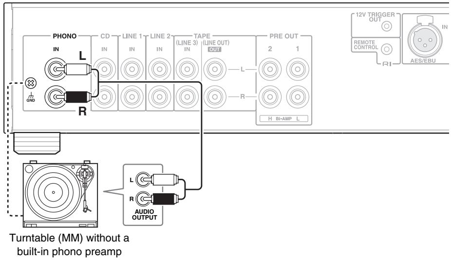
Remove the short pins plugged into the jacks before connecting a turntable to the PHONO inputs.
Q Tip
- If your turntable (MM) has a phono built-in preamp, you can connect to other analog inputs such as CD IN or LINE 1 IN.
- If your turntable has a moving coil (MC) type cartridge, you'll need a commercially available MC head amp or MC transformer to connect to PHONO IN. See your turntable's manual for details.
- If your turntable has a ground wire, connect it to GND screw. With some turntables, connecting the ground wire may produce an audible hum. If this happens, disconnect it.
Connecting a Cassette Tape Deck
Preamplifier P-3000R
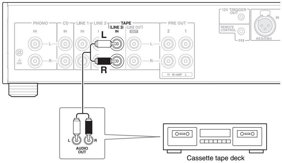
Connecting a Recording Component
Preamplifier P-3000R
Note
- Set “LINEOUT” setting to “RECOUT” (→ 34).
- When connecting a player recorder to TAPE IN (LINE 3 IN) and TAPE OUT (LINE OUT), always change the “LINEOUT” setting to the “RECOUT” ( 34).
Preamplifier P-3000R
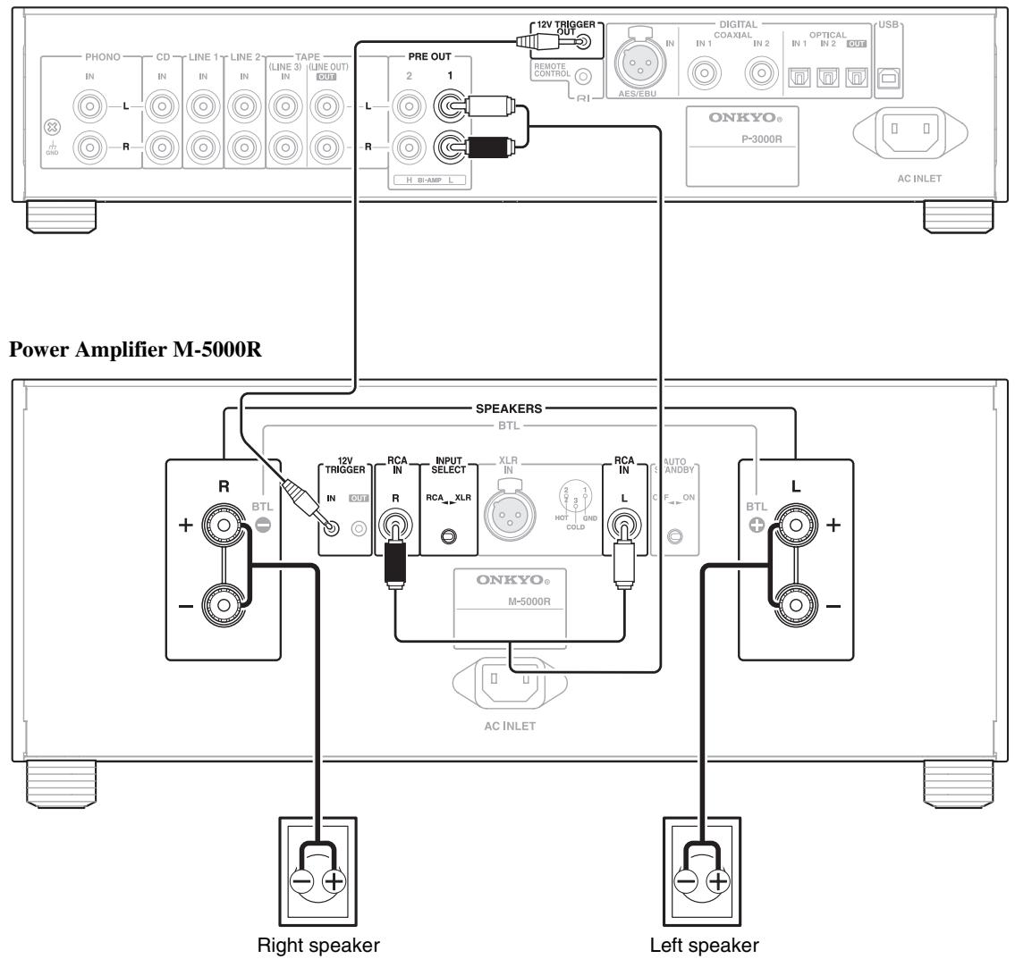
This is an example of the stereo connection using the power amplifier M-5000R.
flowchart
graph TD
    A["Preamplifier P-3000R"] --> B["Power Amplifier M-5000R"]
    A --> C["Power Amplifier M-5000R"]
    A --> D["Left speaker"]

    subgraph Preamplifier_P-3000R
        E["Phono IN"] --> F["L"]
        G["CD IN"] --> H["R"]
        I["LINE 1 IN"] --> J["L"]
        K["LINE 2 IN"] --> L["L"]
        M["TAPE (LINE 3) IN"] --> N["L"]
        O["LINE OUT OUT"] --> P
        P --> P
        P --> P
        P --> P
        P --> P
        P --> P
        P --> P
        P --> P
        P --> P
        P --> P
        P --> P
    end

    subgraph Power Amplifier_M-5000R
        Q["Speaker S"] --> R["BTL"]
        S["Speaker R"] --> T["AC INLET"]
        U["Speaker S"] --> V["Right speaker"]
        W["Speaker R"] --> X["Tweeter (high)"]
        Y["Speaker S"] --> Z["Woofer (low)"]
    end

    subgraph Left speaker
        AA["Speaker S"] --> AB["Tweeter (high)"]
        AC["Speaker R"] --> AD["Woofer (low)"]
    end

    E --> AE["12V TRIGGER OUT"]
    E --> AF["DIGITAL COAXIAL IN 1 IN 2 OPTICAL IN 1 OUT USB AES/EBU"]
    AF --> AG["USB"]

    subgraph Power Amplifier_M-5000R
        AH["Speaker S"] --> AI["BTL"]
        AJ["Speaker R"] --> AK["AC INLET"]
        AL["Speaker S"] --> AM["Right speaker"]
        AN["Speaker R"] --> AO["Tweeter (high)"]
        AP["Speaker S"] --> AQ["Woofer (low)"]
    end

    subgraph Left speaker
        AR["Speaker S"] --> AS["Tweeter (high)"]
        AT["Speaker R"] --> AU["Woofer (low)"]
    end
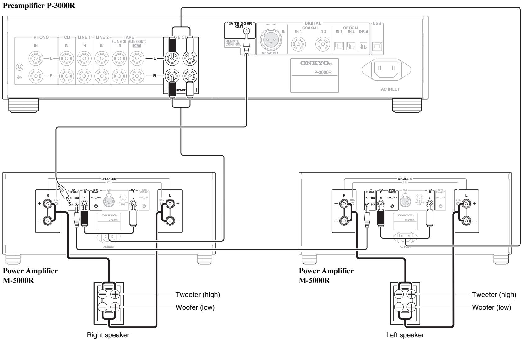
This is an example of the bi-amping connection using the power amplifier M-5000R.
Important:
- When making the bi-amping connections, be sure to remove the jumper bars that link the speakers' tweeter (high) and woofer (low) terminals.
- Bi-amping can be used only with speakers that support bi-amping. Refer to your speaker manual.
Preamplifier P-3000R
flowchart
graph TD
    A["Power Amplifier M-5000R"] --> B["Speaker"]
    A --> C["Analog audio input"]
    B --> D["AV receiver"]
    C --> D
    style A fill:#f9f,stroke:#333
    style B fill:#ccf,stroke:#333
    style C fill:#cfc,stroke:#333
    style D fill:#fcc,stroke:#333
    note1["■ Connecting an AV Receiver\nIf you connect analog audio to an AV receiver, the output will be stereo."] --> A
    note2["Connect either of them."] --> A
    note3["Right speaker"] --> B
    note4["Left speaker"] --> C
    note5["PROXED BY: ONKYO® M-5000R"] --> B
    note6["AC INLET"] --> B
    note7["REMOPE CONTROL"] --> B
    note8["PRE OUT"] --> B
    note9["H_BI-AMP"] --> B
    note10["R"] --> B
    note11["L"] --> B
    note12["R"] --> B
    note13["L"] --> B
    note14["R"] --> B
    note15["R"] --> B
    note16["R"] --> B
    note17["R"] --> B
    note18["R"] --> B
    note19["R"] --> B
    note20["R"] --> B
    note21["R"] --> B
    note22["R"] --> B
    note23["R"] --> B
    note24["R"] --> B
    note25["R"] --> B
    note26["R"] --> B
    note27["R"] --> B
    note28["R"] --> B
    note29["R"] --> B
    note30["R"] --> B
    note31["R"] --> B
    note32["R"] --> B
    note33["R"] --> B
    note34["R"] --> B
    note35["R"] --> B
    note36["R"] --> B
    note37["R"] --> B
    note38["R"] --> B
    note39["R"] --> B
    note40["R"] --> B
    note41["R"] --> B
    note42["R"] --> B
    note43["R"] --> B
    note44["R"] --> B
    note45["R"] --> B
    note46["R"] --> B
    note47["R"] --> B
    note48["R"] --> B
    note49["R"] --> B
    note50["R"] --> B
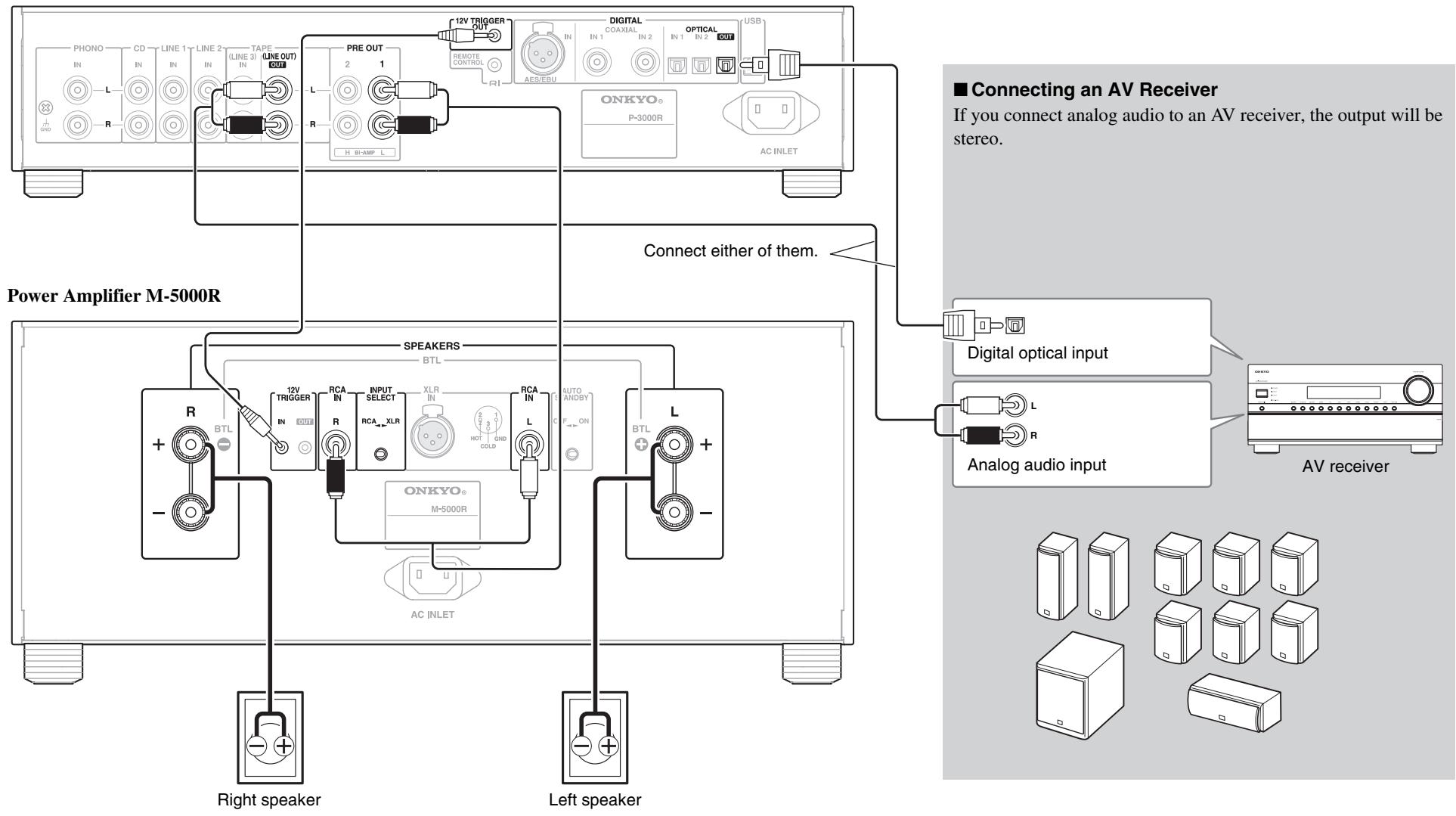
This is an example of the stereo connection using the power amplifier M-5000R.

Note
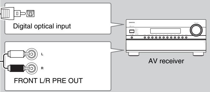
- If you make a digital audio connection between the preamplifier and AV receiver, analog input signal is not output from DIGITAL OUT.
Preamplifier P-3000R
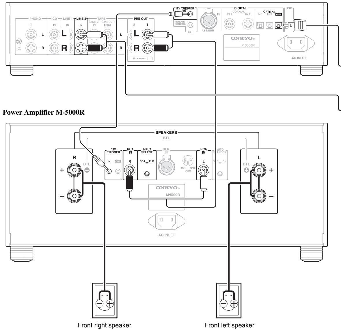

- To adjust the volume of the front speakers by the AV receiver, you must set the “L2 OUT” setting to “THROUGH” ( 35).
- When plugging other components such as compact disc players into the LINE 2 jack, change the “L2 OUT” setting to “NORMAL” (→ 35).
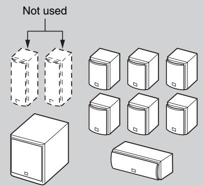
■ Surround sound system
flowchart
graph TD
    A["Digital optical input"] --> B["AV receiver"]
    C["FRONT L/R PRE OUT"] --> B
    style A fill:#f9f,stroke:#333
    style C fill:#ccf,stroke:#333
    style B fill:#dfd,stroke:#333
flowchart
graph TD
    A["Not used"] --> B["Storage Unit 1"]
    A --> C["Storage Unit 2"]
    B --> D["Storage Unit 3"]
    C --> E["Storage Unit 4"]
    D --> F["Storage Unit 5"]
    E --> G["Storage Unit 6"]
This is an example of the connection using the power amplifier M-5000R.
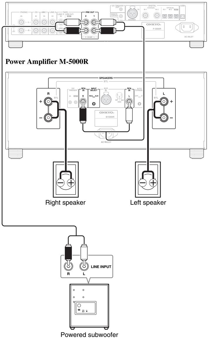
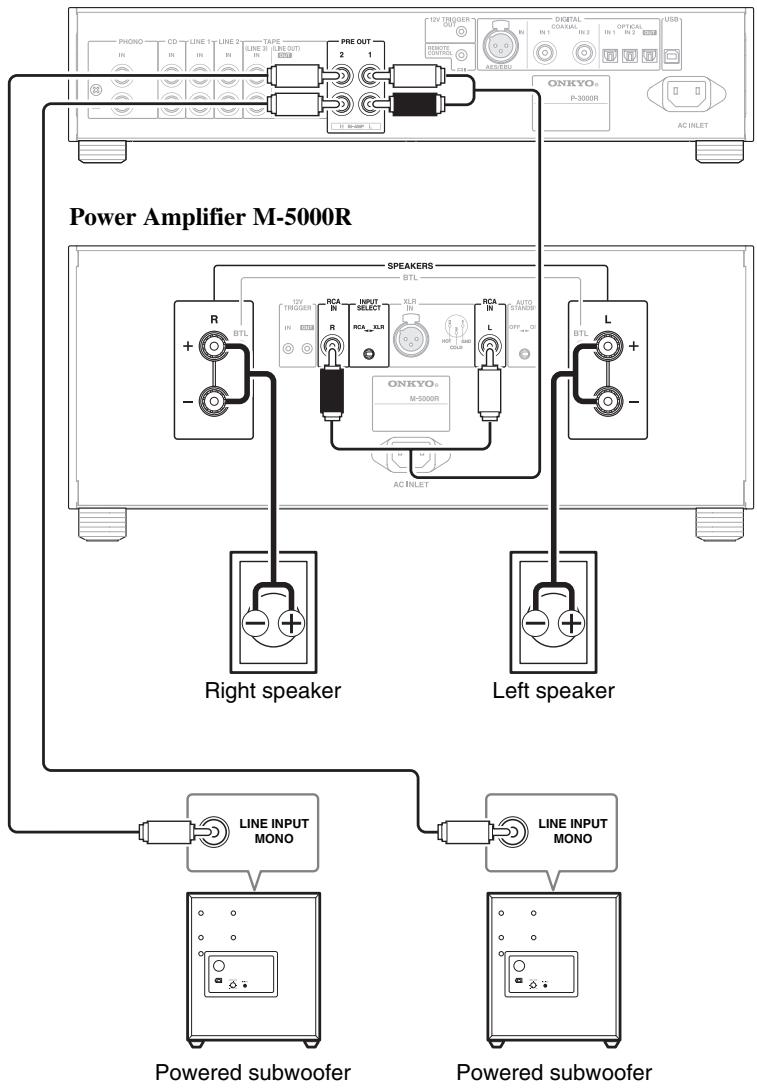
■ 2.1 channel system (2 speakers and 1 subwoofer)
Preamplifier P-3000R
flowchart
graph TD
    A["Power Amplifier M-5000R"] --> B["Right speaker"]
    A --> C["Left speaker"]
    A --> D["Powered subwoofer"]

    subgraph Power Amplifier M-5000R
        E["Phono IN"] --> F["R TBL"]
        G["CD IN"] --> H["+"]
        I["LINE 1 IN"] --> J["+"]
        K["LINE 2 IN"] --> L["+"]
        M["TAPE LINE B OUT"] --> N["+"]
        O["USB"] --> P["PRE OUT 2 1"]
        Q["ONKYO P-3000R"] --> R["AC INLET"]
        S["ONKYO M-5000R"] --> T["AC INLET"]
        U["SPEAKERS BTL"] --> V["12V TRIGGER IN"]
        W["RS"] --> X["IN"]
        Y["RS"] --> Z["+"]
        AA["RS"] --> AB["+"]
        AC["RS"] --> AD["+"]
        AE["RS"] --> AF["+"]
        AG["RS"] --> AH["+"]
        AI["RS"] --> AJ["+"]
        AK["RS"] --> AL["+"]
        AM["RS"] --> AN["+"]
        AO["RS"] --> AP["+"]
        AQ["RS"] --> AR["+"]
        AS["RS"] --> AT["+"]
        AU["RS"] --> AV["+"]
        AW["RS"] --> AX["+"]
        AY["AC INLET"] --> AZ["AC INLET"]
    end

    subgraph Left Speaker
        BA["BTL"] --> BB["L +"]
        BC["L +"] --> BD["-"]
        BE["BTL"] --> BF["L +"]
        BG["BTL"] --> BH["-"]
        BI["BTL"] --> BJ["-"]
    end

    subgraph Powered Subwoofer
        BK["R L LINE INPUT"] --> BL["Powered subwoofer"]
    end
This connection is not available for subwoofers that handle only mono input. A separate conversion cable is required.
■ 2.2 channel system (2 speakers and 2 subwoofers)
Preamplifier P-3000R
flowchart
graph TD
    A["Power Amplifier M-5000R"] --> B["Speaker 1: ONKYO₃ M-5000R"]
    A --> C["Speaker 2: RCAN IN R"]
    A --> D["Speaker 3: RCAN IN L"]
    A --> E["Speaker 4: RCAN IN IN R"]
    B --> F["Right speaker"]
    C --> G["Left speaker"]
    D --> H["Powered subwoofer"]
    E --> I["Powered subwoofer"]
    F --> J["Line INPUT MONO"]
    G --> K["Line INPUT MONO"]
    H --> L["Line INPUT MONO"]
    I --> M["Line INPUT MONO"]
Basic Operations
Turning On/Off the Preamplifier

Turning On the Preamplifier
1 Set POWER to the ON position (■) on the front panel.
2 Press ⏻ to turn on the preamplifier.
The preamplifier comes on, the display lights, and the Standby LED goes off.
You can also use preamplifier's ON/STANDBY.
Q Tip
- After a certain period of warming up, the temperature of the preamplifier's components and internal temperature are stabilized, and the sound will soften.
- The previous input source will appear on the display when the preamplifier turned on.
Note
- The preamplifier remembers the state when power was previously turned off, and returns to the state.
Turning Off the Preamplifier
1 Press ⏻ to set the preamplifier to Standby.
The preamplifier will enter Standby mode, and the Standby LED lights.
You can also use preamplifier's ON/STANDBY.
2 To completely shut down the preamplifier, set POWER to the OFF position (■).
Note
- See “Setting ASb (Auto Standby)” for the auto standby function ( 35).
Adjusting the Volume
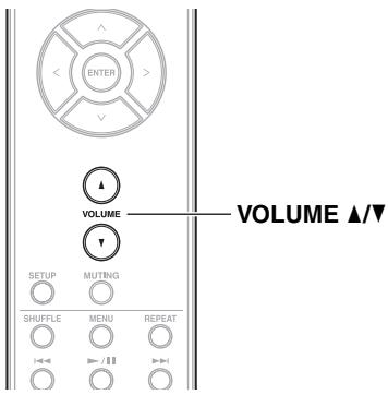
1 Use VOLUME ▲/▼ to adjust the volume.
You can also use preamplifier's volume controller.
Selecting the Input Source
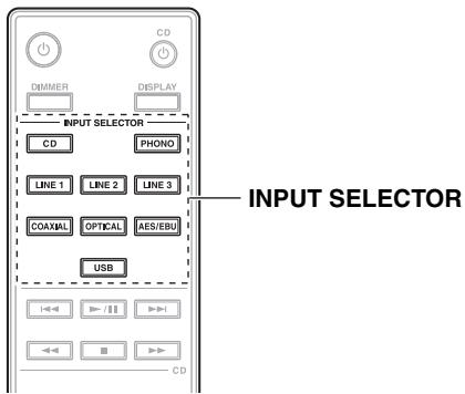
1 Use INPUT SELECTOR to select the input source. The COAXIAL and OPTICAL toggle every time they are pressed in the sequence of COAXIAL (COAX1 → COAX2) and OPTICAL (OPT1 → OPT2) respectively.
You can also use preamplifier's Multi jog dial to switch input sources in sequence.
The input sources are “CD”, “LINE 1”, “LINE 2”, “LINE 3”, “COAX1”, “COAX2”, “OPT1”, “OPT2”, “AES/EBU”, “USB”*, “PHONO”.
* You can select USB input only when the USB connector is connected.
Note
- When the USB connector is not connected, you cannot select USB even if you press USB on the remote controller. The message “NO USB” appears.
Hiding the Digital Source Display
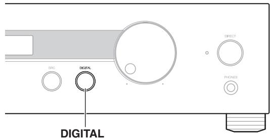
This setting makes the preamplifier not to display the digital sources.
1 Press DIGITAL repeatedly on the preamplifier.
▶ON (default):
Digital input sources are displayed.
▶ OFF:
Digital input sources cannot be selected.
The digital source display setting will be automatically switched from “OFF” to “ON”, if you press the digital input selector on the remote controller.
Note
- When digital input sources are selected, pressing DIGITAL has no effect.
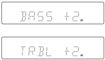
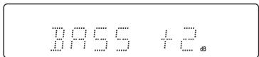
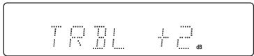
Adjusting the Bass, Treble and Balance

You can adjust the bass, treble and balance.
1 Press SETUP.
2 Press <//> to select “BASS”, “TREBLE” or “BALANCE”.
3 Press ENTER.
4 Press <//> to adjust the value.
The setting has been established.
BASS
TREBLE
The value changes by 2 dB and can be set from -8 dB to +8 dB.
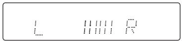
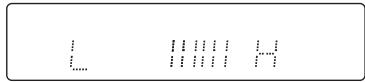
BALANCE
The left and right output balance can be adjusted.
To cancel the setup at any point, press SETUP.
You can also use preamplifier's MODE and Multi jog dial.
See “Using MODE button” to perform this procedure on the preamplifier ( 29).
Note
- The preamplifier will end the setup if there is no operation for 8 seconds.
- The tone controls are canceled when the Direct function is set to on.
Muting the Sound
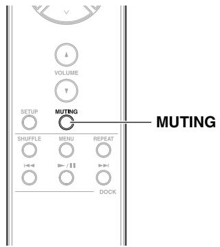
1 Press MUTING to mute the out of the preamplifier.
The MUTING indicator flashes on the display.
To unmute the preamplifier, press MUTING again.
Note
While preamplifier is muted:
- Turning the Volume controller on the preamplifier or pressing VOLUME ▲/▼ on the remote controller will unmute the preamplifier.
- If you turn the preamplifier off, the next time you turn it on, the preamplifier will be unmuted.
Using the Direct Function
1 Press DIRECT on the preamplifier to turn the Direct function on or off.
When the Direct function is off, the tone controls can be used to adjust the sound. When the Direct function is on, the tone controls are bypassed, so you can enjoy a pure sound, then front display goes off and the Direct LED lights.

Note
- The display lights for 5 seconds if you control anything else than volume or DIMMER on the front panel or remote controller when the display brightness is set to OFF.
Adjusting the Display Brightness
You can adjust the brightness of the preamplifier's display.
1 Press DIMMER repeatedly to change the brightness of the display in sequence.
Normal → Dim → Off
Normal
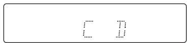
Dim
Off
The Display Off LED lights.


Note
- The display lights for 5 seconds if you control anything else than volume on the front panel or remote controller when the display brightness is set to OFF.
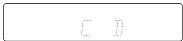
Changing the Display information
You can display the selected selector or the setting value.
1 Press DISPLAY to switch the display in sequence.
Selector

BASS
TREBLE
Input fs (sampling rate)
fs indicator
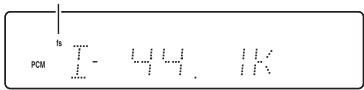
Output fs (sampling rate)

Note
- Input fs (sampling rate) and output fs (sampling rate) are displayed only while the DIGITAL selector is selected.
- Depending on the source, sometimes the value of the sampling rate differs from the actual display.
Using Headphones

1 Connect a pair of stereo headphones with a standard plug (1/4 inch or 6.3 mm) to the PHONES jack.
The Headphone indicator lights on the display.
You can adjust the volume and mute the sound, by using VOLUME ▲/▼.
While headphones are connected, the PRE OUT output no sound.

Note
- Always turn down the volume before connecting your headphones.
Using MODE button
Settings with SETUP of the remote controller can be also operated with the preamplifier.
1 Press MODE repeatedly to select the item.
2 Turn Multi jog dial to make a selection.
The setting has been established.

Note
- The preamplifier will end the setup if there is no operation for 8 seconds.
Playing the Onkyo Compact Disc Player
Playback
The Onkyo compact disc player connected to the preamplifier is played from its remote controller.

Note
- Make sure the remote controller is pointed at the compact disc player when using it.
- Depending on the component, you may not be able to control with the remote controller.
1 Press CD ⊙ to turn on the Onkyo compact disc player.
Used to set the compact disc player to On or Standby.
2 Press ▶/II.
The CD playback starts.
■ To Select Songs
Press ▶▶▶ to select the next song or ◀◀◀ to select the previous song.
■ To Fast-Forward or Fast-Reverse
During playback or while playback is paused, hold down ▶▶ to fast-forward or ◀◀ to fast-reverse.
For MP3/WMA CDs, fast-reverse only works within the MP3/WMA file that's currently playing.
■ To Pause Playback
During playback, press ▶/□ to pause playback. To resume playback, press ▶/□ again.
■ To Stop Playback
Press ■ to stop playback.
Playing Music Files on the PC
Connecting the PC
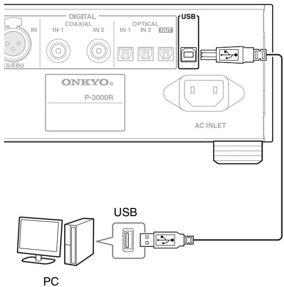
This section explains how to play music files on a PC through the preamplifier.
Installing a USB Driver
To playback the audio data stored on your PC by using the preamplifier via USB port connection, you must install the driver on your PC from the Onkyo website.
For the installation procedure, see the Onkyo Web site.
Playing Music Files on the PC
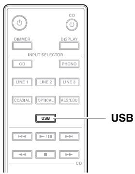
1 Press USB to switch the input to the USB selector.
You can also use preamplifier's Multi jog dial.
2 Play music files on the PC.

Note
- If you play incompatible file formats, then sound may not be output depending on the player software on the PC.
- If the sampling rate is greater than 96 kHz, no sound will come out of digital outputs.
- The USB selector on the display flashes if you unplug the USB cable.
- If the USB connector of your PC does not support the high-speed 2.0 standard, then audio is not output.
Using an Onkyo Dock
Playing Music Files on iPod
Connect an Onkyo Dock to the preamplifier, and play music files on iPod.
You can use the preamplifier's remote controller to control basic iPod functions and functionality depends on your iPod model and generation.
To control the Onkyo Dock with the preamplifier's remote controller, you need to switch the selector name ( 33).
■ To Start Playback
Press ▶/II or ENTER to start playback.
■ To Select a music file
Use ∧/∨ to select a music file.
■ To Select Songs
Press ▶▶▶▶ to select the next song or ◀◀◀▶ to select the last song.
■ To Pause Playback
During playback, press ▶/■ to pause playback.
To resume playback, press ▶/■ again.
■ To Use the menu
Press MENU to open iPod menu or return to the previous menu.
■ To Switch the Repeat Mode
Press REPEAT.
The repeat playback starts.
To cancel repeat playback, press REPEAT repeatedly.
■ To Switch the Shuffle Mode
Press SHUFFLE.
The shuffle playback starts.
To cancel shuffle playback, press SHUFFLE.
Onkyo Dock
Dock is sold separately. Use only the Onkyo Dock with digital connections.
For the latest information on the Onkyo Dock components, see the Onkyo web site at:
http://www.onkyo.com
Before using the Onkyo Dock components, update your iPod with the latest software, available from the Apple web site.
For supported iPod models, see the instruction manual of the Onkyo Dock.
■ System Function
Auto Power On
When you start playback on an Onkyo Dock while the preamplifier is on Standby, the preamplifier will automatically turn on and select an Onkyo Dock as the input source.
Direct Change
When playback is started on an Onkyo Dock, the preamplifier automatically selects an Onkyo Dock as the input source.
Remote Control
You can use the preamplifier's remote controller to control your Onkyo Dock, pointing the remote controller at the preamplifier's remote control sensor.
Q Tip
- If you use your iPod with any other accessories, iPod playback detection may not work.
- Use the preamplifier's volume control to adjust the playback volume.
- While your iPod is inserted in an Onkyo Dock, its volume control has no effect.
Note
- When the set ASb starts running, the power of the Onkyo Dock connected via RI is automatically turned off ( 35) .
Apple and iPod are trademarks of Apple Inc., registered in the U.S. and other countries.
Custom Setup
Changing the Selector Name
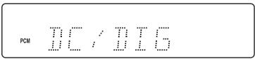
You can switch the selector name to DC/DIG to run as the DOCK selector.
1 Select the Digital input source (COAX1, COAX2, OPT1, OPT2) to change the selector name.
2 Press DISPLAY for 3 seconds.
“DC/DIG” is displayed on the display.
■ To cancel the assignment
Press DISPLAY again for 3 seconds.

- DOCK can be selected for the Digital input source (COAX1, COAX2, OPT1, OPT2) input selector, but not at the same time.
Selecting the Sampling Rate Conversion
You can convert the sampling rate of the input digital signal.
1 Press SRC repeatedly on the preamplifier.
▶ BYPASS (default):
Outputs the input sampling rate at the original sampling rate.
▶ FS x2:
Outputs the input sampling rate by converting it to x2.
▶ FS x4:
Outputs the input sampling rate by converting it to x4.
Note
- If the sampling rate is greater than 192/176.4 kHz, the sampling rate conversion will not be applied.
- Only analog audio is output by converting sampling rates. No digital audio is reproduced.
- To confirm the current setting value, see “Changing the Display information” (→ 28).
- Digital input signals are put through and output on this preamplifier as is.
- The USB input does not support FS x4 (→ 31).
Setting the Bi-amp Level

Offset the volume level based on master volume.
1 Press SETUP.
2 Press <//> to select "BIAMP".
3 Press ENTER.
4 Press </> to adjust the bi-amp level.
The high and low output balance can be adjusted.
The setting has been established.
You can also use preamplifier's MODE and Multi jog dial. See “Using MODE button” to perform this procedure on the preamplifier ( 29).
Note
- The preamplifier will end the setup if there is no operation for 8 seconds.
Setting the Headphone Level

You can set the volume when using headphones.
1 Press SETUP.
2 Press <//> to select "HPLEVEL".
3 Press ENTER.
4 Press <//> to adjust the volume level. The setting has been established.
You can also use preamplifier's MODE and Multi jog dial. See “Using MODE button” to perform this procedure on the preamplifier ( 29).

- When using the headphones, the balance setting will not be applied.
- The preamplifier will end the setup if there is no operation for 8 seconds.
Selecting the Analog Audio Out
The TAPE OUT (LINE OUT) jack can produce audio output by connecting the cassette tape deck with the preamplifier.
1 Press SETUP.
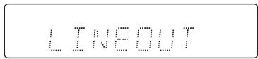
2 Press <//> to select "LINEOUT".
3 Press ENTER.
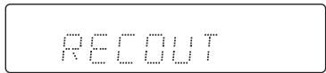
4 Press <//> to switch between "LINEOUT" and "RECOUT".
LINEOUT (LINE 3)
Outputs any signal from the input selector.
▶ RECOUT (TAPE)
The selector name becomes TAPE. Signals input from LINE 3 IN will not be output from LINE OUT.
5 Press ENTER.
“FINISH” appears on the display.
You can also use preamplifier's MODE and Multi jog dial.
See “Using MODE button” to perform this procedure on the preamplifier ( 29).
Q Tip
Usage example of RECOUT:
- Perform recording by connecting the turntable to P-3000R (PHONO IN jack), and the cassette tape deck to LINE 3 (IN/OUT jack) of P-3000R.
Note
- The preamplifier will cancel the setup if there is no operation for 8 seconds.
- When connecting a component such as a cassette tape deck, change the “LINEOUT” setting to “RECOUT” for anti-vibration purpose.
Setting ASb (Auto Standby)

When ASb is turned on, the preamplifier will automatically enter Standby mode if there is no operation for 30 minutes with no audio signal input.
1 Press SETUP.
2 Press <//> to select "ASb".
3 Press ENTER.
4 Press <//> to switch between "ASb ON" and "ASb OFF".
▶ ASb ON:
ASb enabled.
▶ ASb OFF:
ASb disabled.
Default setting: ASb ON (European models),
ASb OFF (North American models)
5 Press ENTER.
“FINISH” appears on the display.
You can also use preamplifier's MODE and Multi jog dial. See “Using MODE button” to perform this procedure on the preamplifier ( 29).
Once the ASb function has been activated, the preamplifier will not automatically turn on even if it receives the signal. To turn on the preamplifier, press ON/STANDBY manually.
Note
- When the set ASb starts running, the power of the Onkyo Dock connected via RI is automatically turned off (→ 32).
- The preamplifier will cancel the setup if there is no operation for 8 seconds.
- Before entering standby mode with the ASb function, the Display Off LED flashes 30 seconds before the ASb function starts running.
LINE 2 Output with a Fixed Volume
Switch L2 OUT to enable the volume adjustment from another component connected to the preamplifier.
1 Press SETUP.
2 Press <//> to select "L2 OUT".
3 Press ENTER.
4 Press to switch between "NORMAL" and "THROUGH".
NORMAL:
You can adjust the PRE OUT volume by the preamplifier's volume controller when the signal coming from the LINE 2 IN is output from the PRE OUT.
THROUGH:
The PRE OUT output of the preamplifier is fixed.
5 Press ENTER.
“FINISH” appears on the display.
You can also use preamplifier's MODE and Multi jog dial. See “Using MODE button” to perform this procedure on the preamplifier ( 29).
Note
- The preamplifier will cancel the setup if there is no operation for 8 seconds.
- To check the connection in which this setting is enabled, see “Using Stereo Speakers as the Front Speakers for Your Surround Sound System” ( 23).
- When plugging other components such as compact disc players into the LINE 2 jack, change the “L2 OUT” setting to “NORMAL”.
Troubleshooting
If you have any trouble using the preamplifier, look for a solution in this section.
■ How to reset to factory default?
- After setting the volume higher than the minimum level, press ON/STANDBY while holding down MODE on the preamplifier.
- “CLEAR” appears on the display, then the preamplifier will automatically go Standby. Do not operate the preamplifier while “CLEAR” is displayed.
Note that resetting the preamplifier will delete your custom settings.
Power
Can't turn on the Preamplifier.
- Make sure that the power cord is properly plugged into the wall outlet ( 16) .
- Unplug the power cord from the wall outlet, wait 5 seconds or more, then plug it in again.
The Preamplifier turns off unexpectedly.
- When the set ASb starts running, the preamplifier will automatically go Standby (→ 35).
Audio
There's no sound.
- Make sure the preamplifier's volume control is not set to minimum ( 26) .
- Make sure the correct input source is selected (→ 26).
- Make sure the preamplifier is not muted ( 27).
- Make sure the speakers are connected correctly ( 15).
- Check all connections and correct as necessary ( 15).
- While headphones are connected, the PRE OUT output no sound ( 29).
- The preamplifier does not support digital formats other than PCM. Inputting a digital format other than PCM will cause loud noise.
- If the USB connector of your PC does not support the high-speed 2.0 standard, then audio is not output.
- Make sure the POWER switch is set to ON.
The sound quality is not good.
- Make sure all audio connecting plugs are pushed in all the way ( 15) .
- The sound quality can be affected by strong magnetic fields, such as that from a TV. Try moving any such devices away from the preamplifier.
- If you have any devices that emit high-intensity radio waves near the preamplifier, such as a cellular phone that's being used to make a call, the preamplifier may output noise.
Headphone output is intermittent or there's no sound.
- This may be due to dirty contacts. Clean the headphones plug. See your headphones' instruction manual for cleaning information. Also, make sure that the headphones cable is not broken or damaged.
Audio performance
- Audio performance will be at its best about 10 to 30 minutes after the preamplifier has been turned on and had time to warm up.
- Using cable ties to bundle audio cables with speaker or power cables may degrade the sound quality. So don't do it.
The volume adjustment of LINE 2 does not work
- Lower the volume of the connected AV receiver, and release “THROUGH” of “L2 OUT” of the preamplifier ( 35).
PC Playback
Can't playing the music files on the PC.
- Make sure that the USB cable is plugged in firmly ( 15) .
- Make sure that the USB driver is installed successfully ( 31) .
Can't display the sampling rate correctly.
- Make sure that there is no unsupported file formats or signals.
The USB selector on the display flashes.
- The USB cable is unplugged. To stop the blinking of the display, turn the power ON/OFF, or plug the USB cable again.
Onkyo Dock
There's no sound.
- Make sure that the Onkyo Dock is connected to the preamplifier properly.
- Make sure that no video content is being played.
- Reset the iPod.
Other
- When the set ASb starts running, the power of the Onkyo Dock connected via RI is automatically turned off ( 35) .
Can't control properly by using the remote controller.
- Make sure that the RI cable is connected to the preamplifier correctly.
You need to change the selector name to use RI function ( 33).
External Components
No sound is heard from a connected component.
- Make sure the correct input source is selected ( 26) .
- Make sure the analog audio cable is connected correctly ( 15) .
The sound from record player is distorted.
- If your turntable (MM) has a phono built-in preamp, connect to other analog inputs such as CD IN or LINE 1 IN.
- If your turntable (MM) does not have a phono built-in preamp, connect a turntable (MM) without a built-in a phono preamp to PHONO IN ( 19) .
- Make sure that the ground wire is connected. Otherwise, it may produce an audible hum and noise.
A popping noise is produced when the power is set to ON or OFF.
- Turn each of the components' power on or off in the following order.
When turning the power on:
- Source component
- Preamplifier (P-3000R)
- Power Amplifier (M-5000R ^* )
When turning the power off:
- Power Amplifier (M-5000R ^* )
- Preamplifier (P-3000R)
- Source component
* When using 12V TRIGGER OUT as M-5000R is combined with P-3000R, the popping noise is reduced by power management.
Remote Controller
The remote controller doesn't work properly.
- Make sure the batteries have been installed with the correct polarity (+/-) (→ 10).
- Replace both batteries with new ones. (Do not mix different types of batteries or new and old batteries.)
- The remote controller is too far away from the preamplifier, or there's an obstacle between them ( 10) .
- The preamplifier's remote control sensor is being subjected to bright light (inverter-type fluorescent light or sunlight).
- The preamplifier is located behind the glass doors of a audio rack or cabinet.
Onkyo is not responsible for damages (such as CD rental fees) due to unsuccessful recordings caused by the unit's malfunction. Before you record important data, make sure that the material will be recorded correctly.
The preamplifier contains a microcomputer for signal processing and control functions. In very rare situations, severe interference, noise from an external source, or static electricity may cause it to lockup. In the unlikely event that this should happen, unplug the power cord, wait at least 5 seconds, and then plug it again.
Before disconnecting the power cord from the wall outlet, set the preamplifier to Standby.
Specifications
P-3000R
| THD+N (Total Harmonic Distortion+Noise) | 0.005 % (20 Hz - 20 kHz, Power Rated) |
| Input Sensitivity and Impedance (Unbalance) | 200 mV/47 kΩ (LINE)2.7 mV/47 kΩ (PHONO MM) |
| Rated RCA Output Level and Impedance | 1 V/330 Ω (PRE OUT) |
| Maximum RCA Output Level and Impedance | 5.0 V/ 330 Ω (PRE OUT) |
| Phono Overload | 80 mV (MM 1 kHz 0.5 %) |
| Frequency Response | 5 Hz-100 kHz/+0, -3 dB (LINE) |
| Tone Control Characteristics | ±8 dB, 50 Hz (BASS)±8 dB, 20 kHz (TREBLE) |
| Signal to Noise Ratio | 110 dB (Direct, IHF-A)80 dB (PHONO, IHF-A) |
| Power Supply | (North American)AC 120 V, 60 Hz(European) AC 230 V, 50 Hz |
| Power Consumption | (North American) 26 W(European) 29 W |
| Standby Power Consumption | (North American) 0.2 W(European) 0.3 W |
| Dimensions (W × H × D) | 435 W × 99 H × 333.1 D mm(17-1/8" W × 3-7/8" H × 13-1/8" D inches) |
| Weight | 11.0 kg (24.3 lbs.) |
■ Audio Inputs
| Digital Inputs | Optical: 2Coaxial: 22ch PCMDigital Input Sampling Rate:32 kHz/44.1 kHz/48 kHz/88.2 kHz/96 kHz compatible (OPT)32 kHz/44.1 kHz/48 kHz/88.2 kHz/96 kHz/176.4 kHz/192 kHz compatible(COAX, AES/EBU)44.1 kHz/48 kHz/96 kHz/192 kHz compatible(USB) |
| Analog Stereo Inputs | PHONO, CD, LINE 1, LINE 2, TAPE (LINE 3) |
| Balance Inputs | AES/EBU (DIGITAL) |
■ Audio Outputs
| Digital Outputs | Optical: 1Digital Output Sampling Rate:32 kHz/44.1 kHz/48 kHz/88.2 kHz/96 kHz compatible (OPT) |
| Analog Stereo Outputs | TAPE (LINE) |
| Pre Outputs | 2 |
| Phones | 1 (6.3 ) |
Others
| 12V Trigger Out | 1 |
| RI | 1 |
| PC Interface | USB |
■ System Requirements
| USB | 1 |
| OS | Windows® 7 (32 bits/64 bits)/Windows Vista®(32/64 bits)/Windows® XP (32/64 bits) SP3 or later |
| CPU | Intel® Pentium® 4 processor 1.6 GHz or higher processor |
| RAM | 512 MB or greater |
| HDD | 60 MB or greater free hard drive space |
| Supported models | PC/AT compatible machine equipped with a USB port compliant with the USB standard Rev2.0 HS (Intel® USB host controller is recommended) |
Specifications and features are subject to change without notice.
Windows and the Windows logo are trademarks of the Microsoft group of companies.
Memo
ONKYO®
18 Park Way, Upper Saddle River, N.J. 07458, U.S.A.
Tel: 800-229-1687, 201-785-2600 Fax: 201-785-2650
http://www.us.onkyo.com/
ONKYO EUROPE ELECTRONICS GmbH
Liegnitzerstrasse 6, 82194 Groebenzell, GERMANY
Tel: +49-8142-4401-0 Fax: +49-8142-4401-555
http://www.eu.onkyo.com/
ONKYO EUROPE ELECTRONICS GmbH (UK BRANCH)
The Coach House 81A High Street, Marlow, Buckinghamshire, SL7 1AB, UK
Tel: +44-(0)1628-473-350 Fax: +44-(0)1628-401-700
ONKYO CHINA LIMITED
Unit 1 & 12, 9/F, Ever Gain Plaza Tower 1, 88, Container Port Road, Kwai Chung,
N.T., Hong Kong. Tel: 852-2429-3118 Fax: 852-2428-9039
http://www.ch.onkyo.com/
ONKYO CHINA PRC
1301, 555 Tower, No.555 West NanJin Road, Jin an, Shanghai,
China 200041, Tel: 86-21-52131366 Fax: 86-21-52130396