
DHP-302 - Powerline Adapter D-LINK - Free user manual and instructions
Find the device manual for free DHP-302 D-LINK in PDF.
| Product Type | CPL Adapter (Powerline) |
| Brand | D-Link |
| Model | DHP-302 |
| Supported Standard | HomePlug AV |
| Maximum Speed | Up to 200 Mbps |
| Ports | 1 Ethernet RJ-45 10/100 port |
| Integrated Power Socket | No (direct plug) |
| Power Supply | 100-240 V AC, 50/60 Hz |
| Power Consumption | ~3 W operating |
| Dimensions (L x W x H) | 8.0 x 5.5 x 3.5 cm |
| Weight | ~95 g |
| Operating Temperature | 0 °C to 40 °C |
| Operating Humidity | 10% to 85% non-condensing |
| Security | AES 128-bit encryption |
| Pairing Button | Yes (pairing) |
| Main Functions | Network transmission via powerline, wired network extension |
| Care and Cleaning | Clean with a soft, dry cloth. Do not use liquid products. |
| Spare Parts and Repairability | Not available. Device not user-serviceable. |
| Package Contents | 2 powerline adapters, Ethernet cables, quick installation guide |
Frequently Asked Questions - DHP-302 D-LINK
User questions about DHP-302 D-LINK
0 question about this device. Answer the ones you know or ask your own.
Ask a new question about this device
Download the instructions for your Powerline Adapter in PDF format for free! Find your manual DHP-302 - D-LINK and take your electronic device back in hand. On this page are published all the documents necessary for the use of your device. DHP-302 by D-LINK.
USER MANUAL DHP-302 D-LINK
natural_image
White D-Link DHP-302 device with circular control panel and ventilation grille (no visible text or symbols on body)Table of Contents
Product Overview....3
Package Contents .... 3
System Requirements .... 3
Introduction....4
Features 4
Hardware Overview 5
LEDs 5
Connection....6
Hardware Installation 7
Push Button Security 8
Using the Setup Wizard 11
Configuration....13
Setup 15
Security....17
Application QoS....18
Advanced QoS 19
System....20
Troubleshooting 21
Technical Specifications....22
Package Contents
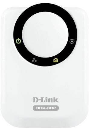
• D-Link DHP-302 Powerline HD Ethernet Adapter
- CAT5 Ethernet Cable
• CD-ROM with Software and Manual
- Quick Installation Guide
natural_image
White D-Link DHP-30e device with control knob and ports (no visible text beyond branding)System Requirements
- Windows Vista®, XP (with Service Pack 2) or 2000 (with Service Pack 4)
• PC with 233MHz Processor, 64MB Memory - Ethernet Adapter (100MBit/s)
Introduction
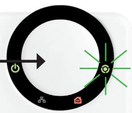
D-Link announces a fast, 200Mbps Powerline HD Ethernet Adapter which allows you to network your home computers, networking devices and gaming devices through the most pervasive medium in your house - the electric powerlines - and share Internet connections, printers, transfer files, play games, and more. This kit can be used to network two Ethernet-enabled devices with a 10/100Base-T adapter through powerlines.
Features
- Provides Ethernet to Powerline Connection
- Fast Data Transfer Rate of Up to 200Mbps
• One 10/100 Ethernet port - Plug & Play, Easy Installation
- Easy to use Management Software
- Configurable QoS for video streaming, VoIP and Gaming
- Firmware Upgrade Support
- Push button security
- Throughput LED
• Power Saving mode - LLTD Support (Windows Vista®)
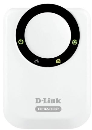
Hardware Overview LEDs
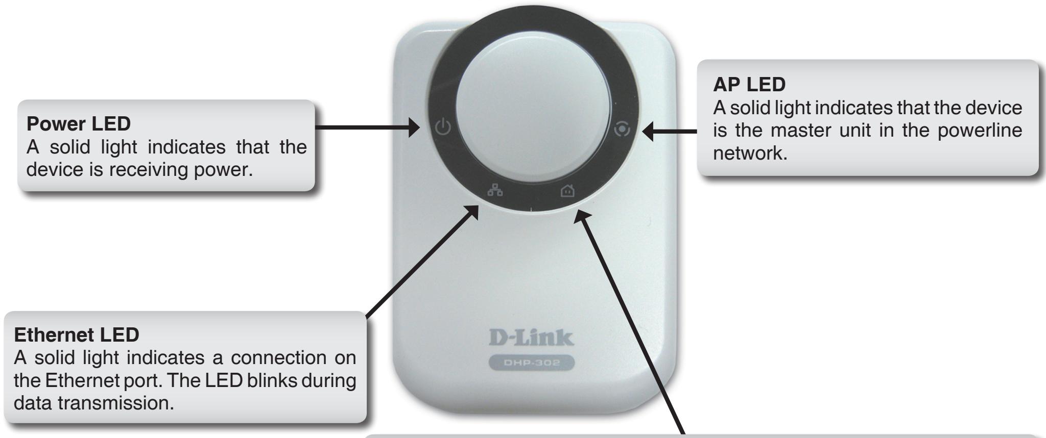
Throughput LED
A solid green light indicates that the master device has detected another Powerline device on the network.
Green LED: Power Line speed > 20Mbps (non master unit)
Amber LED: Power Line speed < 20Mbps or > 6Mbps (non master unit)
Red LED: Power Line speed < 6Mbps or link is down. (non master unit)
Hardware Overview Connection
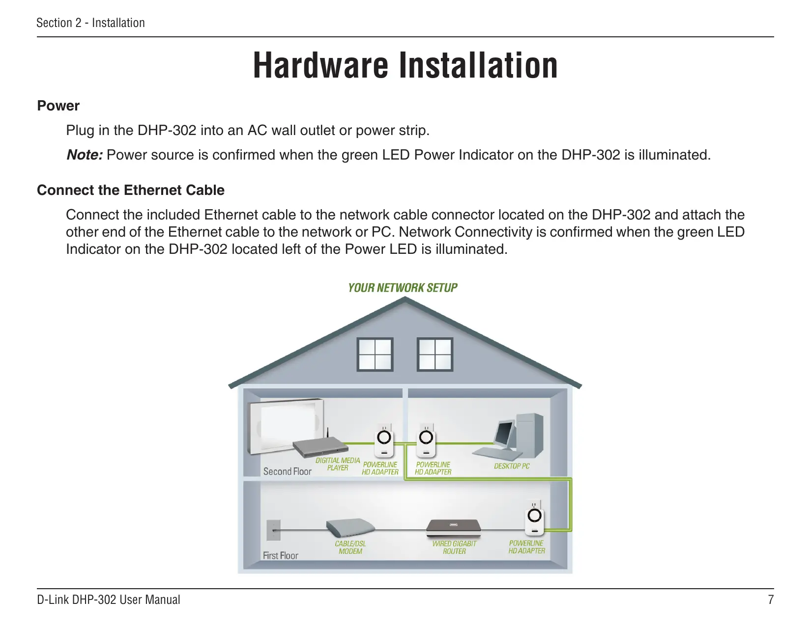
Hardware Installation
Power
Plug in the DHP-302 into an AC wall outlet or power strip.
Note: Power source is confirmed when the green LED Power Indicator on the DHP-302 is illuminated.
Connect the Ethernet Cable
Connect the included Ethernet cable to the network cable connector located on the DHP-302 and attach the other end of the Ethernet cable to the network or PC. Network Connectivity is confirmed when the green LED Indicator on the DHP-302 located left of the Power LED is illuminated.
flowchart
graph TD
    A["First Floor"] --> B["CABLE/DSL MODEM"]
    B --> C["WIRED GIGABIT ROUTER"]
    C --> D["POWERLINE HD ADAPTER"]
    D --> E["POWERLINE HD ADAPTER"]
    E --> F["DESKTOP PC"]
    F --> G["Digital Media Player"]
    G --> H["Second Floor"]
    style A fill:#ccc,stroke:#333
    style B fill:#ccc,stroke:#333
    style C fill:#ccc,stroke:#333
    style D fill:#ccc,stroke:#333
    style E fill:#ccc,stroke:#333
    style F fill:#ccc,stroke:#333
    style G fill:#ccc,stroke:#333
    style H fill:#ccc,stroke:#333
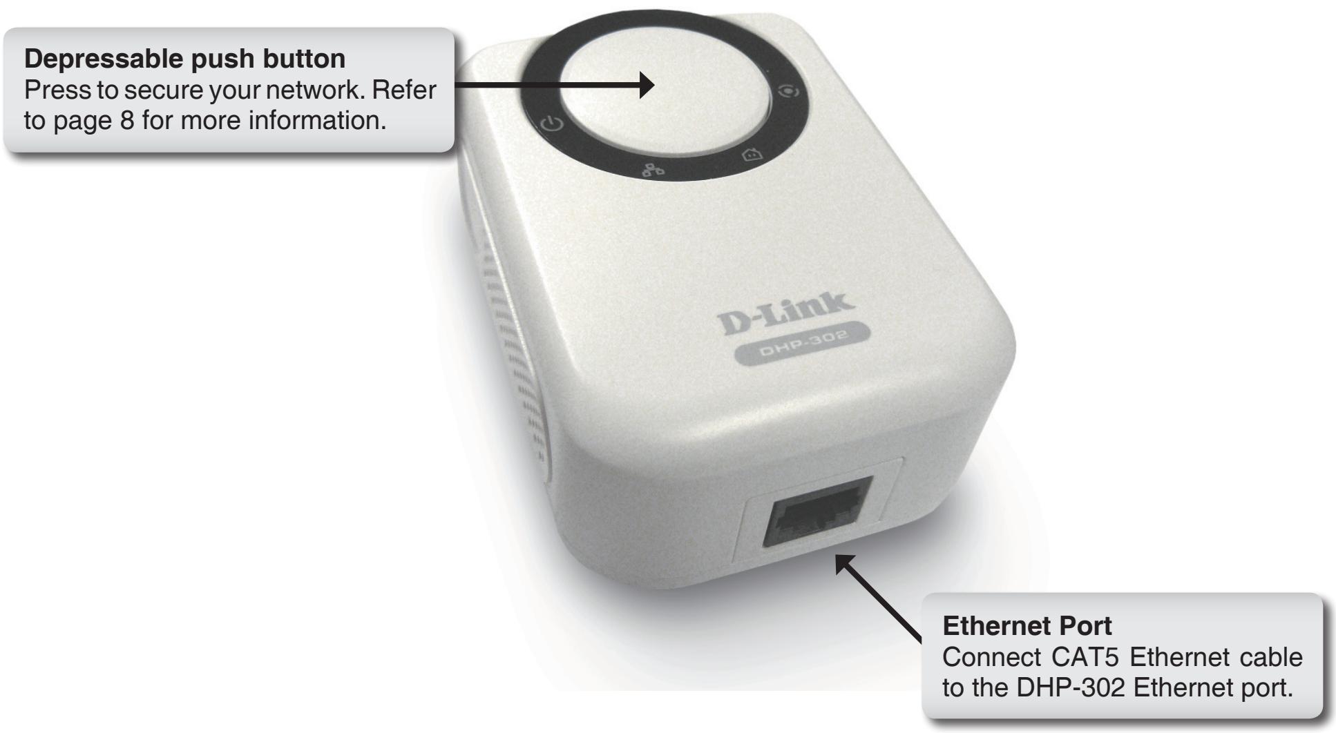
Push Button Security
Plug in all the adapters to be configured.
Note: It is strongly recommended to designate the local adapter as the one that is directly connected to your router. This local adapter will act as the security key master in the network. Each additional adapter you proceed to add afterwards will be referred to as a 'remote' adapter.
Local adapter
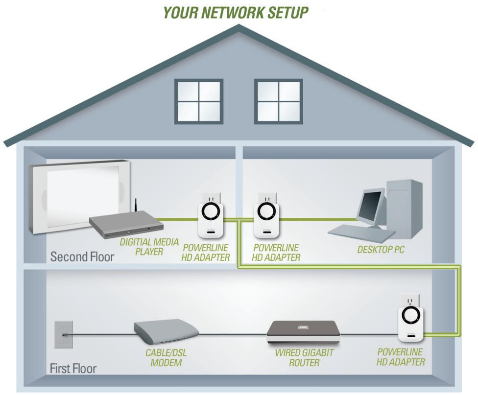
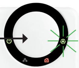
Press and hold the push button down until the local adapter AP LED begins to flash. Wait until the AP LED stops flashing (up to 30 seconds). At this point the local adapter is now assigned as the master adapter in your network.
Press and hold the button
flowchart
graph TD
    A["Power"] --> B["Arrow"]
    B --> C["Green Starburst"]
    C --> D["Central Node"]
    D --> E["Green Marker"]
    E --> F["Home Icon"]
    style A fill:#000,stroke:#fff,color:#fff
    style B fill:#000,stroke:#fff,color:#fff
    style C fill:#000,stroke:#fff,color:#fff
    style D fill:#000,stroke:#fff,color:#fff
    style E fill:#000,stroke:#fff,color:#fff
    style F fill:#000,stroke:#fff,color:#fff
D-Link
DHP-302
natural_image
Circular black ring with small icons (power, battery, factory) on each side, no text or symbols present.D-Link
DHP-302
To proceed securing the remote adapters follow the 3-step process below
Local Adapter
Local Adapter
1. Local adapter
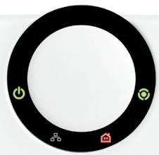
Begin by pressing the push button until its AP LED starts to flash. During this flashing phase the adapter is actively waiting for other adapters to sync
Press and hold the button
natural_image
Circular diagram with directional arrows and icons (no text or labels)2. Remote (additional) adapters
Push the button on the remote adapter until the AP LED begins flashing. (It is important to ensure the local adapter AP LED is still in the flashing state while you do this).
Press and hold the button
flowchart
graph TD
    A["Start"] --> B{Decision}
    B -->|Yes| C["Process Step"]
    B -->|No| D["End"]
After a few seconds, successful synchronization should occur. This is visible when the remote adapter's AP LED switches off indicating that it is securely configured. The local adapter AP LED however, will continue to remain solidly lit and the throughput LED should turn Green.
natural_image
White D-Link device with black circular ring and control icons, labeled DHP-302 (no readable text beyond branding)Remote Adapter
natural_image
White D-Link device with black ring and control buttons, labeled DHP-302 (no readable text beyond branding)Local Adapter
Note: When adding more adapters, repeat steps 1 to 3. At the end of this process, only the local adapter should have the AP LED lit.
Also, the adapters will keep their security settings even after the power is removed from the units. To reset / switch-off any adapter security back to default: Depress and hold (up to 15 seconds) the push button until the AP LED turns off. This will reset the unit back to the factory default settings
Using the Setup Wizard
Follow the simple steps below to run the Setup Wizard to guide you quickly through the installation process.
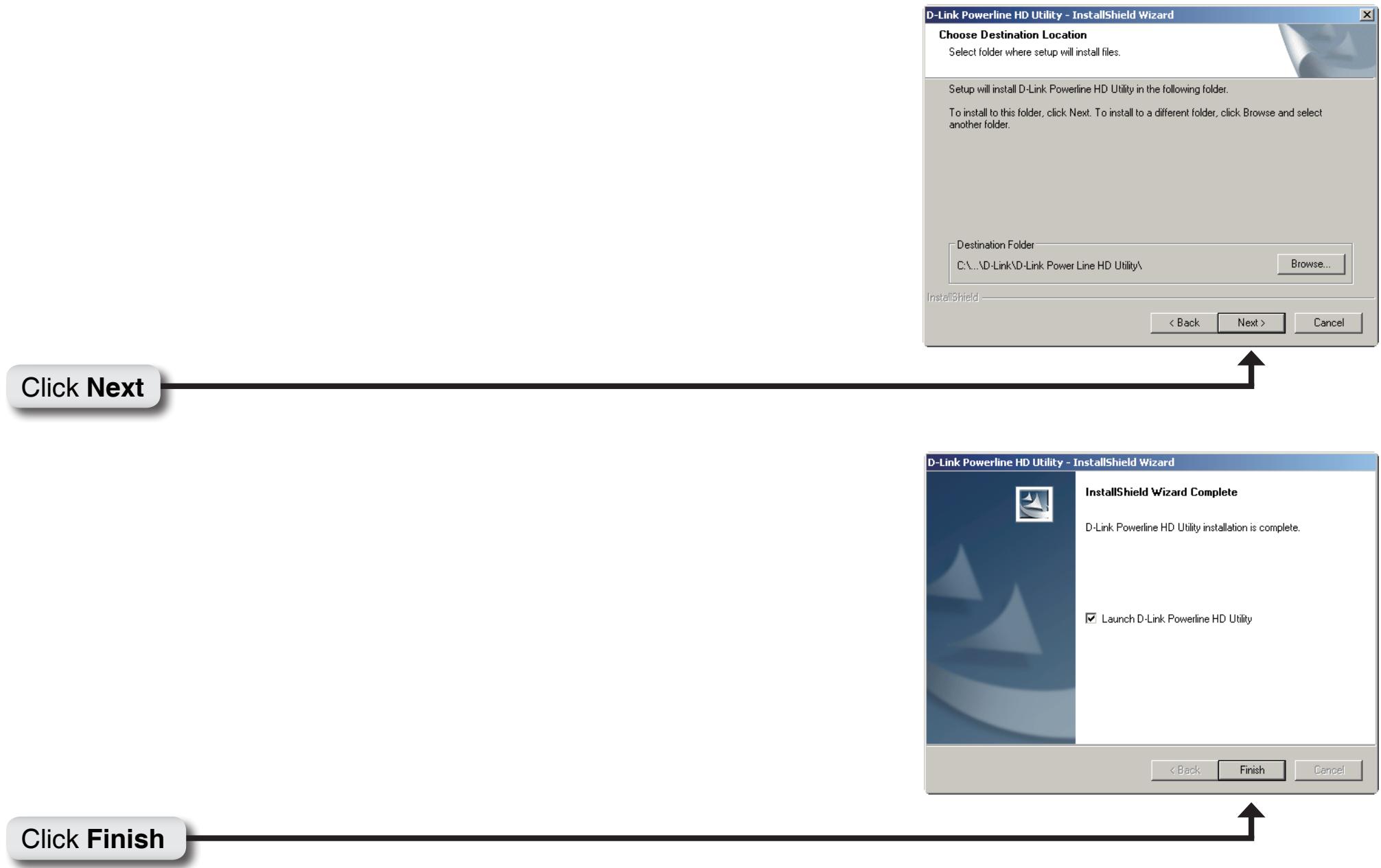
Insert the D-Link DHP-302 CD into your CD-ROM drive. If the CD Autorun function does not automatically start on your computer, click Start > Run.
In the Run command box type "D:\DHP302.exe", where D: represents the drive letter of your CD-ROM. If it does start, proceed to the next screen.
Click on Install Utility
The InstallShield Wizard will begin the DHP-302 software installation.

Click Next
flowchart
graph TD
    A["Click Next"] --> B["D-Link Powerline HD Utility - InstallShield Wizard"]
    B --> C["Choose Destination Location\nSelect folder where setup will install files."]
    C --> D["Setup will install D-Link Powerline HD Utility in the following folder.\nTo install to this folder, click Next. To install to a different folder, click Browse and select another folder."]
    D --> E["Destination Folder\nC:\...\D-Link\D-Link Power Line HD Utility\ Browse..."]
    E --> F["InstallShield"]
    F --> G["< Back"]
    F --> H["Next >"]
    F --> I["Cancel"]
    J["Click Finish"] --> K["D-Link Powerline HD Utility - InstallShield Wizard"]
    K --> L["InstallShield Wizard Complete\nD-Link Powerline HD Utility installation is complete."]
    L --> M["Launch D-Link Powerline HD Utility"]
    M --> N["< Back"]
    M --> O["Finish"]
    M --> P["Cancel"]
Configuration
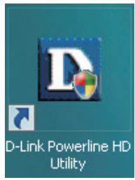
After you have completed the D-Link Powerline Utility installation wizard, double-click the D-Link Powerline HD Utility icon on your desktop to start the configuration of the DHP-302.
Double-click the D-Link Powerline HD Utility icon
The utility provides you with the option of setting your own unique Network ID and the ability to prioritize traffic passing through the network. The color of text on the Device Name, Network ID, MAC, and Location columns represent the status of powerline network.
- Green text - Powerline network is encrypted with a non-default Network ID.
- Red text - Powerline network is encrypted with the default Network ID.
- Grey text - Powerline network is not connected due to a different Network ID.
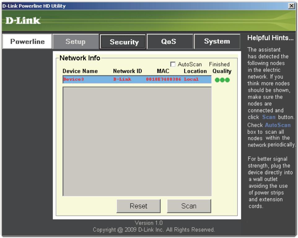
Red text on the Device Name, Network ID, MAC & Location columns mean that the powerline network is encrypted with the default Network ID (D-Link). Follow the steps below to encrypt the network with a non-default Network ID:
- Single-click on the nodes that you want to change.
- Once all the nodes you want to encrypt with a non-default Network ID are highlighted, click the Security page.
- Change to different Network ID.
- Press Save Settings.
Setup
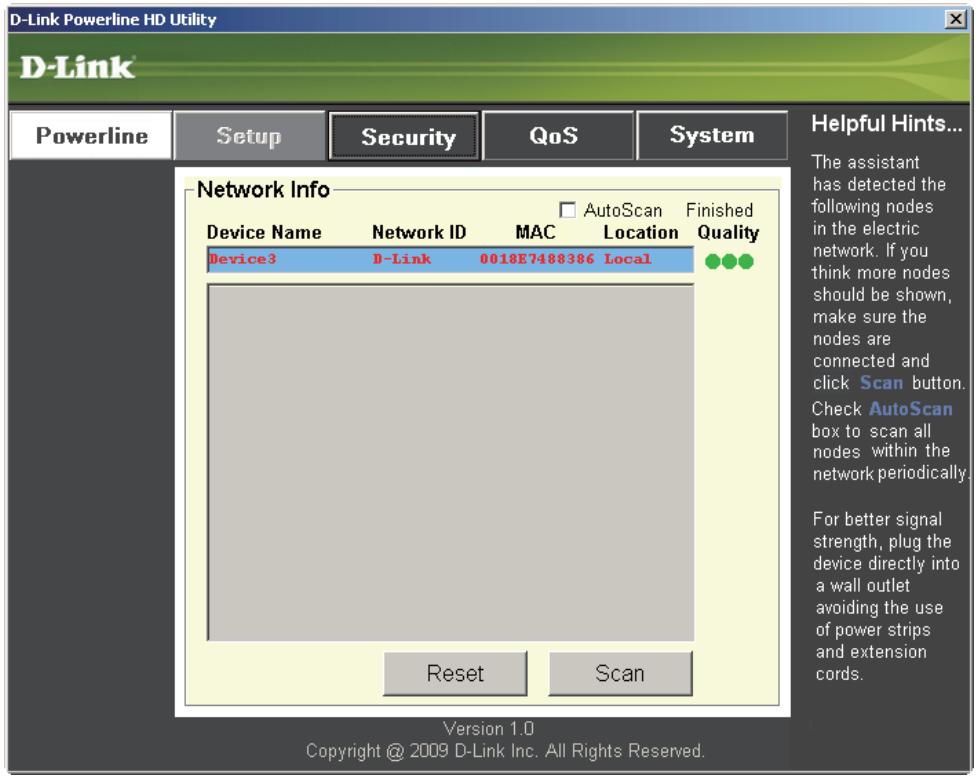
This screen shows the current configuration of the DHP-302.
Device Name: Show name of devices that have been discovered. Default is Device 1, Device 2 etc (Max 16 characters, 0-9, A-Z, case sensitive) ie. Living room, Bedroom, etc.
Network ID: Powerline Network Name. The default ID is D-Link (Max 10 characters, 0-9, A-Z, case sensitive).
MAC: MAC Address of detected node.
Location: Local or Remote nodes.
Quality: Network connection quality of the connected node.
- Three circles - Best powerline connection. Suitable for HD video stream connection.
- Two circles - Better powerline connection. Suitable for SD video stream connection.
- One circle - Good powerline connection. Suitable for data and Internet activity connection.
Scan: Scan the powerline network for PLC nodes. Check the AutoScan box to scan the network periodically.
Note: Network ID can be changed to prevent unauthorized access to your powerline network. Make sure the Network ID of the devices within your powerline network are the same to enable data transmission.
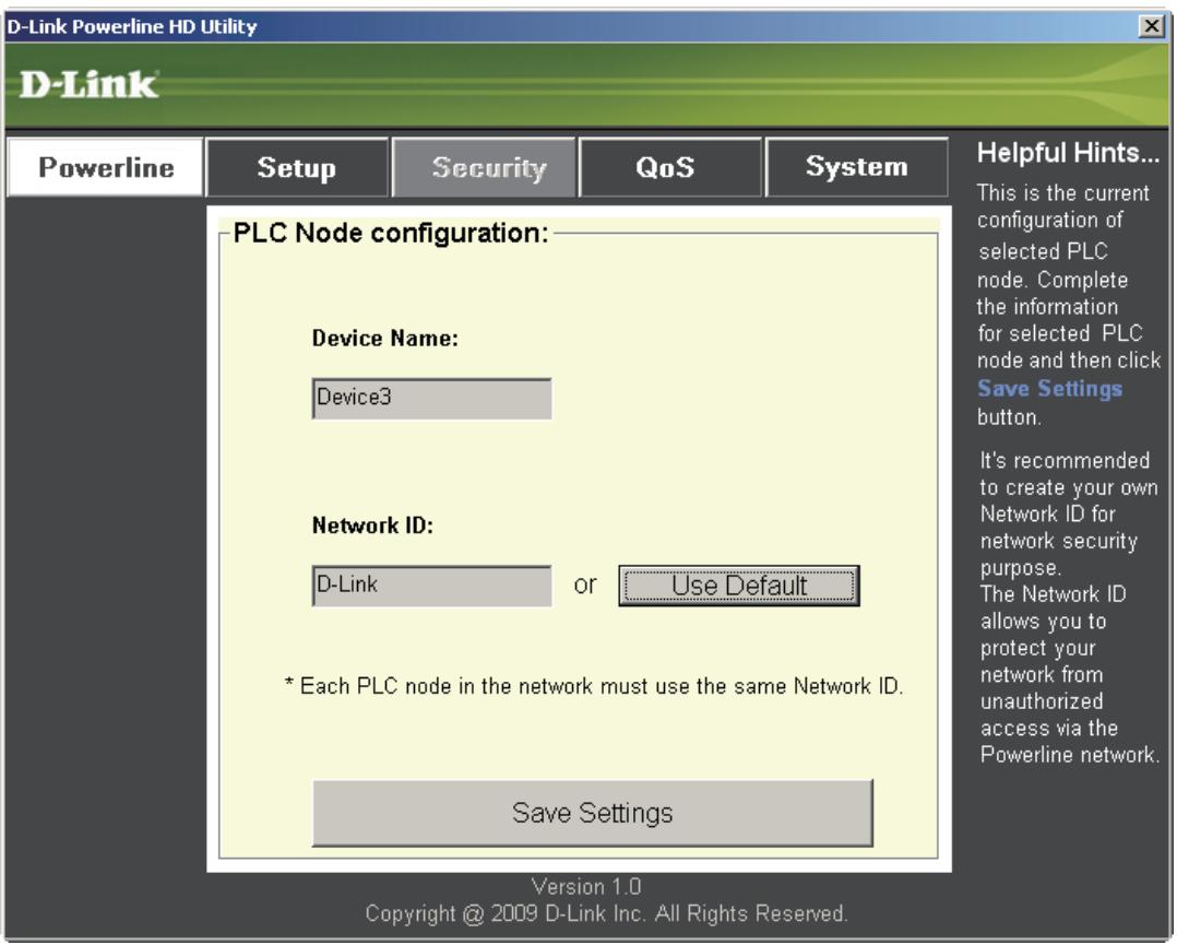
Security
This section shows the security configuration of the DHP-302. You can modify any of the parameters and click Save Setting to save your configuration.
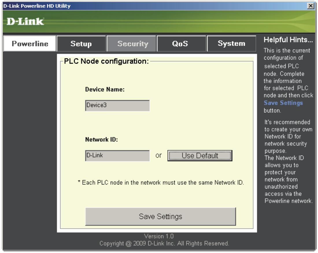
Device Name: Show name of devices that have been discovered. Default is Device 1, Device 2 etc (Max 16 characters, 0-9, A-Z, case sensitive) ie. Living room, Bedroom, etc.
Network ID: Powerline Network Name (Max 10 characters, 0-9, A-Z, case sensitive). Default is D-Link.
Use Default button: Select to reset the Network ID to the default value (D-Link)
Application QoS
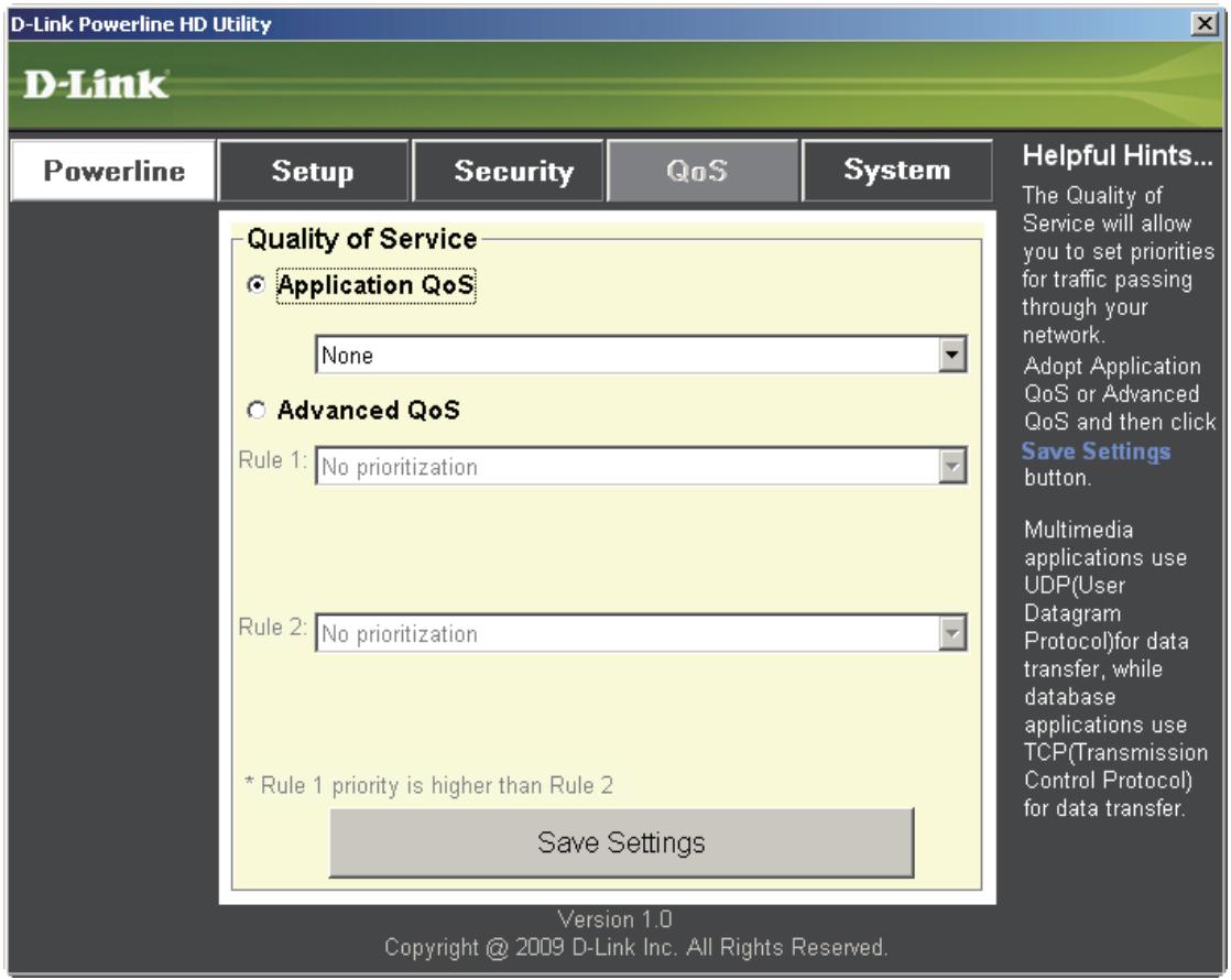
The Quality of Service (QoS) screen will allow you to set priorities for traffic passing through your network. By default all types of traffic are assigned the same priority. Multimedia applications use UDP (User Datagram Protocol) for data transfer, while database applications use TCP (Transmission Control Protocol) for data transfer.
Application QoS: Select an application from the drop-down menu of predefined QoS rules to apply QoS automatically. Click the Save Settings button to apply your settings.
Advanced QoS
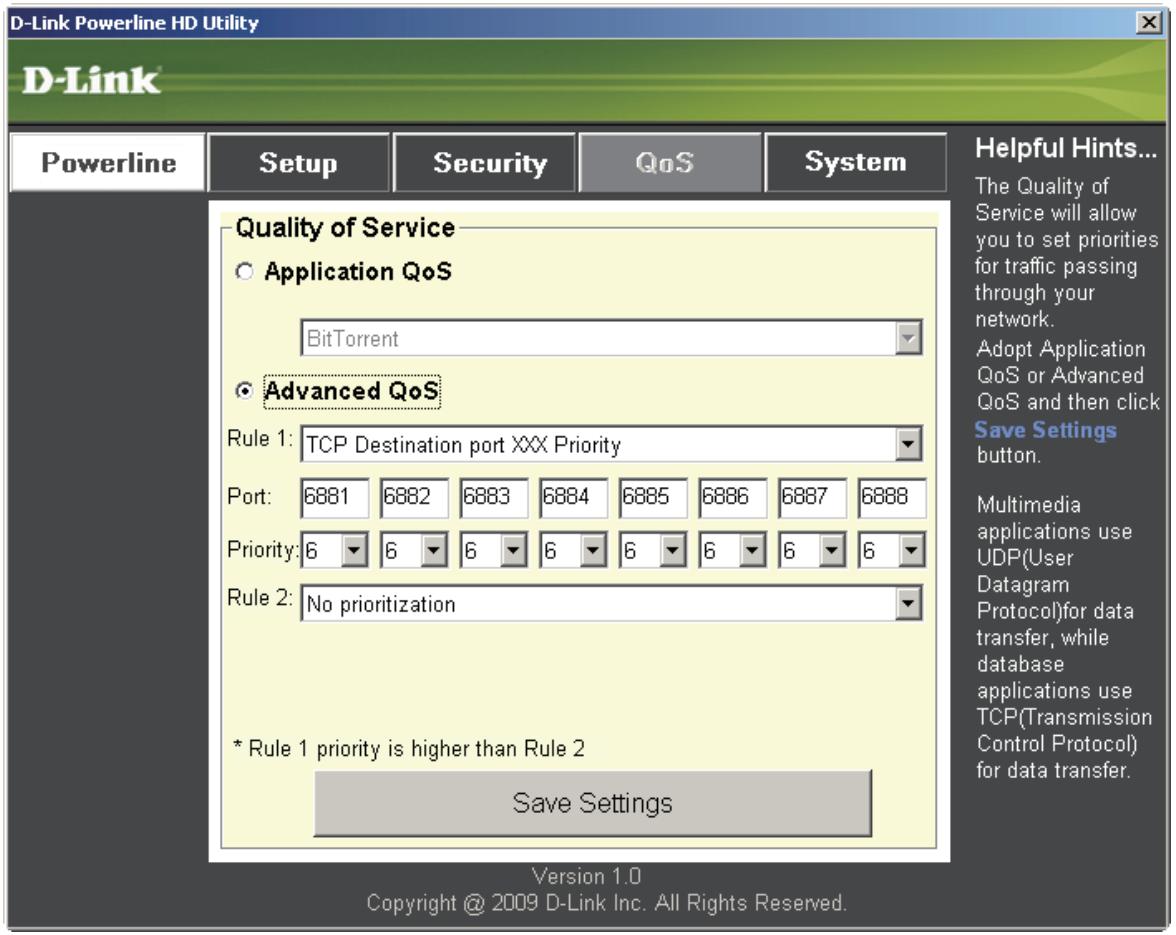
Rule: Select the traffic type (UDP or TCP) to have priority. 802.1p use prioritization bits in Layer-2 frames.
Port: Input the port number to have priority.
Priority: Input port priority from 1 to 6. The highest priority is 6, and the lowest is 1.
Note: Rule 1 has priority over Rule 2
System
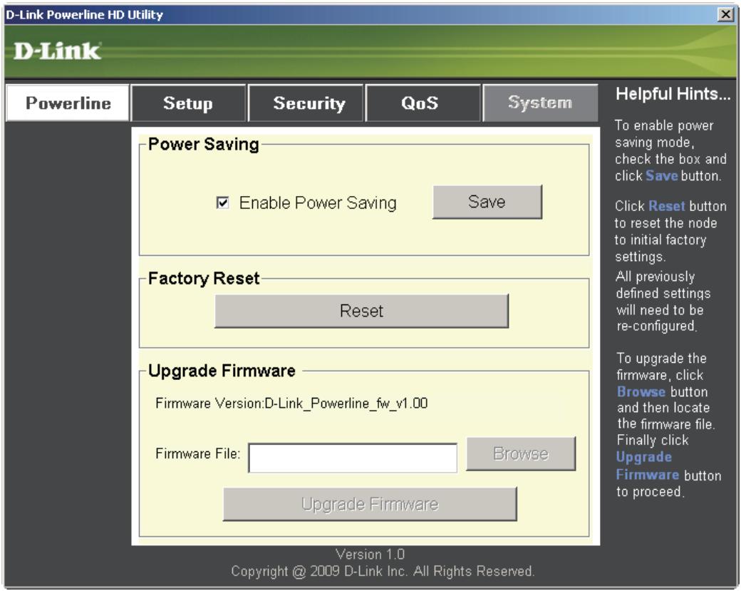
With the power saving mode enabled and the ethernet link activity being down for 15 minutes, the DHP-302 will automatically go into stand-by mode. When the master unit is in stand-by mode, the throughput LED will blink red intermittently.
To reset your configuration password, please click Reset to restore the password to the factory default value.
Troubleshooting
• Powerline HD utility does not start correctly:
Reinstall the utility.
- Powerline HD utility does not detect the PowerLine HD Network Switch:
Please make sure your Powerline HD Network Switch is correctly plugged and connected to the computer or network device.
- I can't configure any parameter of the PowerLine HD Network Switch, an error is shown when I try to configure it:
Please make sure you have not unplugged the PowerLine HD Network Switch while configuring it.
- I changed the connection cable to another Network adapter and now the utility does not work correctly:
Please restart the utility each time you disconnect the connection cable.
- I’m having a lot of problems configuring my network:
If you are having many problems configuring the network with two or more PowerLine HD Network Switch, please make a reset to all of the Network adapters, reset the utility and start configuring the adapter again.
Technical Specifications
Network Ports
• One 10/100 Ethernet port
EMC
• FCC Part 15 Class B
- CE Class B
• C-Tick
AC Input
• 100 \~ 240VAC 50\~60Hz
Safety
- UL 60950
Encryption
• 3DES
Operation Temperature
• 0^ C \~ 40^ C
Storage Temperature
- 10^ 70^
Humidity
• Operation: 10% \~ 90% RH
• Storage: 5% \~ 90% RH
- Table of Contents
- Product Overview....3
- Hardware Installation 7
- Using the Setup Wizard 11
- Configuration....13
- Troubleshooting 21
- Technical Specifications....22
- Package Contents
- System Requirements
- Introduction
- Features
- Hardware Overview LEDs
- Throughput LED
- Hardware Overview Connection
- Hardware Installation
- Power
- Connect the Ethernet Cable
- Push Button Security
- Local adapter
- Local adapter
- Remote (additional) adapters
- Using the Setup Wizard
- Configuration
- Setup
- Security
- Application QoS
- Advanced QoS
- System
- Troubleshooting
- Technical Specifications
- Network Ports
- EMC
- AC Input
- Safety
- Encryption
- Operation Temperature
- Storage Temperature
- Humidity
Brand : D-LINK
Model : DHP-302
Category : Powerline Adapter