
DGS-1100-24P - Network switch D-LINK - Free user manual and instructions
Find the device manual for free DGS-1100-24P D-LINK in PDF.

| Product Type | Gigabit PoE+ Network Switch |
| Brand | D-Link |
| Model | DGS-1100-24P |
| Number of Ports | 24 Gigabit Ethernet ports (10/100/1000 Mbps) |
| PoE Ports | 24 PoE+ ports (802.3at) with total budget of 190 W |
| Dimensions (W x D x H) | 440 x 200 x 44 mm (1U) |
| Weight | Approximately 2.8 kg |
| Power Supply | 100-240 V AC, 50-60 Hz, 3 A (internal) |
| Maximum Power Consumption | 200 W (with PoE) |
| Management | Unmanaged (Plug-and-Play) with basic functions (VLAN, QoS, IGMP Snooping via D-Link SmartConsole) |
| Cooling Type | Active fan |
| Mounting | 19-inch rack, 1U (mounting kit included) |
| Operating Temperature | 0 °C to 40 °C |
| Operating Humidity | 10% to 90% (non-condensing) |
| Certifications | CE, FCC Class A, cUL, LVD, etc. |
| Warranty | 5 years (according to D-Link) |
| Box Contents | Switch, power cable, mounting kit, user manual (PDF), CD with utilities |
| Languages of the Manual | French, English (downloadable PDF) |
Frequently Asked Questions - DGS-1100-24P D-LINK
User questions about DGS-1100-24P D-LINK
0 question about this device. Answer the ones you know or ask your own.
Ask a new question about this device
Download the instructions for your Network switch in PDF format for free! Find your manual DGS-1100-24P - D-LINK and take your electronic device back in hand. On this page are published all the documents necessary for the use of your device. DGS-1100-24P by D-LINK.
USER MANUAL DGS-1100-24P D-LINK
DGS-1100-16/18/24/26/24P
WEB UI REFERENCE GUIDE
Ver. 1.00
Information in this document is subject to change without notice.
© 2014 D-Link Corporation. All rights reserved.
Reproduction in any manner whatsoever without the written permission of D-Link Corporation is strictly forbidden.
Trademarks used in this text: D-Link and the D-Link logo are trademarks of D-Link Corporation; Microsoft and Windows are registered trademarks of Microsoft Corporation.
Other trademarks and trade names may be used in this document to refer to either the entities claiming the marks and names or their products. D-Link Corporation disclaims any proprietary interest in trademarks and trade names other than its own.
FCC Warning
This equipment has been tested and found to comply with the limits for a Class A digital device, pursuant to Part 15 of the FCC Rules. These limits are designed to provide reasonable protection against harmful interference when the equipment is operated in a commercial environment. This equipment generates, uses, and can radiate radio frequency energy and, if not installed and used in accordance with this user's guide, may cause harmful interference to radio communications. Operation of this equipment in a residential area is likely to cause harmful interference in which case the user will be required to correct the interference at his own expense.
CE Mark Warning
This is a Class A product. In a domestic environment, this product may cause radio interference in which case the user may be required to take adequate measures.
Warning!
Audience 1
Other Documentation. 1
Conventions 1
Notes, Notices, and Cautions 2
-
Product Introduction 3
DGS-1100-16 3
Front Panel 3
Rear Panel 3
DGS-1100-18 4
Front Panel 4
Rear Panel 4
DGS-1100-24 5
Front Panel 5
Rear Panel 5
DGS-1100-24P 6
Front Panel 6
Rear Panel 6
DGS-1100-26 7
Front Panel 7
Rear Panel 7 -
Hardware Installation 8
Step 1: Unpacking. 8
Packing contents of DGS-1100-16/18/24/24P/26 8
Step 2: Switch Installation 8
Desktop or Shelf Installation 8
Rack Installation 9
Step 3 - Plugging in the AC Power Cord. 10
Power Failure 10
Grounding the Switch 10
- Web-based Switch Configuration 12
Management Options. 12
Connecting using the Web User Interface 12
Logging onto the Web Manager 13
Smart Wizard 14
Web User Interface (Web UI) 17
Areas of the User Interface 17
- System 18
Device Information 18
System Information Settings 19
IPv4 Interface 19
IPv6 Interface 20
Port Configuration 20
Port Settings 20
Jumbo Frame 21
PoE (DGS-1100-24P Only) 23
PoE System 23
PoE Status 24
PoE Configuration 25
System Log 26
System Log Settings 26
System Log Server Settings 26
System Log 27
Time 28
Clock Settings 28
Time Zone Settings 28
SNTP Settings 29
Time Profile 30
6. Management 31
User Account Settings 31
SNMP 32
SNMP Global Settings 33
SNMP Community Table Settings 33
SNMP Host Table Settings 34
HTTP/HTTPS 35
D-Link Discovery Protocol 35
7. Layer 2 Features 36
FDB 36
Static FDB 36
MAC Address Table Settings 37
MAC Address Table 38
VLAN 39
802.1Q VLAN 39
Port-based VLAN 39
Management VLAN 40
Asymmetric VLAN 40
VLAN Interface 40
Auto Surveillance VLAN 43
Voice VLAN 45
Spanning Tree 48
STP Global Settings 49
STP Port Settings 49
Loopback Detection 50
Link Aggregation 52
L2 Multicast Control 55
IGMP Snooping 55
Multicast Filtering 57
LLDP 58
LLDP Global Settings 58
LLDP Neighbor Port Information 58
8. Quality of Service (QoS) 59
802.1p Priority 59
Port Rate Limiting 60
9. Security 61
Safeguard Engine 61
Safeguard Engine Settings 61
Traffic Segmentation Settings 62
Storm Control 63
DoS Attack Prevention Settings 63
Zone Defense Settings 64
SSL 65
SSL Global Settings 65
10. OAM 66
Cable Diagnostics 66
11. Monitoring 67
Statistics 67
Port Counters 67
Mirror Settings 68
12. Green 69
Power Saving 69
EEE 71
13. Save and Tools 72
Save Configuration 72
Firmware Information 72
Firmware Upgrade & Backup 72
Firmware Upgrade from HTTP 73
Firmware Upgrade from TFTP 73
Firmware Backup to HTTP 73
Firmware Backup to TFTP 74
Configuration Restore & Backup 75
Configuration Restore from HTTP 75
Configuration Restore from TFTP 75
Configuration Backup to HTTP 76
Configuration Backup to TFTP 76
Log Backup 77
Log Backup to HTTP 77
Log Backup to TFTP 77
Ping 78
Reset 78
Reboot System 79
14. Appendix A - Ethernet Technology 80
Gigabit Ethernet Technology 80
Fast Ethernet Technology 80
Switching Technology 81
15. Appendix B - Technical Specifications 82
Hardware Specifications 82
Key Components / Performance 82
Port Functions 82
Physical & Environment 82
Emission (EMI) Certifications. 82
Safety Certifications 82
Features 82
L2 Features 82
L2 Multicasting 82
VLAN 82
QoS (Quality of Service) 83
Security 83
Management 83
Power Saving. 83
- Appendix C - Rack mount Instructions 84
1. Introduction
This manual's command descriptions are based on the software release 1.00. The commands listed here are the subset of commands that are supported by the DGS-1100 Series switch.
Audience
This reference manual is intended for network administrators and other IT networking professionals responsible for managing the switch by using the Web User Interface (Web UI). The Web UI is the secondary management interface to the DGS-1100 Series switch, which will be generally be referred to simply as "the Switch" within this manual. This manual is written in a way that assumes that you already have the experience and knowledge of Ethernet and modern networking principles for Local Area Networks.
Other Documentation
The documents below are a further source of information in regards to configuring and troubleshooting the switch. All the documents are available either from the CD, bundled with this switch, or from the D-Link website. Other documents related to this switch are:
Getting started Guide
D-Link Network Assistant (DNA) User Guide
Conventions
| Convention | Description |
| Boldface Font | Indicates a button, a toolbar icon, menu, or menu item. For example: Open the File menu and choose Cancel. Used for emphasis. May also indicate system messages or prompts appearing on screen. For example: You have mail. Bold font is also used to represent filenames, program names and commands. For example: use the copy command. |
| Initial capital letter | Indicates a window name. Names of keys on the keyboard have initial capitals. For example: Click Enter. |
| Menu Name > Menu Option | Indicates the menu structure. Device > Port > Port Properties means the Port Properties menu option under the Port menu option that is located under the Device menu. |
| Blue Courier Font | This convention is used to represent an example of a screen console display including example entries of CLI command input with the corresponding output. |
Notes, Notices, and Cautions
Below are examples of the three types of indicators used in this manual. When administering your switch using the information in this document, you should pay special attention to these indicators. Each example below provides an explanatory remark regarding each type of indicator.

NOTE: A note indicates important information that helps you make better use of your device.

NOTICE: A notice indicates either potential damage to hardware or loss of data and tells you how to avoid the problem.

CAUTION: A caution indicates a potential for property damage, personal injury, or death.
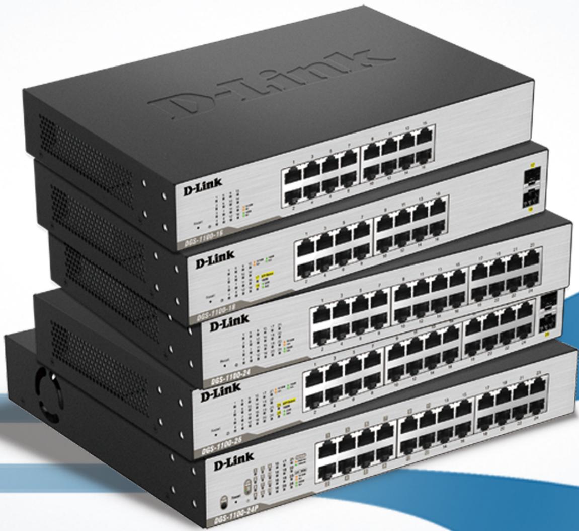
2. Product Introduction
Thank you and congratulations on your purchase of D-Link DGS-1100 Series Switch Products.
D-Link's next generation DGS-1100 Series switches blends plug-and-play simplicity with exceptional value and reliability for small and medium-sized business (SMB) networking. All models are housed in a new style rack-mount metal case with easy-to-view front panel diagnostic LEDs.
The brand-new DGS-1100 series are born to be green by design of IEEE 802.3az Energy Efficient Ethernet compliant (abbreviated as EEE) and D-Link Green Technologies. It allows significant power saving during periods of low data activity. In most of use cases and environments, switches are idle in 90% or more of time. While no traffic in a short period of time, ports on DGS-1100 switch get into power saving mode automatically. Once if a packet is received, the switch wakes and works immediately. Connecting to EEE compliant devices, such as PCs and servers, the network can save energy without compromising any performance. While connecting to legacy devices which do not support IEEE 802.3az, D-Link Green Technologies can reduce power consumption by changing the power state of the link.
DGS-1100-16
16-Port 10/100/1000Mpbs Switch
Front Panel

Figure 2-1 - DGS-1100-16 Front Panel
Power LED: The Power LED lights up when the Switch is connected to a power source.
Link/Act/Speed LED (Ports 1-16):
Solid Green: When there is a secure 1000Mbps connection at the port.
Blinking Green or Amber: Indicates that the Switch is either sending or receiving data to the port.
Solid Amber: Indicates that the port is running at 10/100Mbps.
Light off: No link.
Reset: By pressing the Reset button until the power LED turns amber, the Switch will change back to the default configuration and all changes will be lost.
Rear Panel
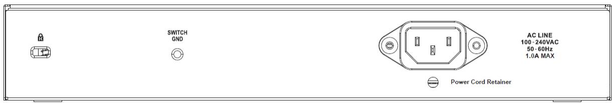
Figure 2-2 - DGS-1100-16 Rear Panel
Power: The power port is where to connect the AC power cord.
DGS-1100-18
16-Port 10/100/1000Mbps + 2 Port SFP 1000 Mbps Switch
Front Panel
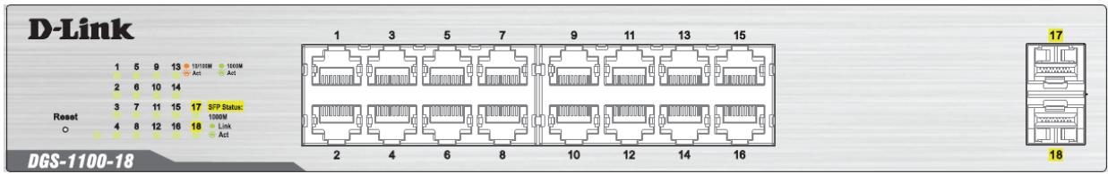
Figure 2-3 - DGS-1100-18 Front Panel
Power LED: The Power LED lights up when the Switch is connected to a power source.
Link/Act/Speed LED (Ports 1-16):
Solid Green: When there is a secure 1000Mbps connection at the port.
Blinking Green or Amber: Indicates that the Switch is either sending or receiving data to the port.
Solid Amber: Indicates that the port is running at 10/100Mbps.
Light off: No link.
Link/Act/Speed LED (Ports 17-18):
Solid Green: There is a secure 1000Mbps connection at the port.
Blinking Green: There is reception or transmission occurring at the port.
Light off: No link.
Reset: By pressing the Reset button until the power LED turns amber, the Switch will change back to the default configuration and all changes will be lost.
Rear Panel
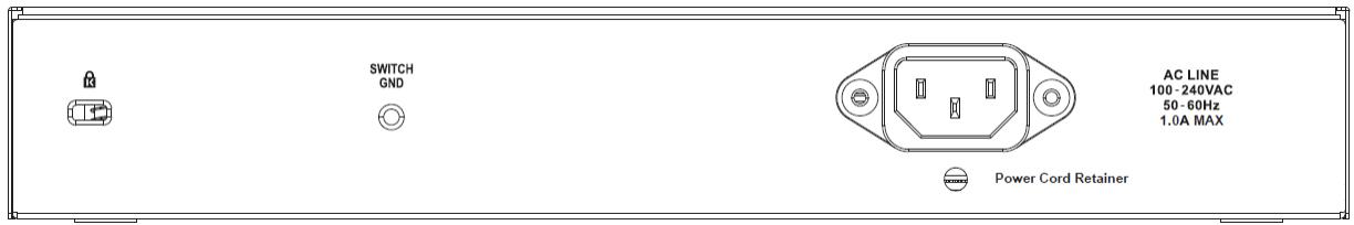
Figure 2-4 - DGS-1100-18 Rear Panel
Power: The power port is where to connect the AC power cord.
DGS-1100-24
24-Port 10/100/1000Mpbs Switch
Front Panel
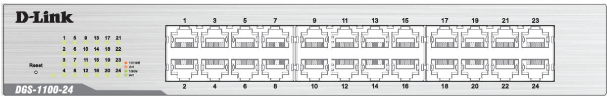
Figure 2-5 - DGS-1100-24 Front Panel
Power LED: The Power LED lights up when the Switch is connected to a power source.
Link/Act/Speed LED (Ports 1-24):
Solid Green: When there is a secure 1000Mbps connection at the port.
Blinking Green or Amber: Indicates that the Switch is either sending or receiving data to the port.
Solid Amber: Indicates that the port is running at 10/100 Mbps.
Light off: No link.
Reset: By pressing the Reset button until the power LED turns amber, the Switch will change back to the default configuration and all changes will be lost.
Rear Panel
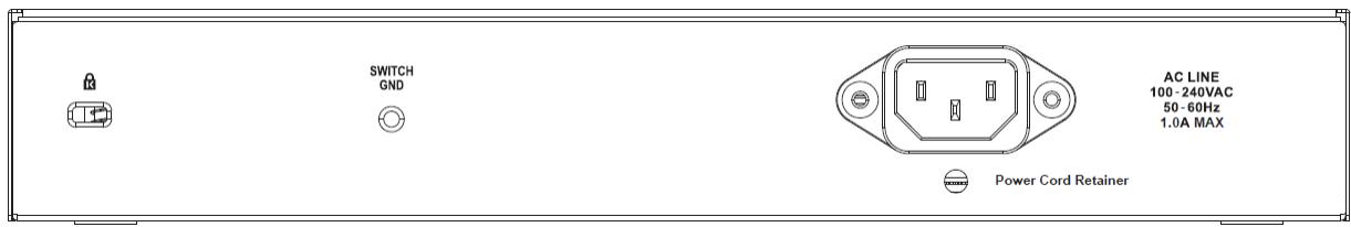
Figure 2-6 - DGS-1100-24 Rear Panel
Power: Connect the supplied AC power cable to this port.
DGS-1100-24P
24-Port 10/100/1000Mpbs PoE Switch
Front Panel
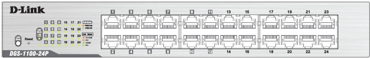
Figure 2-7 - DGS-1100-24P Front Panel
Power LED: The Power LED lights up when the Switch is connected to a power source.
Link/Act/Speed LED (Ports 1-24):
Solid Green: When there is a secure 1000Mbps connection at the port.
Blinking Green or Amber: Indicates that the Switch is either sending or receiving data to the port.
Solid Amber: Indicates that the port is running at 10/100Mbps.
Light off: No link.
PoE Mode (Ports 1-12):
Green: Indicates that PoE mode is active.
Amber: Indicates that there is an issue with the PoE mode activating properly.
Light off: Indicates that PoE mode is not active.
LED Mode Button: Pressing this button will change the LED behavior from Link mode, and PoE Mode
Reset: By pressing the Reset button until the power LED turns amber, the Switch will change back to the default configuration and all changes will be lost.
Note: The LED behavior for ports 1-12 will switch between Link mode and PoE mode when the PoE mode is active.
Rear Panel
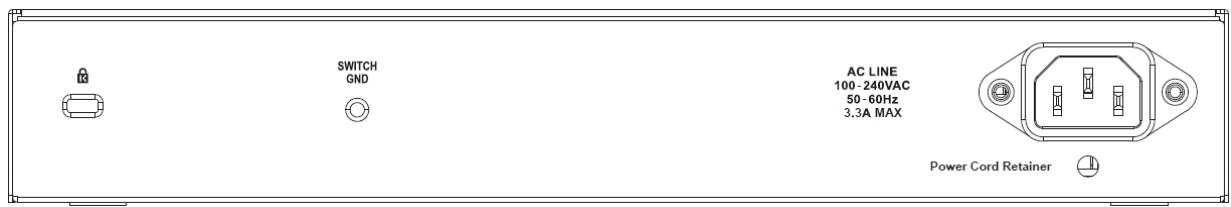
Figure 2-8 - DGS-1100-24P Rear Panel
Power: Connect the supplied AC power cable to this port.
DGS-1100-26
24-Port 10/100/1000Mbps + 2 Port SFP 1000 Mbps Switch
Front Panel
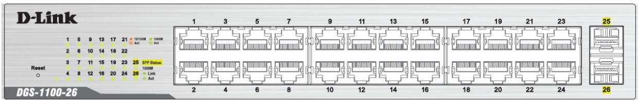
Figure 2-9 - DGS-1100-26 Front Panel
Power LED: The Power LED lights up when the Switch is connected to a power source.
Link/Act/Speed LED (Ports 1-24):
Solid Green: When there is a secure 1000Mbps connection at the port.
Blinking Green or Amber: Indicates that the Switch is either sending or receiving data to the port.
Solid Amber: Indicates that the port is running at 10/100Mbps.
Light off: No link.
Link/Act/Speed LED (Ports 25-26):
Solid Green: There is a secure 1000Mbps connection at the port.
Blinking Green: There is reception or transmission occurring at the port.
Light off: No link.
Reset: By pressing the Reset button until the power LED turns amber, the Switch will change back to the default configuration and all changes will be lost.
Rear Panel

Figure 2-10 - DGS-1100-26 Rear Panel
Power: Connect the supplied AC power cable to this port.
3. Hardware Installation
This chapter provides unpacking and installation information for the D-Link Switch.
Step 1: Unpacking
Open the shipping carton and carefully unpack its contents. Please consult the packing list located in the User Manual to make sure all items are present and undamaged. If any item is missing or damaged, please contact your local D-Link reseller for replacement.
Packing contents of DGS-1100-16/18/24/24P/26
One D-Link DGS-1100 Series Switch
One AC power cord
Four rubber feet
- Screws and two mounting brackets
One accessory kit for a ground screw
One Multi-lingual Getting Started Guide
One CD with User Manual
If any item is found missing or damaged, please contact the local reseller for replacement.
Step 2: Switch Installation
For safe switch installation and operation, it is recommended that you:
- Visually inspect the power cord to see that it is secured fully to the AC power connector.
- Make sure that there is proper heat dissipation and adequate ventilation around the switch.
- Do not place heavy objects on the switch.
Desktop or Shelf Installation
When installing the switch on a desktop or shelf, the rubber feet included with the device must be attached on the bottom at each corner of the device's base. Allow enough ventilation space between the device and the objects around it.
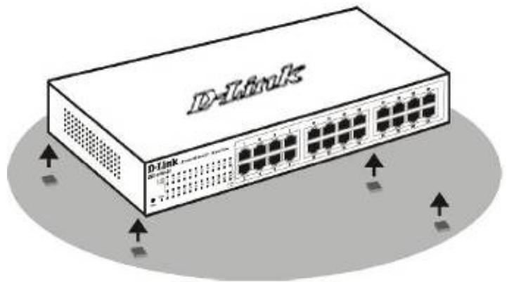
Figure 3-1 - Attach the adhesive rubber pads to the bottom
Rack Installation
The switch can be mounted in an EIA standard size 11-inch rack, which can be placed in a wiring closet with other equipment. To install, attach the mounting brackets to the switch's side panels (one on each side) and secure them with the screws provided (please note that these brackets are not designed for palm size switches).
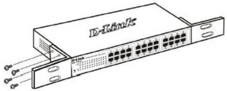
Figure 3-2 - Attach the mounting brackets to the Switch
Then, use the screws provided with the equipment rack to mount the switch in the rack.
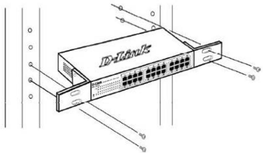
Figure 3-3 - Mount the Switch in the rack or chassis
Please be aware of following safety Instructions when installing:
A) Elevated Operating Ambient - If installed in a closed or multi-unit rack assembly, the operating ambient temperature of the rack environment may be greater than room ambient. Therefore, consideration should be given to installing the equipment in an environment compatible with the maximum ambient temperature (Tma) specified by the manufacturer.
B) Reduced Air Flow - Installation of the equipment in a rack should be such that the amount of air flow required for safe operation of the equipment is not compromised.
C) Mechanical Loading - Mounting of the equipment in the rack should be such that a hazardous condition is not achieved due to uneven mechanical loading.
D) Circuit Overloading - Consideration should be given to the connection of the equipment to the supply circuit and the effect that overloading of the circuits might have on overcurrent protection and supply wiring. Appropriate consideration of equipment nameplate ratings should be used when addressing this concern.
E) Reliable Earthing - Reliable earthing of rack-mounted equipment should be maintained. Particular attention should be given to supply connections other than direct connections to the branch circuit (e.g. use of power strips).
Step 3 - Plugging in the AC Power Cord
Users may now connect the AC power cord into the rear of the switch and to an electrical outlet (preferably one that is grounded and surge protected).
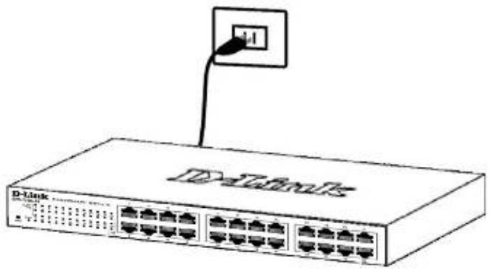
Figure 3-4 - Plugging the switch into an outlet
Power Failure
As a precaution, the switch should be unplugged in case of power failure. When power is resumed, plug the switch back in.
Grounding the Switch
This section describes how to connect the DGS-1100 Series Switch to ground. You must complete this procedure before powering your switch.
Required Tools and Equipment
Ground screws (included in the accessory kit): One M4 x 6 mm (metric) pan-head screw
- Ground cable (not included in the accessory kit): The grounding cable should be sized according to local and national installation requirements. Depending on the power supply and system, a 12 to 6 AWG copper conductor is required for U.S installation. Commercially available 6 AWG wire is recommended. The length of the cable depends on the proximity of the switch to proper grounding facilities.
- A screwdriver (not included in the accessory kit)
The following steps let you connect the switch to a protective ground:
Step 1: Verify if the system power is off.
Step 2: Use the ground cable to place the #8 terminal lug ring on top of the ground-screw opening, as seen in the figure below.
Step 3: Insert the ground screw into the ground-screw opening.
Step 4: Using a screwdriver, tighten the ground screw to secure the ground cable to the switch.
Step 5: Attach the terminal lug ring at the other end of the grounding cable to an appropriate grounding stud or bolt on rack where the switch is installed.
Step 6: Verify if the connections at the ground connector on the switch and the rack are securely attached.
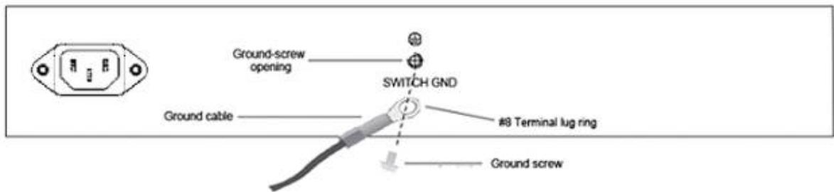
Figure 3-5 - Ground cable, screw and #8 terminal lug rings
4. Web-based Switch Configuration
Management Options
Connecting using the Web User Interface
Logging onto the Web Manager
Smart Wizard
Web User Interface (Web UI)
Management Options
The Switch provides multiple access platforms that can be used to configure, manage and monitor networking features available on the Switch. Currently there are three management platforms available and they are described below.
Web-based Management Interface
After successfully installing the Switch, the user can configure the Switch, monitor the LED panel, and display statistics graphically using a Web browser, such as Microsoft® Internet Explorer, Opera Firefox, Safari, or Google Chrome.
SNMP-based Management
The Switch can be managed with an SNMP-compatible console program. The Switch supports SNMP version 1.0, and version 2c. The SNMP agent decodes the incoming SNMP messages and responds to requests with MIB objects stored in the database. The SNMP agent updates the MIB objects to generate statistics and counters.
D-Link Network Assistant
DNA (D-Link Network Assistant) included on the installation CD is a program for discovering DGS-1100 Series Switches with the same L2 network segment connected to your PC. This tool can support windows 2000, XP, Vista, and Windows 7.
Connecting using the Web User Interface
Most software functions of the DGS-1100 Series switches can be managed, configured and monitored via the embedded web-based (HTML) interface. Manage the Switch from remote stations anywhere on the network through a standard web browser. The web browser acts as a universal access tool and can communicate directly with the Switch using the HTTP or HTTPS protocol.
You need the following equipment to begin the web configuration of your device:
- A PC with a RJ-45 Ethernet connection
A standard Ethernet cable
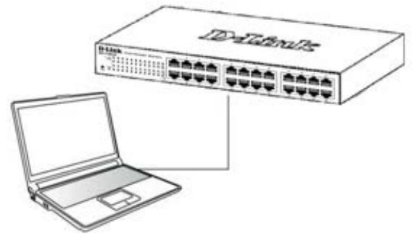
Figure 4-1 – Connecting to a DGS-1100 Series Switch
Connect the Ethernet cable to any of the ports on the front panel of the switch and to the Ethernet port on the PC.
Logging onto the Web Manager
To access the Web User Interface, simply open a standard web browser on the management PC and enter the Switch's default IP address into the address bar of the browser and press the Enter key.

NOTE: The default IP address of this switch is 10.90.90.90, with a subnet mask of 255.0.0.0.

Figure 4-2 Displays entering the IP address in Internet Explorer
This will open the user authentication window, as seen below.
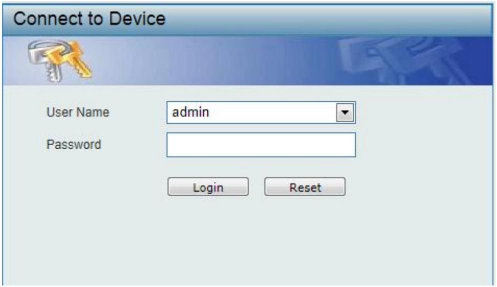
Figure 4-3 User Authentication window
By default, the username is "admin" and the password is also "admin". Click the Login button.
Smart Wizard
After a successfully connecting to the Web User Interface for the first time, the Smart Wizard embedded Web utility will be launched. This wizard will guide the user through basic configuration steps that is essential for first time connection to the Switch.
Step 1 - System IP Information
In this window, the user can configure the IP address assignment method, the static IP address, Netmask and Gateway address.
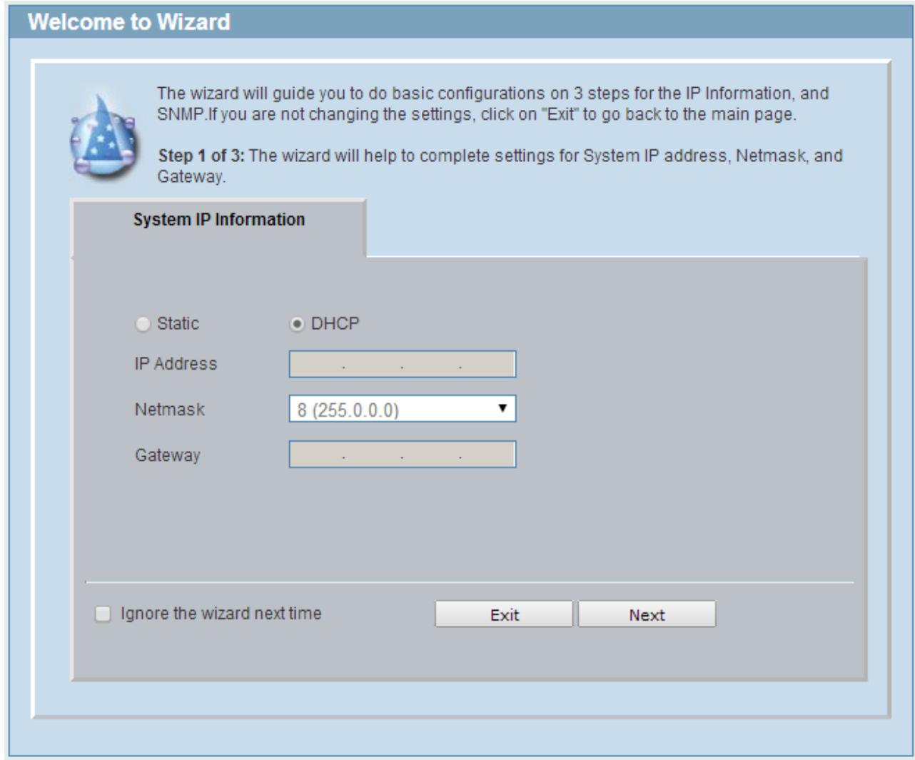
Figure 4-4 System IP Information window
The fields that can be configured are described below:
| Parameter | Description |
| Static | Select this option to manually configure and use IP address settings on this switch. |
| DHCP | Select this option to obtain IP address settings from a DHCP server. |
| IP Address | Enter the IP address of the Switch here. |
| Netmask | Select the Netmask option here. |
| Gateway | Enter the default gateway IP address here. |
Tick the Ignore the wizard next time option to skip the Smart Wizard on the next login.
Click the Exit button to discard the changes made, exit the Smart Wizard, and continue to the Web UI.
Click the Next button to accept the changes made and continue to the next step.
Step 2 – Admin Password
In this window, the user can set the password used with the admin account.
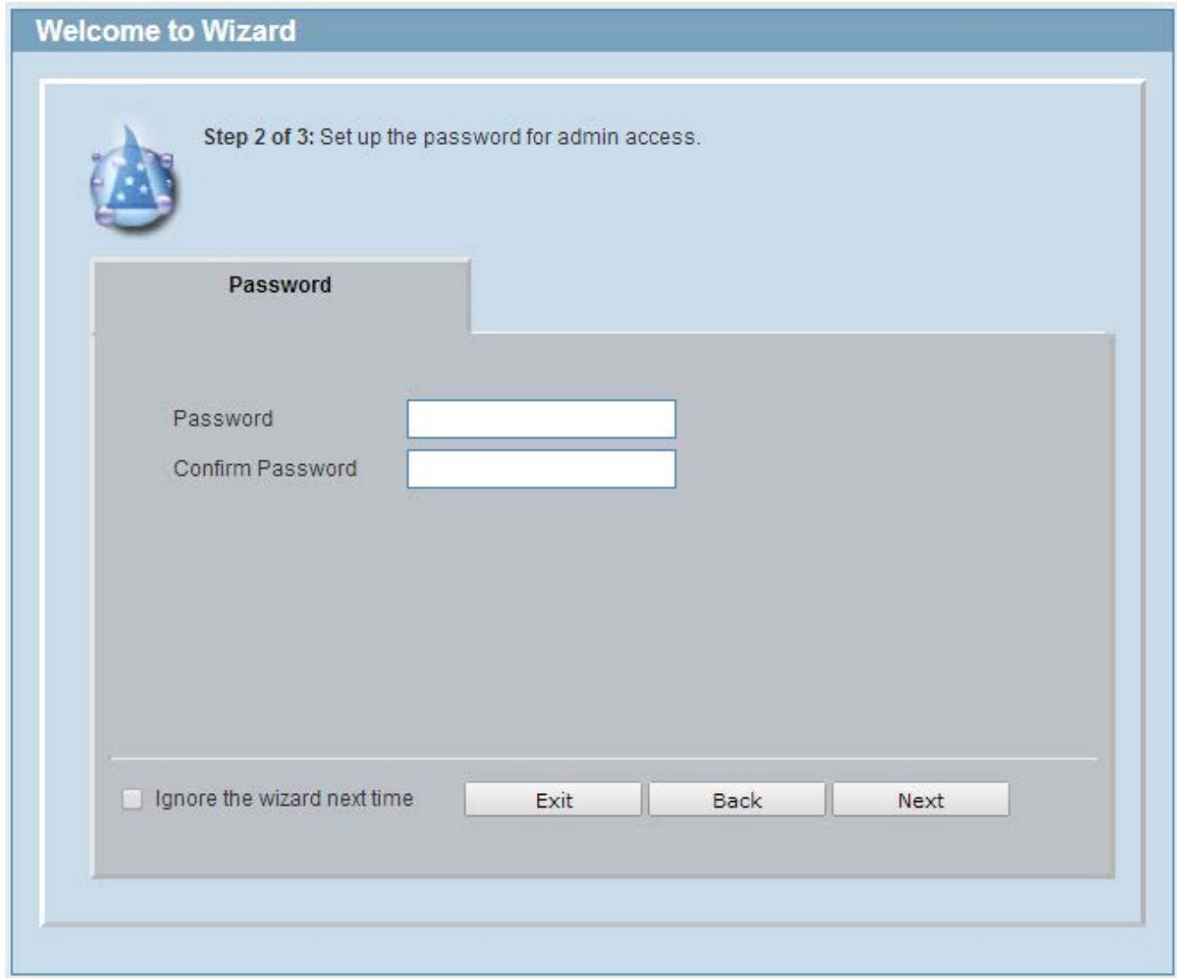
Figure 4-5 Admin Password
Tick the Ignore the wizard next time option to skip the Smart Wizard on the next login.
Click the Exit button to discard the changes made, exit the Smart Wizard, and continue to the Web UI.
Click the Next button to accept the changes made and continue to the next step.
Step 3 - SNMP Settings
In this window, the user can enable or disable the SNMP function.
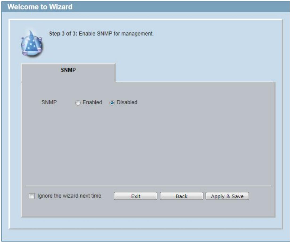
Figure 4-6 SNMP window
The fields that can be configured are described below:
| Parameter | Description |
| SNMP | Select the Enabled option to enable the SNMP function. Select the Disabled option to disable the SNMP function. |
Tick the Ignore the wizard next time option to skip the Smart Wizard on the next login.
Click the Exit button to discard the changes made, exit the Smart Wizard, and continue to the Web UI.
Click the Apply & Save button to accept the changes made, and then continue to the Web UI.
Web User Interface (Web UI)
By clicking the Exit button in the Smart Wizard, you will enter the Web-based Management interface.
Areas of the User Interface
The figure below shows the user interface. Three distinct areas that divide the user interface, as described in the table.
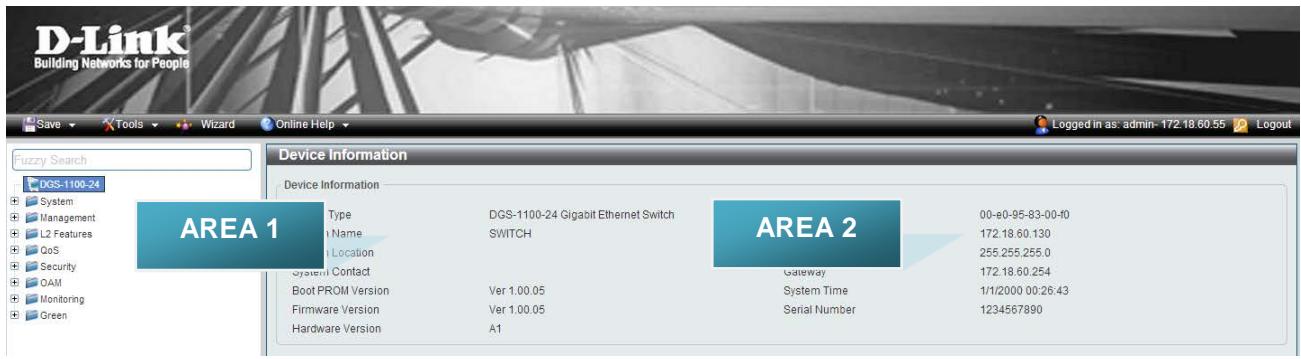
Figure 4-7 Main Web UI window
| Area Number | Description |
| AREA 1 | In this area, a folder tree layout is displayed of functions that can be configured using the Web UI. Open folders and click the hyperlinked menu buttons to access each individual page for configuration. The DGS-1100-24 link is the default page that will display basic monitoring settings for this switch. |
| AREA 2 | In this area, the Switch's configuration page can be found, based on the selection made in Area 1. |
5. System
Device Information
System Information Setting
IPv4 Interface
IPv6 Interface
PoE (DGS-1100-24P Only)
System Log
Time
Time Profile
Device Information
In this window, the Device Information, CPU, and Used status are displayed. It appears automatically when you log in the Switch. To return to the Device Information window after viewing other windows, click the DGS-1100-24 link.
Device Information
Device Information
Device Type
System Name
System Location
System Contact
Boot PROM Version
Firmware Version
Hardware Version
DGS-1100-24 Gigabit Ethernet Switch
SWITCH
Ver 1.00.05
Ver 1.00.05
A1
MAC Address
IP Address
Mask
Gateway
System Time
Serial Number
00-e0-95-83-00-f0
172.18.60.130
255.255.255.0
172.18.60.254
1/1/2000 00:26:43
1234567890
Figure 5-1 Device Information window
System Information Settings
The user can enter a System Name, System Location, and System Contact to aid in defining the Switch.
To view the following window, click System > System Information Settings, as shown below:
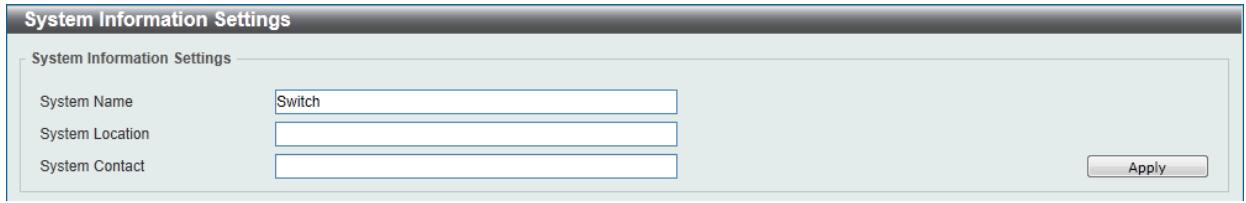
Figure 5-2 System Information Settings window
The fields that can be configured are described below:
| Parameter | Description |
| System Name | Enter a system name for the Switch, if so desired. This name will identify it in the Switch network. |
| System Location | Enter the location of the Switch, if so desired. |
| System Contact | Enter a contact name for the Switch, if so desired. |
Click the Apply button to accept the changes made.
IPv4 Interface
This window is used to configure the IPv4 settings of the switch.
To view the following window, click System > System Information Settings > IPv4 Interface, as shown below:
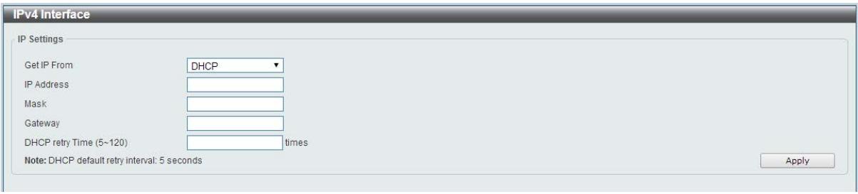
Figure 5-3 Peripheral Settings window
The fields that can be configured are described below:
| Parameter | Description |
| Get IP From | Select DHCP to automatically obtain an IP address. Select Static to manually configure the IP address settings. BOOTP allows the switch to get an IP configuration using the BOOTP protocol. |
| IP Address | If Static is selected, enter the IP address of the switch. If DHCP or BOOTP is selected, the automatically obtained IP address will be displayed. |
| Mask | If Static is selected, enter the IP address of the switch. If DHCP or BOOTP is selected, the automatically obtained network mask will be displayed. |
| Gateway | If Static is selected, enter the IP address of the switch. If DHCP or BOOTP is selected, the automatically obtained gateway will be displayed. |
| DHCP retry Time | If DHCP is selected, enter the number of times to retry obtaining an IP address. |
Click the Apply button to accept the changes made.
IPv6 Interface
This window is used to configure the IPv6 settings of the switch.
To view the following window, click System > System Information Settings > IPv6 Interface, as shown below:
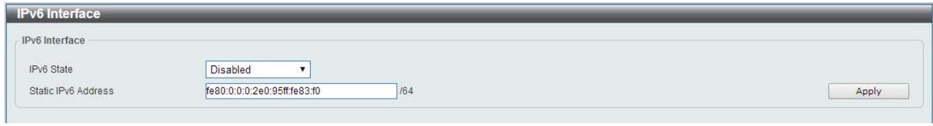
Figure 5-4 Peripheral Settings window
The fields that can be configured are described below:
| Parameter | Description |
| IPv6 State | Select whether to Enable or Disable IPv6 functionality. |
| Static IPv6 Address | If enabled, enter the static IPv6 address of the switch. |
Click the Apply button to accept the changes made.
Port Configuration
Port Settings
This window is used to view and configure the Switch's port settings.
To view the following window, click System > Port Configuration > Port Settings, as shown below:
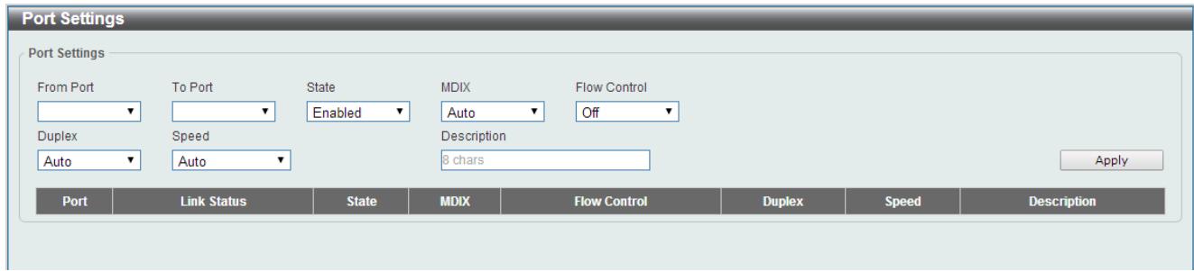
Figure 5-5 Port Settings window
The fields that can be configured are described below:
| Parameter | Description |
| From Port / To Port | Select the appropriate port range used for the configuration here. |
| State | Select this option to enable or disable the physical port here. |
| MDIX | Select the Medium Dependent Interface Crossover (MDIX) option here. Options to choose from are Auto, Normal, and Cross. Auto - Select this option for auto-sensing of the optimal type of cabling. Normal - Select this option for normal cabling. If this option is selected, the port is in the MDIX mode and can be connected to a PC's NIC using a straight-through cable or a port (in the MDIX mode) on another switch through a cross-over cable. Cross - Select this option for cross cabling. If this option is selected, the port is in the MDI mode and can be connected to a port (in the MDIX mode) on another switch through a straight cable. |
| Flow Control | Select to either turn flow control On or Off here. Ports configured for full-duplex use 802.3x flow control, half-duplex ports use back-pressure flow control, and Auto ports use an automatic selection of the two. |
| Duplex | Select the duplex mode used here. Options to choose from are Auto, Half, and Full. |
| Speed | Select the port speed option here. This option will manually force the connected on the selected port to only connect at the speed specified here. Options to choose from are Auto, 10M, 100M. 1000M speed is only available when Auto is selected. |
| Description | Enter a 8 characters description for the corresponding port here. |
Click the Apply button to accept the changes made.
Note: The fiber ports on the DGS-1100-18 and DGS-1100-26 only support Auto for duplex and speed. Also, the fiber ports on the DGS-1100-18 and DGS-1100-26 do not support MDIX.
Jumbo Frame
This window is used to view and configure the Jumbo Frame size and settings. The Switch supports jumbo frames. Jumbo frames are Ethernet frames with more than 1,518 bytes of payload. The Switch supports jumbo frames with a maximum frame size of up to 9216 bytes.
To view the following window, click System > Port Configuration > Jumbo Frame, as shown below:
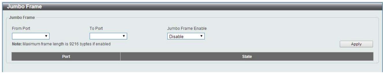
Figure 5-6 Jumbo Frame window
The fields that can be configured are described below:
| Parameter | Description |
| From Port / To Port | Select the appropriate port range used for the configuration here. |
| Jumbo Frame Enable | Select whether to Enable or Disable support for Jumbo Frames on the switch. |
Click the Apply button to accept the changes made.
PoE (DGS-1100-24P Only)
The DGS-1100-24P switch supports Power over Ethernet (PoE) as defined by the IEEE 802.3af and 802.3at. Ports 1 through 12 can support PoE up to 30W. Ports 1-12 can supply about 48 VDC power to Powered Devices (PDs) over Category 5 or Category 3 UTP Ethernet cables. The Switch follows the standard PSE (Power Sourcing Equipment) pinout Alternative A, whereby power is sent out over pins 1, 2, 3 and 6. The Switches work with all D-Link 802.3af capable devices.
The Switch includes the following PoE features:
- Auto-discovery recognizes the connection of a PD (Powered Device) and automatically sends power to it.
- The Auto-enable feature occurs under two conditions: firstly, if the total power consumption exceeds the system power limit; and secondly, if the per port power consumption exceeds the per port power limit.
- Active circuit protection automatically disables the port if there is a short. Other ports will remain active.
Based on 802.3af/at PDs receive power according to the following classification:
| Class | Maximum power used by PD |
| 0 | 12.95W |
| 1 | 3.84W |
| 2 | 6.49W |
| 3 | 12.95W |
| 4 | 25.5W |
PSE provides power according to the following classification:
| Class | Max power supplied by PSE |
| 0 | 16.2W |
| 1 | 4.2W |
| 2 | 7.4W |
| 3 | 16.2W |
| 4 | 31.6W |
PoE System
This window is used to configure the PoE system, and display the detailed power information and PoE Trap parameters for PoE modules.
To view the following window, click System > PoE > PoE System, as shown below:
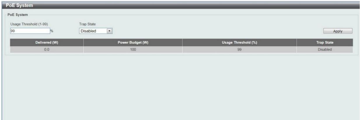
Figure 5-7 PoE System window
The fields that can be configured are described below:
| Parameter | Description |
| Usage Threshold | Enter the usage threshold to generate a log and send the corresponding standard notification. |
| Trap State | Select this option to enable or disable the sending of PoE notifications. |
Click the Apply button to accept the changes made.
PoE Status
This window displays the PoE status of each port.
To view the following window, click System > PoE > PoE Status, as shown below:
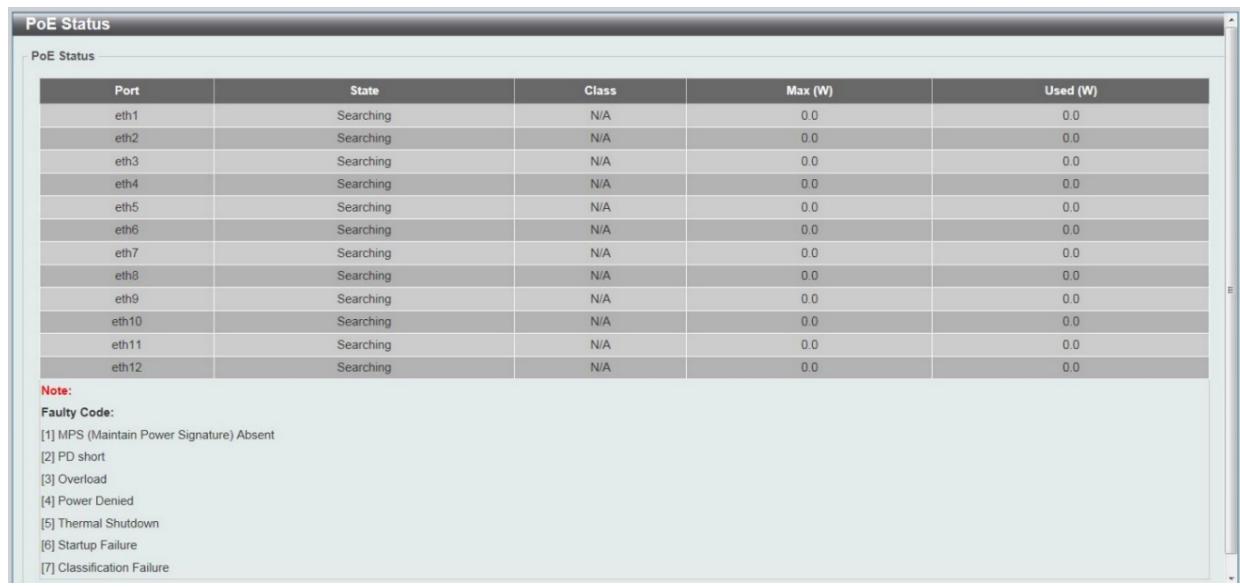
Figure 5-8 PoE Status window
Note: For the PoE Status table, if the classification was shown as "Legacy PD", it will be classified to non-AF PD or Legacy PD.
PoE Configuration
This window is used to configure the PoE port.
To view the following window, click System > PoE > PoE Configuration, as shown below:
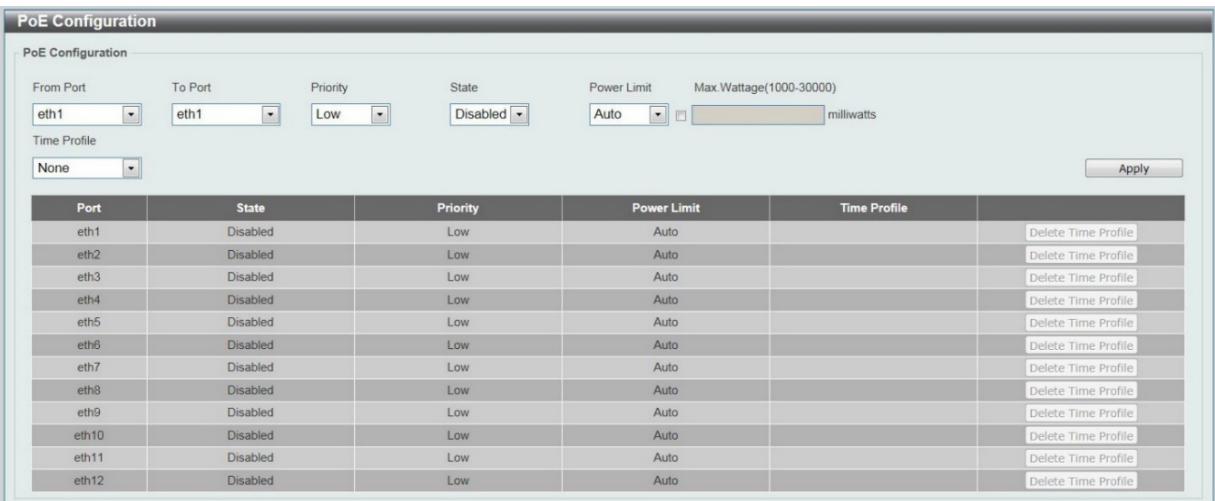
Figure 5-9 PoE Configuration window
The fields that can be configured are described below:
| Parameter | Description |
| From Port / To Port | Select the appropriate port range used for the configuration here. |
| Priority | Select the priority for provisioning power to the port. Options to choose from are Critical, High and Low. |
| State | Select this option to enable or disable the PoE functionality. |
| Power Limit | Select the power management mode for the PoE ports. Options to choose from are Auto, Class 1, Class 2, Class 3, and Class 4. |
| Max Wattage | When selecting Auto in the Mode drop-down list, this option appears. Tick the check box and enter the maximum wattage of power that can be provisioned to the auto-detected PD. If the value is not entered, the class of the PD automatically determines the maximum wattage which can be provisioned. The valid range for maximum wattage is between 1000 mW and 30000 mW. |
| Time Profile | Select the Time Profile from the drop down list. Note: The Time Profile drop down menu will only have available options if a time profile has been created. |
Click the Delete Time Range button to clear the setting in the corresponding Time Range field.
Click the Apply button to accept the changes made.
Note: The Max Wattage option will only be available if the check box next to the input field is enabled. When enabled, the Power Limit drop down menu will not be available.
System Log
System Log Settings
This window is used to view and configure the system's log settings.
To view the following window, click System > System Log > System Log Settings, as shown below:
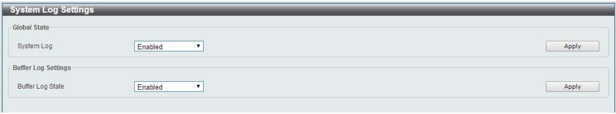
Figure 5-10 System Log Settings window
The fields that can be configured for Global State are described below:
| Parameter | Description |
| System Log | Select this option to enable or disable the System Log functionality. |
Click the Apply button to accept the changes made.
The fields that can be configured for Buffer Log Settings are described below:
| Parameter | Description |
| Buffer Log State | Select whether the enable or disable the buffer log's global state here. Options to choose from are Enable, Disabled. |
Click the Apply button to accept the changes made.
System Log Server Settings
This window is used to view and configure system log's server settings.
To view the following window, click System > System Log > System Log Server Settings, as shown below:
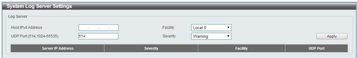
Figure 5-11 System Log Server Settings window
The fields that can be configured are described below:
| Parameter | Description |
| Host IPv4 Address | Enter the system log server's IPv4 address here. |
| UDP Port | Enter the system log server's UDP port number here. This value must be between 1024 and 65535. By default, this value is 514. |
| Facility | Specifies an application from which system logs are sent to the remote server. Only one facility can be assigned to a single server. If a second facility level is assigned, the first facility is overwritten. There are up to eight facilities can be assigned (Local 0 to Local 7). |
| Severity | Select the severity value of the type of information that will be logged. Options to choose from are Warning, informational, and AllThe possible levels are:Warning - The lowest level of a device warning. The device is functioning, but an operational problem has occurred.Informational - Provides device information.All - Displays all levels of system logs. |
Click the Apply button to accept the changes made.
System Log
This window is used to view and clear the system log.
To view the following window, click System > System Log > System Log, as shown below:
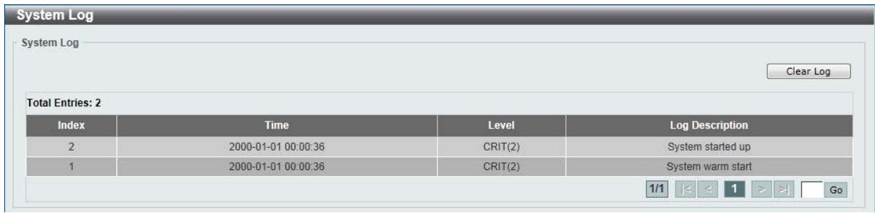
Figure 5-12 System Log window
Click the Clear Log button to clear the system log entries displayed in the table.
Enter a page number and click the Go button to navigate to a specific page when multiple pages exist.
Time
The Simple Network Time Protocol (SNTP) is a protocol for synchronizing computer clocks through the Internet. It provides comprehensive mechanisms to access national time and frequency dissemination services, organize the SNTP subnet of servers and clients, and adjust the system clock in each participant.
Clock Settings
This window is used to configure the time settings for the Switch.
To view the following window, click System > Time > Clock Settings, as shown below:
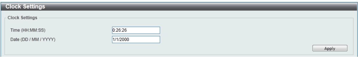
Figure 5-13 Clock Settings window
The fields that can be configured are described below:
| Parameter | Description |
| Time (HH:MM:SS) | Enter the current time in hours, minutes, and seconds. |
| Date (DD / MM / YYYY) | Enter the current day, month, and year to update the system clock. |
Click the Apply button to accept the changes made.
Time Zone Settings
This window is used to configure time zones and Daylight Savings Time settings for SNMP.
To view the following window, click System > Time > Time Zone Settings, as shown below:
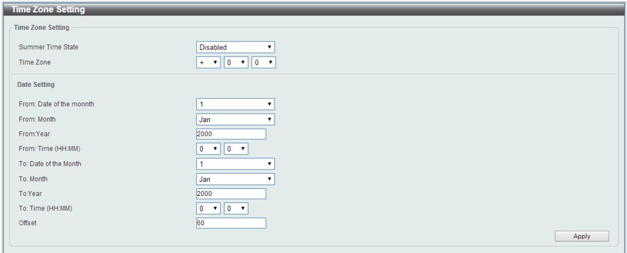
Figure 5-14 Time Zone Settings window
The fields that can be configured are described below:
| Parameter | Description |
| Summer Time State | Select the summer time setting. Options to choose from are Disabled, and Date Setting. Disabled - Select to disable the summer time setting. Date Setting - Select to configure the summer time that should start and end on the specified date. |
| Time Zone | Select to specify your local time zone's offset from Coordinated Universal Time (UTC). |
The fields that can be configured for Date Setting are described below:
| Parameter | Description |
| From: Date of the Month | Select date of the month that summer time will start. |
| From: Month | Select the month that summer time will start. |
| From: Year | Enter the year that the summer time will start. |
| From: Time (HH:MM) | Select the time of the day that summer time will start. |
| To: Date of the Month | Select date of the month that summer time will end. |
| To: Month | Select the month that summer time will end. |
| To: Year | Enter the year that the summer time will end. |
| To: Time (HH:MM) | Select the time of the day that summer time will end. |
| Offset | Enter the number of minutes to add during summer time. The default value is 60. The range of this offset is 30, 60, 90 and 120. |
Click the Apply button to accept the changes made.
SNTP Settings
This window is used to configure the time settings for the Switch.
To view the following window, click System > Time > SNMP Settings, as shown below:
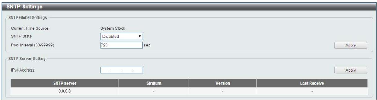
Figure 5-15SNTP Settings window
The fields that can be configured for SNTP Global Settings are described below:
| Parameter | Description |
| SNTP State | Select this option to enable or disable SNTP. |
| Pool Interval | Enter the synchronizing interval in seconds. The value is from 30 to 99999 seconds. The default interval is 720 seconds. |
Click the Apply button to accept the changes made.
The fields that can be configured for SNMP Server Setting are described below:
| Parameter | Description |
| IPv4 Address | Enter the IP address of the SNMP server which provides the clock synchronization. |
Click the Apply button to add the SNMP server.
Click the Delete button to remove the specified entry.
Time Profile
This window is used to view and configure the time range settings. The maximum number of time profiles supported by the switch is 4.
To view the following window, click System > Time Profile, as shown below:
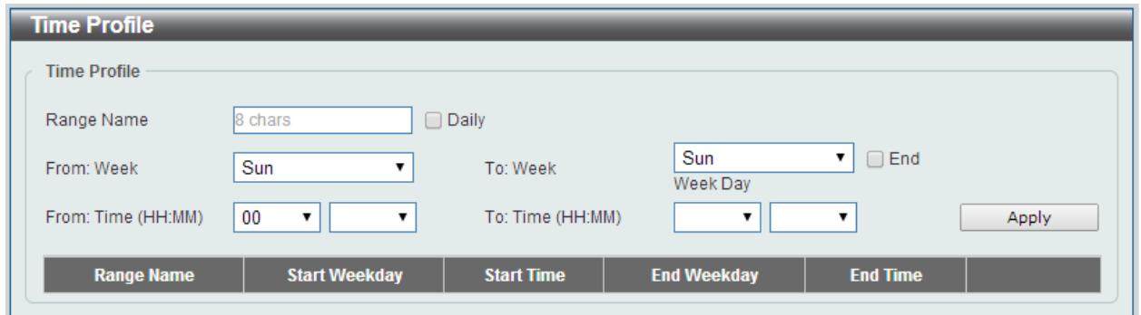
Figure 5-16 Time Range window
The fields that can be configured are described below:
| Parameter | Description |
| Range Name | Enter the name of the time range. This name can be up to 8 characters long. |
| From Week / To Week | Select the starting and ending days of the week that will be used for this time range. Tick the Daily option to use this time range for every day of the week. Tick the End Week Day option to use this time range from the starting day of the week until the end of the week, which is Sunday. |
| From Time / To Time | Select the starting and ending time of the day that will be used for this time range. The first drop-down menu selects the hour and the second drop-down menu selects the minute. |
Click the Apply button to accept the changes made.
Click the Delete button to remove the specified entry.
6. Management
User Account Settings
SNMP
HTTP/HTTPS
D-Link Discovery Protocol
User Account Settings
This window is used to configure the user accounts. The active user account sessions can be viewed.
There are several configuration options available in the Web User Interface (Web UI). The set of configuration options available to the user depends on the account's Privilege Level.

NOTE: By default, the admin account is created on the Switch.
To view the following window, click Management > User Account Settings, as shown below:
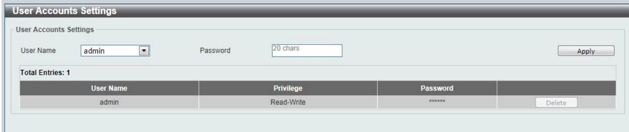
Figure 6-1 User Management Settings window
The fields that can be configured are described below:
| Parameter | Description |
| User Name | Select the user account name here. |
| Password | Enter the password for the account here. |
Click the Apply button to accept the changes made.
Click the Delete button to remove the specified user account entry.
Note: Only one user can be logged into the switch at any time.
SNMP
Simple Network Management Protocol (SNMP) is an OSI Layer 7 (Application Layer) designed specifically for managing and monitoring network devices. SNMP enables network management stations to read and modify the settings of gateways, routers, switches, and other network devices. Use SNMP to configure system features for proper operation, monitor performance and detect potential problems in the Switch, switch group or network.
Managed devices that support SNMP include software (referred to as an agent), which runs locally on the device. A defined set of variables (managed objects) is maintained by the SNMP agent and used to manage the device. These objects are defined in a Management Information Base (MIB), which provides a standard presentation of the information controlled by the on-board SNMP agent. SNMP defines both the format of the MIB specifications and the protocol used to access this information over the network.
The Switch supports the SNMP versions 1, and 2c. The two versions of SNMP vary in the level of security provided between the management station and the network device.
In SNMP v.1 and v2c, user authentication is accomplished using 'community string', which function like passwords. The remote user SNMP application and the Switch SNMP must use the same community string. SNMP packets from any station that has not been authenticated are ignored (dropped).
Traps
Traps are messages that alert network personnel of events that occur on the Switch. The events can be as serious as a reboot (someone accidentally turned OFF the Switch), or less serious like a port status change. The Switch generates traps and sends them to the trap recipient (or network manager). Typical traps include trap messages for Authentication Failure, and Topology Change.
MIBs
The Switch in the Management Information Base (MIB) stores management and counter information. The Switch uses the standard MIB-II Management Information Base module. Consequently, values for MIB objects can be retrieved from any SNMP-based network management software. In addition to the standard MIB-II, the Switch also supports its own proprietary enterprise MIB as an extended Management Information Base. Specifying the MIB Object Identifier may also retrieve the proprietary MIB. MIB values can be either read-only or read-write.
The Switch supports the Simple Network Management Protocol (SNMP) versions 1, and 2c. The administrator can specify the SNMP version used to monitor and control the Switch.
SNMP settings are configured using the menus located on the SNMP folder of the Web manager. Workstations on the network that are allowed SNMP privileged access to the Switch can be restricted with the Management Station IP Address menu.
SNMP Global Settings
This window is used to configure the SNMP global settings and trap settings.
To view the following window, click Management > SNMP > SNMP Global Settings, as shown below:
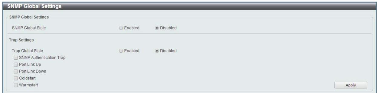
Figure 6-2 SNMP Global Settings window
The fields that can be configured for SNMP Global Settings are described below:
| Parameter | Description |
| SNMP Global State | Select this option to enable or disable the SNMP feature. |
The fields that can be configured for Trap Settings are described below:
| Parameter | Description |
| Trap Global State | Select this option to enable or disable the sending of all or specific SNMP notifications. |
| SNMP Authentication Trap | Tick this option to control the sending of SNMP authentication failure notifications. |
| Port Link Up | Tick this option to control the sending of port link up notifications. |
| Port Link Down | Tick this option to control the sending of port link down notifications. |
| Coldstart | Tick this option to control the sending of SNMP ColdStart notifications. |
| Warmstart | Tick this option to control the sending of SNMP WarmStart notifications. |
Click the Apply button to accept the changes made.
SNMP Community Table Settings
This window is used to create an SNMP community string to define the relationship between the SNMP manager and an agent. The community string acts like a password to permit access to the agent on the Switch. One or more of the following characteristics can be associated with the community string:
- Read/write or read-only level permission for the MIB objects accessible to the SNMP community.
To view the following window, click Management > SNMP > SNMP Community Table Settings, as shown below:
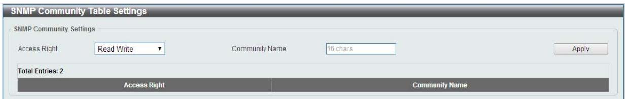
Figure 6-3 SNMP Community Table Settings window
The fields that can be configured are described below:
| Parameter | Description |
| Access Right | Select the access right here. Options to choose from are Read Only, and Read Write. Read Only - SNMP community members using the community string created can only read the contents of the MIBs on the Switch. Read Write - SNMP community members using the community string created can read from, and write to the contents of the MIBs on the Switch. |
| Community Name | Enter an alphanumeric string of up to 16 characters that is used to identify members of an SNMP community. This string is used like a password to give remote SNMP managers access to MIB objects in the Switch's SNMP agent. |
Click the Apply button to accept the changes made.
SNMP Host Table Settings
This window is used to configure and display the recipient of the SNMP notification.
To view the following window, click Management > SNMP > SNMP Host Table Settings, as shown below:
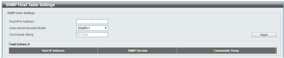
Figure 6-4 SNMP Host Table Settings
The fields that can be configured are described below:
| Parameter | Description |
| Host IPv4 Address | Enter the IPv4 address of the SNMP notification host. |
| User-based Security Model | Select the security model here. Options to choose from are SNMPv1, and SNMPv2c. SNMPv1 - Select to allow the group user to use the SNMPv1 security model. SNMPv2c - Select to allow the group user to use the SNMPv2c security model. |
| Community String | Enter the community string to be sent with the notification packet. |
Click the Apply button to accept the changes made.
HTTP/HTTPS
This window is used to configure Web settings on the Switch.
To view the following window, click Management > HTTP/HTTPS, as shown below:
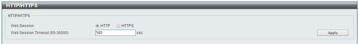
Figure 6-5 HTTP/HTTPS window
The fields that can be configured for HTTP/HTTPS Settings are described below:
| Parameter | Description |
| Web Session | Select this option to enable the configuration through HTTP or HTTPS. |
| Note: When switching from HTTP to HTTPS mode, the switch will take about 30 seconds to initialize the secured HTTP environment. | |
| Web Session Timeout | Enter a value for the amount of time in seconds before the web session expires. |
Click the Apply button to accept the changes made.
Note: If the switch is in HTTPS mode, the firmware or configuration cannot be upgraded using regular HTTP.
D-Link Discovery Protocol
This window is used to configure and display D-Link Discovery Protocol (DDP).
To view the following window, click Management > D-Link Discovery Protocol, as shown below:
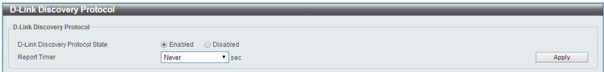
Figure 6-6 D-Link Discovery Protocol window
The fields that can be configured for D-Link Discovery Protocol are described below:
| Parameter | Description |
| D-Link Discovery Protocol State | Select this option to enable or disable DDP global state. |
| Report Timer | Select the interval in seconds between two consecutive DDP report messages. Options to choose from are 30, 60, 90,120, and Never. |
Click the Apply button to accept the changes made.
7. Layer 2 Features
FDB
VLAN
Spanning Tree
Loopback Detection
Link Aggregation
L2 Multicast Control
LLDP
FDB
Static FDB
Unicast Static FDB
This window is used to view and configure the static unicast forwarding settings on the Switch.
To view the following window, click L2 Features > FDB > Static FDB > Unicast Static FDB, as shown below:
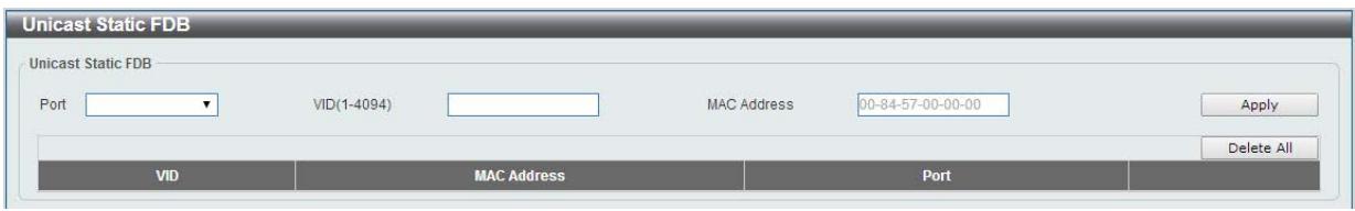
Figure 7-1 Unicast Static FDB window
The fields that can be configured are described below:
| Parameter | Description |
| Port | Allows the selection of the port number on which the MAC address entered resides. |
| VID | Enter the VLAN ID on which the associated unicast MAC address resides. |
| MAC Address | Enter the MAC address to which packets will be statically forwarded or dropped. This must be a unicast MAC address. |
Click the Apply button to accept the changes made.
Click the Delete All button to delete all the entries found in the display table.
Click the Delete button to remove the specified entry.
Multicast Static FDB
This window is used to view and configure the multicast static FDB settings. To view the following window, click L2 Features > FDB > Static FDB > Multicast Static FDB, as shown below:
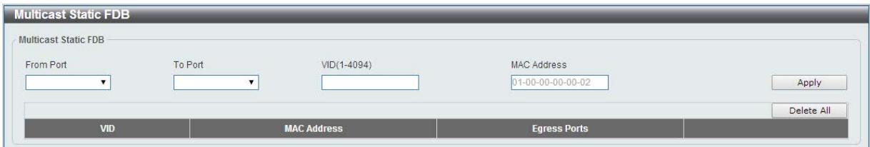
Figure 7-2 Multicast Static FDB window
The fields that can be configured are described below:
| Parameter | Description |
| From Port / To Port | Select the appropriate port range used for the configuration here. |
| VID | Enter the VLAN ID of the VLAN the corresponding MAC address belongs to. |
| MAC Address | Enter the static destination MAC address of the multicast packets. This must be a multicast MAC address. The format of the destination MAC address is 01-XX-XX-XX-XX-XX. |
Click the Apply button to accept the changes made.
Click the Delete All button to remove all the entries.
Click the Delete button to remove the specific entry.
MAC Address Table Settings
This window is used to view and configure the MAC address table's global settings.
To view the following window, click L2 Features > FDB > MAC Address Table Settings, as shown below:
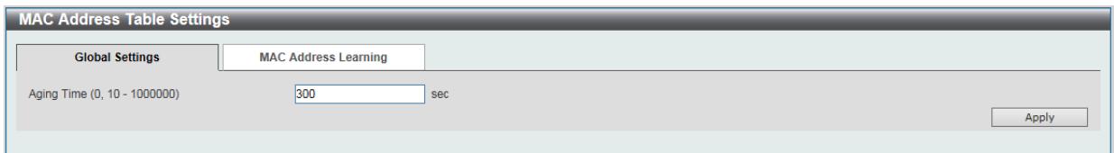
Figure 7-3 MAC Address Table Settings (Global Settings) window
The fields that can be configured are described below:
| Parameter | Description |
| Aging Time | Enter the MAC address table's aging time value here. This value must be between 10 and 1000000 seconds. Entering 0 will disable MAC address aging. By default, this value is 300 seconds. |
Click the Apply button to accept the changes made.
After clicking the MAC Address Learning tab, at the top of the page, the following page will be available.
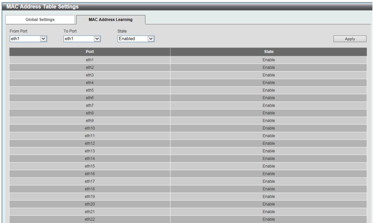
Figure 7-4 MAC Address Table Settings (MAC Address Learning) window
The fields that can be configured are described below:
| Parameter | Description |
| From Port / To Port | Select the range of ports that will be used for this configuration here. |
| State | Select to enable or disable the MAC address learning function on the ports specified here. |
Click the Apply button to accept the changes made.
MAC Address Table
This window is used to view the entries listed in the MAC address table.
To view the following window, click L2 Features > FDB > MAC Address Table, as shown below:
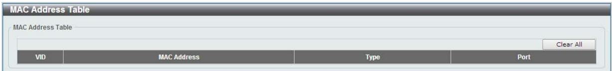
Figure 7-5 MAC Address Table window
Click the Clear All button to clear all dynamic MAC addresses.
VLAN
802.1Q VLAN
This window is used to view and configure the VLAN settings on this switch.
To view the following window, click L2 Features > VLAN > 802.1Q VLAN, as shown below:
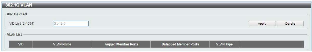
Figure 7-6 802.1Q VLAN window
The fields that can be configured for 802.1Q VLAN are described below:
| Parameter | Description |
| VID List | Enter the VLAN ID list that will be created here. |
Click the Apply button to accept the changes made.
Click the Edit button to re-configure the specific entry.
Click the Delete button to remove the specific entry.
Enter a page number and click the Go button to navigate to a specific page when multiple pages exist.
Port-based VLAN
This window is used to configure the asymmetric VLAN function.
To view the following window, click L2 Features > VLAN > Port-based VLAN, as shown below:
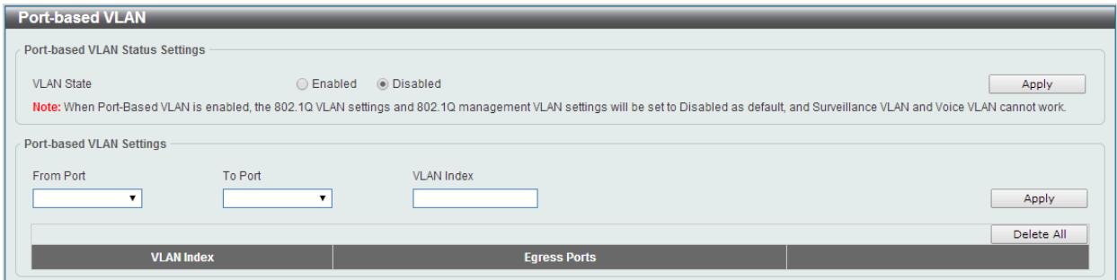
Figure 7-7 Asymmetric VLAN window
The fields that can be configured are described below:
| Parameter | Description |
| VLAN State | Select this option to enable or disable the Port-based VLAN function. |
| From Port / To Port | Select the range of ports that will be used for this configuration here. |
| VLAN Index | VLAN Index is a unique number that identifies a particular VLAN |
Click the Apply button to accept the changes made.
Click the Delete All button to delete all the entries found in the display table.
Management VLAN
This window is used to configure the asymmetric VLAN function.
To view the following window, click L2 Features > VLAN > Management VLAN, as shown below:
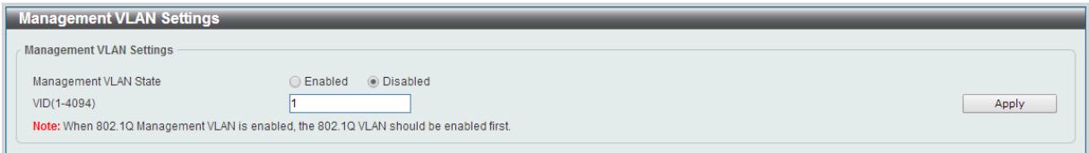
Figure 7-8 Asymmetric VLAN window
The fields that can be configured are described below:
| Parameter | Description |
| Management VLAN State | Select this option to enable or disable the Management VLAN function. |
| VID | VLAN VID is a unique number (between 1 and 4094) that identifies a particular VLAN. |
Click the Apply button to accept the changes made.
Asymmetric VLAN
This window is used to configure the asymmetric VLAN function.
To view the following window, click L2 Features > VLAN > Asymmetric VLAN, as shown below:
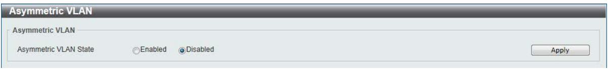
Figure 7-9 Asymmetric VLAN window
The fields that can be configured are described below:
| Parameter | Description |
| Asymmetric VLAN State | Select this option to enable or disable the asymmetric VLAN function |
Click the Apply button to accept the changes made.
VLAN Interface
This window is used to view and configure VLAN interface settings.
To view the following window, click L2 Features > VLAN > VLAN Interface, as shown below:
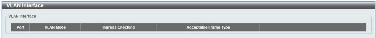
Figure 7-10 VLAN Interface window
Click the View Detail button to view more detailed information about the VLAN on the specific interface.
Click the Edit button to re-configure the specific entry.
After clicking the VLAN Detail button, the following page will appear.
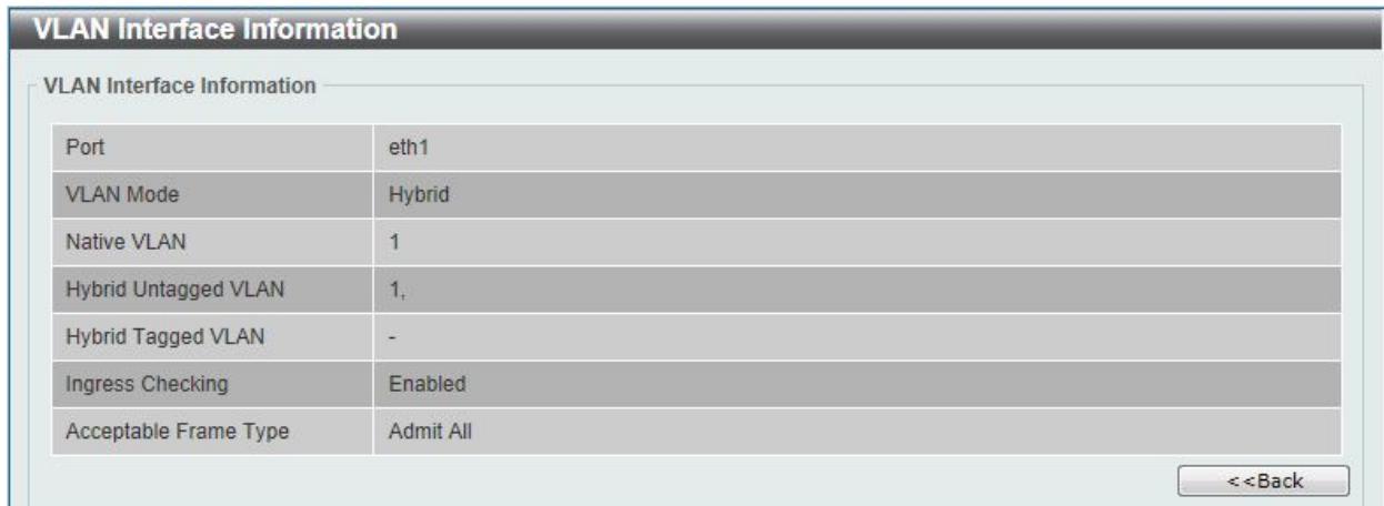
Figure 7-11 VLAN Interface Information window
More detailed information about the VLAN of the specific interface is displayed.
Click the Back button to return to the previous window.
After click the Edit button, the following window will appear. This is a dynamic window that will change when a different VLAN Mode was selected. When Access was selected as the VLAN Mode, the following page will appear.
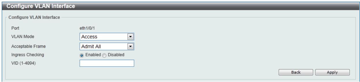
Figure 7-12 Configure VLAN Interface - Access window
The fields that can be configured are described below:
| Parameter | Description |
| VLAN Mode | Select the VLAN mode option here. Options to choose from are Access, Hybrid, and Trunk. |
| Acceptable Frame | Select the acceptable frame behavior option here. Options to choose from are Tagged Only, Untagged Only, and Admit All. |
| Ingress Checking | Select this option to enable or disable the ingress checking function. |
| VID | Enter the VLAN ID used for this configuration here. This value must be between 1 and 4094. |
Click the Apply button to accept the changes made.
Click the Back button to return to the previous window.
When Hybrid was selected as the VLAN Mode, the following page will appear.
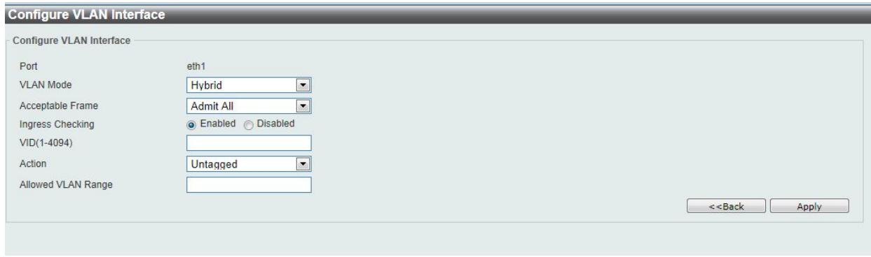
Figure 7-13 Configure VLAN Interface - Hybrid window
The fields that can be configured are described below:
| Parameter | Description |
| VLAN Mode | Select the VLAN mode option here. Options to choose from are Access, Hybrid, and Trunk. |
| Acceptable Frame | Select the acceptable frame behavior option here. Options to choose from are Tagged Only, Untagged Only, and Admit All. |
| Ingress Checking | Select the check box to enable or disable the ingress checking function. |
| VID | Enter the VLAN ID used for this configuration here. This value must be between 1 and 4094. |
| Action | Select the action that will be taken here. Options to choose from are Remove, Tagged, and Untagged. |
| Allowed VLAN Range | Enter the allowed VLAN range information here. |
Click the Apply button to accept the changes made.
Click the Back button to return to the previous window.
When Trunk is selected as the VLAN Mode, the following page will appear.
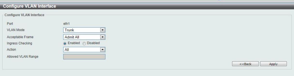
Figure 7-14 Configure VLAN Interface - Trunk window
The fields that can be configured are described below:
| Parameter | Description |
| VLAN Mode | Select the VLAN mode option here. Options to choose from are Access, Hybrid, and Trunk. |
| Acceptable Frame | Select the acceptable frame behavior option here. Options to choose from are Tagged Only, Untagged Only, and Admit All. |
| Ingress Checking | After selecting Trunk as the VLAN Mode the following parameter will be available. Select to enable or disable the ingress checking function. |
| Action | Select the action that will be taken here. Options to choose from are Remove, Tagged, and Untagged. |
| Allowed VLAN Range | Enter the allowed VLAN range information here. |
Click the Apply button to accept the changes made.
Click the Back button to return to the previous window.
Auto Surveillance VLAN
Auto Surveillance Properties
This window is used to configure the auto surveillance VLAN global settings and display the ports surveillance VLAN information.
To view the following window, click L2 Features > VLAN > Auto Surveillance VLAN > Auto Surveillance Properties, as shown below:
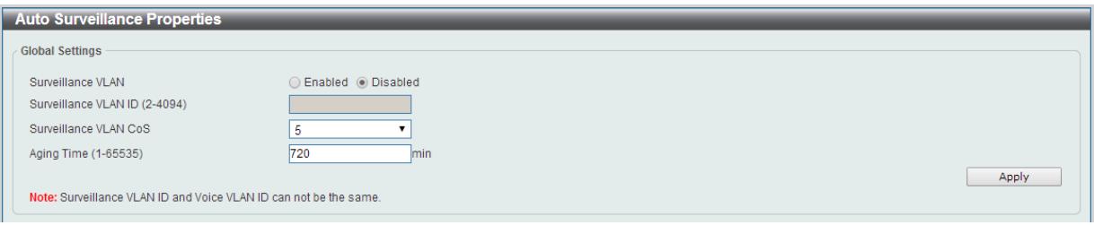
Figure 7-15 Auto Surveillance Properties window
The fields that can be configured for Global Settings are described below:
| Parameter | Description |
| Surveillance VLAN | Select this option to enable or disable the surveillance VLAN state |
| Surveillance VLAN ID | Enter the surveillance VLAN ID. The range is from 2 to 4094. |
| Surveillance VLAN CoS | Select the priority of the surveillance VLAN from 0 to 7. |
| Aging Time | Enter the aging time of surveillance VLAN. The range is from 1 to 65535 minutes. The default value is 720 minutes. The aging time is used to remove a port from surveillance VLAN if the port is an automatic surveillance VLAN member. When the last surveillance device stops sending traffic and the MAC address of this surveillance device is aged out, the surveillance VLAN aging timer will be started. The port will be removed from the surveillance VLAN after expiration of surveillance VLAN aging timer. If the surveillance traffic resumes during the aging time, the aging timer will be reset and stop. |
Click the Apply button to accept the changes made.
MAC Settings and Surveillance Device
This window is used to configure the user-defined surveillance device OUI and display the surveillance VLAN information.
To view the following window, click L2 Features > VLAN > Auto Surveillance VLAN > MAC Settings and Surveillance Device, as shown below:
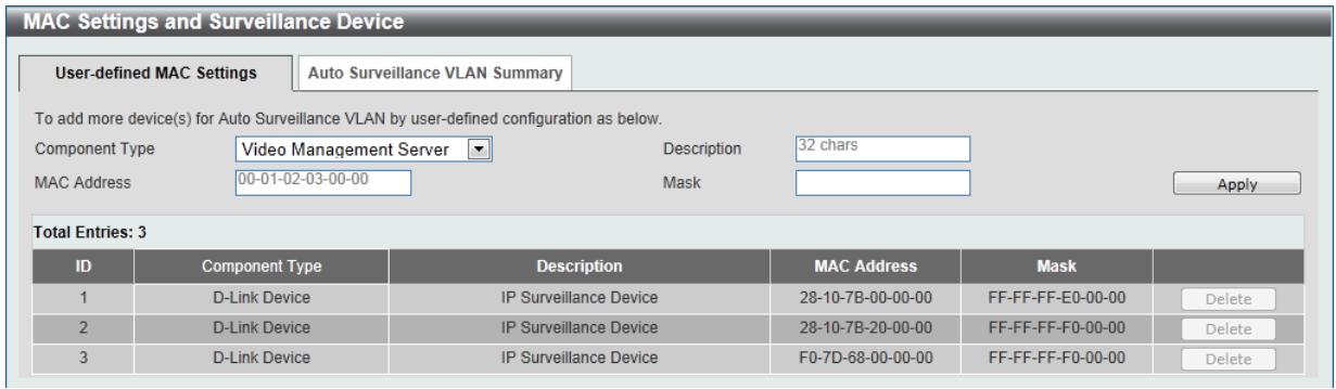
Figure 7-16 User -defined MAC Settings window
The fields that can be configured are described below:
| Parameter | Description |
| Component Type | Select the surveillance component type. Options to choose from are Video Management Server, VMS Client/Remote Viewer, Video Encoder, Network Storage, and Other IP Surveillance Device. |
| Description | Enter the description for the user-defined OUI with a maximum of 8 characters. |
| MAC Address | Enter the OUI MAC address. |
| Mask | Enter the OUI MAC address matching bitmask. |
Click the Apply button to accept the changes made.
Click the Delete button to remove the specified entry.
After clicking the Auto Surveillance VLAN Summary tab, the following page will appear.
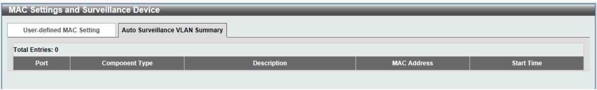
Figure 7-17 Auto Surveillance VLAN Summary window
Voice VLAN
Voice VLAN Global
Voice VLAN is a VLAN used to carry voice traffic from IP phone. Because the sound quality of an IP phone call will be deteriorated if the data is unevenly sent, the quality of service (QoS) for voice traffic shall be configured to ensure the transmission priority of voice packet is higher than normal traffic.
The switches determine whether a received packet is a voice packet by checking its source MAC address. If the source MAC addresses of packets comply with the organizationally unique identifier (OUI) addresses configured by the system, the packets are determined as voice packets and transmitted in voice VLAN.
To view the following window, click L2 Features > VLAN > Voice VLAN > Voice VLAN Global, as show below:
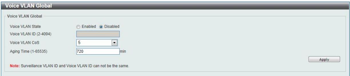
Figure 7-18 Voice VLAN Global window
The fields that can be configured are described below:
| Parameter | Description |
| Voice VLAN State | Select this option to enable or disable the voice VLAN. |
| Voice VLAN ID | Enter the voice VLAN ID. The value is range from 2 to 4094. |
| Voice VLAN CoS | Select the priority of the voice VLAN from 0 to 7. |
| Aging Time | Enter the aging time of surveillance VLAN. The range is from 1 to 65535 minutes. The default value is 720 minutes. The aging time is used to remove a port from voice VLAN if the port is an automatic VLAN member. When the last voice device stops sending traffic and the MAC address of this voice device is aged out, the voice VLAN aging timer will be started. The port will be removed from the voice VLAN after expiration of voice VLAN aging timer. If the voice traffic resumes during the aging time, the aging timer will be reset and stop. |
Click the Apply button to accept the changes made for each individual section.
Voice VLAN Port
This window is used to configure the user-defined voice traffic's port.
To view the following window, click L2 Features > VLAN > Voice VLAN > Voice VLAN OUI, as show below:
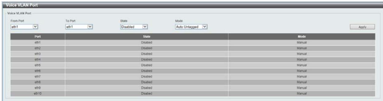
Figure 7-19 Voice VLAN Port window
The fields that can be configured are described below:
| Parameter | Description |
| From Port / To Port | Select the range of ports that will be used for this configuration here. |
| State | Select this option to enable or disable the Voice VLAN state of the port. |
| Mode | Choose the Voice VLAN mode for the port. This can be Auto untagged, Auto Tagged, or Manually configured. |
Click the Apply button to accept the changes made.
Voice VLAN OUI
This window is used to configure the user-defined voice traffic's OUI. The OUI is used to identify the voice traffic. There are a number of pre-defined OUIs. The user can further define the user-defined OUIs if needed. The user-defined OUI cannot be the same as the pre-defined OUI.
To view the following window, click L2 Features > VLAN > Voice VLAN > Voice VLAN OUI, as show below:
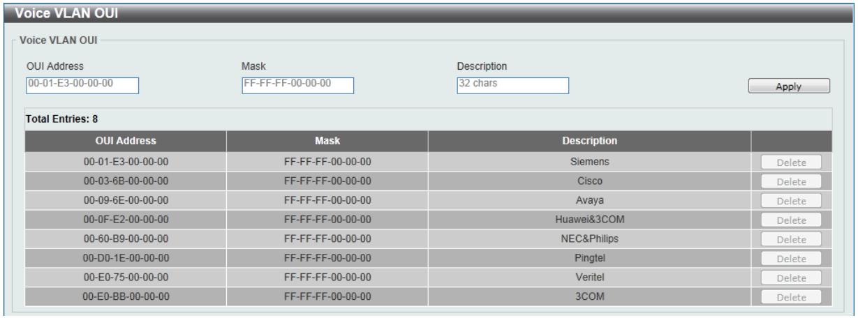
Figure 7-20 Voice VLAN OUI window
The fields that can be configured are described below:
| Parameter | Description |
| OUI Address | Enter the OUI MAC address. |
| Mask | Enter the OUI MAC address matching bitmask. |
| Description | Enter the description for the user-defined OUI with a maximum of 8 characters. |
Click the Apply button to accept the changes made.
Click the Delete button to remove the specified entry.
Voice VLAN Device
This window is used to show voice devices that are connected to the ports. The start time is the time when the device is detected on this port, the activate time is the latest time saw the device sending the traffic.
To view the following window, click L2 Features > VLAN > Voice VLAN > Voice VLAN Device, as show below:
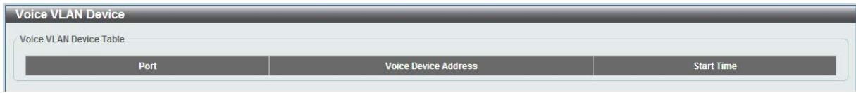
Figure 7-201 Voice VLAN Device window
Spanning Tree
This Switch supports two versions of the Spanning Tree Protocol: 802.1D-1998 STP, 802.1D-2004 Rapid STP. 802.1D-1998 STP will be familiar to most networking professionals. However, since 802.1D-2004 RSTP has been recently introduced to DGS-1100 switches, a brief introduction to the technology is provided below followed by a description of how to set up 802.1D-1998 STP, 802.1D-2004 RSTP.
802.1D-2004 Rapid Spanning Tree
Rapid Spanning Tree Protocol (RSTP) as defined by the IEEE 802.1D-2004 specification and a version compatible with the IEEE 802.1D-1998 STP. RSTP can operate with legacy equipment implementing IEEE 802.1D-1998; however the advantages of using RSTP will be lost.
The IEEE 802.1D-2004 Rapid Spanning Tree Protocol (RSTP) evolved from the 802.1D-1998 STP standard. RSTP was developed in order to overcome some limitations of STP that impede the function of some recent switching innovations, in particular, certain Layer 3 functions that are increasingly handled by Ethernet switches. The basic function and much of the terminology is the same as STP. Most of the settings configured for STP are also used for RSTP. This section introduces some new Spanning Tree concepts and illustrates the main differences between the two protocols.
Edge Port
The edge port is a configurable designation used for a port that is directly connected to a segment where a loop cannot be created. An example would be a port connected directly to a single workstation. Ports that are designated as edge ports transition to a forwarding state immediately without going through the listening and learning states. An edge port loses its status if it receives a BPDU packet, immediately becoming a normal spanning tree port.
Note: If Spanning Tree protocol is used, loopback detection will not be available. If Loopback Detection is enabled, the Spanning Tree protocol will not be available.
STP Global Settings
This window is used to view and configure the STP global settings.
To view the following window, click L2 Features > Spanning Tree > STP Global Settings, as shown below:

Figure 7-212 STP Global Settings window
The field that can be configured for Spanning Tree State is described below:
| Parameter | Description |
| Spanning Tree State | Select this option to enable or disable the STP global state here. |
Click the Apply button to accept the changes made.
The fields that can be configured for Spanning Tree Mode are described below:
| Parameter | Description |
| Spanning Tree Mode | Select the STP mode used here. Options to choose from are RSTP, and STP. |
Click the Apply button to accept the changes made.
The fields that can be configured for STP Traps are described below:
| Parameter | Description |
| STP New Root Trap | Select this option to enable or disable the STP new root trap option here. |
| STP Topology Change Trap | Select this option to enable or disable the STP topology change trap option here. |
Click the Apply button to accept the changes made.
STP Port Settings
This window is used to view and configure the STP port settings.
To view the following window, click L2 Features > Spanning Tree > STP Port Settings, as shown below:
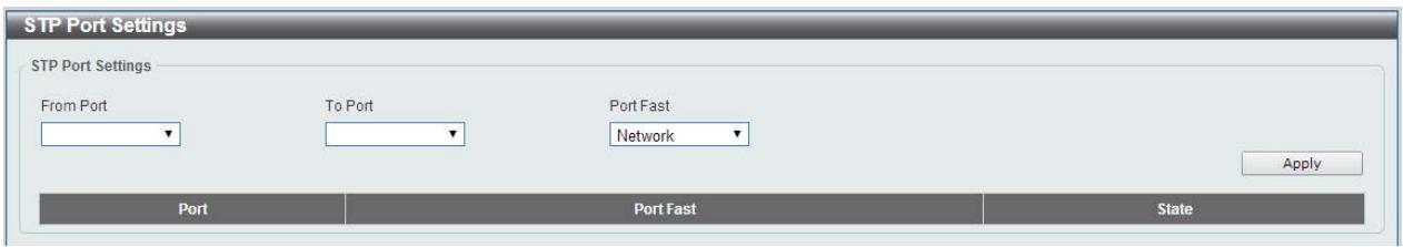
Figure 7-223 STP Port Settings window
The fields that can be configured are described below:
| Parameter | Description |
| From Port / To Port | Select the appropriate port range used for the configuration here. |
| Port Fast | Select the port fast option here. Options to choose from are Network, Disabled, and Edge. In the Network mode the port will remain in the non-port-fast state for three seconds. The port will change to the port-fast state if no BPDU is received and changes to the forwarding state. If the port received the BPDU later, it will change to the non-port-fast state. In the Disable mode, the port will always be in the non-port-fast state. It will always wait for the forward-time delay to change to the forwarding state. In the Edge mode, the port will directly change to the spanning-tree forwarding state when a link-up occurs without waiting for the forward-time delay. If the interface receives a BPDU later, its operation state changes to the non-port-fast state. By default, this option is Edge. |
Click the Apply button to accept the changes made.
Loopback Detection
The Loopback Detection (LBD) function is used to detect the loop created by a specific port. This feature is used to temporarily shut down a port on the Switch when a CTP (Configuration Testing Protocol) packet has been looped back to the Switch. When the Switch detects CTP packets received from a port, this signifies a loop on the network. The Switch will automatically block the port and send an alert to the administrator. The Loopback Detection port will restart (change to normal state) when the Loopback Detection Recover Time times out. The Loopback Detection function can be implemented on a range of ports at a time. The user may enable or disable this function using the drop-down menu.
To view the following window, click L2 Features > Loopback Detection, as shown below:
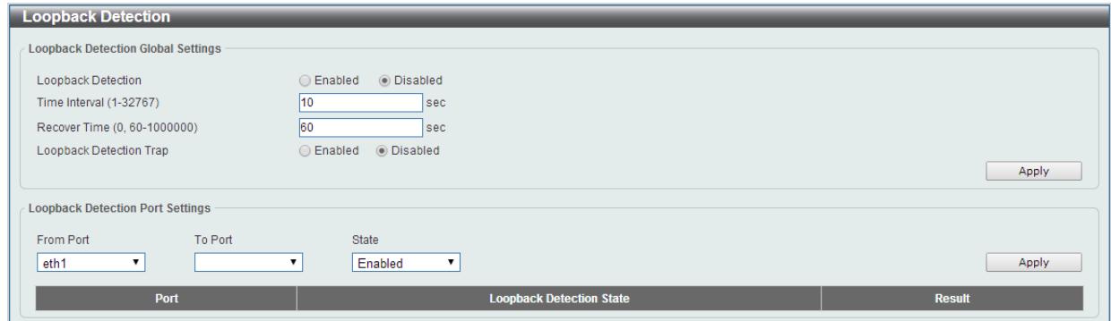
Figure 7-234 Loopback Detection window
The fields that can be configured for Loopback Detection Global Settings are described below:
| Parameter | Description |
| Loopback Detection | Select to enable or disable loopback detection. The default is Disabled. |
| Time Interval | Set a Loop detection Interval between 1 and 32767 seconds. The default is 10 seconds. |
| Recover Time | Time allowed (in seconds) for recovery when a Loopback is detected. The Loop Detection Recover Time can be set at 0 seconds, or 60 to 1000000 seconds. Entering 0 will disable the Loop Detection Recover Time. The default is 60 seconds. |
| Loopback Detection Trap | Select to enable or disable the loopback detection trap state. |
Click the Apply button to accept the changes made.
The fields that can be configured for Loopback Detection Port Settings are described below:
| Parameter | Description |
| From Port / To Port | Select the appropriate port range used for the configuration here. |
| State | Select this option to enable or disable the state of the port. |
Click the Apply button to accept the changes made.
Note: If Spanning Tree protocol is used, loopback detection will not be available. If Loopback Detection is enabled, the Spanning Tree protocol will not be available.
Link Aggregation
Understanding Port Trunk Groups
Port trunk groups are used to combine a number of ports together to make a single high-bandwidth data pipeline.
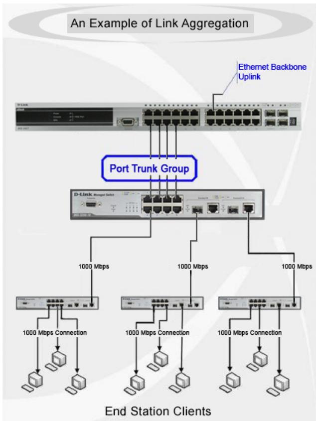
Figure 7-245 Example of Port Trunk Group
The Switch treats all ports in a trunk group as a single port. Data transmitted to a specific host (destination address) will always be transmitted over the same port in a trunk group. This allows packets in a data stream to arrive in the same order they were sent.
Link aggregation allows several ports to be grouped together and to act as a single link. This gives a bandwidth that is a multiple of a single link's bandwidth.
Link aggregation is most commonly used to link a bandwidth intensive network device or devices, such as a server, to the backbone of a network.
All of the ports in the group must be members of the same VLAN, and their STP status, static multicast, traffic control; traffic segmentation and 802.1p default priority configurations must be identical. Further, the LACP aggregated links must all be of the same speed and should be configured as full duplex.
Load balancing is automatically applied to the ports in the aggregated group, and a link failure within the group causes the network traffic to be directed to the remaining links in the group.
The Spanning Tree Protocol will treat a link aggregation group as a single link, on the switch level. On the port level, the STP will use the port parameters of the Master Port in the calculation of port cost and in determining the state of the link aggregation group. If two redundant link aggregation groups are configured on the Switch, STP will block one entire group; in the same way STP will block a single port that has a redundant link.

NOTE: If any ports within the trunk group become disconnected, packets intended for the disconnected port will be load shared among the other linked ports of the link aggregation group.
This window is used to view and configure the link aggregation settings.
To view the following window, click L2 Features > Link Aggregation, as shown below:
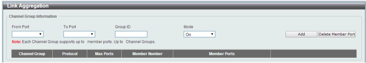
Figure 7-256 Link Aggregation window
The fields that can be configured for Channel Group Information are described below:
| Parameter | Description |
| From Port / To Port | Select the appropriate port range used for the configuration here. |
| Group ID | Enter the channel group number here. The system will automatically create the port-channel when a physical port first joins a channel group. An interface can only join one channel-group. |
| Mode | Select the mode option here. Options to choose from are On, Active, and Passive. If the mode On is specified, the channel group type is static. If the mode Active or Passive is specified, the channel group type is LACP. A channel group can only consist of either static members or LACP members. Once the type of channel group has been determined, other types of interfaces cannot join the channel group. Active - Active LACP ports are capable of processing and sending LACP control frames. This allows LACP compliant devices to negotiate the aggregated link so the group may be changed dynamically as needs require. In order to utilize the ability to change an aggregated port group, that is, to add or subtract ports from the group, at least one of the participating devices must designate LACP ports as active. Both devices must support LACP. Passive - LACP ports that are designated as passive cannot initially send LACP control frames. In order to allow the linked port group to negotiate adjustments and make changes dynamically, one end of the connection must have "active" LACP ports |
Click the Add button to add a new entry based on the information entered.
Click the Delete Member Port button to remove the specific member port.
Click the Delete Channel button to remove the specific entry.
Click the Channel Detail button to view more detailed information about the channel.
After clicking the Channel Detail button, the following page will be available.
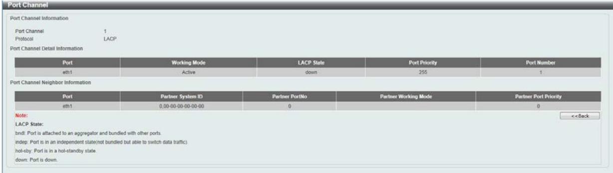
Figure 7-267 Port Channel window
Click the Back button to return to the previous window.
L2 Multicast Control
IGMP Snooping
Internet Group Management Protocol (IGMP) snooping allows the Switch to recognize IGMP queries and reports sent between network stations or devices and an IGMP host.
IGMP Snooping Settings
To view the following window, click L2 Features > L2 Multicast Control > IGMP Snooping > IGMP Snooping Settings, as shown below:
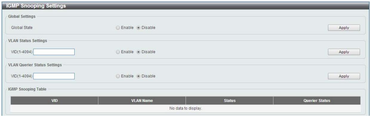
Figure 7-278 IGMP Snooping Settings window
The field that can be configured for Global Settings is described below:
| Parameter | Description |
| Global State | Select this option to enable or disable IGMP snooping global state. |
Click the Apply button to accept the changes made.
The fields that can be configured for VLAN Status Settings are described below:
| Parameter | Description |
| VID | Enter a VLAN ID from 1 to 4094, and select to enable or disable IGMP snooping on the VLAN. |
Click the Apply button to accept the changes made.
The fields that can be configured for VLAN Querier Status Settings are described below:
| Parameter | Description |
| VID | Enter a VLAN ID from 1 to 4094, and select to enable or disable IGMP snooping on the VLAN. |
Enter a page number and click the Go button to navigate to a specific page when multiple pages exist.
IGMP Snooping Groups Settings
This window is used to configure and view the IGMP snooping static group, and view IGMP snooping group.
To view the following window, click L2 Features > L2 Multicast Control > IGMP Snooping > IGMP Snooping Groups Settings, as shown below:
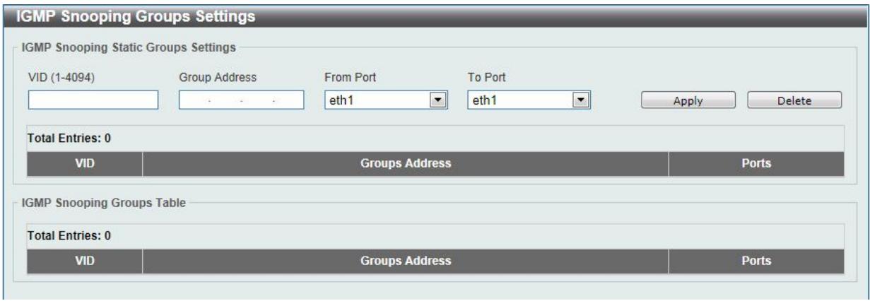
Figure 7-281 IGMP Snooping Groups Settings
The fields that can be configured for IGMP Snooping Static Groups Settings are described below:
| Parameter | Description |
| VID | Enter a VLAN ID of the multicast group. |
| Group Address | Enter an IP multicast group address. |
| From Port / To Port | Select the appropriate port range used for the configuration here. |
Click the Apply button to accept the changes made.
Click the Delete button to remove the specified entry.
Multicast Filtering
This window is used to view and configure the Layer 2 multicast filtering settings.
To view the following window, click L2 Features > L2 Multicast Control > Multicast Filtering, as shown below:

Figure 7-292 Multicast Filtering window
The fields that can be configured are described below:
| Parameter | Description |
| Multicast Filter Mode | Select the multicast filter mode here. Options to choose from are Forward Unregistered, and Filter Unregistered. When selecting the Forward Unregistered option, registered multicast packets will be forwarded based on the forwarding table and all unregistered multicast packets will be flooded based on the VLAN domain. When selecting the Filter Unregistered option, registered packets will be forwarded based on the forwarding table and all unregistered multicast packets will be filtered. |
Click the Apply button to accept the changes made.
LLDP
LLDP Global Settings
LLDP (Link Layer Discovery Protocol) provides IEEE 802.1AB standards-based method for switches to advertise themselves to neighbor devices, as well as to learn about neighbor LLDP devices.
This window is used to configure the LLDP global settings.
To view the following window, click L2 Features > LLDP > LLDP Global Settings, as shown below:
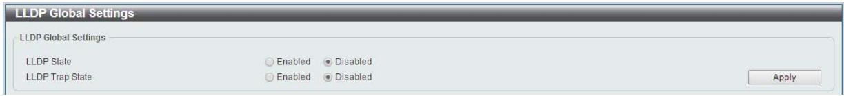
Figure 7-303 LLDP Global Settings window
The fields that can be configured for LLDP Global Settings are described below:
| Parameter | Description |
| LLDP State | Select this option to enable or disable the LLDP feature |
| LLDP Trap State | Select this option to enable or disable the LLDP trap state. |
Click the Apply button to accept the changes made.
LLDP Neighbor Port Information
This window is used to display the information learned from the neighbors. The switch receives packets from a remote station but is able to store the information as local.
To view the following window, click L2 Features > LLDP > LLDP Neighbor Port Information, as show below:

Figure 7-314 LLDP Neighbor Port Information window
8. Quality of Service (QoS)
802.1p Priority
Port Rate Limiting
802.1p Priority
This window is used to view and configure the port's default CoS settings.
To view the following window, click QoS > 802.1p Priority, as shown below:
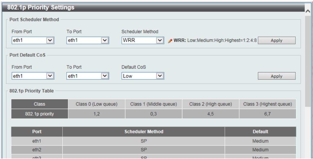
Figure 8-1 Port Default CoS window
The fields that can be configured for Port Scheduler Method are described below:
| Parameter | Description |
| From Port / To Port | Select the appropriate port range used for the configuration here. |
| Scheduler Method | SP - Denoting a Strict Priority scheduling will set the highest queue to be emptied first while the other queues will follow the weighted round-robin scheduling scheme WRR - Use the weighted round-robin ( WRR ) algorithm to handle packets in an even distribution in priority classes of service. |
Click the Apply button to accept the changes made.
The fields that can be configured Port Default CoS are described below:
| Parameter | Description |
| From Port / To Port | Select the appropriate port range used for the configuration here. |
| Default CoS | Select the default CoS option for the port(s) specified here. The priorities are Highest, High, Medium and Low. |
Click the Apply button to accept the changes made.
Port Rate Limiting
This window is used to view and configure the port rate limiting settings.
To view the following window, click QoS > Port Rate Limiting, as shown below:
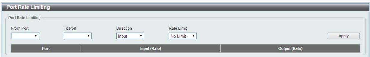
Figure 8-2 Port Rate Limiting window
The fields that can be configured are described below:
| Parameter | Description |
| From Port / To Port | Select the appropriate port range used for the configuration here. |
| Direction | Select the direction option here. Options to choose from are Input and Output. When Input is selected, the rate limit for ingress packets is configured. When Output is selected, the rate limit for egress packets is configured. |
| Rate Limit | Select the rate limit value here. When Direction is Input, this drop-down menu allows you to select data rate from 8Kbps to 512Mbps. When Direction is Output, this drop-down menu allows you to select data rate from 64Kbps to 512Mbps. |
Click the Apply button to accept the changes made.
9. Security
Safeguard Engine
Traffic Segmentation Settings
Storm Control
DoS Attack Prevention Settings
Zone Defense Settings
SSL
Safeguard Engine
D-Link's Safeguard Engine is a robust and innovative technology that automatically throttles the impact of packet flooding into the switch's CPU. This function helps protect the Smart Switch from being interrupted by malicious viruses or worm attacks.
Safeguard Engine Settings
This window is used to view and configure the safeguard engine settings.
To view the following window, click Security > Safeguard Engine > Safeguard Engine Settings, as shown below:
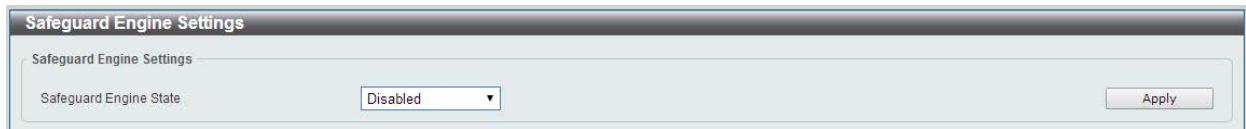
Figure 9-1 Safeguard Engine Settings window
The fields that can be configured for Safeguard Engine Settings are described below:
| Parameter | Description |
| Safeguard Engine State | Select to enable or disable the safeguard engine feature here. |
Traffic Segmentation Settings
This window is used to view and configure the traffic segmentation settings. When the traffic segmentation forwarding domain is specified, packets received by the port will be restricted in Layer 2 packet forwarding to interfaces within the domain. When the forwarding domain of a port is empty, Layer 2 forwarding for packets received by the port is not restricted.
To view the following window, click Security > Traffic Segmentation Settings, as shown below:
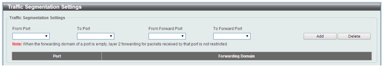
Figure 9-2 Traffic Segmentation Settings window
The fields that can be configured are described below:
| Parameter | Description |
| From Port / To Port | Select the receiving port range used for the configuration here. |
| From Forward Port / To Forward Port | Select the forward port range used for the configuration here. |
Click the Add button to add a new entry based on the information entered.
Click the Delete button to remove an entry based on the information entered.
Storm Control
This window is used to view and configure the storm control settings. Once a packet storm has been detected, the Switch will drop packets coming into the Switch until the storm has subsided.
To view the following window, click Security > Storm Control, as shown below:
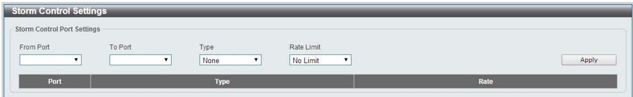
Figure 9-3 Storm Control window
The fields that can be configured for Storm Control Port Settings are described below:
| Parameter | Description |
| From Port / To Port | Select the appropriate port range used for the configuration here. |
| Type | Select the type of storm attack that will be controlled here. Options to choose from are Broadcast, Multicast, and Unicast. |
| Rate Limit | Select a data rate from 512Kbps to 512Mbps. |
Click the Apply button to accept the changes made.
DoS Attack Prevention Settings
This window is used to view and configure the Denial-of-Service (DoS) attack prevention settings. The following well-known DoS types which can be detected by most switches:
- Land Attack: This type of attack involves IP packets where the source and destination address are set to the address of the target device. It may cause the target device to reply to itself continuously.
- Blat Attack: This type of attack will send packets with the TCP/UDP source port equal to the destination port of the target device. It may cause the target device to respond to itself.
- TCP-Null: This type of attack involves port scanning by using specific packets which contain a sequence number of 0 and no flags.
- TCP-Xmas: This type of attack involves port scanning by using specific packets which contain a sequence number of 0 and the Urgent (URG), Push (PSH), and FIN flags.
- TCP SYN-FIN: This type of attack involves port scanning by using specific packets which contain SYN and FIN flags.
- TCP SYN SrcPort Less 1024: This type of attack involves port scanning by using specific packets which contain source port 0 to 1023 and SYN flag.
- Ping of Death Attack: A ping of death is a type of attack on a computer that involves sending a malformed or otherwise a malicious ping to a computer. A ping is normally 64 bytes in size (many computers cannot handle a ping larger than the maximum IP packet size) which is 65535 bytes. The sending of a ping of this size can crash the target computer. Traditionally, this bug has been relatively easy to exploit. Generally, sending a 65536 byte ping packet is illegal according to networking protocol, but a packet of such a size can be sent if it is fragmented; when the target computer reassembles the packet, a buffer overflow can occur, which often causes a system crash.
All Types: All of above types.
To view the following window, click Security > DoS Attack Prevention Settings, as shown below:
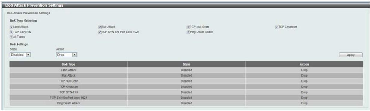
Figure 9-4 DoS Attack Prevention Settings window
The fields that can be configured for DoS Attack Prevention Settings are described below:
| Parameter | Description |
| DoS Type Selection | Tick the DoS type option that will be prevented here. |
| State | Select to enable or disable the DoS attack prevention feature's global state here. |
| Action | Select the action that will be taken when the DoS attack was detected here. The only option to select here is Drop. |
Click the Apply button to accept the changes made.
Zone Defense Settings
This window is used to view and configure the Zone Defense setting.
To view the following window, click Security > Zone Defense Settings, as shown below:

Figure 9-5 Zone Defense Settings window
The fields that can be configured for Zone Defense Settings are described below:
| Parameter | Description |
| State | Select to enable or disable the Zone Defense feature’s global state here. |
Click the Apply button to accept the changes made.
SSL
Secure Sockets Layer (SSL) is a security feature that will provide a secure communication path between a host and client through the use of authentication, digital signatures and encryption.
SSL Global Settings
This window is used to view and configure the SSL feature's global settings.
To view the following window, click Security > SSL > SSL Global Settings, as shown below:

Figure 9-5 SSL Global Settings window
The fields that can be configured for SSL Global Settings are described below:
| Parameter | Description |
| SSL Status | Select to enable or disable the SSL feature's global status here. |
Click the Apply button to accept the changes made.
10. OAM
Cable Diagnostics
Cable Diagnostics
The cable diagnostics feature is designed primarily for administrators or customer service representatives to verify and test copper cables; it can rapidly determine the quality of the cables and the types of error.
To view the following window, click OAM > Cable Diagnostics, as shown below:
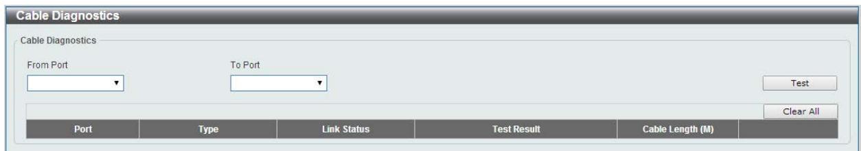
Figure 10-1 Cable Diagnostics window
The fields that can be configured are described below:
| Parameter | Description |
| From Port / To Port | Select the appropriate port range used for the configuration here. |
Click the Test button to test the specific port.
Click the Clear button to clear all the information for the specific port.
Click the Clear All button to clear all the information in this table.
Note: The Cable Diagnostics feature is only supported on the copper ports on all DGS-1100 Series switches.
11. Monitoring
Statistics
Mirror Settings
Statistics
Port Counters
This window is used to display port counter statistics.
To view the following window, click Monitoring > Statistics > Port Counters, as show below:
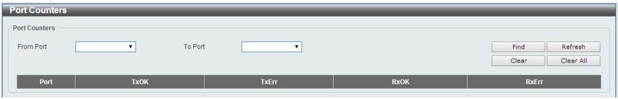
Figure 11-1 Port Counters window
The fields that can be configured are described below:
| Parameter | Description |
| From Port / To Port | Select the appropriate port range used for the configuration here. |
TxOK: Number of packets transmitted successfully.
RxOK: Number of packets received successfully.
TxError: Number of transmitted packets resulting in error.
RxError: Number of received packets resulting in error
Click the Find button to locate a specific entry based on the information entered.
Click the Refresh button to refresh the display table.
Click the Clear button to clear all the information for the specific port.
Click the Clear All button to clear all the information in this table.
Mirror Settings
This window is used to view and configure the mirror feature's settings. The Switch allows users to copy frames transmitted and received on a port and redirect the copies to another port. Attach a monitoring device to the mirroring port, such as a sniffer, to view details about the packets passing through the first port. This is useful for network monitoring and troubleshooting purposes.
To view the following window, click Monitoring > Mirror Settings, as shown below:
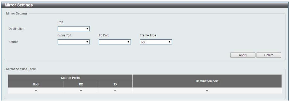
Figure 11-2 Mirror Settings window
The fields that can be configured for Mirror Settings are described below:
| Parameter | Description |
| Destination | Select one destination port from drop-down menu. |
| Source | Select From Port number and the To Port number as source port from drop-down menu. Lastly select the Frame Type option. Options to choose from as the Frame Type are Both, RX, and TX. When selecting Both, traffic in both the incoming and outgoing directions will be mirrored. When selecting RX, traffic in only the incoming direction will be mirrored. When selecting TX, traffic in only the outgoing direction will be mirrored. |
Click the Apply button to accept the changes made.
Click the Delete button to delete an existing mirror entry based on the information entered.
12. Green
Power Saving EEE
Power Saving
This window is used to configure the power saving settings of the Switch.
To view the following window, click Green > Power Saving, as shown below:
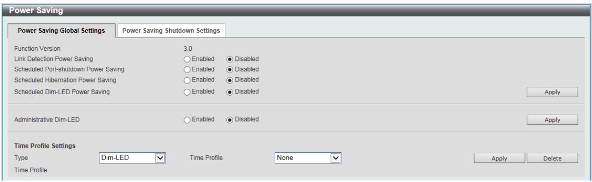
Figure 12-1 Power Saving window
The fields that can be configured are described below:
| Parameter | Description |
| Link Detection Power Saving | Select this option to enable or disable the link detection state. When enabled, a port which has a link down status will be turned off to save power to the Switch. This will not affect the port's capabilities when the port status is link up. |
| Scheduled Port-shutdown Power Saving | Select this option to enable or disable applying the power saving by scheduled port shutdown. |
| Scheduled Hibernation Power Saving | Select this option to enable or disable applying the power saving by scheduled hibernation power. |
| Scheduled Dim-LED Power Saving | Select this option to enable or disable applying the power saving by scheduled dimming LEDs. |
| Administrative Dim-LED | Select this option to enable or disable the port LED function. |
| Type | Select the type of power saving. Option to choose from is Dim-LED or Hibernation. |
| Time Profile | If a Time Profile was previously created, select the desired profile from the drop down list. |
Click the Apply button to accept the changes made for each individual section.
Click the Delete button to remove the specified entry.
After clicking the Power Saving Shutdown Settings tab, the following page will appear.
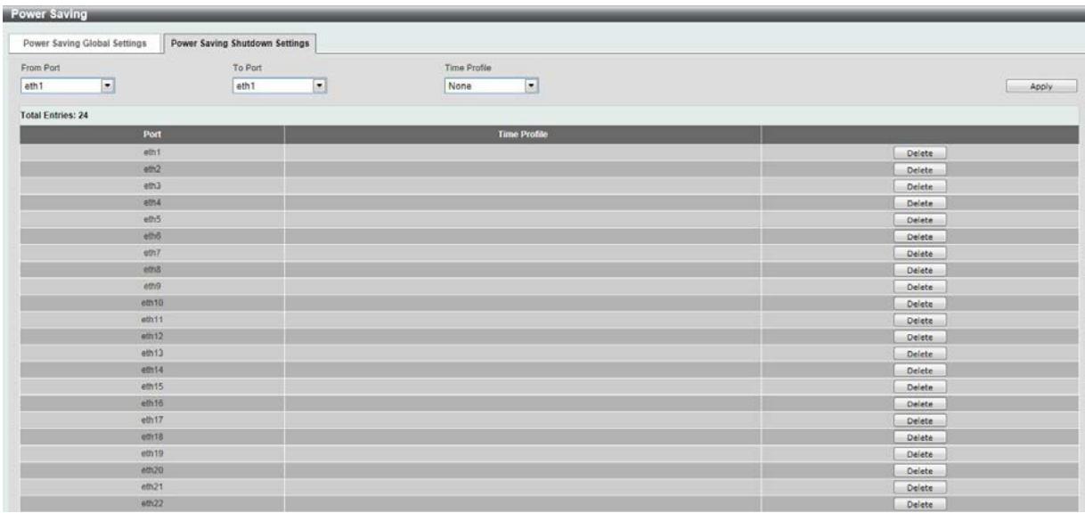
Figure 12-2 Power Saving Shutdown Settings window
The fields that can be configured are described below:
| Parameter | Description |
| From Port / To Port | Select the appropriate port range used for the configuration here. |
| Time Range | If a Time Profile was previously created, select the desired profile from the drop down list. |
Click the Apply button to accept the changes made.
Click the Delete button to remove the specified entry.
EEE
Energy Efficient Ethernet (EEE) is defined in IEEE 802.3az. It is designed to reduce the energy consumption of a link when no packets are being sent.
To view the following window, click Green > EEE, as shown below:
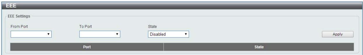
Figure 12-3 EEE window
The fields that can be configured are described below:
| Parameter | Description |
| From Port / To Port | Select the appropriate port range used for the configuration here. |
| State | Select this option to enable or disable the state of this feature here. |
Click the Apply button to accept the changes made.
Note: The EEE feature is only supported on the copper ports on all DGS-1100 Series switches.
13. Save and Tools
Save Configuration
Firmware Upgrade & Backup
Configuration Restore & Backup
Log Backup
Ping
Reset
Reboot System
Save Configuration
This window is used to save the running configuration to the start-up configuration of the Switch.
This is to prevent the loss of configuration in the event of a power failure.
To view the following window, click Save > Save Configuration, as shown below:
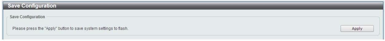
Figure 13-1 Save Configuration window
Click the Apply button to save the configuration to the switch's flash memory.
Firmware Information
This window is used to show firmware information.
To view the following window, click Tools > Firmware Information, as shown below:
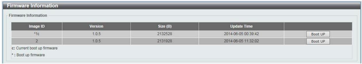
Figure 13-2 Firmware Information window
Boot Up: Clicking the Boot Up button will set that firmware image as the active image to use upon the next system start up.
Note: Changing the firmware only happens after the switch has been manually rebooted. In order to boot with the newly selected firmware, make sure that the switch is rebooted.
Firmware Upgrade & Backup

Note: When upgrading the firmware on the DGS-1100 Series switch, only the image not currently active can be upgraded. All DGS-1100 Series switches come with two images, however only one can be active at any time. (e.g. If image 1 is currently in use, only image 2 can be upgraded, and vice versa.)
Note: If the switch is in HTTPS mode, the firmware or configuration cannot be upgraded using regular HTTP.
Firmware Upgrade from HTTP
This window is used to initiate a firmware upgrade from a local PC using HTTP.
To view the following window, click Tools > Firmware Upgrade & Backup > Firmware Upgrade from HTTP, as shown below:
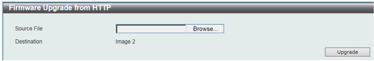
Figure 13-3 Firmware Upgrade from HTTP window
The fields that can be configured are described below:
| Parameter | Description |
| Source File | Enter the source filename and path of the firmware file located on the local PC. Alternatively click the Browse button to navigate to the location of the firmware file located on the local PC. |
Click the Upgrade button to initiate the firmware upgrade.
Firmware Upgrade from TFTP
This window is used to initiate a firmware upgrade from a TFTP server.
To view the following window, click Tools > Firmware Upgrade & Backup > firmware Upgrade from TFTP, as shown below:
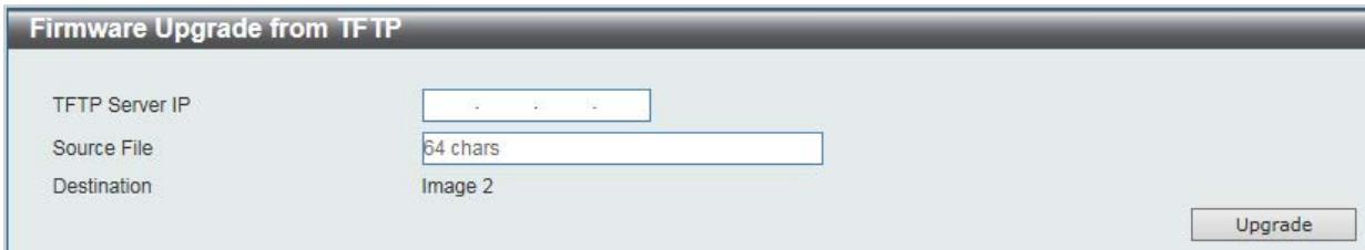
Figure 13-4 Firmware Upgrade from TFTP window
The fields that can be configured are described below:
| Parameter | Description |
| TFTP Server IP | Enter the TFTP server's IPv4 address here. |
| Source File | Enter the source filename and path of the firmware file located on the TFTP server here. |
Click the Upgrade button to initiate the firmware upgrade.
Firmware Backup to HTTP
This window is used to initiate a firmware backup to a local PC using HTTP.
To view the following window, click Tools > Firmware Upgrade & Backup > Firmware Backup to HTTP, as shown below:
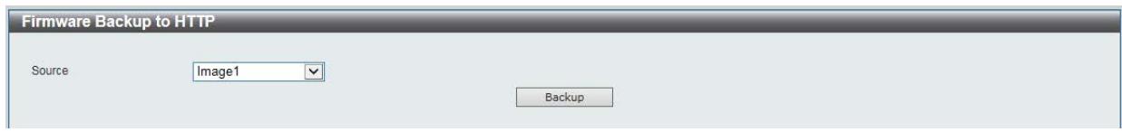
Figure 13-5 Firmware Backup to HTTP window
The fields that can be configured are described below:
| Parameter | Description |
| Source | Select the source image to use for the firmware backup. |
Click the Backup button to initiate the firmware backup.
Firmware Backup to TFTP
This window is used to initiate a firmware backup to a TFTP server.
To view the following window, click Tools > Firmware Upgrade & Backup > Firmware Backup to TFTP, as shown below:
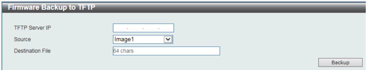
Figure 13-6 Firmware Backup to TFTP window
The fields that can be configured are described below:
| Parameter | Description |
| TFTP Server IP | Enter the TFTP server's IPv4 address here. |
| Source | Select the source image to use for the firmware backup. |
| Destination File | Enter the destination path and location where the firmware file should be stored on the TFTP server. |
Click the Backup button to initiate the firmware backup.
Configuration Restore & Backup
Configuration Restore from HTTP
This window is used to initiate a configuration restore from a local PC using HTTP.
Note: If the switch is in HTTPS mode, the firmware or configuration cannot be upgraded using regular HTTP.
To view the following window, click Tools > Configuration Restore & Backup > Configuration Restore from HTTP, as shown below:
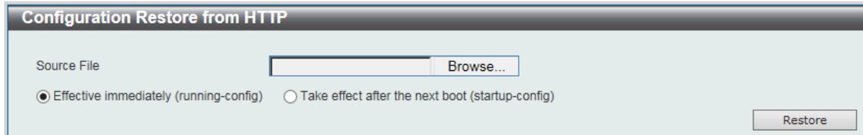
Figure 13-7 Configuration Restore from HTTP window
The fields that can be configured are described below:
| Parameter | Description |
| Source File | Enter the source filename and path of the configuration file located on the local PC. Alternatively click the Browse button to navigate to the location of the configuration file located on the local PC. |
Click the Restore button to initiate the configuration restore.
Click Effective immediately (running-config) to have the uploaded configuration loaded immediately.
Click Take effect after the next boot (startup-config) to load the configuration after the switch has been rebooted.
Configuration Restore from TFTP
This window is used to initiate a configuration restore from a TFTP server.
To view the following window, click Tools > Configuration Restore & Backup > Configuration Restore from TFTP, as shown below:
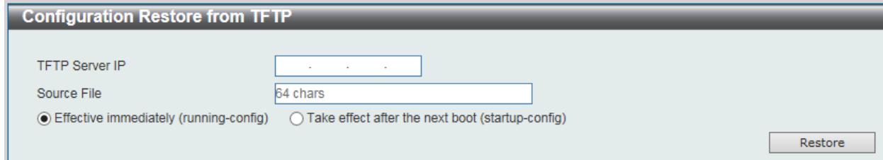
Figure 13-8 Configuration Restore from TFTP window
The fields that can be configured are described below:
| Parameter | Description |
| TFTP Server IP | Enter the TFTP server's IPv4 address here. |
| Source File | Enter the source filename and path of the configuration file located on the TFTP server here. |
Click the Restore button to initiate the configuration restore.
Click Effective immediately (running-config) to have the uploaded configuration loaded immediately.
Click Take effect after the next boot (startup-config) to load the configuration after the switch has been rebooted.
Configuration Backup to HTTP
This window is used to initiate a configuration file backup to a local PC using HTTP.
To view the following window, click Tools > Configuration Restore & Backup > Configuration Backup to HTTP, as shown below:
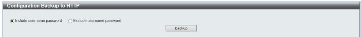
Figure 13-9 Configuration Backup to HTTP window
Select Include username password to save the switch user accounts and passwords to the backup file.
Select Exclude username password to save the switch user accounts and passwords to the backup file.
Click the Backup button to initiate the configuration file backup.
Configuration Backup to TFTP
This window is used to initiate a configuration file backup to a TFTP server.
To view the following window, click Tools > Configuration Restore & Backup > Configuration Backup to TFTP, as shown below:
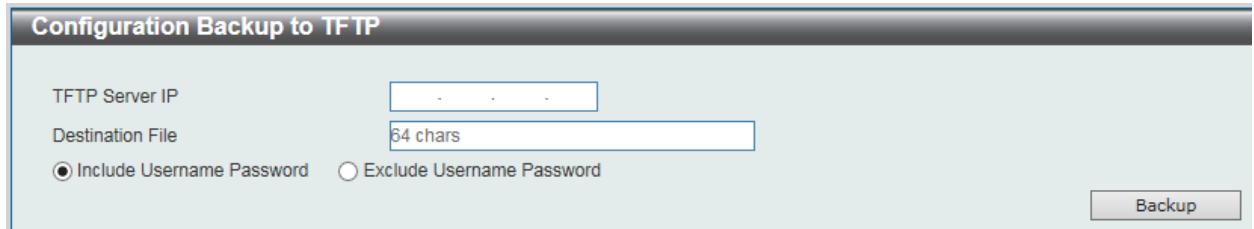
Figure 13-10 Configuration Backup to TFTP window
The fields that can be configured are described below:
| Parameter | Description |
| TFTP Server IP | Enter the TFTP server's IPv4 address here. |
| Destination File | Enter the destination path and location where the configuration file should be stored on the TFTP server. |
Select Include username password to save the switch user accounts and passwords to the backup file.
Select Exclude username password to save the switch user accounts and passwords to the backup file.
Click the Backup button to initiate the configuration file backup.
Log Backup
Log Backup to HTTP
This window is used to initiate a system log backup to a local PC using HTTP.
To view the following window, click Tools > Log Backup > Log Backup to HTTP, as shown below:
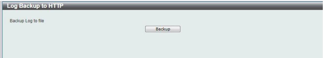
Figure 13-11 Log Backup to HTTP window
Click the Backup button to initiate the system log backup.
Log Backup to TFTP
This window is used to initiate a system log backup to a TFTP server.
To view the following window, click Tools > Log Backup > Log Backup to TFTP, as shown below:
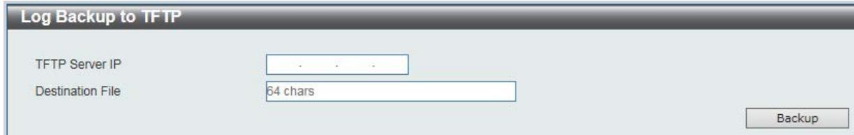
Figure 13-12 Log Backup to TFTP window
The fields that can be configured are described below:
| Parameter | Description |
| TFTP Server IP | Enter the TFTP server's IPv4 address here. |
| Destination File | Enter the destination path and location where the configuration file should be stored on the TFTP server |
Click the Backup button to initiate the system log backup.
Ping
Ping is a small program that sends ICMP Echo packets to the IP address you specify. The destination node then responds to or "echoes" the packets sent from the Switch. This is very useful to verify connectivity between the Switch and other nodes on the network.
To view the following window, click Tools > Ping, as shown below:
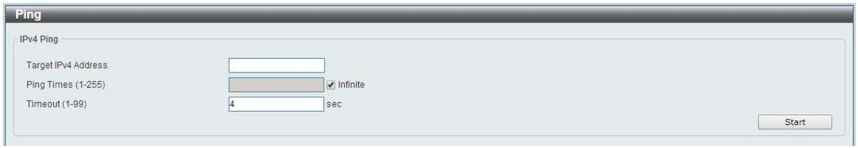
Figure 13-13 Ping window
The fields that can be configured for IPv4 Ping are described below:
| Parameter | Description |
| Target IPv4 Address | Select and enter an IP address to be pinged. |
| Ping Times | Enter the number of times desired to attempt to Ping the IPv4 address configured in this window. Users may enter a number of times between 1 and 255. Tick the Infinite check box to keep sending ICMP Echo packets to the specified IP address until the program is stopped. |
| Timeout | Select a timeout period between 1 and 99 seconds for this Ping message to reach its destination. If the packet fails to find the IP address in this specified time, the Ping packet will be dropped. |
After clicking the Start button in IPv4 Ping section, the following IPv4 Ping Result section will appear:
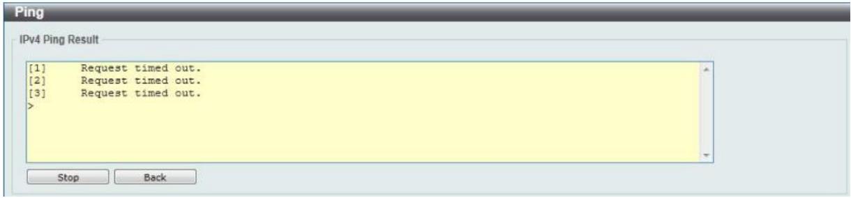
Figure 13-14 Ping - IPv4 Ping Result window
Click the Stop button to halt the Ping Test.
Click the Back button to return to the IPv4 Ping section.
Reset
This window is used to reset the Switch's configuration to the factory default settings.
To view the following window, click Tools > Reset, as shown below:
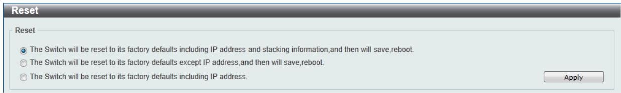
Figure 13-15 Reset window
Select the The Switch will be reset to its factory defaults including IP address and stacking information, and the will save, reboot option to reset the Switch's configuration to its factory default settings.
Select the The Switch will be reset to its factory default except IP address, and then will save, reboot option to reset the Switch's configuration to its factory default settings. This option will exclude the IP address from being changed.
Select the The Switch will be reset to its factory defaults including IP address option to reset the Switch's configuration to its factory default settings.
Click the Apply button to initiate the factory default reset and reboot the Switch.
Reboot System
This window is used to reboot the Switch and alternatively save the configuration before doing so. To view the following window, click Tools > Reboot System, as shown below:
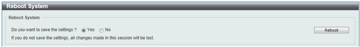
Figure 13-16 Reboot System window
When rebooting the Switch, any configuration changes that was made during this session, will be lost unless the Yes option is selected when asked to save the settings.
Click the Reboot button to alternatively save the settings and reboot the Switch.
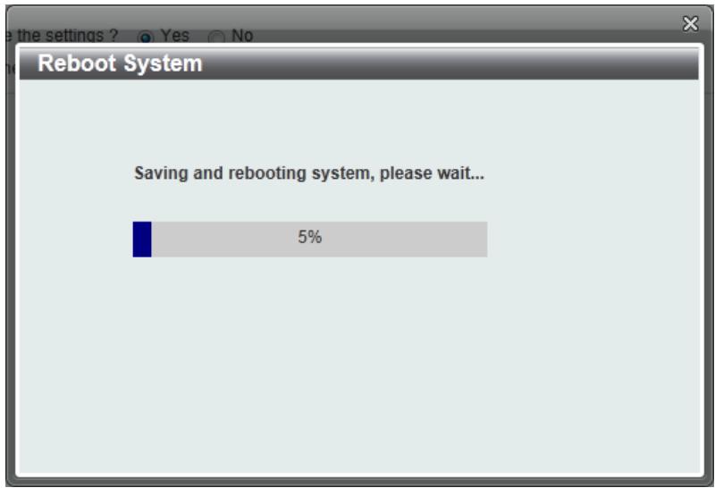
Figure 13-17 Reboot System - Rebooting window
14. Appendix A - Ethernet Technology
This chapter will describe the features of the D-Link DGS-1100 Series Switch and provide some background information about Ethernet/Fast Ethernet/Gigabit Ethernet switching technology.
Gigabit Ethernet Technology
Gigabit Ethernet is an extension of IEEE 802.3 Ethernet utilizing the same packet structure, format, and support for CSMA/CD protocol, full duplex, and management objects, but with a tenfold increase in theoretical throughput of over 100-Mbps Fast Ethernet and a hundredfold increase over 10-Mbps Ethernet. Since it is compatible with all 10-Mbps and 100-Mbps Ethernet environments, Gigabit Ethernet provides a straightforward upgrade without wasting existing investments in hardware, software, or trained personnel.
The increased speed and extra bandwidth offered by Gigabit Ethernet is essential to help solving network bottlenecks that frequently develop as more advanced computer users and newer applications continue to demand greater network resources. Upgrading key components, such as backbone connections and servers to Gigabit Ethernet technology can greatly improve network response times as well as significantly speed up the traffic between subnets.
Gigabit Ethernet enables fast optical fiber connections to support video conferencing, complex imaging, and similar data-intensive applications. Likewise, since data transfers occur 10 times faster than Fast Ethernet, servers outfitted with Gigabit Ethernet NIC's are able to perform 10 times the number of operations in the same amount of time.
In addition, the phenomenal bandwidth delivered by Gigabit Ethernet is the most cost-effective method to take advantage of today and tomorrow's rapidly improving switching and routing internetworking technologies. And with expected advances in the coming years in silicon technology and digital signal processing that will enable Gigabit Ethernet to eventually operate over unshielded twisted-pair (UTP) cabling, outfitting your network with a powerful 1000-Mbps-capable backbone/server connection which will create a flexible foundation for the next generation of network technology products.
Fast Ethernet Technology
The growing importance of LANs and the increasing complexity of desktop computing applications are fueling the need for high performance networks. A number of high-speed LAN technologies have been proposed to provide greater bandwidth and improve client/server response times. Among them, 100BASE-T (Fast Ethernet) provides a non-disruptive, smooth evolution from the current 10BASE-T technology. The non-disruptive and smooth evolution nature, and the dominating potential market base, virtually guarantees cost-effective and high performance Fast Ethernet solutions.
100Mbps Fast Ethernet is a standard specified by the IEEE 802.3 LAN committee. It is an extension of the 10Mbps Ethernet standard with the ability to transmit and receive data at 100Mbps, while maintaining the CSMA/CD Ethernet protocol. Since the 100Mbps Fast Ethernet is compatible with all other 10Mbps Ethernet environments, it provides a straightforward upgrade and utilizes existing investments in hardware, software, and personnel training.
Switching Technology
Another approach to push beyond the limits of Ethernet technology is the development of switching technology. A switch bridges Ethernet packets at the MAC address level of the Ethernet protocol transmitting among connected Ethernet or Fast Ethernet LAN segments.
Switching is a cost-effective way of increasing the total network capacity available to users on a local area network. A switch increases capacity and decreases network loading by dividing a local area network into different segments which won't compete with each other for network transmission capacity.
The switch acts as a high-speed selective bridge between the individual segments. The switch, without interfering with any other segments, automatically forwards traffic that needs to go from one segment to another. By doing this the total network capacity is multiplied, while still maintaining the same network cabling and adapter cards.
15. Appendix B - Technical Specifications
Hardware Specifications
Key Components / Performance
Switching Capacity:
-
DGS-1100-16: 32Gbps
-
DGS-1100-18: 36Gbps
- DGS-1100-24: 48Gbps
- DGS-1100-26 : 52 Gbps
- DGS-1100-24P : 48Gbps
Max. Forwarding Rate:
- DGS-1100-16: 23.81Mpps
- DGS-1100-18: 26.79Mpps
- DGS-1100-24:35.71Mpps
- DGS-1100-26 : 38.69Mpps
- DGS-1100-24P : 35.71Mpps
Forwarding Mode: Store and Forward
Packet Buffer memory:
- DGS-1100-16: 512Kbits
- DGS-1100-18: 1.5Mbits
- DGS-1100-24: 512Kbits
- DGS-1100-26 : 1.5Mbits
- DGS-1100-24P : 512Kbits
Flash Memory: 8M Byte
Port Functions
10/100/1000BaseTX ports compliant with the following standards:
- IEEE 802.3 compliance
- IEEE 802.3u compliance
-
IEEE 802.3ab compliance
-
IEEE802.3at (Only DGS-1100-24 Port 1 ~ Port 12)
-Supports Full/half-Duplex operations at 10/100Mbps
-Supports Full-Duplex operation at 1000Mbps
-Supports IEEE 802.3x Flow Control
-Support Auto-Negotiation
-Compliant to IEEE 802.3az Energy Efficiency Ethernet.
SFP ports compliant with the following standards:
- IEEE 802.3u compliance
- IEEE 802.3z compliance
Physical & Environment
DGS-1100-16/18/24/26/24P: AC input, 100~240 VAC, 50/60Hz, internal universal power supply
Acoustic Value:
- DGS-1100-16/18/24/26: 0dB(A) (Fan-less)
- DGS-1100-26P: 44.5 dB(A)
Operation Temperature 0~50°C
Storage Temperature -10~70°C
Operation Humidity: 10% 95% RH
Storage Humidity: 5% 95% RH
Emission (EMI) Certifications
FCC class A
CE Class A
VCCI Class A
BSMI
CCC
Safety Certifications
CUL, LVD, CB, CCC, BSMI
Features
L2 Features
DGS-1100-16/24/24P: 8K MAC address. DGS-1100-18/26: 16K Mac address
Loopback Detection
Port Mirroring
Link Aggregation
Cable Diagnostics
Spanning Tree
L2 Multicasting
IGMP Snooping
VLAN
802.1Q VLAN standard
Port-Based VLAN
Surveillance VLAN
Voice VLAN:
QoS (Quality of Service)
802.1p priority,
4 queues
Bandwidth Control
Security
Storm Control
DoS Attack Prevention
SSL
D-Link Safeguard
Management
Web-based GUI or D-Link Network Assistant
Configuration backup / restoration via Web-based management
Firmware backup & upgrade via Web-based management
Reset,Reboot system
Factory reset by pressing reset button
SNMP,LLDP,Dual Image,2 level user account,SNTP
Power Saving
IEEE 802.3az Compliant (Energy Efficient Ethernet)
D-Link Green Technologies
- Power saving by link status
- Power Saving by LED Shut-Off:
- Power Saving by Port Shut-Off
- Power Saving by System Hibernation
16. Appendix C - Rack mount Instructions
Safety Instructions - Rack Mount Instructions - The following or similar rack-mount instructions are included with the installation instructions:
A) Elevated Operating Ambient - If installed in a closed or multi-unit rack assembly, the operating ambient temperature of the rack environment may be greater than room ambient. Therefore, consideration should be given to installing the equipment in an environment compatible with the maximum ambient temperature (Tma) specified by the manufacturer.
B) Reduced Air Flow - Installation of the equipment in a rack should be such that the amount of air flow required for safe operation of the equipment is not compromised.
C) Mechanical Loading - Mounting of the equipment in the rack should be such that a hazardous condition is not achieved due to uneven mechanical loading.
D) Circuit Overloading - Consideration should be given to the connection of the equipment to the supply circuit and the effect that overloading of the circuits might have on overcurrent protection and supply wiring. Appropriate consideration of equipment nameplate ratings should be used when addressing this concern.
E) Reliable Earthing - Reliable earthing of rack-mounted equipment should be maintained. Particular attention should be given to supply connections other than direct connections to the branch circuit (e.g. use of power strips)