
BQ1VQ6T012 - Oven SAMSUNG - Free user manual and instructions
Find the device manual for free BQ1VQ6T012 SAMSUNG in PDF.
User questions about BQ1VQ6T012 SAMSUNG
0 question about this device. Answer the ones you know or ask your own.
Ask a new question about this device
Download the instructions for your Oven in PDF format for free! Find your manual BQ1VQ6T012 - SAMSUNG and take your electronic device back in hand. On this page are published all the documents necessary for the use of your device. BQ1VQ6T012 by SAMSUNG.
USER MANUAL BQ1VQ6T012 SAMSUNG
natural_image
Illustration of a standard open oven with digital display and control buttons (no text or symbols)CONTENTS
- Precaution
- Product Specification
- Disassembly and Reassembly
- Troubleshooting
- Exploded Views and Parts List
- PCB Diagrams
- Wiring Diagrams
- Schematic Diagrams
Contents
- Precaution 1
1-1 Safety precautions 1
- Specifications 2
2-1 Features....2
2-2 Specification....3
2-3 Accessory....4
- Disassembly and Reassembly 5
3-1 Tools for Removal and Reassembly. 5
3-2 Replacement of Case upper & Cover back 5
3-3 Replacement the Tube 6
3-4 Replacement of Door Assembly 7
3-5 Replacement of Door Glass 8
3-6 Replacement of the rear oven Lamp Bulb 10
3-7 Replacement of the side Halogen Lamp 10
3-8 Replacement of Assy Control Box 11
3-9 Replacement of Tube Steam Module.... 13
3-10 Replacement of Assy Steam Module 15
3-11 Assembly for Main Assy Steam module part 18
3-12 Replacement of Assy generator sub 20
3-13 Replacement of Motor Fan Cooling 21
3-14 Replacement of Duct Cover, Bracket & Spring Duct & Ceramic Filter 21
3-15 Replacement of Motor Convection.... 22
3-16 Replacement of Heater Convection twin 23
3-17 Replacement of Assy Partition S/W 23
3-18 Replacement of Thermostat 24
3-19 Replacement of Terminal Block 24
3-20 Replacement of Sensor Thermistor 24
3-21 Replacement of Heater Grill.... 25
3-22 Replacement of Heater Bottom 25
3-23 Replacement of Assy PCB Parts (Main PCB) 26
3-24 Replacement of Assy-Door Lock 26
- Troubleshooting....27
4-1 Failure Codes....27
- Exploded Views and Parts List 43
5-1 Exploded Views 43
5-2 Main Parts List 44
5-2 Main Parts List 45
5-3 Door Parts List 46
5-4 Control Parts List 47
5-5 Standard Parts List. 48
- PCB Diagram.... 49
6-1 PCB Diagram 49
- Wiring Diagram 50
7-1 Wiring Diagram 50
- Schematic Diagram.... 51
8-1 Schematic Diagram 51
1. Precaution
Follow these special safety precautions.
1-1 Safety precautions (⚠️)
- All repairs should be done in accordance with the procedures described in this manual. This product complies with Federal Performance Standard 21 CFR Subchapter J(DHHS).
- Check all grounds.
- Do not power the OVEN from a "2-prong" AC cord. Be sure that all of the built-in protective devices are replaced. Restore any missing protective shields.
- When reinstalling the chassis and its assemblies, be sure to restore all protective devices including nonmetallic control knobs and compartment covers.
- Make sure that there are no cabinet openings through which people --particularly children --might insert objects and contact dangerous voltages.
- Service technicians should remove their watches while repairing an OVEN.
- Design Alteration Warning: Use exact replacement parts only, i.e., only those that are specified in the drawings and parts lists of this manual. Never alter or add to the mechanical or electrical design of the OVEN. Any design changes or additions will void the manufacturer's warranty. Always unplug the unit's AC power cord from the AC power source before attempting to remove or reinstall any component or assembly.
- Never defeat any of the B+ voltage interlocks. Do not apply AC power to the unit (or any of its assemblies) unless all solid-state heat sinks are correctly installed.
-
Some semiconductor (“solid state”) devices are easily damaged by static electricity. Such components are called Electrostatically Sensitive Devices (ESDs). Examples include integrated circuits and field-effect transistors. Immediately before handling any semiconductor components or assemblies, drain the electrostatic charge from your body by touching a known earth ground.
-
Always connect a test instrument's ground lead to the instrument chassis ground before connecting the positive lead; always remove the instrument's ground lead last.
- Components that are critical for safety are indicated in the circuit diagram by shading, ⚠ or ⚣ .
- Use replacement components that have the same ratings, especially for flame resistance and dielectric strength specifications. A replacement part that does not have the same safety characteristics as the original might create shock, fire or other hazards.
NOTE: Connect the oven to a 25 A. When connecting the oven to a 16 A, make sure that circuit breaker can operate.
-
Never touch any circuit wiring with your hand nor with uninsulated tool during operation.
-
For your safety, wear gloves on your hands.
-
Remove the all water from water-tank and Steam generator, before repairing the oven set.
2. Specifications
2-1 Features
| BASIC MODEL Built In Oven | NEW MODEL Built In Oven | ||
| Model Name | BQ1Q4T090 | BQ1VQ6T012 | |
| Model Type Install | Single Built-in | Single Built-in | |
| Design | GEO | GEO | |
| Main sales point | Dual cook | Dual cook | |
| Oven Features | |||
| Cavity Interior | Pyro Lytic Coating | Pyro Lytic Coating | |
| Oven Colors | STSS | STSS | |
| Oven Doors (D: double, T: triple, Q: quadruple) | Q | Q | |
| Door Opening | Drop Down | Drop Down | |
| Interior Lamp | 1(Halogen) | 2(Halogen) | |
| Interior Lights | position | Back/Side | Back/Side |
| Control Method(Oven) | Tact Button & Dial | Tact & Touch & Dial | |
| Display | 2 Layer LED | 2 Layer LED | |
| Cleaning Method | Oven | Steam & Self | Steam & Self & Descaling |
| Heater | Drop Down | Fixed | |
| Electric Features | |||
| Oven Temp Ranges | - Single | 40~300 °C300 °C: Grill only | 40~270 °C270 °C: Grill only |
| - Upper or Lower | 170~250 °C | 170~250 °C | |
| Grill Heater (In/Out) | 1600W/1100W | 1600W/1100W | |
| Bottom Heater | 1100W | 1100W | |
| Convection Heater (Upper/Lower) | 1200W/1200W | 1200W/1200W | |
| Energy Class | A/A/A | A/A/A | |
| Oven Function | |||
| Number of Functions | 11 | 15 | |
| Single Mode | 1. Convection | Yes | Yes |
| 2. Top heat + convection | Yes | Yes | |
| 3. Conventional | Yes | Yes | |
| 4. Large Grill | Yes | Yes | |
| 5. Small Grill | Yes | Yes | |
| 6. Bottom + convection | Yes | Yes | |
| 7. Steam cook | - | Yes | |
| 6. Steam assist cook | - | Yes | |
2-1 Features
| BASIC MODEL Built In Oven | NEW MODEL Built In Oven | ||
| UPPER Mode | 1. Convection | Yes | Yes |
| 2. Top heat + convection | Yes | Yes | |
| 3. Large grill | Yes | Yes | |
| LOWER Mode | 1. Convection | Yes | Yes |
| 2. Bottom heat + convection | Yes | Yes | |
| 3. Steam cook | - | Yes | |
| 4. Steam assist cook | - | Yes | |
| Control Features | |||
| Clock | Yes | Yes | |
| Child Safety Lock | Yes | Yes (Hidden) | |
| Sound On/Off | Yes (Hidden) | Yes (Hidden) | |
| Count Timer | Yes | Yes | |
| Cook Time | Yes | Yes | |
| End Time | Yes | Yes | |
| Oven Temp | Yes | Yes | |
| Steam Cleaning | Yes | Yes | |
| Self Cleaning | Yes | Yes | |
| Language Option | No | No | |
| Light On/Off | Yes | Yes | |
| Sound | Smart buzzer | Smart buzzer | |
| Equipment Supplied | |||
| Multi spit | No | No | |
| Barbecue spit | YES | No | |
| Square Baking Tray | 2 | 2 | |
| Square Wire Rack | 1 | 2 | |
2-2 Specification
| Specifications | BASIC | NEWMODEL | |
| Power source | 230V 50Hz, AC | 230V 50Hz, AC | |
| Dimension(W x H x D) | Outside | 595 x 595 x 566mm | 595 x 595 x 566mm |
| Cavity | 440 x 365 x 405mm | 440 x 365 x 405mm | |
| Shipping weight | Net 47Kg, Gross 52Kg | Net 49Kg, Gross 55Kg | |
2-3 Accessory
The following accessories are provided with your oven.
| Description | Code No. | Q'ty | |
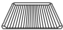 | RACK-WIRE | DG59-00001A | 1 |
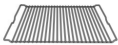 | RACK-WIRE ROAST | DG59-00004A | 1 |
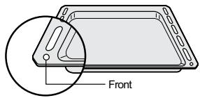 | TRAY-BAKING A | DG63-00012A | 1 |
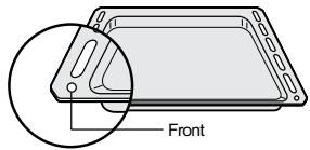 | TRAY-BAKING B | DG63-00011A | 1 |
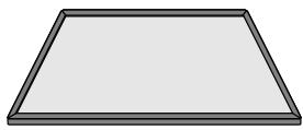 | ASSY-PARTITION | DG97-00015A | 1 |
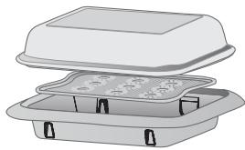 | STEAM-GLASSSTEAM-TRAY SUBSTEAM-TRAY | DG01-00010ADG63-00246ADG63-00242A | 1 |
3. Disassembly and Reassembly
3-1 Tools for Removal and Reassembly
| Tool | |
1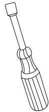 | 1. Tool : Nut Driver2. Type : 7mm3. Remarks : Heater bracket Nut |
2 | 1. Tool : Nut Driver2. Type : 9mm3. Remarks : Convection Fan Nut |
| -AA6H] | 1. Tool : Longnose2. Remarks : Tube Clamp |
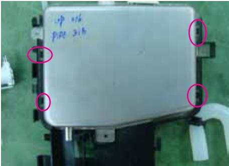
3-2 Replacement of Case upper & Cover back
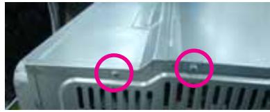
natural_image
Close-up of a metallic industrial component with two pink circular annotations highlighting features (no text or symbols present)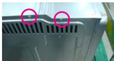
natural_image
Close-up of a computer drive casing with two pink circular annotations highlighting the ventilation grille (no text or symbols present)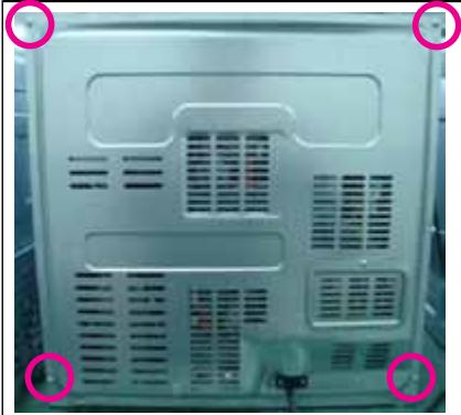
natural_image
Back view of a server rack with ventilation grilles and mounting points circled (no text or symbols visible)* You must remove it before the repair
3. Disassembly and Reassembly
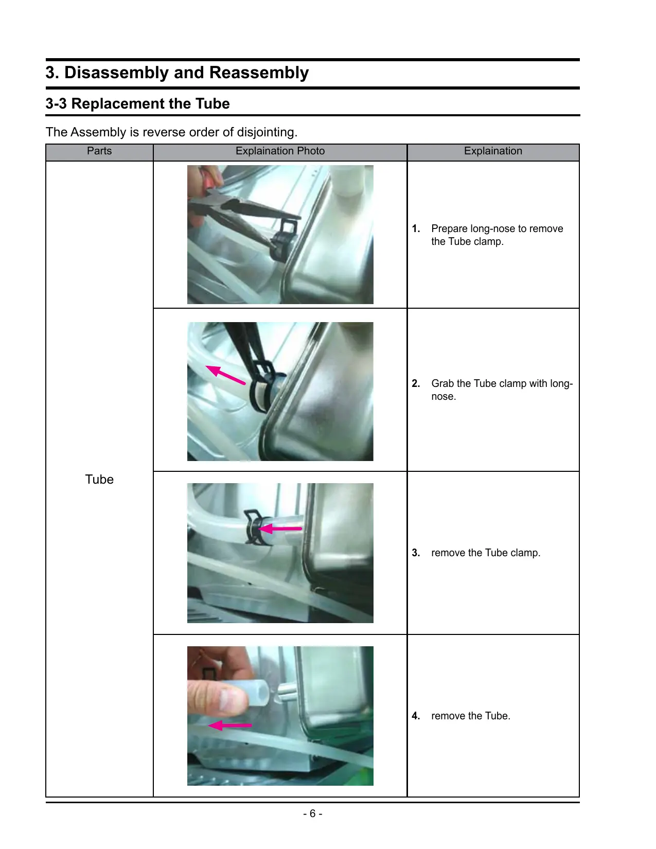
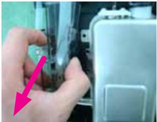
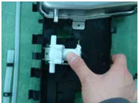
3-3 Replacement the Tube
The Assembly is reverse order of disjointing.
| Parts | Explanation Photo | Explanation |
| Tube | 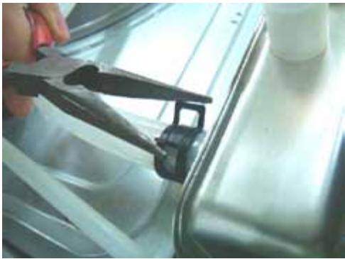 | 1. Prepare long-nose to remove the Tube clamp. |
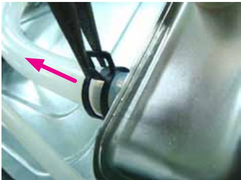 | 2. Grab the Tube clamp with long-nose. | |
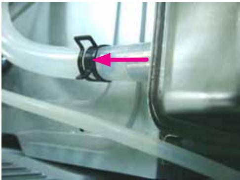 | 3. remove the Tube clamp. | |
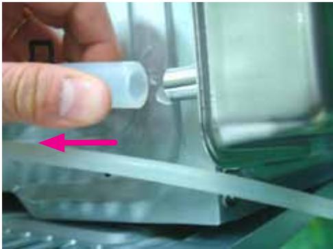 | 4. remove the Tube. |
3. Disassembly and Reassembly
3-4 Replacement of Door Assembly
The Assembly is reverse order of disjointing.
| Parts | Explanation Photo | Explanation |
| Door Assembly | 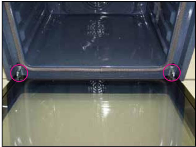 | 1. Turn over the clips of both hinges. |
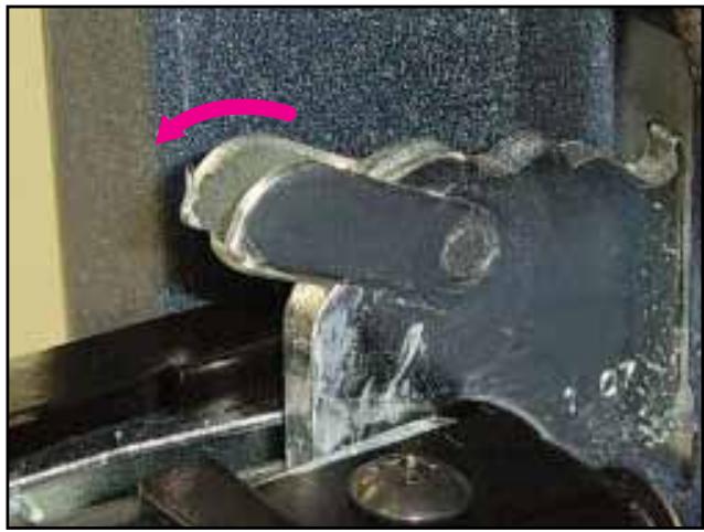 | ||
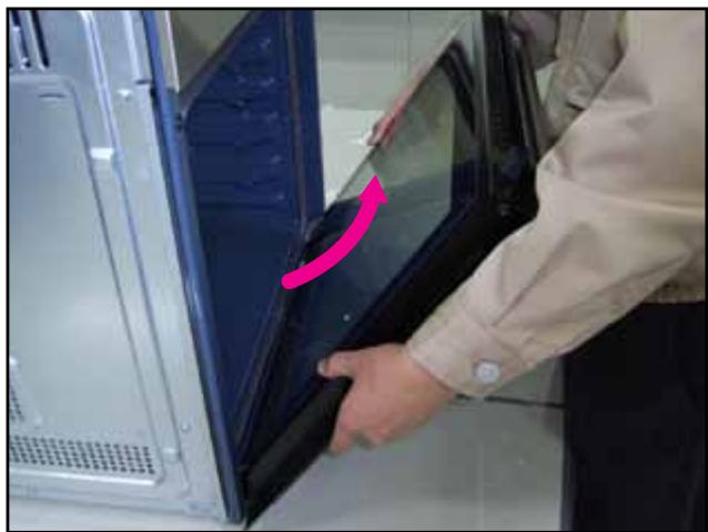 | 2. With both hands, grasp the middle sides of the oven door.3. Rotate the door by approx. 70degree until the hinges can be taken out completely from the hinges holes. |
3-5 Replacement of Door Glass
The Assembly is reverse order of disjointing.
WARNING
Whenever the door is separated from the oven, the clips should always be turned over.
When the door is mounted, if some of the parts (Door glass or other parts) are removed from the door, it can cause injury due to sheet.
ATTENTION
The glass may break if you use force especially on the edges of the front sheet.
| Parts | Explanation Photo | Explanation |
| Door Glass | 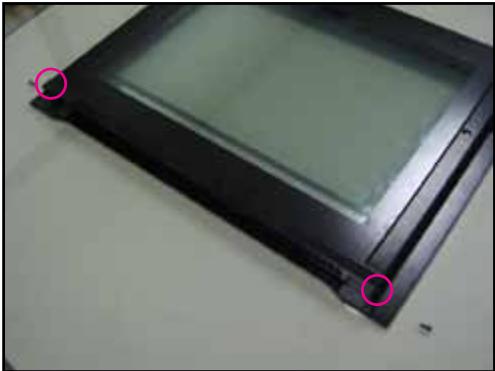 | 1. Remove the two screws of the left and right sides of the door. |
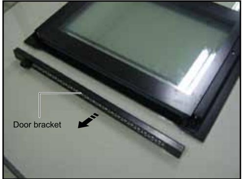 | 2. Take off the door bracket. | |
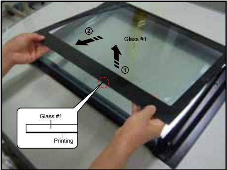 | 3. Detach the inner glass #1 (number 1) from the door.* When assembly the inner glass#1, put printing to direction below. |
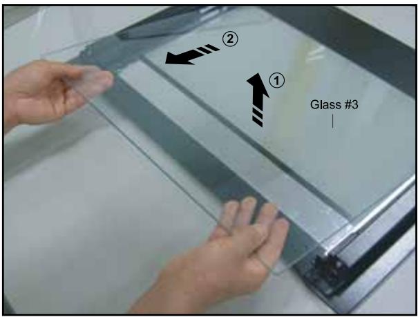
3-5 Replacement of Door Glass (Continued)
The Assembly is reverse order of disjointing.
| Parts | Explanation Photo | Explanation |
| Door Glass | 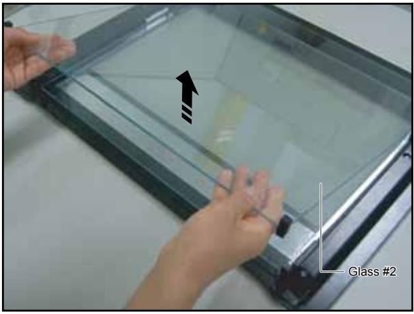 | 4. Detach the inner glass #2 and spring-brackets from the door. |
 | ||
 |
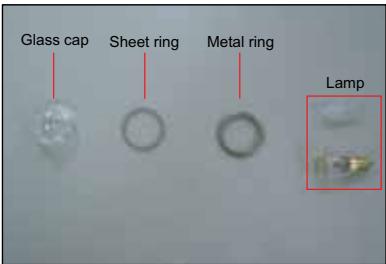
3-6 Replacement of the rear oven Lamp Bulb
The Assembly is reverse order of disjointing.
| Parts | Explanation Photo | Explanation |
| Lamp Bulb | 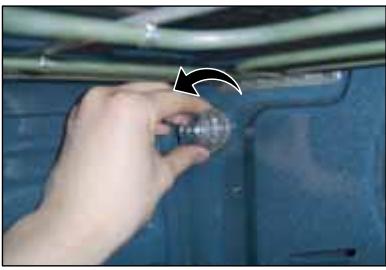 | Take off the cap by turning counterclockwise.Remove the metal ring and the sheet ring and clean the glass cap.If necessary, replace the bulb with a 25 watt, 230 V, 300 °C heat - resistant oven light bulb.Fit the metal and the sheet ring to the glass cap.Replace the glass cap. |
 |
3-7 Replacement of the side Halogen Lamp
The Assembly is reverse order of disjointing.
| Parts | Explanation Photo | Explanation |
| Lamp Bulb | 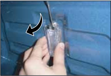 | 1. To remove the glass cover, hold the lower end with one hand, insert a flat sharp implement such as a table knife between the glass and the frame and pop out the cover.2. If necessary, replace the halogen bulb with a 25 ~ 40 watt, 230 V, 300 °C heat - resistant halogen oven light bulb. |
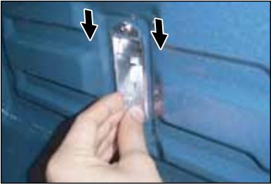 | TipAlways use a cloth when handling a halogen bulb to avoid depositing oils from your fingers on to the surface of the bulb.3. Replace the glass cover. |
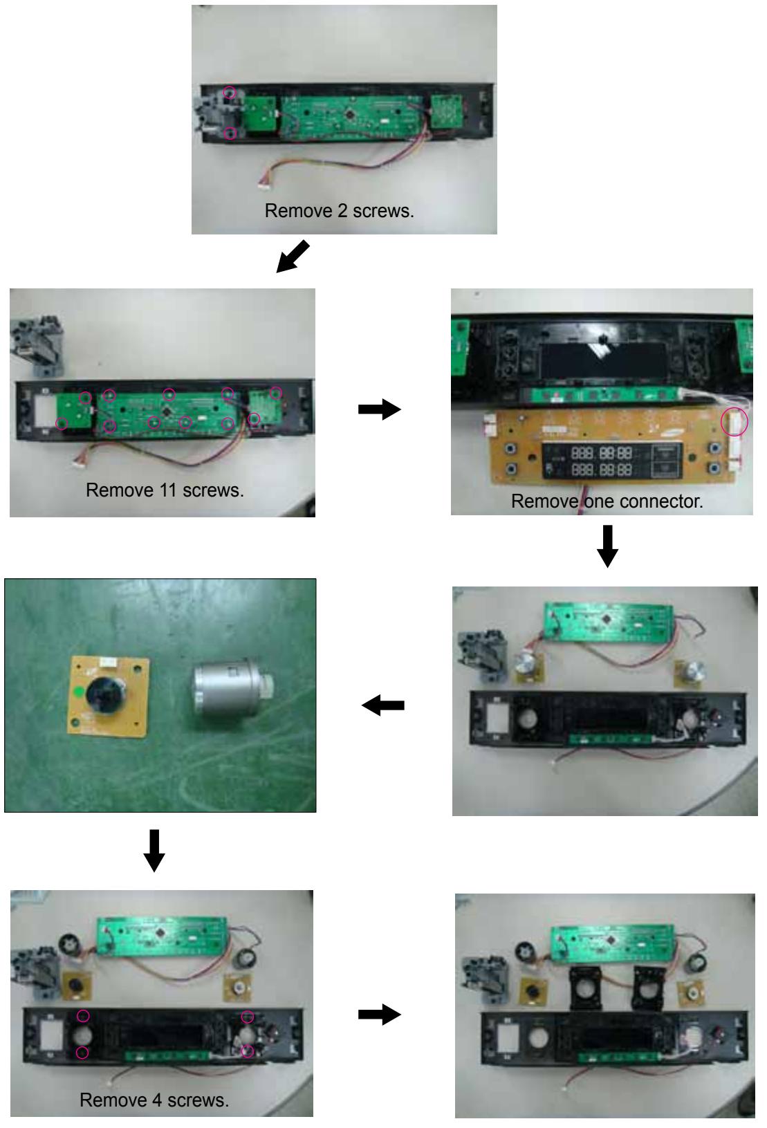
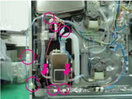
3-8 Replacement of Assy Control Box
The Assembly is reverse order of disjointing.
| Parts | Explanation Photo | |
| Assy Control Box | 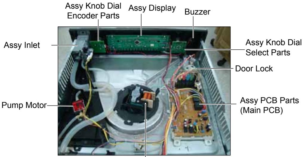 Motor Fan Cooling Motor Fan Cooling | |
| Explanation Photo | Explanation | |
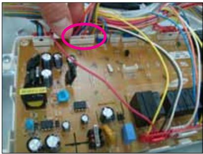 | 1. Remove one connector from the main pcb. | |
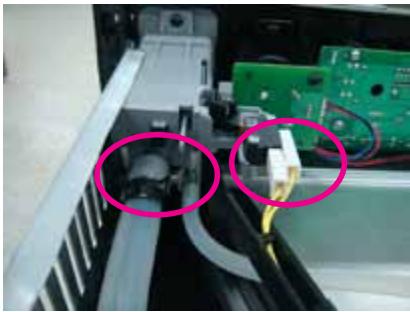 | 2. Remove two Tubes and one connector at assy inlet. | |
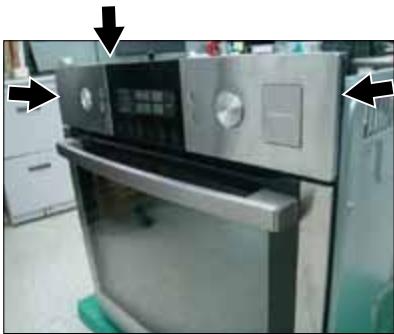 | 3. Remove 3 screws at both sides and top inside of assy control box, lift up assy control box and pull forward to separate. | |
3-8 Replacement of Assy Control Box (Continued)
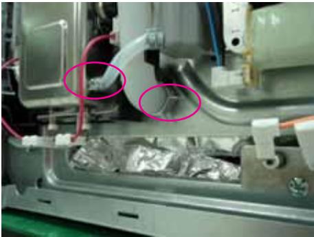
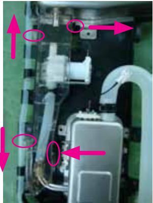
3-9 Replacement of Tube Steam Module
The Assembly is reverse order of disjointing.
| Parts | Explanation Photo | Explanation |
| Tube Steam Module | 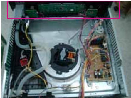 | 1. Remove the control-box. |
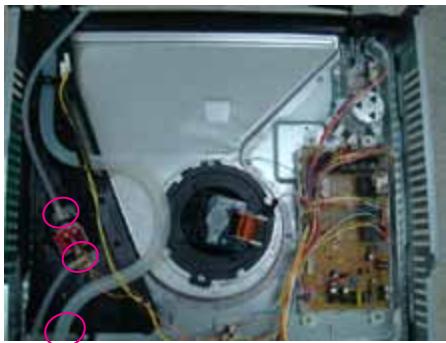 | 2. Remove the 3 tubes. | |
 | 3. Remove the 2 connectors and 4 hook. | |
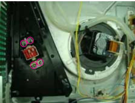 | 4. Remove the 4 screws. |
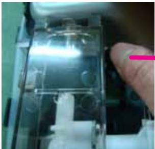
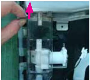
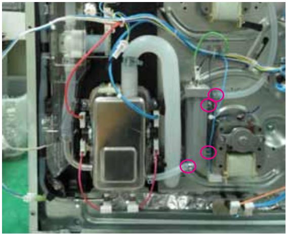
3-9 Replacement of Tube Steam Module (Continued)
The Assembly is reverse order of disjointing.
| Parts | Explanation Photo | Explanation |
| Tube Steam Module | 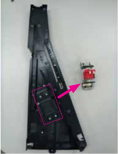 | 5. Remove the Pump Motor. |
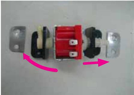 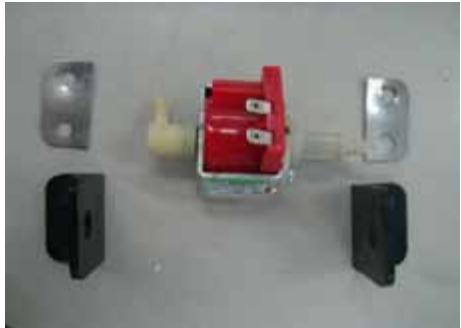 | 6. Remove 2 rubbers. |
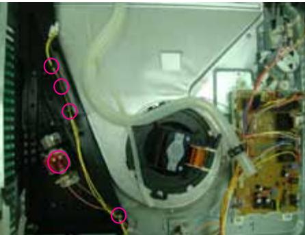
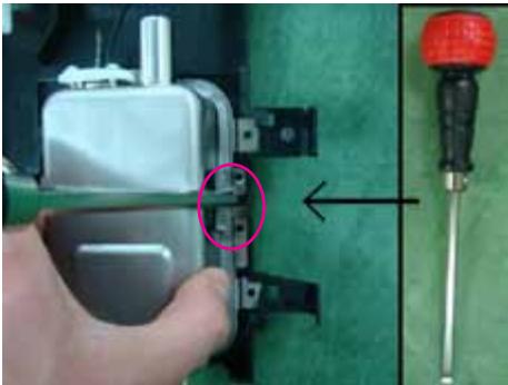
3-10 Replacement of Assy Steam Module
The Assembly is reverse order of disjointing.
| Parts | Explanation Photo | Explanation |
| Assy Steam Module | 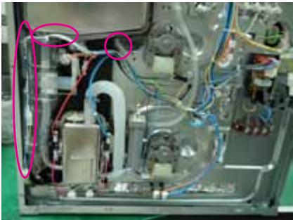 | 1. Seperate the wire-harness from the hook on assy steam module and separate the 1 tube from assy steam generator. |
 | 2. Remove 7 connectors and 2 TCO from the assy steam generator.* Lower Lamp is optional. | |
 | 3. Seperate the 2 tubes. | |
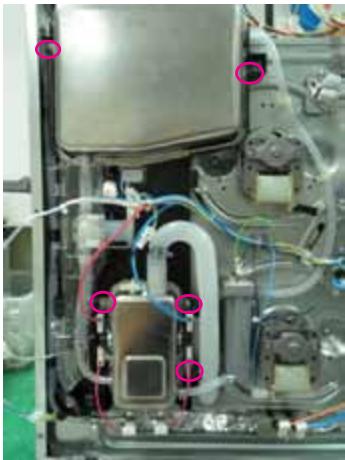 | 4. Remove 5 screws. |
3-10 Replacement of Assy Steam Module (Continued)
The Assembly is reverse order of disjointing.
| Parts | Explanation Photo | Explanation |
| Assy Steam Module | 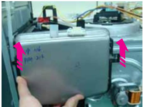 | 5. Lift up assy steam module to seperate from oven. |
    | Separate the cover upper steam.There are totally 4 hook that each has different direction.6. Seperate right and up side hook first.7. Seperate left and up side hook also.8. Seperate last 2 hook. |
3-10 Replacement of Assy Steam Module (Continued)
The Assembly is reverse order of disjointing.
| Parts | Explanation Photo | Explanation |
| Assy Steam Module | 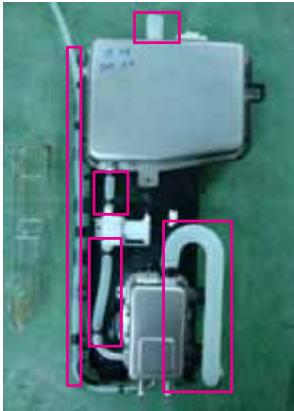 | 9. Remove 5 tubes. |
 | 10. Seperate the right side hook by using a flat head screwdriver. And then remove the assy steam generator. | |
 | 11. Seperate the right side hook by using a flat head screwdriver. And then remove the water valve. | |
 | 12. Seperate the 4 hook by using a flat head screwdriver. And then remove the assy water tank. |
3-11 Assembly for Main Assy Steam module part
| Parts | Explanation Photo | Explanation |
| Assy Water tank | 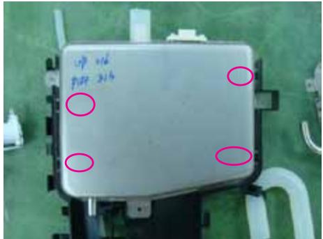 | 1. Press the 4 point of assy water tank and check the right assembly with hook. |
| Water valve | 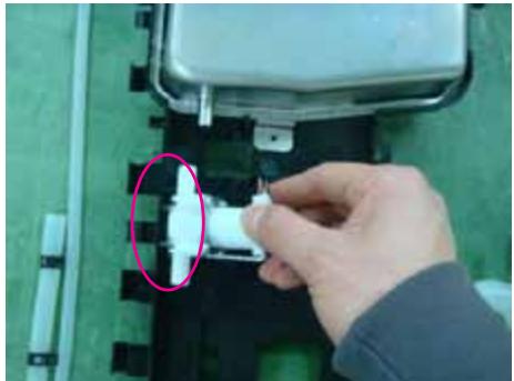 | 1. Insert left side of water valve into hook. |
 | 2. Press the right side of water valve. | |
| Assy Steam generator | 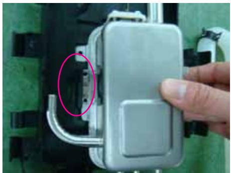 | 1. Insert left side of assy steam generator into hook. |
| Assy Steam generator | 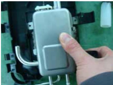 | 2. Press the right side of assy steam generator. |
| Connectors and Assy steam module | 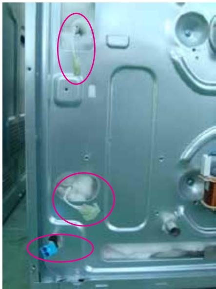 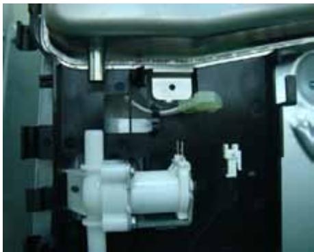 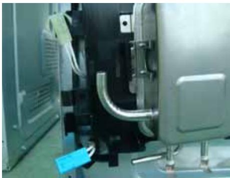 | 1. Check the right position between assy steam module hole and connector. |
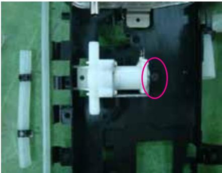
3-12 Replacement of Assy generator sub
| Parts | Explanation Photo | Explanation |
| Assy generator sub | 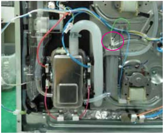 | 1. Remove 2 connectors.2. Remove the 2 tubes and 2 screws. |
 |
3-13 Replacement of Motor Fan Cooling
The Assembly is reverse order of disjointing.
| Parts | Explanation Photo | Explanation |
| Fan Cooling | 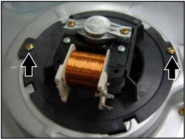 | 1. Remove two screws and turn toward the clockwise to separate. |
3-14 Replacement of Duct Cover, Bracket & Spring Duct & Ceramic Filter
| Parts | Explanation Photo | Explanation |
| Fan Cooling | 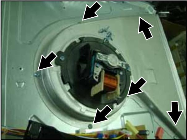 | 1. Remove 6 screws from ass'y cover cooling motor. |
3-15 Replacement of Motor Convection
The Assembly is reverse order of disjointing.
| Parts | Explanation Photo | Explanation |
| Motor Convection | 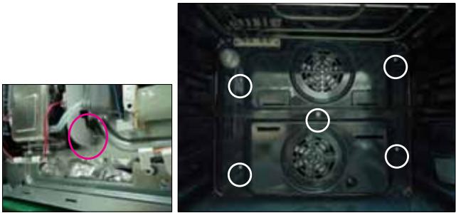 | 1. Seperate the 1 tube from the adiabatic rear.* Be sure to connect tube again when assembly.2. Remove 5 screws at the back inside cavity to separate the cover casing. |
 | 3. Turn flange nut to the left to release and separate spacer fan convection and fan convection. | |
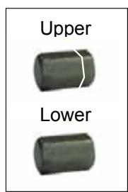
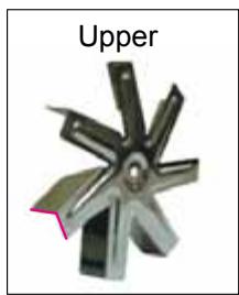
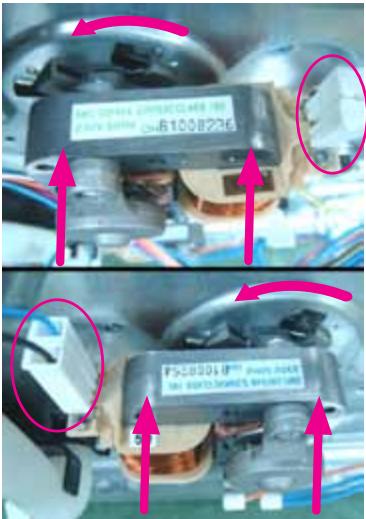 | 4. Remove two connector from convection motor5. Remove turn toward the counter-clockwise to separate.ReferenceConvection fan is turn in the opposite direction each other for improvement cook performance. Upper fan is turn in counter-clockwise direction, Lower fan is fan turn in clockwise direction therefor convection fan direction and netflange are opposited each other.Convection fan is indicated (U),(L) and netflange is different the head shape. |
text_image
Upper LowerNut-Hexagon cap
natural_image
Metal mechanical component with six blades, labeled 'Upper' (no other text or symbols)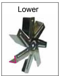
natural_image
Metal mechanical component with six blades and a label 'Lower' (no other text or symbols)Fan-Convection
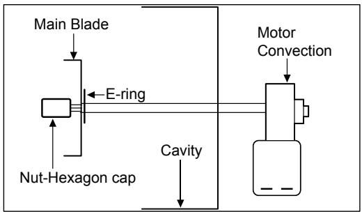
flowchart
graph TD
    A["Main Blade"] --> B["Nut-Hexagon cap"]
    B --> C["E-ring"]
    C --> D["Cavity"]
    D --> E["Motor Convection"]
    E --> F["End"]
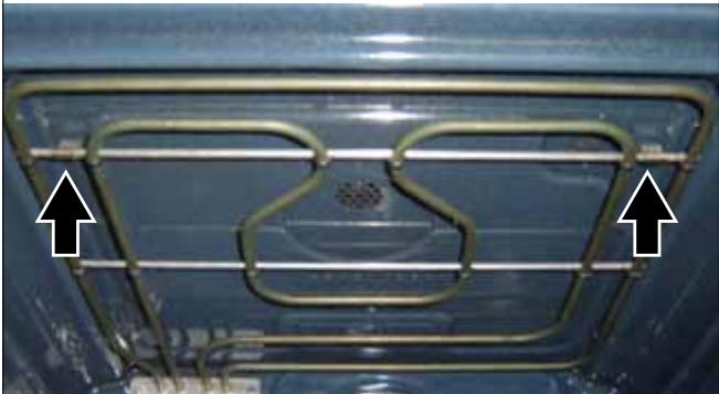
3-16 Replacement of Heater Convection twin
The Assembly is reverse order of disjointing.
| Parts | Explanation Photo | Explanation |
| Heater Convection Twin | 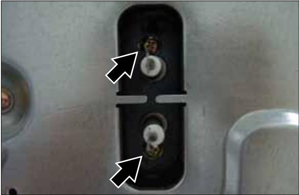 | 1. Remove the two connectors.2. Remove two screws securing heater convection twin at the rear. |
 | 3. Pull the securing bracket at the left forward, and pull it toward the left to separate heater convection twin. |
3-17 Replacement of Assy Partition S/W
| Parts | Explanation Photo | Explanation | |
| Partition S/W | 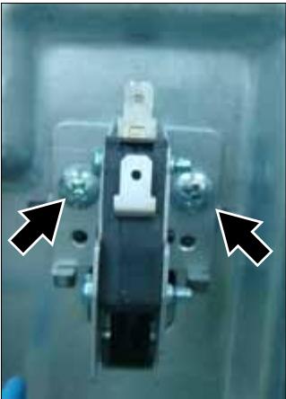 | 1. Remove a connector.2. Remove two screws. | |
3-18 Replacement of Thermostat
The Assembly is reverse order of disjointing.
| Parts | Explanation Photo | Explanation |
| Thermostat | 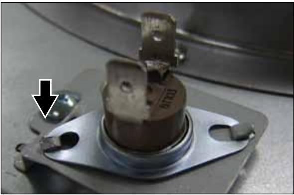 | 1. Unfold one point. |
3-19 Replacement of Terminal Block
| Parts | Explanation Photo | Explanation |
| Terminal Block | 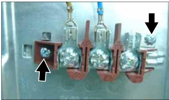 | 1. Remove two wires from terminal block..2. Remove three screws. |
3-20 Replacement of Sensor Thermistor
| Parts | Explanation Photo | Explanation |
| Sensor Thermistor | 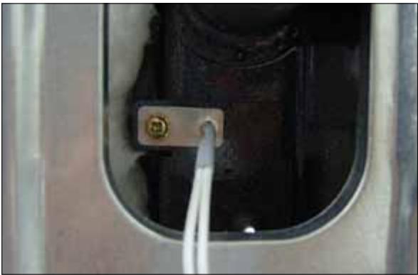 | 1. Remove one screws. |
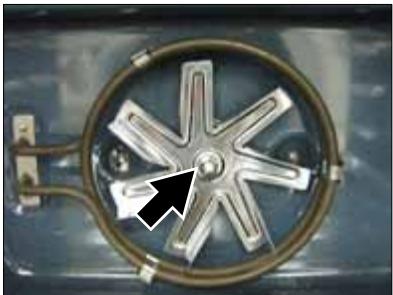
3-21 Replacement of Heater Grill
The Assembly is reverse order of disjointing.
| Parts | Explanation Photo | Explanation |
| Heater Grill |  | 1. Remove the four connectors.2. Remove each nut frange at right and left sides. |
 | 3. Turn the upper nut circular inside the cavity to the counterclockwise to release, pull heater girll forward to separate. |
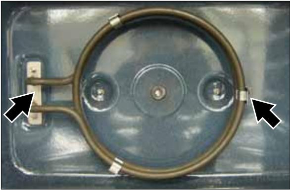
3-22 Replacement of Heater Bottom
| Parts | Explanation Photo | Explanation |
| Heater Bottom | 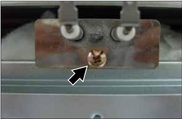 | 1. Remove the two connectors.2. Remove one screw and pull forward to separate it. |
3-23 Replacement of Assy PCB Parts (Main PCB)
The Assembly is reverse order of disjointing.
| Parts | Explanation Photo | Explanation |
| Assy PCB Parts (Main PCB) | 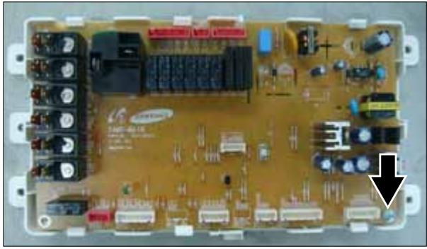 | 1. Remove a screw. |
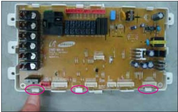 | 2. Seperate 3 hook. |
3-24 Replacement of Assy-Door Lock
| Parts | Explanation Photo | Explanation |
| Assy-Door Lock | 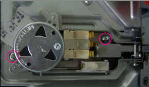 | 1. Remove two screws. |
4. Troubleshooting
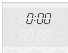
4-1 Failure Codes
There are a kind of error code and two kinds of warning codes. Possible error codes during use can be checked before service. Press [Stand by Mode + Current time 0:00] and [Function + Time] at the same time and hold them for 5 seconds, error codes are displayed. Press [Function] button, the latest 5 error codes can be
text_image
0:00 88:88
natural_image
Hand cursor clicking a black square button (no text or symbols)
natural_image
Hand cursor clicking a black square button with a clock icon (no text or symbols)checked. But, if the oven turns off, the stored error codes are deleted. Press [Function + Time] button to return to 'normal display mode'.
4-1-1 Temp Sensor Error
| Error Code | Gerneral Function | Solution | Page |
 | Cavity upper sensor open | Sensor Open ErrorIt occurs due to a defective sensor, misplaced wires, a defective PCB. | 29 Page |
 | Cavity lower sensor open | ||
 | Cooling motor sensor open | ||
 | Steam generator sensor open | ||
 | Cavity upper sensor short | Sensor Short ErrorIt occurs due to a defective sensor, misplaced wires, a defective PCB. It may occur when the ambient temperature falls under -5°C. | 30 Page |
 | Cavity lower sensor short | ||
 | Cooling motor sensor short | ||
 | Steam generator sensor short |
4-1-2 Safety Error
| Error Code | Gerneral Function | Solution | Page | |
 | Overtime | This error occurs when the oven works during CUT-OFF TIME in the same mode and at the same temperature without any operation of an user.This error is to prevent a risk of fire and hazards in case an user forgets to turn off the oven after use or the oven automatically starts in an unusual way.The oven can be used after off. | 32 Page | |
| Temp | Time | |||
| ~ 100°C | 16 hours | |||
| 105°C ~ 240°C | 8 hours | |||
| 245°C ~ | 4 hours | |||
 | Touch Button Short | This error occurs when a button is pressed and held for over 10 seconds.It may occur when water soaks through the inside of the control panel or dust particles are stuck to TOUCH PAD. In this case, remove DISPLAY PCB,clean TOUCH PAD PCB or replace it. | 31 Page | |
| Error Code | Gerneral Function | Solution | Page | |
| Divider Missing | This error occurs when the divider sensing switch senses that the divider is used at the inappropriate mode. | 33 Page | ||
| Preheating Time Out | This error occurs when the set preheating time, 30 minutes, is over.It may occur due to a heater's open, defects of relay contact point and wiring defects. | 35 Page | ||
| Excess of cooking compartment's temperature | - This error occurs when the temperature of cooking compartment maintains over 320°C for more than 5 minutes.- This error occurs when a fire occurs inside cooking compartment or the temperature cannot be controlled because of sensor's failure. | 38 Page | ||
| Excess of cooking compartment's temperature | - This error occurs immediately after the temperature of cooking compartment reaches 350°C.- This error occurs when a fire occurs inside cooking compartment or the temperature cannot be controlled because of sensor's failure. | 38 Page | ||
| Cooling motor lock sensed | - This error occurs when the temperature sensor on the Main PCB senses abnormal temperature.- It occurs 30 ~ 60 minutes after the cooling motor does not operate.- It may occur when the cooling motor stops running by power off during operation of the oven, then it runs again. | 34 Page | ||
| Excess of steam generator temperature | - This error occurs when the temperature sensor in the steam generator senses abnormal temperature. | 36 Page | ||
| Water valve open sensed | - This error occurs when generator sensor can not sense the water even though water valve is opened for 30 sec. | 28 Page | ||
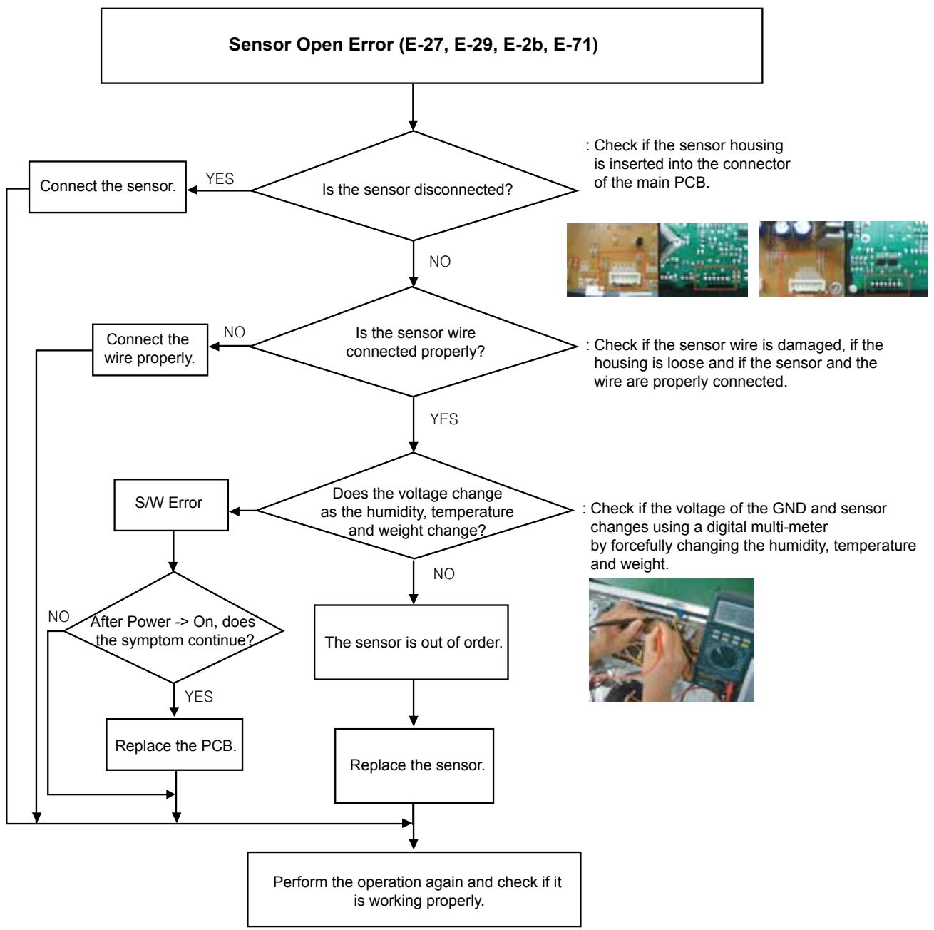
flowchart
graph TD
    A["Sensor Open Error (E-27, E-29, E-2b, E-71)"] --> B{Is the sensor disconnected?}
    B -->|YES| C["Connect the sensor."]
    B -->|NO| D{Is the sensor wire connected properly?}
    D -->|YES| E{Does the voltage change as the humidity, temperature and weight change?}
    D -->|NO| F["Connect the wire properly."]
    E -->|YES| G["S/W Error"]
    E -->|NO| H["After Power --> On, does the symptom continue?"]
    G --> I{Replace the PCB.}
    H --> I
    I --> J["Perform the operation again and check if it is working properly."]
    J --> K["Replace the sensor."]
    K --> L["The sensor is out of order."]
    L --> M["Check if the sensor wire is damaged, if the housing is loose and if the sensor and the wire are properly connected."]
    M --> N["Check if the sensor wire is inserted into the connector of the main PCB."]
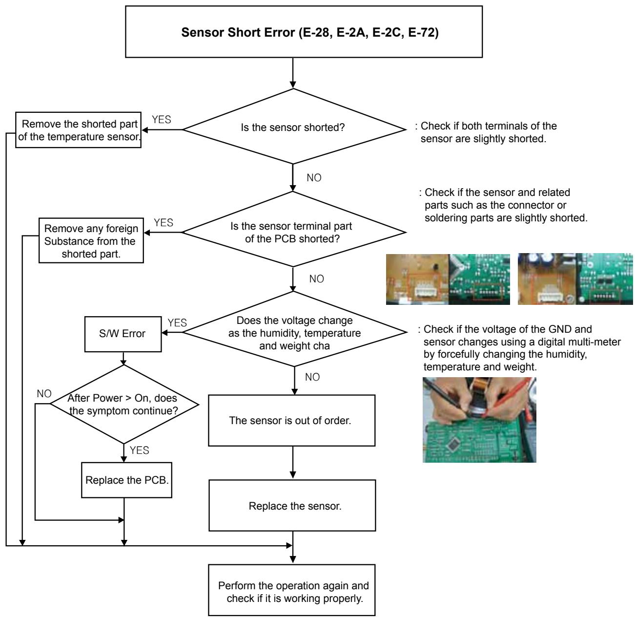
flowchart
graph TD
    A["Sensor Short Error (E-28, E-2A, E-2C, E-72)"] --> B{Is the sensor shorted?}
    B -->|YES| C["Remove the shorted part of the temperature sensor"]
    B -->|NO| D{Is the sensor terminal part of the PCB shorted?}
    D -->|YES| E["Remove any foreign Substance from the shorted part"]
    D -->|NO| F{Does the voltage change as the humidity, temperature and weight cha}
    F -->|YES| G["S/W Error"]
    F -->|NO| H["The sensor is out of order."]
    H --> I["Replace the sensor."]
    I --> J["Perform the operation again and check if it is working properly."]
    G --> K{After Power > On, does the symptom continue?}
    K -->|NO| L["Replace the PCB."]
    K -->|YES| M["Check if the sensor and related parts such as the connector or soldering parts are slightly shorted."]
    L --> N["Perform the operation again and check if it is working properly."]
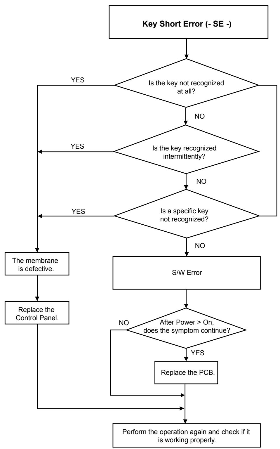
flowchart
graph TD
    A["Key Short Error (- SE -)"] --> B{Is the key not recognized at all?}
    B -->|YES| C["The membrane is defective."]
    B -->|NO| D{Is the key recognized intermittently?}
    D -->|YES| C
    D -->|NO| E{Is a specific key not recognized?}
    E -->|YES| C
    E -->|NO| F["S/W Error"]
    F --> G{After Power > On, does the symptom continue?}
    G -->|NO| H["Replace the Control Panel."]
    G -->|YES| I["Replace the PCB."]
    I --> J["Perform the operation again and check if it is working properly."]
    C --> K["The membrane is defective."]
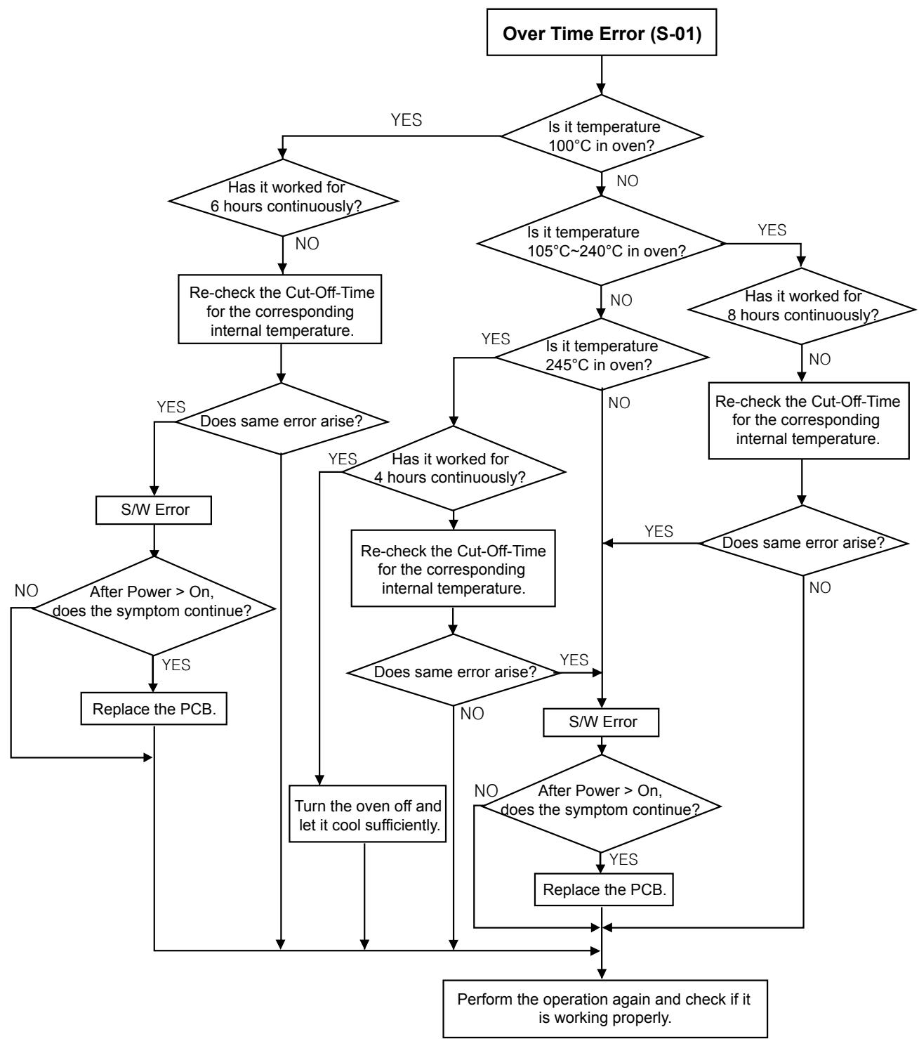
flowchart
graph TD
    A["Over Time Error (S-01)"] --> B{Is it temperature 100°C in oven?}
    B -->|YES| C{Has it worked for 6 hours continuously?}
    B -->|NO| D{Is it temperature 105°C~240°C in oven?}
    D -->|YES| E{Has it worked for 8 hours continuously?}
    D -->|NO| F{Is it temperature 245°C in oven?}
    F -->|YES| G{Does same error arise?}
    F -->|NO| H["Re-check the Cut-Off-Time for the corresponding internal temperature."]
    G -->|YES| I["S/W Error"]
    G -->|NO| J{Does same error arise?}
    J -->|YES| K["Re-check the Cut-Off-Time for the corresponding internal temperature."]
    J -->|NO| L{Does same error arise?}
    K --> M{Does same error arise?}
    L --> M
    M -->|YES| N["S/W Error"]
    M -->|NO| O["Turn the oven off and let it cool sufficiently."]
    N --> P["Perform the operation again and check if it is working properly."]
    O --> P
    P --> Q["Replace the PCB."]
    Q --> R{After Power > On, does the symptom continue?}
    R -->|YES| S["Re-check the Cut-Off-Time for the corresponding internal temperature."]
    S --> T{Does same error arise?}
    T -->|YES| U["S/W Error"]
    T -->|NO| V{Does same error arise?}
    V -->|YES| W["Re-check the Cut-Off-Time for the corresponding internal temperature."]
    W --> X{Does same error arise?}
    X -->|YES| Y["S/W Error"]
    X -->|NO| Z["Replace the PCB."]
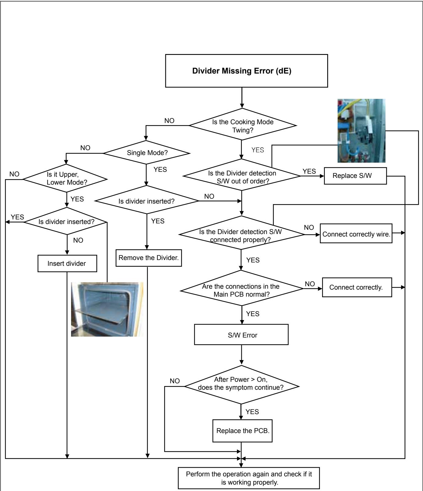
flowchart
graph TD
    A["Divider Missing Error (dE)"] --> B{Is the Cooking Mode Twing?}
    B -->|NO| C{Single Mode?}
    B -->|YES| D{Is the Divider detection S/W out of order?}
    C -->|NO| E{Is it Upper, Lower Mode?}
    C -->|YES| F{Is divider inserted?}
    D -->|YES| G{Is the Divider detection S/W connected properly?}
    D -->|NO| H["Remove the Divider."]
    E -->|YES| I{Are the connections in the Main PCB normal?}
    E -->|NO| J["Connect correctly wire."]
    F -->|YES| K["Remove the Divider."]
    F -->|NO| L["S/W Error"]
    G -->|YES| M{Are the connections in the Main PCB normal?}
    G -->|NO| N["Connect correctly."]
    H --> O["Perform the operation again and check if it is working properly."]
    I --> P{After Power > On, does the symptom continue?}
    P -->|NO| Q["Remove the Divider."]
    P -->|YES| R["Replace the PCB."]
    Q --> S["Perform the operation again and check if it is working properly."]
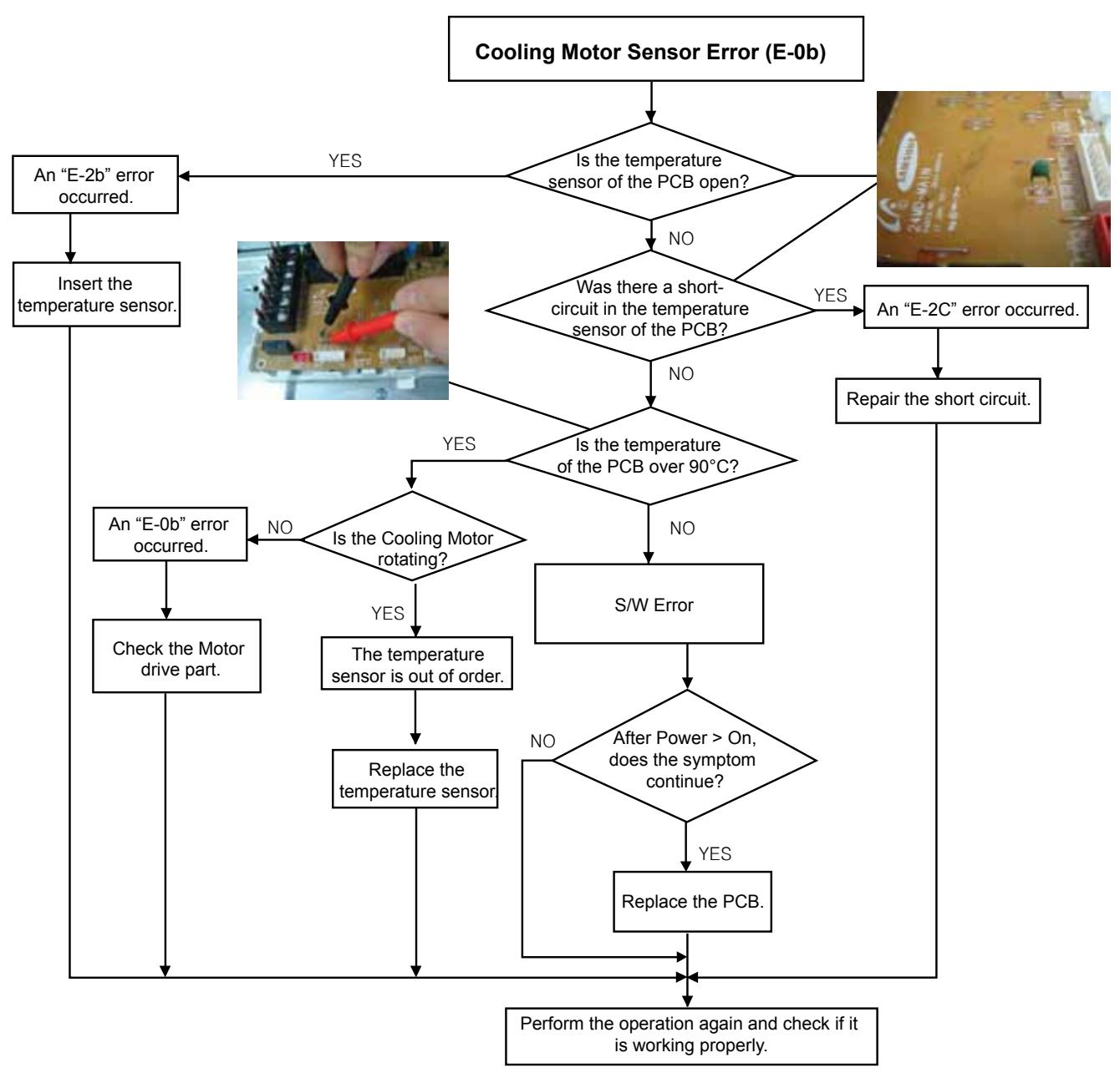
flowchart
graph TD
    A["Cooling Motor Sensor Error (E-0b)"] --> B{Is the temperature sensor of the PCB open?}
    B -->|YES| C["An "E-2b" error occurred"]
    B -->|NO| D{Was there a short-circuit in the temperature sensor of the PCB?}
    D -->|YES| E["An "E-2C" error occurred"]
    D -->|NO| F{Is the temperature of the PCB over 90°C?}
    F -->|YES| G{Is the Cooling Motor rotating?}
    F -->|NO| H["S/W Error"]
    G -->|YES| I["Check the Motor drive part."]
    G -->|NO| J["Perform the operation again and check if it is working properly."]
    H --> K["Replace the temperature sensor"]
    I --> L["Perform the operation again and check if it is working properly."]
    J --> M["Perform the operation again and check if it is working properly."]
    N["Insert the temperature sensor."] --> O["An "E-0b" error occurred."]
    O --> P["Check the motor drive part."]
    P --> Q["Perform the operation again and check if it is working properly."]
    R["Repair the short circuit."] --> F
    S["The temperature sensor is out of order."] --> T["Replace the temperature sensor"]
    T --> U["Perform the operation again and check if it is working properly."]
    V["After Power > On, does the symptom continue?"] --> W{Yes}
    W --> X["Replace the PCB."]
    X --> Y["Perform the operation again and check if it is working properly."]
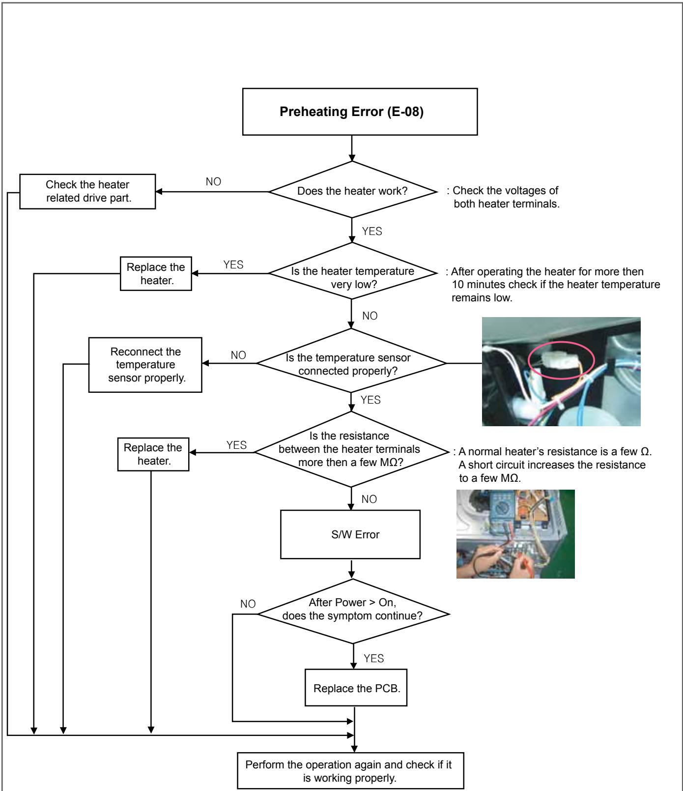
flowchart
graph TD
    A["Preheating Error (E-08)"] --> B{Does the heater work?}
    B -->|NO| C["Check the heater related drive part."]
    B -->|YES| D{Is the heater temperature very low?}
    D -->|YES| E["Replace the heater."]
    D -->|NO| F{Is the temperature sensor connected properly?}
    F -->|NO| G["Reconnect the temperature sensor properly."]
    F -->|YES| H{Is the resistance between the heater terminals more then a few MΩ?}
    H -->|YES| I["Replace the heater."]
    H -->|NO| J["S/W Error"]
    J --> K{After Power > On, does the symptom continue?}
    K -->|NO| L["Perform the operation again and check if it is working properly."]
    K -->|YES| M["Replace the PCB."]
    M --> K
    style A fill:#f9f,stroke:#333
    style K fill:#ccf,stroke:#333
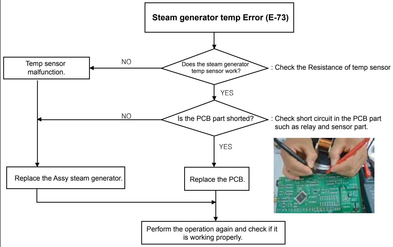
flowchart
graph TD
    A["Steam generator temp Error (E-73)"] --> B{Does the steam generator temp sensor work?}
    B -->|NO| C["Temp sensor malfunction."]
    B -->|YES| D{Is the PCB part shorted?}
    D -->|NO| E["Replace the Assy steam generator."]
    D -->|YES| F["Replace the PCB."]
    E --> G["Perform the operation again and check if it is working properly."]
    F --> G
    style A fill:#f9f,stroke:#333
    style G fill:#ccf,stroke:#333
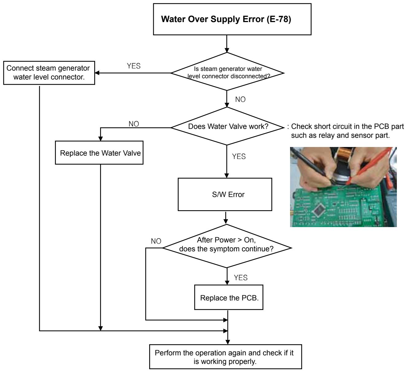
flowchart
graph TD
    A["Water Over Supply Error (E-78)"] --> B{Is steam generator water level connector disconnected?}
    B -->|YES| C["Connect steam generator water level connector."]
    B -->|NO| D{Does Water Valve work?}
    D -->|YES| E["S/W Error"]
    D -->|NO| F["Replace the Water Valve"]
    F --> G{After Power > On, does the symptom continue?}
    G -->|YES| H["Replace the PCB."]
    G -->|NO| I["Perform the operation again and check if it is working properly."]
    H --> I
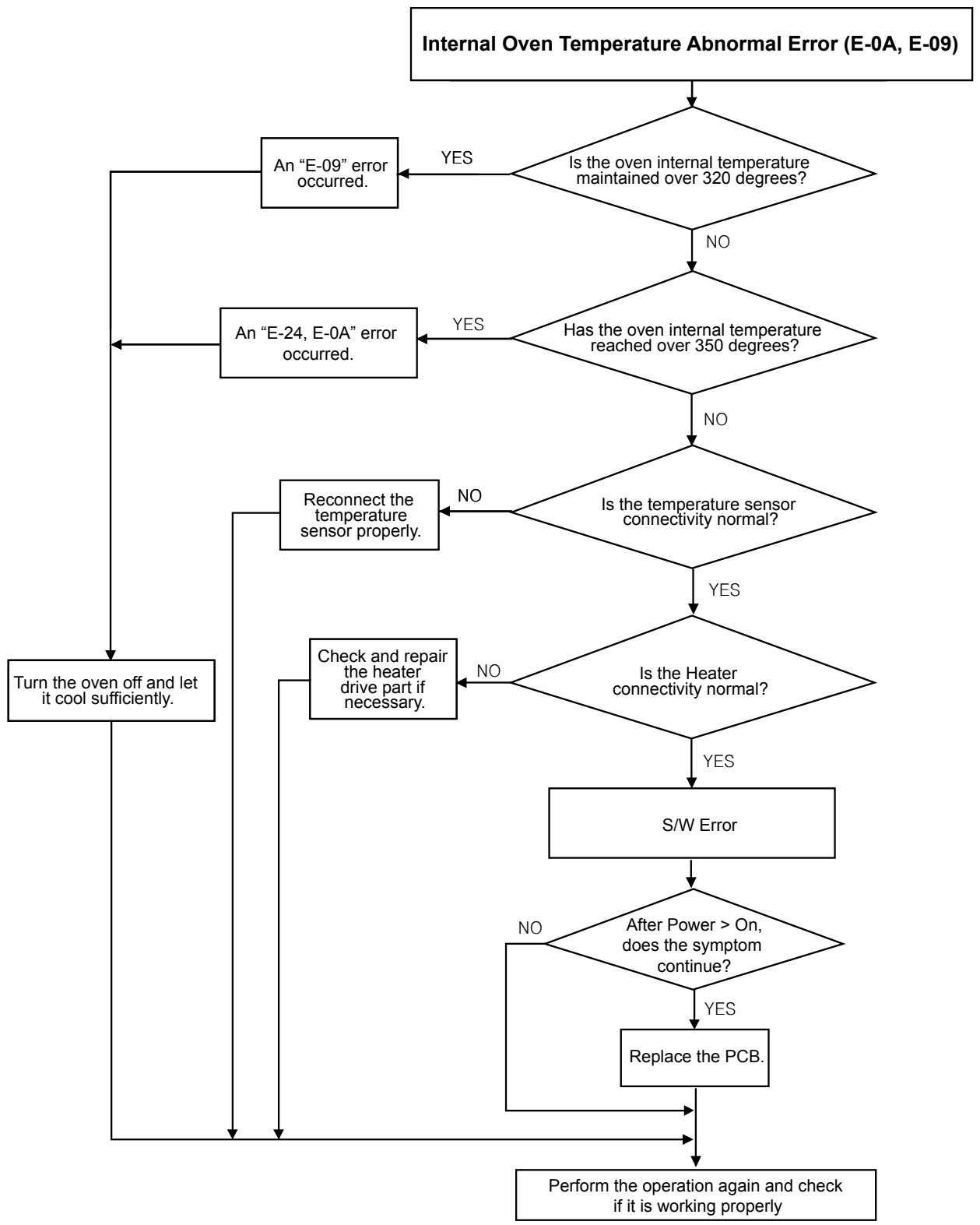
flowchart
graph TD
    A["Internal Oven Temperature Abnormal Error (E-0A, E-09)"] --> B{Is the oven internal temperature maintained over 320 degrees?}
    B -->|YES| C["An "E-09" error occurred."]
    B -->|NO| D{Has the oven internal temperature reached over 350 degrees?}
    D -->|YES| E["An "E-24, E-0A" error occurred."]
    D -->|NO| F{Is the temperature sensor connectivity normal?}
    F -->|YES| G{Is the Heater connectivity normal?}
    F -->|NO| H["Reconnect the temperature sensor properly."]
    G -->|YES| I["Check and repair the heater drive part if necessary."]
    G -->|NO| J["Turn the oven off and let it cool sufficiently."]
    H --> K["S/W Error"]
    I --> K
    J --> K
    K --> L{After Power > On, does the symptom continue?}
    L -->|NO| K
    L -->|YES| M["Replace the PCB."]
    M --> N["Perform the operation again and check if it is working properly"]
    L --> O["End"]
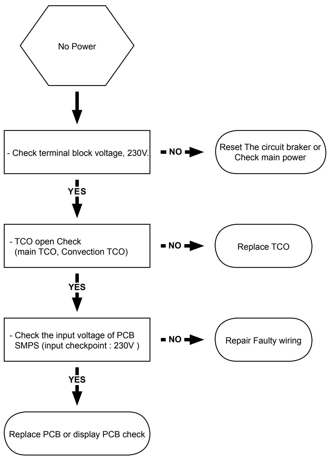
flowchart
graph TD
    A["No Power"] --> B["- Check terminal block voltage, 230V."]
    B -->|YES| C["- TCO open Check (main TCO, Convection TCO)"]
    C -->|YES| D["- Check the input voltage of PCB SMPS (input checkpoint : 230V.)"]
    D -->|YES| E["Replace PCB or display PCB check"]
    B -->|NO| F["Reset The circuit broker or Check main power"]
    C -->|NO| G["Replace TCO"]
    D -->|NO| H["Repair Faulty wiring"]
4-1-14 TCO Open
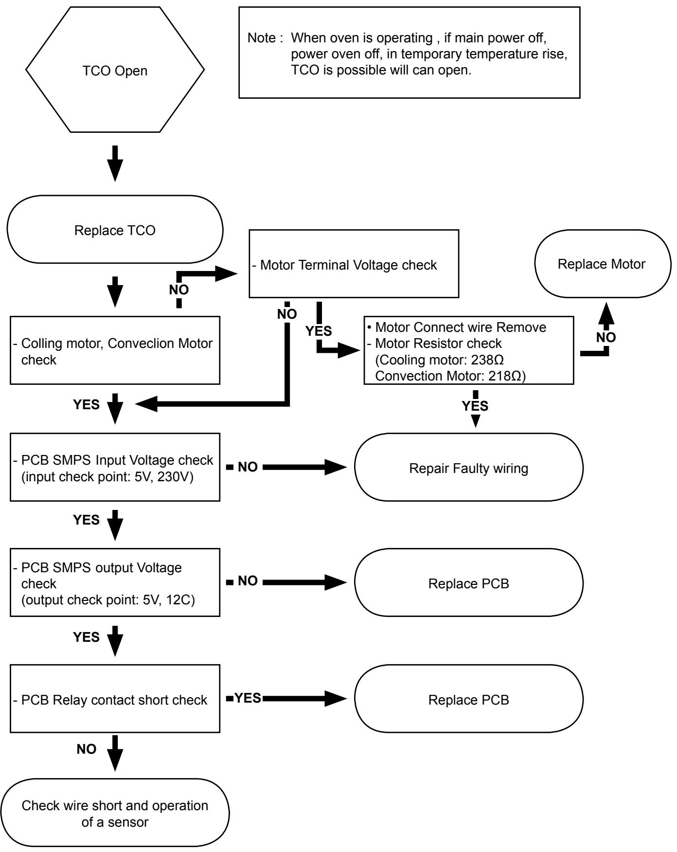
flowchart
graph TD
    A["TCO Open"] --> B["Replace TCO"]
    B --> C["- Colling motor, Convection Motor check"]
    C --> D{Motor Terminal Voltage check}
    D -->|NO| E["Repair Faulty wiring"]
    D -->|YES| F["• Motor Connect wire Remove\n- Motor Resistor check\n(Cooling motor: 238Ω\nConvection Motor: 218Ω)"]
    F --> G{PCB SMPS Input Voltage check\n(input check point: 5V, 230V)}
    G -->|NO| H["Repair Faulty wiring"]
    G -->|YES| I["PCB SMPS output Voltage check\n(output check point: 5V, 12C)"]
    I --> J{PCB Relay contact short check}
    J -->|NO| K["Repair Faulty wiring"]
    J -->|YES| L["PCB SMPS output Voltage check\n(output check point: 5V, 12C)"]
    L --> M{PCB Relay contact short check}
    M -->|NO| N["Check wire short and operation of a sensor"]
    M -->|YES| O["PCB SMPS output Voltage check\n(output check point: 5V, 12C)"]
    O --> P["Repair Faulty wiring"]
    O --> Q["PCB SMPS output Voltage check\n(output check point: 5V, 12C)"]
    P --> R["Repair Faulty wiring"]
    P --> S["PCB SMPS output Voltage check\n(output check point: 5V, 12C)"]
    R --> T["Repair Faulty wiring"]
    R --> U["PCB SMPS output Voltage check\n(output check point: 5V, 12C)"]
    T --> V["Repair Faulty wiring"]
    T --> W["PCB SMPS output Voltage check\n(output check point: 5V, 12C)"]
    U --> X["Repair Faulty wiring"]
    U --> Y["PCB SMPS output Voltage check\n(output check point: 5V, 12C)"]
    V --> Z["Repair Faulty wiring"]
    V --> AA["PCB SMPS output Voltage check\n(output check point: 5V, 12C)"]
    W --> AB["Repair Faulty wiring"]
    W --> AC["PCB SMPS output Voltage check\n(output check point: 5V, 12C)"]
    X --> AD["Repair Faulty wiring"]
    X --> AE["PCB SMPS output Voltage check\n(output check point: 5V, 12C)"]
    Y --> AF["Repair Faulty wiring"]
    Y --> AG["PCB SMPS output Voltage check\n(output check point: 5V, 12C)"]
    Z --> AH["Repair Faulty wiring"]
    Z --> AI["PCB SMPS output Voltage check\n(output check point: 5V, 12C)"]
    AA --> AJ["Repair Faulty wiring"]
    AA --> AK["PCB SMPS output Voltage check\n(output check point: 5V, 12C)"]
    AB --> AL["Repair Faulty wiring"]
    AB --> AM["PCB SMPS output Voltage check\n(output check point: 5V, 12C)"]
    AC --> AN["Repair Faulty wiring"]
    AC --> AO["PCB SMPS output Voltage check\n(output check point: 5V, 12C)"]
    AD --> AP["Repair Faulty wiring"]
    AD --> AQ["PCB SMPS output Voltage check\n(output check point: 5V, 12C)"]
    AE --> AR["Repair Faulty wiring"]
    AE --> AS["PCB SMPS output Voltage check\n(output check point: 5V, 12C)"]
4-1-15 PCB Failure
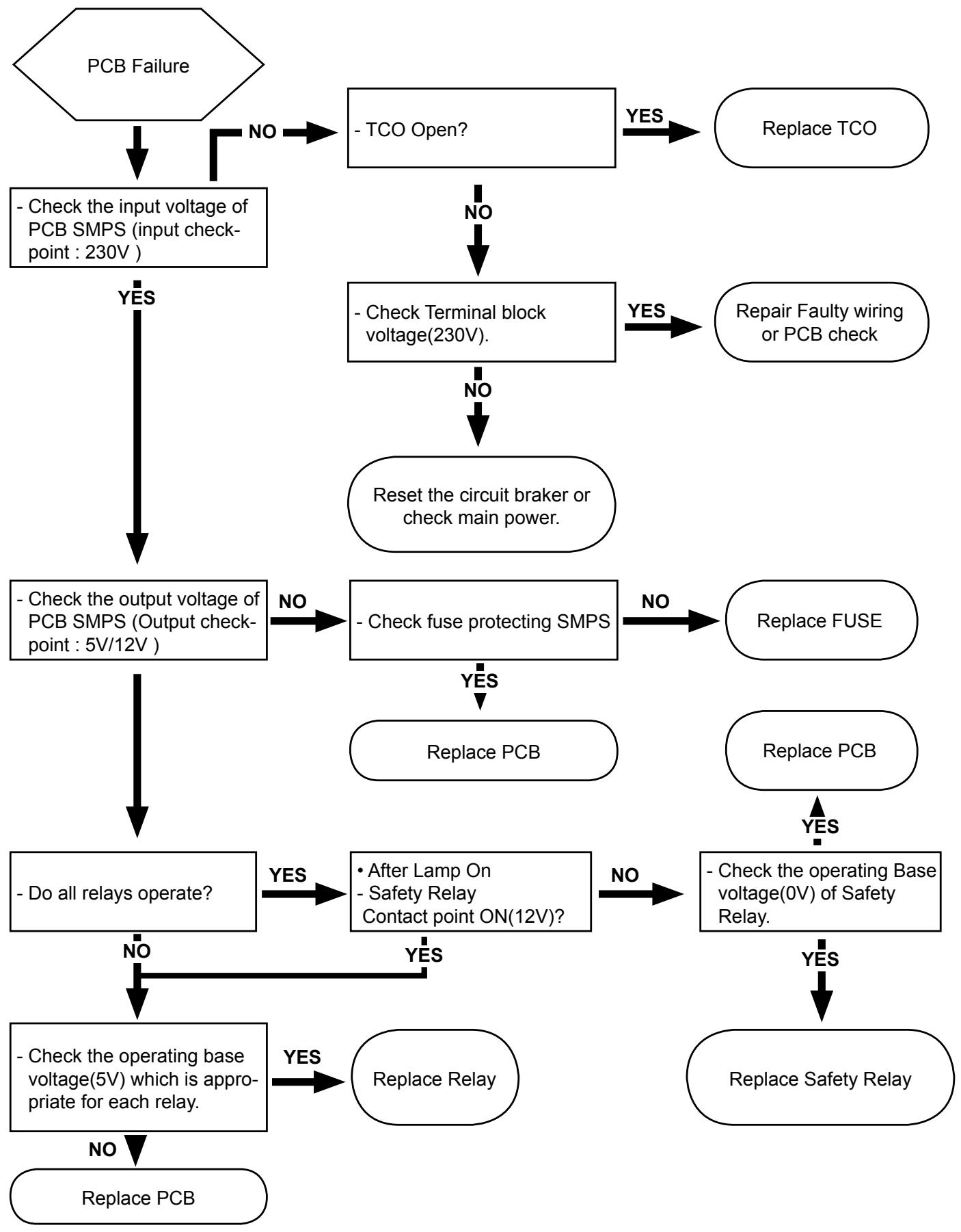
flowchart
graph TD
    A["PCB Failure"] -->|NO| B["- Check the input voltage of PCB SMPS (input checkpoint: 230V)"]
    B -->|YES| C["- Check the output voltage of PCB SMPS (Output checkpoint: 5V/12V)"]
    C -->|NO| D["- Check fuse protecting SMPS"]
    D -->|YES| E["- Replace PCB"]
    D -->|NO| F["- Check Terminal block voltage(230V)."]
    F -->|YES| G["Repair Faulty wiring or PCB check"]
    F -->|NO| H["Reset the circuit broker or check main power"]
    H --> I["- Do all relays operate?"]
    I -->|YES| J["• After Lamp On - Safety Relay Contact point ON(12V)?"]
    J -->|NO| K["- Check the operating base voltage(0V) of Safety Relay."]
    K -->|YES| L["Replace Safety Relay"]
    K -->|NO| M["- Check the operating base voltage(5V) which is appropriate for each relay."]
    M -->|YES| N["Replace Relay"]
    M -->|NO| O["Replace PCB"]
    O --> P["End"]
4-1-16 Failure of heating elements
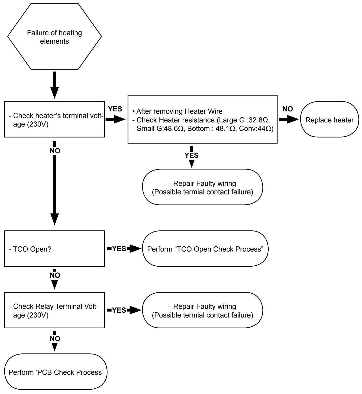
flowchart
graph TD
    A["Failure of heating elements"] --> B["- Check heater's terminal voltage (230V)"]
    B -->|YES| C["After removing Heater Wire\n- Check Heater resistance (Large G :32.8Ω,\nSmall G:48.6Ω, Bottom : 48.1Ω, Conv:44Ω)"]
    B -->|NO| D["- TCO Open?"]
    C -->|YES| E["Repair Faulty wiring\n(Possible terminal contact failure)"]
    C -->|NO| F["- Check Relay Terminal Voltage (230V)"]
    E --> G["Perform 'TCO Open Check Process'"]
    F --> H["Perform 'PCB Check Process'"]
    G --> I["Repair Faulty wiring\n(Possible terminal contact failure)"]
    H --> I
5. Exploded Views and Parts List
5-1 Exploded Views
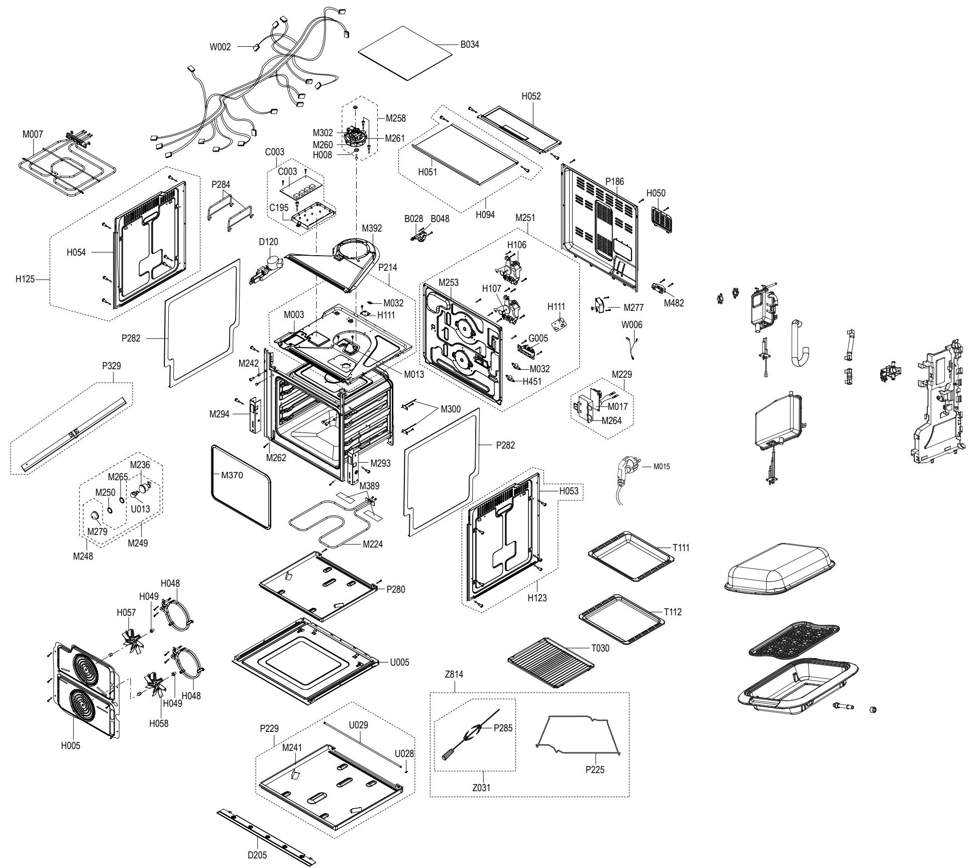
text_image
Exploded view diagram of a refrigerator assembly with labeled components such as M007, H054, and P284.5-2 Main Parts List
(SNA : SERVICE NOT AVAILABLE)
| No. | Code No. | Description | Specification | Q'ty | SA/ SNA | Remark | |
5-2 Main Parts List
| No. | Code No. | Description | Specification | Q'ty | SA/ SNA | Remark | |
5-3 Door Parts List
D049
ASSY DOOR
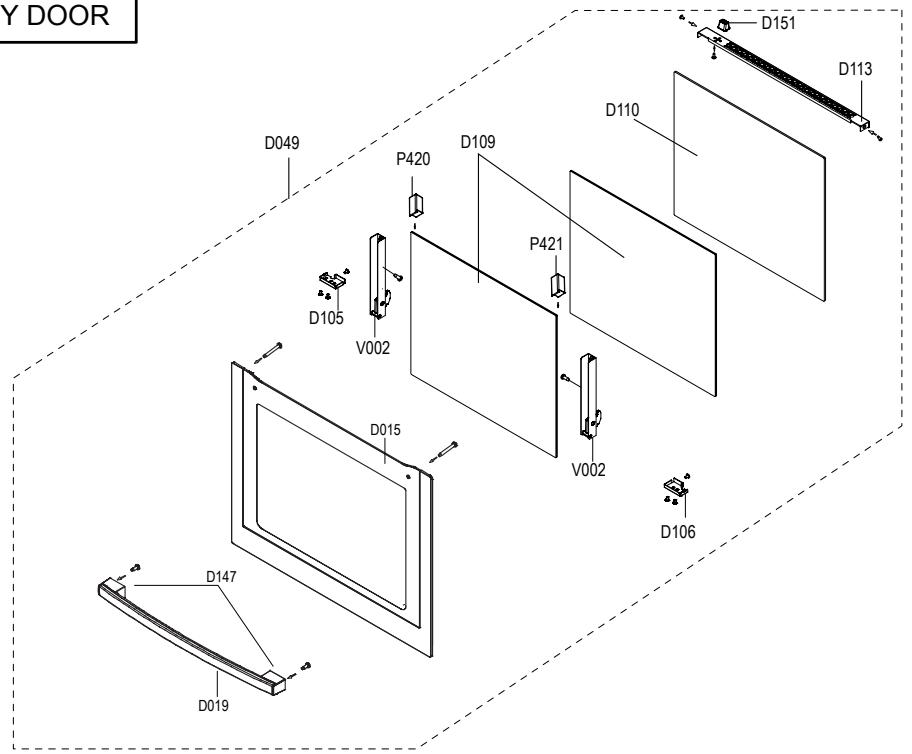
text_image
Y DOOR D049 P420 D109 D110 D151 D113 D105 V002 P421 D015 V002 D106 D147 D019(SNA : SERVICE NOT AVAILABLE)
| No. | Code No. | Description | Specification | Q'ty | SA/SNA | Remark |
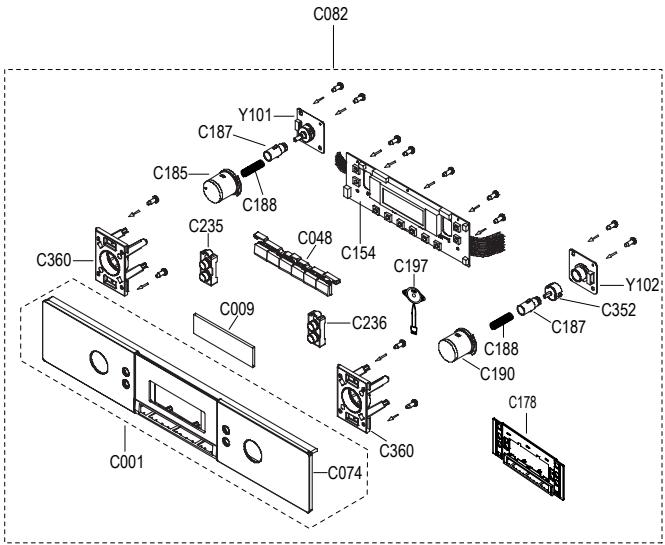
5-4 Control Parts List
C082
ASSY CONTROL-BOX
| No. | Code No. | Description | Specification | Q'ty | SA/ SNA | Remark | |
5-5 Standard Parts List
(SNA : SERVICE NOT AVAILABLE)
| LEV-EL | Code No. | Description | Specification | Q'ty | SA/ SNA | Remark | |
6. PCB Diagram
6-1 PCB Diagram
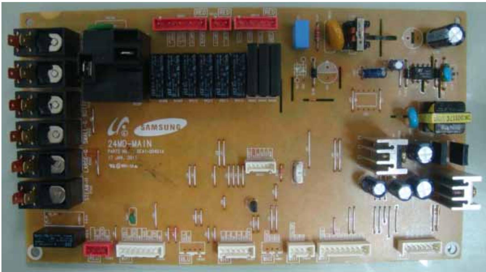
natural_image
Top-down view of a Samsung 24MD-MAIN printed circuit board with various electronic components and connectors (no readable text or symbols beyond branding)| No. | Parts Number | Part Name | Function and Rule | No. | Parts Number | Part Name | Function and Rule |
| 1 | CN101 | Display connector-1 | A Terminal for Connecting with display module. | 12 | RY104 | Upper heater Relay | A relay for Connecting with Upper heater |
| 2 | CN102 | Display connector-2 | A Terminal for Connecting with display module. | 13 | RY105 | Lower heater Relay | A relay for Connecting with Lower heater |
| 3 | CN103 | Temp sensor & divider switch connector | A Terminal for Connecting with divider and temp sensor. | 14 | RY106 | Latch open Relay | Latch open control |
| 4 | CN104 | Buzzer | A Terminal for Connecting with speaker. | 15 | RY107 | Latch close Relay | Latch close control |
| 5 | CN105 | Door Lock motor connector | A Terminal for Connecting with Door Lock motor. | 16 | RY108 | Uppwe lamp Relay | Uppwe lamp control |
| 6 | CN106 | Neutral, upper/lower lamp | A Terminal for Connecting with Neutral,upper/lower lamp. | 17 | RY109 | Lower lamp Relay | Lower lamp control |
| 7 | CN107 | Spit, Upper/lower fan, Cooling fan | A Terminal for Connecting with Spit, Upper/lower fan, Cooling fan. | 18 | RY111 | Spit Relay | Spit Source |
| 8 | CN108 | Door latch, Door sensing | A Terminal for Connecting with Door latch, Door sensing | 19 | RY112 | Source Relay | Supply power for all relay |
| 9 | RY101 | Large grill Relay | A relay for Connecting with Large grill heater | 20 | SSR101 | Upper fan SSR | Upper fan control |
| 10 | RY102 | Small grill Relay | A relay for Connecting with Small grill heater | 21 | SSR102 | Lower fan SSR | Lower fan control |
| 11 | RY103 | Bottom heater Relay | A relay for Connecting with Bottom heater | 22 | SSR103 | Cooling fan SSR | Cooling fan control |
7. Wiring Diagram (This Document can not be used without Samsung's authorization.)
7-1 Wiring Diagram
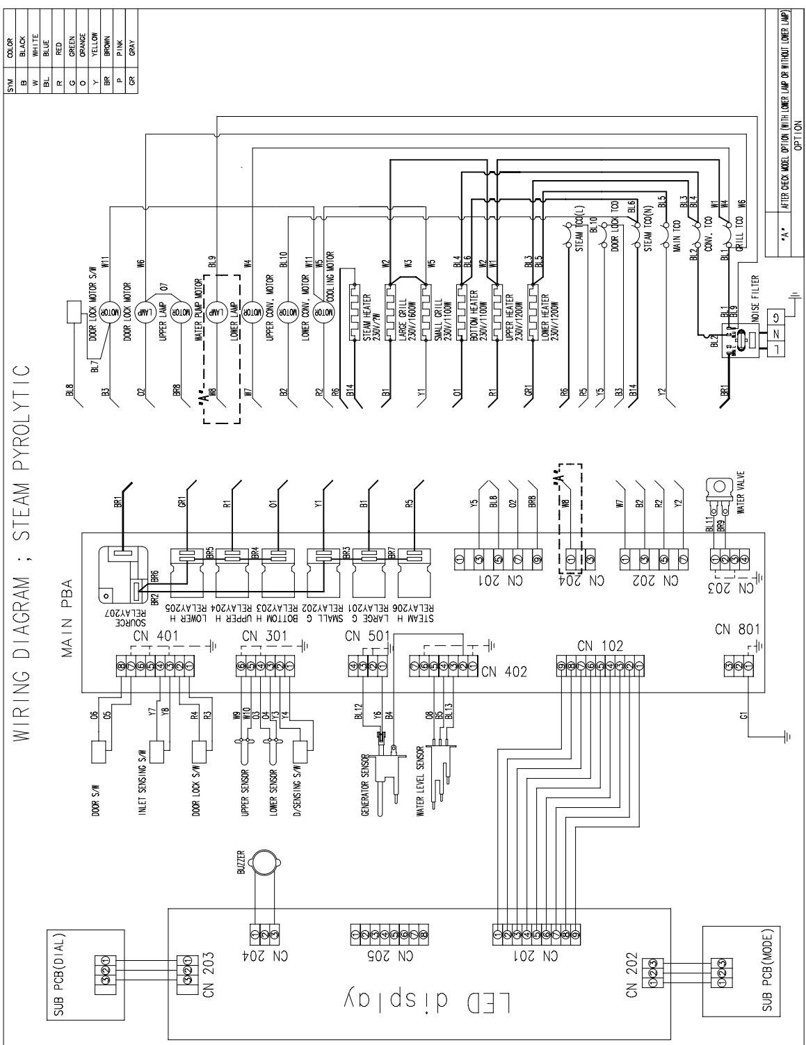
text_image
WIRING DIAGRAM ; STEAM PYROLYTIC SUB PCB(DIAL) CN 203 BUZER CON 204 LED display CN 205 CON 201 CN 202 SUB PCB(MODE) MAIN PBA DOOR S/W O6 O5 INLET SENSING S/W Y7 Y8 DOOR LOCK S/W R4 R3 UPPER SENSOR W9 W10 LOWER SENSOR D/SENSING S/W N3 N4 N5 SEMAH H LARGE G RELAY201 G S/SEMAH S/W BBL12 Y6 B4 GENERATOR SENSOR BL13 W8 BL13 W10 W11 W12 W13 W14 W15 W16 W17 W18 W19 W20 W21 W22 W23 W24 W25 W26 W27 W28 W29 W30 W31 W32 W33 W34 W35 W36 W37 W38 W39 W40 W41 W42 W43 W44 W45 W46 W47 W48 W49 W50 W51 W52 W53 W54 W55 W56 W57 W58 W59 W60 BL8 BL7 BR1 BR2 BR6 GR1 BR5 BR4 R1 O1 Y1 BR3 B1 BR7 R5 STEAM H LARGE G RELAY201 RELAY206 RELAY201 STEAM H LARGE G RELAY201 RELAY206 RELAY201 STEAM H LARGE G RELAY201 RELAY206 RELAY201 STEAM H LARGE G RELAY201 RELAY206 RELAY201 STEAM H LARGE G RELAY201 RELAY206 RELAY201 STEAM H LARGE G RELAY2018. Schematic Diagram
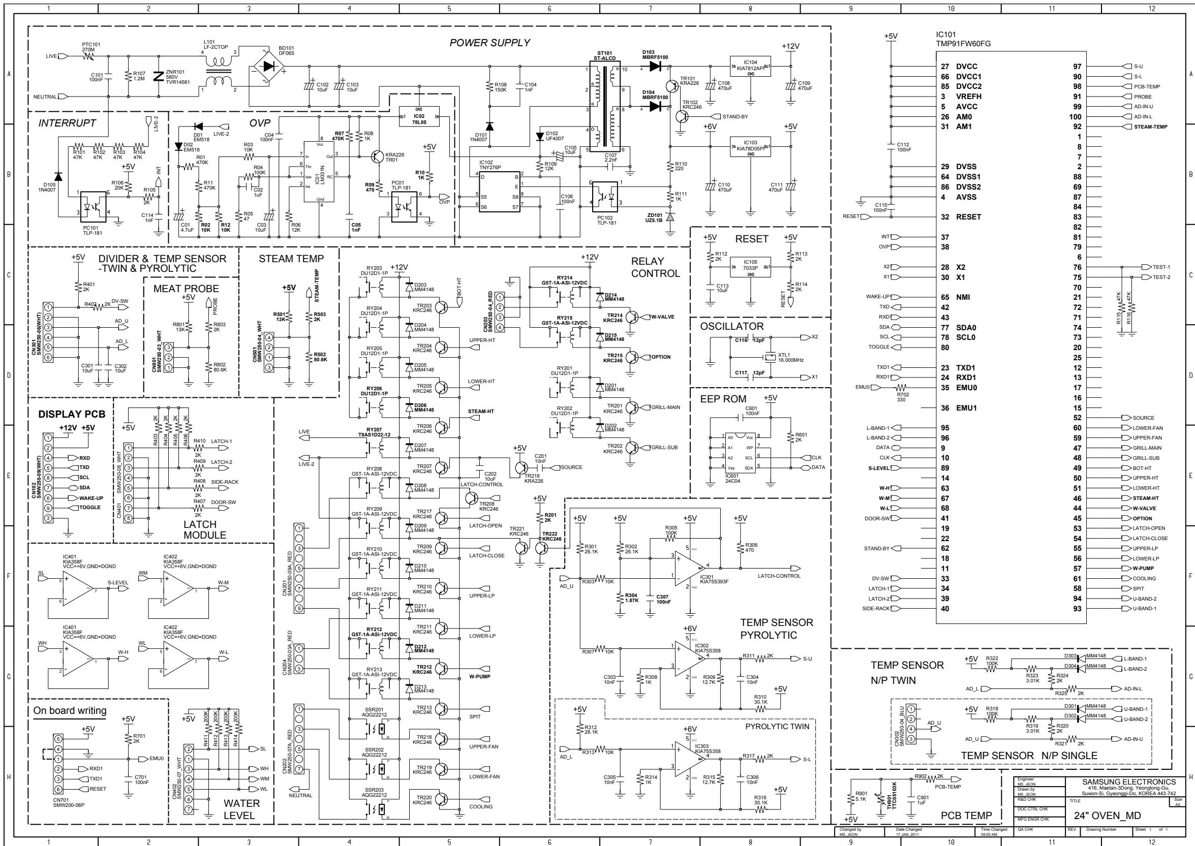
8-1 Schematic Diagram
SAMSUNG
GSPN (Global Service Partner Network)
| Contry | Web Site |
| North America | service.samsungportal.com |
| Latin America | latin.samsungportal.com |
| CIS | cis.samsungportal.com |
| Europe | europe.samsungportal.com |
| China | china.samsungportal.com |
| Asia | asia.samsungportal.com |
| Mideast & Africa | mea.samsungportal.com |