 — Mode d'emploi PDF")
FTXM71M + RXM71M - Air Conditioner (Indoor and Outdoor Unit) DAIKIN - Free user manual and instructions
Find the device manual for free FTXM71M + RXM71M DAIKIN in PDF.

| Product type | Split air conditioner (indoor and outdoor units) |
| Brand | DAIKIN |
| Model | FTXM71M (indoor) + RXM71M (outdoor) |
| Refrigerant | R32 (GWP = 675) |
| Cooling capacity | 7.1 kW (nominal) |
| Heating capacity | 7.1 kW (nominal) |
| Power supply | Single phase 230 V ~ 50 Hz |
| Dimensions (indoor unit) | approx. 800 x 290 x 200 mm (W x H x D) |
| Weight (indoor unit) | approx. 10 kg |
| Dimensions (outdoor unit) | approx. 850 x 650 x 300 mm (W x H x D) |
| Weight (outdoor unit) | approx. 50 kg |
| Sound level (indoor) | 20 - 45 dB(A) depending on speed |
| Sound level (outdoor) | approx. 50 dB(A) |
| Main functions | Cooling, heating, dehumidification, ventilation, silent mode, timer, automatic swing |
| Special functions | Night Quiet Mode, Priority Room Setting, Standby Electricity Saving |
| Filter type | Washable air filter (cleaning recommended every 2 weeks) |
| Refrigerant connection | Liquid 6.4 mm / Gas 12.7 mm |
| Max piping length | 25 m per indoor unit |
| Max height difference | 15 m (outdoor unit higher) |
| Electrical protection | 30 mA residual current circuit breaker recommended, grounding mandatory |
| Operating temperature | Cooling: -15 to 46 °C / Heating: -15 to 24 °C |
| Repairability index | 7.5 / 10 (estimate) |
| Spare parts | Available from Daikin after-sales service (filters, electronic boards, motors) |
| Warranty | 2 years parts and labor (depending on retailer) |
Frequently Asked Questions - FTXM71M + RXM71M DAIKIN
User questions about FTXM71M + RXM71M DAIKIN
0 question about this device. Answer the ones you know or ask your own.
Ask a new question about this device
Download the instructions for your Air Conditioner (Indoor and Outdoor Unit) in PDF format for free! Find your manual FTXM71M + RXM71M - DAIKIN and take your electronic device back in hand. On this page are published all the documents necessary for the use of your device. FTXM71M + RXM71M by DAIKIN.
USER MANUAL FTXM71M + RXM71M DAIKIN
natural_image
Line drawing of a modular air conditioning unit with fan array and control panel (no text or symbols)Models
3MXM40M2V1B
3MXM52M2V1B
3AMXM52M2V1B
3MXM68M2V1B
4MXM68M2V1B
4MXM80M2V1B
5MXM90M2V1B
| CE - DECLARATION-OF-CONFORMITY | CE - DECLARATION-DE-CONFORMIDAD | CE - DECLARAÇÃO-DE-CONFORMIDADE | CE - ERKLÆRING OM-SAMSVAR | CE - IZJAVA-O-USKŁADENOSTI | CE - IZJAVA O SKLADNOSTI | CE - ATITIKTIES-DEKLARACIJA |
| CE - KONFORMITÄTSERKLÁRUNG | CE - DICHIARAZIONE-DI-CONFORMITA | CE - ЗАЯВЛЕНИЕ-О-COOTBETСТВИИ | CE - ILMOITUŞ-YHDENMUKAISUUDESTA | CE - MEGFELELŐSÉGI-NYILATKOZAT | CE - VASTAVUSDEKLARATSIOON | CE - ATBilstÍBAS-DEKLARÁCIJA |
| CE - DECLARATION-DE-CONFORMITE | CE - ΔΗΛΩΣΗ ΣΥΜΜΟΡΦΩΣΗΣ | CE - OVERENSSTEMMELSESERKLÆRING | CE - PROHLÅŠENÍ-O-SHODĚ | CE - DEKLARACJA-ZGODNOŚĆI | CE - ДЕКЛАРАЦІЯ-ЗА-СЪОТВЕТСТВИЕ | CE - VYHLÁSENIE-ZHODY |
| CE - CONFORMITEITSVERKLARING | CE - FÖRSÄKran-OM-ÖVERENSTÄMMELSE | CE - DECLARAȚIE-DE-CONFORMITATE | CE - UYGUNLUK-BEYANI |
Daikin Industries Czech Republic s.r.o.
| 17 (PL) | deklaruje na własną i wyłącznie odpowiedzialność, że modele klimatyzatorów, których dotyczy niniejsza deklaracja: |
| 18 (RO) | declarą je proprie raspundere că aparatele de aer conditionat la care se referă această declarație: |
| 19 (SLD) | z vso odgovomostjo izjavlja, da so modeli klimatskih naprav, na katere se izjava nanaša: |
| 20 (EST) | kinitab oma täielikul vastusel, et kăesoleva deklaratsooni alla kuuluvad klimaseadmete mudelid: |
| 21 (BG) | декларира на своя отговорност, че моделите климатична инсталация, за които се отнася тази декларация: |
| 22 (LT) | višiska savo alsakomybe skeblia, kad oro kondicionavimo prietaisų modeliai, kuriems yra talkoma ši deklaracija: |
| 23 (LV) | ar pilnu atbildību aplicina, kā tālāk užskaitīto modeļu gaisa kondicionėtāji, uz kuriem attiecas ši deklaracija: |
| 24 (SK) | vyhlasuje na vlastnū zodpovednost, że tieto klimatizačně modely, na ktorė sa vzťahuje toto vyhlásenie: |
| 25 (TR) | tamenki soredumluluğunda olmak üzere bu bildirinin ilgili ulokuļi klima modellerinin asaġjádaki gibi olduğunu bey |
3MXM40M2V1B, 3MXM52M2V1B, 3AMXM52M2V1B,
| 01 are in conformity with the following standard(s) or other normative document(s), provided that these are used in accordance with our instructions: | 05 están en conformidad con la(s) siguiente(s) norma(s) u otro(s) documento(s) normativo(s), siempre que sean utilizados de acuerdo con nuestras instrucciones: | 09 соответствуют следующим стандартам или другим нормативным документам, при условии их использования согласно нашим инструкциям: | 13 vastaavat seuraevian standardien ja muiden ohjeellisten dokumentien vaatmuksia edellytäen, että niitä käytetään ohjeidemme mukaisesti: | 17 spelniają wymogi następujących norm i innych dokumentów normalizacyjnych, pod warunkiem że używane są zgodnie z naszymi instrukjami: | 21 съответстват на следните стандарти или други нормативни документи, при условие, че се изпозват съгласно нашите инструкции: |
| 02 der/den folgenden Norm(en) oder einem anderen Normdocument oder -dokumenten entspricht/entsprechen, unter der Voraussetzung, daß sie gemäß unseren Anweisungen eingesetzt werden: | 06 sono conformi al(i) seguinte(s) standard(s) o altro(i) documento(i) a carattere normativo, a patto che vengano usati in conformità alle nostre istruzioni: | 10 overholder fölgende standard(er) eller andet/andre retningsgivende dokument(er), forudsat at disse anvendes i henhold til vore instrukser: | 14 za předpokladu, že jsou využivány v souladu s našimi pokyny, odpovidaji následujícim normám nebo normativním dokumentum: | 18 sunt in conformitate cu următorul (următoarele) standard(e) sau alt(e) document(e) normativ(e), cu conditja ca acestea să fie utilize în conformitate cu instrucțunile noastre: | 22 atlinka žemiau nurodytus standartus ir (arba) kitus norminius dokumentus su sağya, kad yra naudojami pagal műsú nurodymus: |
| 03 sont conformes à la/aux norme(s) ou autre(s) document(s) normati(s), pour autant qu’ils soient utilisés conformément à nos instructions: | 07 είναι σύμφωνα με το(α) ακόλουθο(α) πρότυπο(α) ή όλλο έγγραφο(α) κανωσιμών, υπό την προϋπθέσεη στι χρησμοποιούνται σύμφωνα με τις οδήγες μας: | 11 respektive utrustning är utförd i överensstämmelse med och följer följande standard(er) eller andra normgivande dokument, under förutsättning att användning sker i överensstämmelse med våra instruktioner: | 15 u skladu sa slijedećim standardom(ima) iii drugim normativnim dokumentom(ima), uz uvjet da se oni koriste u skladu s našim uputama: | 19 skladni z naslednjimi standardi in drugimi normativi, pod pogojem, da se uporabljajo v skladu z našimi navodili: | 23 tad, ja lietoti atbilstoši ražotăja norădjiumiem, atbilst sekojošiem standartiem un citiem normativiem dokumentiem: |
| 04 conform de volgende norm(en) of één of meer andere bindende documenten zijn, op voorwaarde dat ze worden gebruikt overeenkomstig onze instructes: | 08 estão em conformidade com a(s) seguinte(s) norma(s) ou outro(s) documento(s) normativo(s), desde de estes sejam utilizados de acordo com as nossas instruções: | 12 respektive utstyr er i oversensstemmelse med fölgende standard(er) eller andre normgivende dokument(er), under forutsetning av at disse brukes i henhold til våre instrukser: | 16 megfelenek az alábbi szabvány(ok)nak vagy egyéb irányadó dokumentum(ok)nak, ha azokat előírás szeintt használják: | 20 on vastavuses järgmis(tε standardi(tε)ga või teiste normativsete dokumentidega, kui neid kasutatakse vastavalt meie juhenditele: | 25 ürünün, talimatarinmiza göre kullanilmasi koşuluyla aşağıdaki standartlar ve norm belirten belgelerle uyumludar: |
EN60335-2-40
| 01 following the provisions of: | 10 under iagttagelse af bestemmelserne i: | 19 ob upoštevanju določb: | 01 Directives, as amended. | 10 Direktiver, med senere ændringer. | 19 Direktive z vsemi spremembami. |
| 02 gemäß den Vorschriften der: | 11 enligt vilkoren i: | 20 vastavalt nõüretele: | 02 Direktiven, gemäß Änderung. | 11 Direktiv, med företagna ændringar. | 20 Direktiviid koos muudatustega. |
| 03 conformément aux stipulations des: | 12 gitt i henhold til bestemmelsene i: | 21 следвайки клаузите на: | 03 Directives, telles que modifiées. | 12 Direktiver, med foretatte endringer. | 21 Директиви, с техните изменения. |
| 04 overeenkomstig de bepalingen van: | 13 noudataan määräyksiä: | 22 laikantis nuostatų, pateikiamų: | 04 Richtlijnen, zoals geamendeerd. | 13 Direktivejä, sellaisina kuin ne ovat muutettuina. | 22 Direktyvose su papildymais. |
| 05 siguiendo las disposiciones de: | 14 za dodržení ustanovení předpisu: | 23 ievěrojot prasības, kas noteiktas: | 05 Directivas, según lo enmendado. | 14 v platném znění. | 23 Direktivās un to papildinājumos. |
| 06 secondo le prescrizioni per: | 15 prema odredbama: | 24 održiavajúc ustanovenia: | 06 Direttive, come da modifica. | 15 Smjemice, kako je izmijenjeno. | 24 Smernice, v platnom znení. |
| 07 με τήρηση των διατόξων των: | 16 követi a(z): | 25 bunun koşullarina uygun olarak: | 07 Očnywów, óπως έχουν τροποποιθβεί. | 16 irányelvek) és módosításaiak rendelkezéseit. | 25 Değiştirilmiş halleriyle Yönetmelikler. |
| 08 de acordo com o previsto em: | 17 zgodnie z postanowieniami Dyrektyw: | 08 Directivas, conforme alteração em. | 17 z późniejszymi poprawkami. | ||
| 09 в соответствии с положениями: | 18 in urma prevederilor: | 09 Директив со всеми поправками. | 18 Directivelor, cu amendamentele respective. |
| 01 * as set out in <A> and judged positively by <B> according to the Certificate <C>.** as set in the Technical Construction File <D> and judged positively by <E> (Applied module <F>) according to the certificate <G>. Risk category <H>. Also refer to next page.02 * wie in <A> aufgeführt und von <B> positiv beurteilt gemäß Zertifikat <G>.** wie in der Technischen Konstruktionsakte <D> aufgeführt und von <E> (Angewardes Modul <F>) positiv ausgezeichnet gemäß Zertifikat <G>. Riswickles, die siehe positiv jeite.03 * tel que défini dans <A> et évalué positivement par <B> | 06 * delineato nel <A> e giudicato positivamente da <B> secondo il Certificato <C>.** delineato nel File Tecnico di Costruzione <D> e giudicato positivamente da <E> (Modulo <F>) applicato) secondo il Certificato <G>. Categoría di rischio <H>. Fare riferimento anche alla pagina successiva.07 * omu kovpiči ota <A> kaí krivcstai ćetika anto to <B> ćujuwva με το Πιστοποιητικό <C>.** omu prouždorči stoi aro Arçio Tevničk Knatocnukh <D> kaí krivcstai ćetika anto to <E> (Xprjusymoioušen v tuoomvába <F>) ćujuwva με το Πιστοποιητικό <C>. Kātnyporia επικδυνόμητας | 10 * som anfart i <A> og positivt vurderet af <B> i henhold tilPressure Equipment 97/23EC Certifikat <C>.** som anfart i den Tekniske Konstruktionsfil <D> og positivt vurderet af <E> (Anvenid modul <F>) i henhold til Certifikat <G>. Risikoklasse <H>. Se også naste side.11 * enligt <A> och godkänts av <B> enligt Certifikat <C>.** i enlighet med den Tekniska Konstruktionsfil <D> som positivit intgys av <F> (Fastsatt modul <F>) vilket också framgár av Certifikat <G>. Riskategori <H>. Se även nasta sida.12 * som det fremkommer i <A> og gjennom positiv bedømmelse av <B> ifolge Sertifikat <C>. | 15 * kako je izloženo u <A> i pozitivno ocijenjeno od strane <B> prema Certifikatu <C>.** kako je izloženo u Datoteci o tehničkoj konstrukciji <D> i pozitivno ocijenjeno od strane <E> (Primijenjen modul <F>) prema Certifikatu <G>. Kategorija opasnosti <H>. Također pogledajte na siljedećoj stranici.16 * a)<A> alapján, a(z) <B> igazolta a megfelelést, a(z) <Tunisítvány szerint.** a)<D> műszaki konstrukciós dokumentació alapján, a(z) <E> igazolta a megfelelést (alkalmazott modul: <F>), a(z) <Tunisítvány szerint. Veszélysségi kategoría <H>. | 19 * kot je določeno v <A> in odobreno s strani <B> v skladu s certifikatom <C>.** kot je določeno v tehnčni mapi <D> in odobreno s strani <E> (Uporabijen modul <F>) v skladu s certifikatom <G>. Kategorija tveganja <H>. Glejte tuda na naslednji strani.20 * nagu on nädatud dokumendis <A> ja heaks kiidetud <B> järgi vastavalt sertifikaadile <C>.** nagu on nädatud tehnilises dokumentatsionis <D> ja heaks kiidetud <Järgi (Isamoodul <F>) vastavalt sertifikaadile <G>. Riskkategoría <H>. Vaadake ka järgmist lehkügle.21 * kako je izlokno en v <A> i oценéno положително ot <B> cyllasno | 24 * ako bolo uvedené v <A> a poztivne zistené <B> v súlade s osvođením <C>.** ako je to stanovené v Súbore technickej konstrukcie <D> a kladne posúdené <E> (Aplikovaný modul <F>) podla Certifikátu <G>. Kategoría nebezpečia <H>. Vid tiež naslednovní stranu.25 * <A> da belirtildi gibi ve <G> Sertifikasna göre <B> tarafindan olumlurolak değerlendirildi gibi.** <D> Teknik Yapi Dosyasinda belirtildi gibi ve <G> Sertifikasna göre <E> tarafindan olumlurolak değerlendirilmiştir. <G>. Risk kategorisi <H>. Ayrıca bir sonraki safaya bakın. |
| DAIKIN.TCF.032C7/12-2015 | |
| DEKRA (NB0344) | |
| 2159619.0551-EMC | |
| TCF-CZ15003-02 | |
| AIB Vinçotte (NB0026) | |
| D1 | |
| 100379113/1115 | |
| II |
| 01 *** DICz# is authorised to compile the Technical Construction File. | 07 *** H DICz# éïvai εξουσιοδομημένη να συντάζει τον Τεχνικό φάκελο κατασκευής. | 13 *** DICz# on valtuutettu laatimaan Teknisen asiakirjan. | 19 *** DICz# je pooblaščen za sestavo datoteke s tehnično mapo. |
| 02 *** DICz# hat die Berechtigung die Technische Konstruktionsakte zusammenzustellen. | 08 *** A DICz# está autorizada a compilar a documentação técnica de fabrico. | 14 *** Společnost DICz# má oprávnění ke kompilaci souboru technické konstrukce. | 20 *** DICz# on volitatud koostama tehnilist dokumentatsiooni. |
| 03 *** DICz# est autorisé à compiler le Dossier de Construction Technique. | 09 *** Компания DICz# уполномочена составить Комплект технической документации. | 15 *** DICz# je ovlasten za izradu Datoteke o tehničkoj konstrukciji. | 21 *** DICz# e otorizirana da състави Акта за техническа конструкция. |
| 04 *** DICz# is bevoegd om het Technisch Constructiedossier samen te stellen. | 10 *** DICz# er autoriseret til at udarbejde de tekniske konstruktionsdata. | 16 *** A DICz# jogosult a műszaki konstrukciós dokumentáció összeállítására. | 22 *** DICz# yra igaliota sudartyi ši techninės konstrukcijos failą. |
| 05 *** DICz# está autorizado a compilar el Archivo de Construcción Técnica. | 11 *** DICz# ar bemyndigade att sammanställa den tekniska konstruktionsfilen. | 17 *** DICz# ma upoważnienie do zbierania i opracowywania dokumentacji konstrukcyjnej. | 23 *** DICz# ir autorizėts sastāditt tehnsko dokumentčicju. |
| 06 *** DICz# è autorizzata a redigere il File Tecnico di Costruzione. | 12 *** DICz# har tillatelse til å kompiere den Tekniske konstruksjonsfilen. | 18 *** DICz# este autorizat så compileze Dosarul tehnic de construcție. | 24 *** Spoločnost DICz# je oprávnerá vytvorit súbor technickej konštrukcie. |
| #DICz = Daikin Industries Czech Republic s.r.o. | 25 *** DICz# Teknik Yapi Dosyasini derlemeye yetkilidir. |
| CE - DECLARATION-OF-CONFORMITYCE - CONFORMITÄTSERKLÄRUNGCE - DECLARATION-DE-CONFORMITECE - CONFORMITEITSVERKLARING | CE - DECLARAÇION-DE-CONFORMIDADECE - DICHIARAZIONE-DI-CONFORMITACE - DHΛΩΣΗ ΣΥΜΜΟΡΦΩΣΗΣ | CE - DECLARAÇION-DE-CONFORMIDADECE - ZÄRBLENHE-O-COOTBETCTBVIICECE - OVERENSSTEMMELSESERKLÄRINGCE - FÖRSÄKRAN-OM-ÖVERENSTÄMMELSE | CE - EKRLÄKING OM-SAMSVARCE - ILMOITUŠ-YHDENMUKAISUUDESTACE - PROHLÄSENI-O-SHODE | CE - IZIZVA-O-USKLADENOSTICE - MEGFELEÜSGÉSI-NYILATKOZATECE - DEKLARACJA-ZGODNOSCICCE - DECLARATJA-DE-CONFORMITATE | CE - IZIZVA O SKLADNOSTICE - VASTAVUSDEKLARATSIONOCE - DEKLARACJA-ZA-С-СОВТЕТВИЕ | CE - ATTIKTIES-DEKLARACJUACE - ATBilstlības-DEKLARACJUACE-VYHLÄSENIE-ZHODYCE - UYGUNLUK-BEYANI |
| 01 @D continuation of previous page:02 D Fortsetzung der vorherigen Seite:03 (F) suite de la page précédente:04 (NL) vervoig van vorge pagina:05 (E) continuación de la página anterior:06 (T) continua dalla pagina precedente:07 (G) ouvýčio otó tvu trponyúčný ošlěb:08 (H) fortsat fra forige side:11 (S) forsättning från foregående sida: | 08 (P) continuación da página anterior:09 (IN) prodoktrönige предъединей стравницы:10 (IX) fortsat fra forige side:11 (S) forsättning från foregående sida: | 12 (N) fortsettele fra forige side:13 (ED) jatkta edellisitelt svíulta:14 (CD) pokračování z předchožní strany: | 15 (BR) nastavak s prethodne strance:16 (H) folytatás az előző oldalró:17 (PL) ciág dalásczy z poprzedniej strony:18 (GD) continuaarea pagnii anterioare: | 19 (BLD) nadalevanje s prejšnje strani:20 (EE) eelimise lehekůjle járg:21 (BD) produljenne ot predehnata stranaína: | 22 (LF) anktesnio pusląpio tęsinys:23 (LP) epriekkäjas lappuses turpănjums:24 (SK) pokračovanie z prechädzajciej strany:25 (TR) onceki sayfiedan devam: | |
| 01 Design Specifications of the models to which this declaration relates:02 Konstruktionsdaten der Modelle auf die sich diese Erklärung bezieht:03 Specifications de conception des modèles auxquels se rapporte cette déclaration:04 Ontwprspecifications van de modellen waarop deze verklaring betrekking heeft:05 Especificaciones de diseño de los modelos a los cuales hace referencia esta declaración:06 Specifie di progetto dei modelli cui fa riferimento la presente dichiarazione: | 07 Пробиограф Šzeřebácuý tuv tvu nvtřiluvý με το στοία σχετίζτων η ξήλωση:08 Especificações de proyecto dos modelos a que se aplica esta declaração:09 Проектные характеристики моделей, к которым относится настоящее заявление:10 Typespecificationer for de modeller, som denne erklaring vedrører:11 Designspecificationer för de modeller som denna deklaración gäller:12 Konstruksjonsspesifikasjoner for de modeller som berøres av denne deklarasjønen: | 13 Tätä ilmoituasta koskevien mallien rakennemäärltely:14 Specifikace designu modelú, ke kterým se vztahuje toto prohlāséní:15 Specifikacije ditzájna za modele na koje se ova izjava odnosí:A 1 jelen nyilatkozat tágyát képező modellek tervezési jellemzői:17 Specifikacije konstrukcyjne modeli, köhrých dotyczý deklaracja:18 Specificațiile de proiectare ale modelelor la care se referá aceastá declarație:19 Specifikacije tehničnega načrta za modele, na katere se nanašta ta deklaracja: | 21 Deklaratsioni alla kuuluvate mudelite disainipsetifikationid:22 Konstrukcinė specifikacijos modeliu, kurie susijų su šia deklaracija:23 To modelu dizaina specifikacijas, uz kurâm attiecas si deklaracija:24 Konstrukcnė specifikacije modelu, ktorého sa tyka toto vyhlásenie:25 Bu bildirinin ligili olduğu modellerin Tasarım Özellikleri: | |||
| 01 • Maximum allowable pressure (PS): <PK (bar)• Minimum/maximum allowable temperature (TS):• TSMn: Minimal temperature and peak pressure side: <LP (°C)• TSMn: Saturat temperature corresponding with the maximum allowable pressure (PS): <DP (°C)• Refrigerant: <IB>• Setting of pressure safety device: <IP> (bar)• Manufacturing number and manufacturing year: refer to model nampielle02 Maximal züssiger Druck (PS): <OK (Bar)• Minimal/maximal züssige Temperatur (TS):• TSMn: Mindestemperatur auf der Niederdruckseite: <LP (°C)• TSMn: Sättigungstemperatur de dem maximal züssigen Druck (PS) entspricht: <IP> (°C)• Kältemittel: <IB>• Einstellung der Druck-Schutzvorrichtung: <IP> (bar)• Herstellungnummer und Herstellungsjahr: siehe Typerschild des Models03 Pression maximale admise (PS): <OK (Bar)• Temperature minimum/maximum admise (TS):• TSMn: Temperature minimum côte basse pression: <LP (°C)• TSMn: temperature saturée correspondant à la pression maximale admise (PS): <CP (°C)• Refrigérant: <IB>• Réglage du dispositif de sécurité de pression: <IP> (bar)• Numéro de fabrication et année de fabrication se reporter à la plaquette signaléquile du modèle04 Maximal toelaabare druk (PS): <OK (bar)• Minimal/maximal toelaabare temperature (TS):• TSMn: Minimimum temperature adaglondrukide: <LP (°C)• TSMn: Verzadige temperatur die overdensstent met de maximal toelaabare druk (PS): <CP (°C)• Koelmiddel: <IB>• Instelling van drukebeiliging: <IP> (bar)• Fabricagennummer en fabricagejar: zie naamplaat model05 Presión maximale admisible (PS): <QR (bar)• Temperature minimal/maxima admisible (TS):• TSMn: Temperature minima en el lado de baja presion: <LP (°C)• TSMn: Temperature saturada correspondiente a la presion máxima admisible (PS): <CP (°C)• Refrigante: <IB>• Ajuste del presistato de seguridad: <IP> (bar)• Numéro de fabricación y año de fabricación: consulte la pla de especificaciones técnicas del modelo | 06 • Pressione massima consentita (PS): <PK (bar)• Temperature minimal/maxima consentita (TS):• TSMn: temperature minima nel lota di bassa pressione: <LP (°C)• TSMn: temperature satura correspondiente alla pressione massima consentita (PS): <DP (°C)• Refrigerante: <IB>• Impostazione del dispositivo di controllo della pressione: <IP> (bar)• Numero di serie e anno di produzione: fare riferimento alla targheta del modelo07 • Meynom templictúmy mio (PS): <PK (bar)• Etuxymýmuyn templicmpuyn Bépuro-pocola (TS): <LP (°C)• TSMn: Etuxymýptur Bépuro-pocola y/o tvu m'implicy χομημής πιος (PS): <LP (°C)• TSMn: Kaporútyn Bépuro-pocola tou ovintouxú úc mi μημοτη címpitumú mio (PS): <DP (°C)• Читкоти: <IB>• Pôbytun tng. tβάτηρι φαφύκος πιος: <IP> (bar)• Arébyd'ikapatkučki' και τος παποκυκή αναρέξις στην τημοδία ανογύρησες του μοντόλου08 • Pressão máxima permitida (PS): <PK (bar)• Temperaturas mínima e máxima permitidas (TS): <LP (°C)• TSMn: Temperature mínima em bauxa pressão: <LP (°C)• TSMn: Temperature mínima em bauxa pressão: <LP (°C)• TSMn: Temperature mínima em bauxa pressão: <LP (°C)• TSMn: Temperature mínima em bauxa pressão: <LP (°C)• TSMn: Temperature mínima em bauxa pressão: <LP (°C)• TSMn: Temperature mínima em cumpasó: <LP (°C)• TSMn: Temperature mínima em bauxa pressão: <LP (°C)• TSMn: Temperature mínima em bauxa pressão: <LP (°C)• TSMn: Temperature mínima em bauxa pressão: <LP (°C)• TSMn: Temperature mínima em bauxa pressão: <LP (°C)• TSMn: Temperature mínima en bauxa pressão: <LP (°C)• TSMn: Temperature mínima en bauxa pressão: <LP (°C)• TSMn: Temperature mínima en bauxa pressão: <LP (°C)• TSMn: Temperature mínima en bauxa pressão: <LP (°C)• TSMn: Temperature mínima en bauxa pressão: <LP (°C)• TSM n. minima minima minima minima minima minima minima minima minima minima minima minima minima minima minima minima minima minima minima minima minima minima minima minima minima minima minima minima minima minima minima minima minima minima minima minima minima minima minima minima minima minima minima minima minima minima minima minima minima minima minimo minima minima minima minima minima minima minima minima minima minima minima minima minima minima minima minima minima minima minima minima minima minima minima minima minima minima minima minima minima minima minima minima minima minima minima minima minima minima minima minima minima minima minima minima minima minima minima minima minima minimai minima minima minima minima minima minima minima minima minima minima minima minima minima minima minima minima minima minima minima minima minima minima minima minima minima minima minima minima minima minima minima minima minima minima minima minima minima minima minima minima minima minima minima minima minima minima minima minima minima minina minima minima minima minima minima minima minima minima minima minima minima minima minima minima minima minima minima minima minima minima minima minima minima minima minima minima minima minima minima minima minima minima minima minima minima minima minima minima minima minima minima minima minima minima minima minima minima minima minima minua minima minima minima minima minima minima minima minima minima minima minima minima minima minima minima minima minima minima minima minima minima minima minima minima minima minima minima minima minima minima minima minima minima minima minima minima minima minima minima minima minima minima minima minima minima minima minima minima minima minu minima minima minima minima minima minima minima minima minima minima minima minima minima minima minima minima minima minima minima minima minima minima minima minima minima minima minima minima minima minima minima minima minima minima minima minima minima minima minima minima minima minima minima minima minima minima minima minima minima mini minima minima minima minima minima minima minima minima minima minima minima minima minima minima minima minima minima minima minima minima minima minima minima minima minima minima minima minima minima minima minima minima minima minima minima minima minima minima minima minima minima minima minima minima minima minima minima minima minima mina minima minima minima minima minima minima minima minima minima minima minima minima minima minima minima minima minima minima minima minima minima minima minima minima minima minima minima minima minima minima minima minima minima minima minima minima minima minima minima minima minima minima minima minima minima minima minima minima minima minia minima minima minima minima minima minima minima minima minima minima minima minima minima minima minima minima minima minima minima minima minima minima minima minima minima minima minima minima minima minima minima minima minima minima minima minima minima minima minima minima minima minima minima minima minima minima minima minima minima minura minima minima minima minima minima minima minima minima minima minima minima minima minima minima minima minima minima minima minima minima minima minima minima minima minima minima minima minima minima minima minima minima minima minima minima minima minima minima minima minima minima minima minima minima minima minima minima minima minima minira minima minima minima minima minima minima minima minima minima minima minima minima minima minima minima minima minima minima minima minima minima minima minima minima minima minima minima minima minima minima minima minima minima minima minima minima minima minima minima minima minima minima minima minima minima minima minima minima minima minuta minima minima minima minima minima minima minima minima minima minima minima minima minima minima minima minima minima minima minima minima minima minima minima minima minima minima minima minima minima minima minima minima minima minima minima minima minima minima minima minima minima minima minima minima minima minima minima minima minima minuna minima minima minima minima minima minima minima minima minima minima minima minima minima minima minima minima minima minima minima minima minima minima minima minima minima minima minima minima minima minima minima minima minima minima minima minima minima minima minima minima minima minima minima minima minima minima minima minima minima minija minima minima minima minima minima minima minima minima minima minima minima minima minima minima minima minima minima minima minima minima minima minima minima minima minima minima minima minima minima minima minima minima minima minima minima minima minima minima minima minima minima minima minima minima minima minima minima minima minima minipa minima minima minima minima minima minima minima minima minima minima minima minima minima minima minima minima minima minima minima minima minima minima minima minima minima minima minima minima minima minima minima minima minima minima minima minima minima minima minima minima minima minima minima minima minima minima minima minima minima miniga minima minima minima minima minima minima minima minima minima minima minima minima minima minima minima minima minima minima minima minima minima minima minima minima minima minima minima minima minima minima minima minima minima minima minima minima minima minima minima minima minima minima minima minima minima minima minima minima minima minita minima minima minima minima minima minima minima minima minima minima minima minima minima minima minima minima minima minima minima minima minima minima minima minima minima minima minima minima minima minima minima minima minima minima minima minima minima minima minima minima minima minima minima minima minima minima minima minima minima minuma minima minima minima minima minima minima minima minima minima minima minima minima minima minima minima minima minima minima minima minima minima minima minima minima minima minima minima minima minima minima minima minima minima minima minima minima minima minima minima minima minima minima minima minima minima minima minima minima minima minila minima minima minima minima minima minima minima minima minima minima minima minima minima minima minima minima minima minima minima minima minima minima minima minima minima minima minima minima minima minima minima minima minima minima minima minima minima minima minima minima minima minima minima minima minima minima minima minima minima miniuma minima minima minima minima minima minima minima minima minima minima minima minima minima minima minima minima minima minima minima minima minima minima minima minima minima minima minima minima minima minima minima minima minima minima minima minima minima minima minima minima minima minima minima minima minima minima minima minima minima maxima lima lima lima lima lima lima lima lima lima lima lima lima lima lima lima lima lima lima lima lima lima lima lima lima lima lima lima lima lima lima lima lima lima lima lima lima lima lima lima lima lima lima lima lima lima lima lima lima lima lima limu lima lima lima lima lima lima lima lima lima lima lima lima lima lima lima lima lima lima lima lima lima lima lima lima lima lima lima lima lima lima lima lima lima lima lima lima lima lima lima lima lima lima lima lima lima lima lima lima lima limo lima lima lima lima lima lima lima lima lima lima lima lima lima lima lima lima lima lima lima lima lima lima lima lima lima lima lima lima lima lima lima lima lima lima lima lima lima lima lima lima lima lima lima lima lima lima lima lima lima lim a lima lima lima lima lima lima lima lima lima lima lima lima lima lima lima lima lima lima lima lima lima lima lima lima lima lima lima lima lima lima lima lima lima lima lima lima lima lima lima lima lima lima lima lima lima lima lima lima lima limi lima lima lima lima lima lima lima lima lima lima lima lima lima lima lima lima lima lima lima lima lima lima lima lima lima lima lima lima lima lima lima lima lima lima lima lima lima lima lima lima lima lima lima lima lima lima lima lima lima limа lima lima lima lima lima lima lima lima lima lima lima lima lima lima lima lima lima lima lima lima lima lima lima lima lima lima lima lima lima lima lima lima lima lima lima lima lima lima lima lima lima lima lima lima lima lima lima lima lima limaa lima lima lima lima lima lima lima lima lima lima lima lima lima lima lima lima lima lima lima lima lima lima lima lima lima lima lima lima lima lima lima lima lima lima lima lima lima lima lima lima lima lima lima lima lima lima lima lima lima limal lima lima lima lima lima lima lima lima lima lima lima lima lima lima lima lima lima lima lima lima lima lima lima lima lima lima lima lima lima lima lima lima lima lima lima lima lima lima lima lima lima lima lima lima lima lima lima lima lima limai lima lima lima lima lima lima lima lima lima lima lima lima lima lima lima lima lima lima lima lima lima lima lima lima lima lima lima lima lima lima lima lima lima lima lima lima lima lima lima lima lima lima lima lima lima lima lima lima lima limia lima lima lima lima lima lima lima lima lima lima lima lima lima lima lima lima lima lima lima lima lima lima lima lima lima lima lima lima lima lima lima lima lima lima lima lima lima lima lima lima lima lima lima lima lima lima lima lima lima lim.a lima incasionalis instituius in unicales in materiales de Equipo de Presión de <PO> | 106 • Pressione massima consentita (PS): <PK (bar)• Temperature minimal/maxima consentita (TS):• TSMn: temperature minima nel lota di bassa pression: <LP (bar)• TSMn: temperature mínimicade (TS):• TSMn: temperature mínimicade (TS):• TSMn: temperature mínimicade (TS):• TSMn: temperature mínimicade (TS):• TSMn: temperature mínimicade (TS):• TSMn: temperature mínimicade (TS):• TSMn: temperature mínimicade (TS):• TSMn: temperature mínimicade (TS):• TSMn: temperature mínimica (TS):• TSMn: temperature mínimica (TS):• TSMn: temperature mínimica (TS):• TSMn: temperature mínimica (TS):• TSMn: temperature mínimica (TS):• TSMn: temperature mínimica (TS):• TSMn: temperature mínimica (TS):• TSMn: temperature mínimica (TS):• TSMn: temperature mínimica (TS):● TSMn: temperature mínimica (TS):● TSMn: temperature mínimica (TS):● TSMn: temperature mínimica (TS):● TSMn: temperature mínimica (TS):● TSMn: temperature mínimica (TS):● TSMn: temperature mínimica (TS):● TSMn: temperature mínimica (TS):● TSMn: temperature mínimica (TS):● TSMn; temperature mínimica (TS):● TSMn: temperature mínimica (TS):● TSMn: temperature mínimica (TS):● TSMn: temperature mínimica (TS):● TSMn: temperature mínimica (TS):● TSMn: temperature mínimica (TS):● TSMn: | ||||
Safety Precautions

Read the precautions in this manual carefully before operating the unit.

This appliance is filled with R32.
- The precautions described herein are classified as WARNING and CAUTION. They both contain important information regarding safety. Be sure to observe all precautions without fail.
- Meaning of WARNING and CAUTION notices
WARNING .... Failure to follow these instructions properly may result in personal injury or loss of life.
CAUTION ..... Failure to observe these instructions properly may result in property damage or personal injury, which may be serious depending on the circumstances.
- The safety marks shown in this manual have the following meanings:
| ! Be sure to follow the instructions. | ⊥ Be sure to establish an earth connection. | ∅ Never attempt. |
- After completing installation, conduct a trial operation to check for faults and explain to the customer how to operate the air conditioner and take care of it with the aid of the operation manual.
- The original instructions are written in English. All other languages are translations of the original instructions.
WARNING
- Ask your dealer or qualified personnel to carry out installation work. Do not attempt to install the air conditioner yourself. Improper installation may result in water leakage, electric shocks or fire.
• Install the air conditioner in accordance with the instructions in this installation manual. Improper installation may result in water leakage, electric shocks or fire.
- Be sure to use only the specified accessories and parts for installation work. Failure to use the specified parts may result in the unit falling, water leakage, electric shocks or fire.
- Install the air conditioner on a foundation strong enough to withstand the weight of the unit. A foundation of insufficient strength may result in the equipment falling and causing injury.
- Electrical work must be performed in accordance with relevant local and national regulations and with instructions in this installation manual. Be sure to use a dedicated power supply circuit only. Insufficiency of power circuit capacity and improper workmanship may result in electric shocks or fire.
- Use a cable of suitable length. Do not use tapped wires or an extension lead, as this may cause overheating, electric shocks or fire.
- Make sure that all wiring is secured, the specified wires are used, and that there is no strain on the terminal connections or wires. Improper connections or securing of wires may result in abnormal heat build-up or fire.
- When wiring the power supply and connecting the wiring between the indoor and outdoor units, position the wires so that the control box lid can be securely fastened. Improper positioning of the control box lid may result in electric shocks, fire or over heating terminals.
- If refrigerant gas leaks during installation, ventilate the area immediately. Toxic gas may be produced if the refrigerant comes into contact with fire.
- After completing installation, check for refrigerant gas leakage. Toxic gas may be produced if the refrigerant gas leaks into the room and comes into contact with a source of fire, such as a fan heater, stove or cooker.
- When installing or relocating the air conditioner, be sure to bleed the refrigerant circuit to ensure it is free of air, and use only the specified refrigerant (R32). The presence of air or other foreign matter in the refrigerant circuit causes abnormal pressure rise, which may result in equipment damage and even injury.
- During installation, attach the refrigerant piping securely before running the compressor. If the refrigerant pipes are not attached and the stop valve is open when the compressor is run, air will be sucked in, causing abnormal pressure in the refrigeration cycle, which may result in equipment damage and even injury.
- During pump-down, stop the compressor before removing the refrigerant piping. If the compressor is still running and the stop valve is open during pump-down, air will be sucked in when the refrigerant piping is removed, causing abnormal pressure in the refrigeration cycle, which may result in equipment damage and even injury.
- Be sure to earth the air conditioner. Do not earth the unit to a utility pipe, lightning conductor or telephone earth lead. Imperfect earthing may result in electric shocks.
- Be sure to install an earth leakage breaker. Failure to install an earth leakage breaker may result in electric shocks or fire.
- Do not use means to accelerate the defrosting process or to clean, other than those recommended by the manufacturer.
- The appliance must be stored in a room without continuously operating ignition sources (for example: open flames, an operating gas appliance or an operating electric heater).
- Do not pierce or burn.
| • Be aware that refrigerants may not contain an odour. |
| • This appliance must be installed, operated and stored in a room larger than the minimum required floor area. |
| • Comply with national gas regulations. |
Safety Precautions
 CAUTION CAUTION |
| Do not install the air conditioner at any place where there is a danger of flammable gas leakage.In the event of a gas leakage, build-up of gas near the air conditioner may cause a fire to break out. [7C5S] |
| While following the instructions in this installation manual, install drain piping to ensure proper drainage and insulate piping to prevent condensation.Improper drain piping may result in indoor water leakage and property damage. |
| Tighten the flare nut according to the specified method such as with a torque wrench.If the flare nut is too tight, it may crack after prolonged use, causing refrigerant leakage. |
| Make sure to provide for adequate measures in order to prevent that the outdoor unit be used as a shelter by small animals.Small animals making contact with electrical parts can cause malfunctions, smoke or fire. Please instruct the customer to keep the area around the unit clean. |
| The temperature of refrigerant circuit will be high, please keep the inter-unit wire away from copper pipes that are not thermally insulated. |
| This appliance is intended to be used by expert or trained users in shops, in light industry and on farms, or for commercial and household use by lay persons. |
| Sound pressure level is less than 70 dB(A). |
| The following information shall be provided at an accessible place of the system:-instructions for shutting down the system in case of an emergency-name and address of fire department, police and hospital-name, address and day & night telephone numbers for obtaining service.In Europe, EN378 provides the necessary guidance for this logbook. |
Accessories
Accessories supplied with the outdoor unit:
| A Installation Manual + R32 Manual | 1 | B Drain plug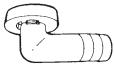 It is on the bottom of the packing case. It is on the bottom of the packing case. | 1 | ||
C Reducer assemblv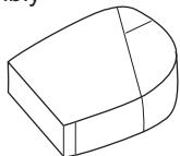 It is on the bottom of the packing case. It is on the bottom of the packing case. | 1 | ||||
E Refrigerant charge label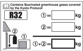 | 1 | D Screw bag(For fixing electrical wire anchor bands)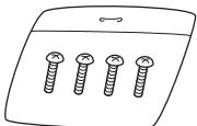 It is on the bottom of the packing case. It is on the bottom of the packing case. | 1 | ||
| F Multilingual fluorinated greenhouse gases labelIt is on the bottom of the packing case. | 1 | G Drain cap (1) | 6 | H Drain cap (2) | 3 |
Precautions for Selecting the Location
1) Choose a place solid enough to bear the weight and vibration of the unit, where the operation noise will not be amplified.
2) Choose a location where the hot air discharged from the unit or the operation noise will not cause a nuisance to the neighbours of the user.
3) Avoid places near a bedroom and the like, so that the operation noise will cause no trouble.
4) There must be sufficient spaces for carrying the unit into and out of the site.
5) There must be sufficient space for air passage and no obstructions around the air inlet and the air outlet.
6) The site must be free from the possibility of flammable gas leakage in a nearby place.
7) Install units, power cords and inter-unit wire at least 3m away from television and radio sets. This is to prevent interference to images and sounds. (Noises may be heard even if they are more than 3m away depending on radio wave conditions.)
8) In coastal areas or other places with salty atmosphere of sulfate gas, corrosion may shorten the life of the air conditioner.
9) Since water will flow from the drain of the outdoor unit, do not place under the unit anything which must be kept away from moisture.
NOTE
Cannot be installed hanging from ceiling or stacked.

CAUTION
When operating the air conditioner in a low outdoor ambient temperature, be sure to follow the instructions described below.
- To prevent exposure to wind, install the outdoor unit with its suction side facing the wall.
- Never install the outdoor unit at a site where the suction side may be exposed directly to wind.
- To prevent exposure to wind, it is recommended to install a baffle plate on the air discharge side of the outdoor unit.
- In heavy snowfall areas, select an installation site where the snow will not affect the unit.
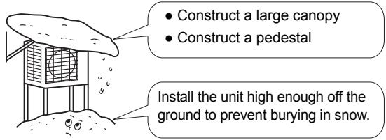
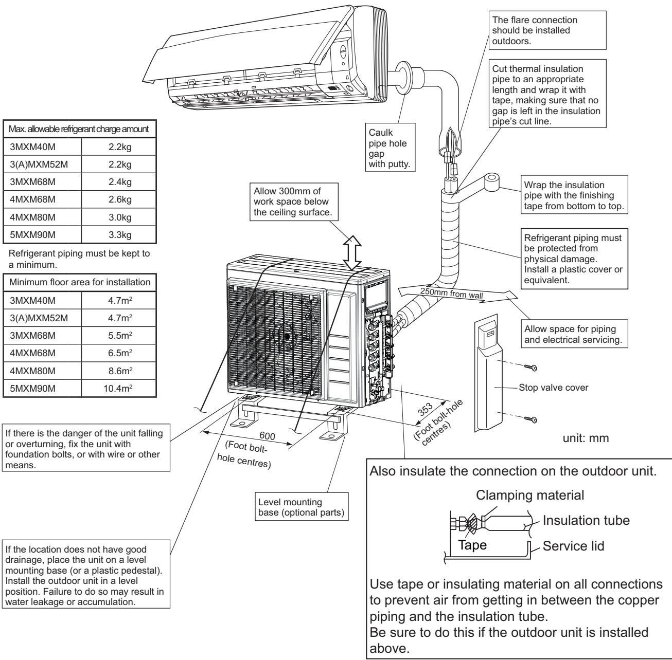
Indoor/Outdoor Unit Installation Drawings
For installation of the indoor units, refer to the installation manual which was provided with the units.
(The diagram shows a wall-mounted indoor unit.)

CAUTION
- Do not connect the embedded branch piping and the outdoor unit when only carrying out piping work without connecting the indoor unit in order to add another indoor unit later.
Make sure no dirt or moisture gets into either side of the embedded branch piping.
See "7 Refrigerant piping work" on page 9 for details. - It is impossible to connect the indoor unit for one room only. Be sure to connect at least 2 rooms.
Installation
• Install the unit horizontally.
- The unit may be installed directly on a concrete verandah or a solid place if drainage is good.
- If the vibration may possibly be transmitted to the building, use a vibration-proof rubber (field supply).
1. Connections (connection port)
Install the indoor unit according to the table below, which shows the relationship between the class of indoor unit and the corresponding port.
The total indoor unit class that can be connected to this unit:
Heat pump type:
3MXM40M* - Up to 7.0kW
4MXM68M* - Up to 11.0kW
3MXM52M* - Up to 9.0kW
4MXM80M* - Up to 14.0kW
3AMXM52M* - Up to 9.0kW
5MXM90M* - Up to 15.5kW
3MXM68M* - Up to 11.0kW
| Port | 3MXM40M* | 3MXM52M*3AMXM52M* |
| A | 15, 20, 25, 35 | 15, 20, 25, 35, 42 |
| B | # # # #15,20,25,35 | # # # # #15,20,25,35,42, 50 |
| C | # # # #15,20,25,35 | # # # # #15,20,25,35,42, 50 |
| Port | 3MXM68M* | 4MXM68M* |
| A | 15, 20, 25, 35, 42 | 15, 20, 25, 35, 42 |
| B | # # # # #15,20,25,35,42, 50, 60 | 15, 20, 25, 35, 42 |
| C | # # # # #15,20,25,35,42, 50, 60 | # # # # #15,20,25,35,42, 50, 60 |
| D | # # # # #15,20,25,35,42, 50, 60 | |
| Port | 4MXM80M* | 5MXM90M* |
| A | 15, 20, 25, 35, 42 | 15, 20, 25, 35, 42 |
| B | # # # # #15,20,25,35,42, 50, 60 | 15, 20, 25, 35, 42 |
| C | # # # # #15,20,25,35,42, 50, 60 | |
| D | △ △ △ △ △ □ □15,20,25,35,42,50,60,71 | |
| E | △ △ △ △ △ □ □15,20,25,35,42,50,60,71 |
○ : Use a reducer to connect pipes.
: Use No. 2 and 4 reducers.
: Use No. 5 and 6 reducers.
☐ : Use No. 1 and 3 reducers.
Refer to “How to Use Reducers” on page 10 for information on reducer numbers and their shapes.
Precautions on Installation
- Check the strength and level of the installation ground so that the unit will not cause any operating vibration or noise after installed.
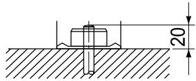
- In accordance with the foundation drawing in fix the unit securely by means of the foundation bolts. (Prepare 4 sets of M8 or M10 foundation bolts, nuts and washers each which are available on the market.)
- It is best to screw in the foundation bolts until their ends are 20mm from the foundation surface.
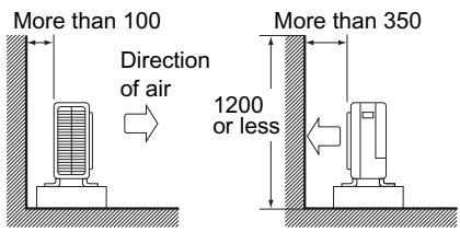
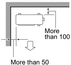
Outdoor Unit Installation Guideline
- Where a wall or other obstacle is in the path of outdoor unit's inlet or outlet airflow, follow the installation guidelines below.
- For any of the below installation patterns, the wall height on the exhaust side should be 1200mm or less.
Wall facing one side
Side view
Walls facing two sides
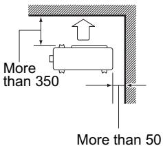
Top view
Walls facing three sides
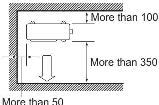
Top view
unit: mm
Selecting a Location for Installation of the Indoor Units
- The maximum allowable length of refrigerant piping, and the maximum allowable height difference between the outdoor and indoor units, are listed below. (The shorter the refrigerant piping, the better the performance. Connect so that the piping is as short as possible. Shortest allowable length per room is 3m.)
| Outdoor unit capacity class | 3MXM40M* | 3MXM52M*3AMXM52M* | 3MXM68M* | 4MXM68M* | 4MXM80M* | 5MXM90M* |
| Piping to each indoor unit | 25m max. | 25m max. | 25m max. | 25m max. | 25m max. | 25m max. |
| Total length of piping between all units | 50m max. | 50m max. | 50m max. | 60m max. | 70m max. | 75m max. |
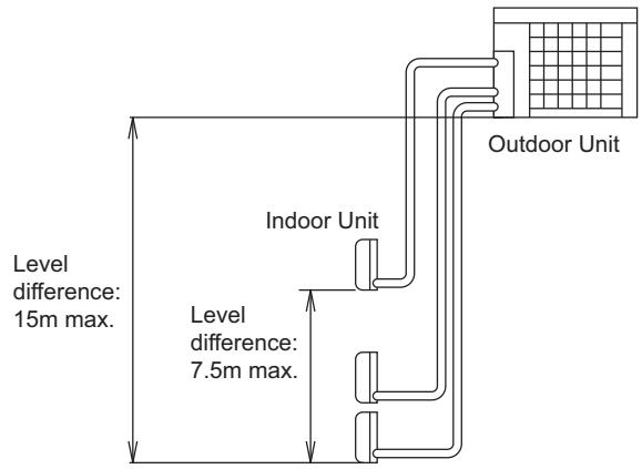
If the outdoor unit is positioned higher than the indoor units.
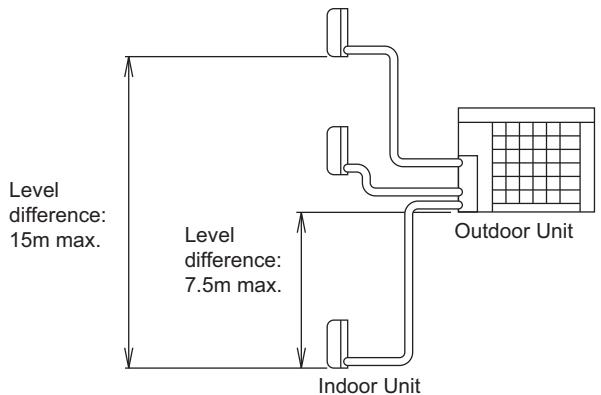
If the outdoor unit is positioned otherwise. (If lower than one or more indoor units)
Refrigerant Piping Work
1. Installing outdoor unit
1) When installing the outdoor unit, refer to "Precautions for Selecting the Location" on page 3 and the "Outdoor Unit Installation Drawings" on page 4.
2) If drain work is necessary, follow the procedures below.
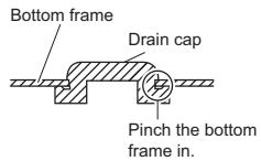
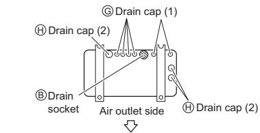
2. Drain work
- If the drain port is covered by a mounting base or floor surface, place additional foot bases of at least 1-1/4 inch (30mm) in height under the outdoor unit's feet.
- In cold areas, do not use a drain socket, drain caps (1,2) and a drain hose with the outdoor unit. (Otherwise, the drain water may freeze, impairing heating performance.)
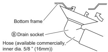
1) Attach Ⓖ drain cap (1) and Ⓗ drain cap (2).
2) Attach Ⓑ drain socket.
3. Refrigerant piping

CAUTION
- Use the flare nut fixed to the main unit. (To prevent cracking of the flare nut by aged deterioration.)
• To prevent gas leakage, apply refrigeration oil only to the inner surface of the flare. (Use refrigeration oil for R32.) - Use torque wrenches when tightening the flare nuts to prevent damage to the flare nuts and gas leakage.
- Do not reuse joints which have been used once already.
- Installation shall be done by an installer, the choice of materials and installation shall comply with the applicable legislation. In Europe the EN378 is the applicable standard that shall be used.
- Ensure that the field piping and connections are not subjected to stress.
Align the centres of both flares and tighten the flare nuts 3 or 4 turns by hand. Then tighten them fully with the torque wrenches.
![[Apply oil] Do not apply refrigeration oil to the outer surface. Flare nut Apply refrigeration oil to the inner surface of the flare. Do not apply refrigeration oil to the flare nut to avoid tightening with excessive torque.](/content/2020/11/206432/images/a763ccc4ccfdbfdcf741f73ab7b5fe39df00f91043edbebbcf157d3eedbb6d37.jpg)
![[Tighten] Torque wrench Spanner Piping union Flare nut](/content/2020/11/206432/images/046ab90144364b22f3e83c3b0e00306c253697d95e8a3355554b49ed8d7c5870.jpg)
| Flare nut tightening torque | |
| ø 1/4 inch (6.4mm) | 10-1/2 — 12-3/4ft ● lbf (14.2-17.2N ● m) |
| ø 3/8 inch (9.5mm) | 24-1/8 — 29-1/2ft ● lbf (32.7-39.9N ● m) |
| ø 1/2 inch (12.7mm) | 36-1/2 — 44-1/2ft ● lbf (49.5-60.3N ● m) |
| ø 5/8 inch (15.9mm) | 45-5/8 — 55-5/8ft ● lbf (61.8-75.4N ● m) |
| Width across flats | 11/16 inch (17mm) | 3/4 inch (19mm) | 7/8 inch (22mm) | 11/16 inch (27mm) |
| Valve cap tightening torque | 10-1/2 — 12-5/8ft ● lbf(14.2-17.2N ● m) | 12-5/8 — 15-3/8ft ● lbf(17.1-20.9N ● m) | 16 — 20-1/4ft ● lbf(21.6-27.4N ● m) | 35-3/8 — 44-1/8ft ● lbf(48-59.8N ● m) |
| Service port cap tightening torque | 8 — 10-7/8ft ● lbf(10.8-14.7N ● m) |
Refrigerant Piping Work
4. Evacuating the air with a vacuum pump and checking for gas leakage

WARNING
- Do not mix any substance other than the specified refrigerant (R32) into the refrigeration cycle.
- When refrigerant gas leaks should occur, ventilate the room as soon and as much as possible.
• R32, as well as other refrigerants, should always be recovered and never be released directly into the environment. - Use a vacuum pump for R32 or R410A exclusively. Using the same vacuum pump for different refrigerants may damage the vacuum pump or the unit.
- Use tools for R32 or R410A (such as the gauge manifold, charging hose, or vacuum pump adapter).
- During tests never pressurize the appliances with a pressure higher than the maximum allowable pressure (as indicated on the nameplate of the unit).
- If refrigerant gas leaks, ventilate the area immediately. Toxic gas may be produced if refrigerant gas comes into contact with fire.
-
Never directly touch any accidental leaking refrigerant. This could result in severe wounds caused by frostbite.
-
When piping work is completed, it is necessary to purge the air and check for gas leakage.
- If using additional refrigerant, perform air purging from the refrigerant pipes and indoor unit using a vacuum pump, then charge additional refrigerant.
- Use a hexagonal wrench (4mm) to operate the stop valve rod.
- All refrigerant pipe joints should be tightened with a torque wrench to the specified tightening torque.
1) Connect projection side of charging hose (which comes from gauge manifold) to gas stop valve's service port.
2) Fully open gauge manifold's low-pressure valve (Lo) and completely close its high-pressure valve (Hi). (High-pressure valve subsequently requires no operation.)
3) Perform vacuum pumping and make sure that the compound pressure gauge reads -0.1MPa (-76cmHg). Evacuation for at least 1 hour is recommended.
4) Close gauge manifold's low-pressure valve (Lo) and stop vacuum pump.
(Keep this state for 4-5 minutes to make sure that the compound pressure gauge pointer does not swing back. If it does go back, this may indicate the presence of moisture or leaking from connecting parts. After inspecting all the connection and loosening then retightening the nuts, repeat steps 2-4.)
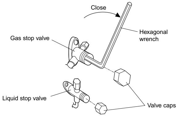
5) Remove covers from liquid stop valve and gas stop valve.
6) Turn the liquid stop valve's rod 90 degrees counterclockwise with a hexagonal wrench to open valve. Close it after 5 seconds, and check for gas leakage. Using soapy water, check for gas leakage from indoor unit's flare and outdoor unit's flare and valve rods. After the check is complete, wipe all soapy water off.
7) Disconnect charging hose from gas stop valve's service port, then fully open liquid and gas stop valves. (Do not attempt to turn valve rod beyond its stop.)
8) Tighten valve caps and service port caps for the liquid and gas stop valves with a torque wrench at the specified torques. See “3. Refrigerant piping” on page 7 for details.
Refrigerant Piping Work
5. Charging with refrigerant
1) If the total length of piping for all rooms exceeds the figure listed below, additionally charge with 20g of refrigerant (R32) for each additional meter of piping.
| Outdoor capacity class | 3MXM40M, 3MXM52M, 3AMXM52M, 3MXM68M, 4MXM68M, 4MXM80M, 5MXM90M |
| Total length of piping for all rooms | 30m |
Important information regarding the refrigerant used
This product contains fluorinated greenhouse gases covered by the Kyoto Protocol.
Do not vent gases into the atmosphere.
Refrigerant type: R32
GWP ^(1) value: 675 ^(1) GWP = global warming potential
Please fill in with indelible ink,
■① the factory refrigerant charge of the product,
■ ② the additional refrigerant amount charged in the field and
■①+② the total refrigerant charge
on the refrigerant charge label supplied with the product.
The filled out label must be adhered in the proximity of the product charging port (e.g. onto the inside of the stop valve cover).
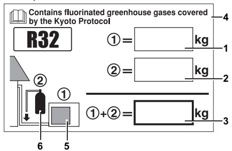
1 factory refrigerant charge of the product: see unit name plate
2 additional refrigerant amount charged in the field (Refer to the above information for the quantity of refrigerant replenishment.)
3 total refrigerant charge
4 Contains fluorinated greenhouse gases covered by the Kyoto Protocol
5 outdoor unit
6 refrigerant cylinder and manifold for charging
NOTE:
National implementation of EU regulation on certain fluorinated greenhouse gases may require to provide the appropriate official national language on the unit. Therefore an additional multilingual fluorinated greenhouse gases label is supplied with the unit. Sticking instructions are illustrated on the backside of that label.

CAUTION
Even though the stop valve is fully closed, the refrigerant may slowly leak out; do not leave the flare nut removed for a long period of time.
Refrigerant Piping Work
6. Refrigerant piping work
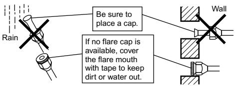
Cautions on pipe handling
1) Protect the open end of the pipe against dust and moisture.
2) All pipe bends should be as gentle as possible. Use a pipe bender for bending.
Selection of copper and heat insulation materials
When using commercial copper pipes and fittings, observe the following:
1) Insulation material: Polyethylene foam
Heat transfer rate: 0.041 to 0.052W/mK (0.035 to 0.045kcal/mh°C)
Refrigerant gas pipe's surface temperature reaches 110^ max.
Choose heat insulation materials that will withstand this temperature.
2) Be sure to insulate both the gas and liquid piping and to provide insulation dimensions as below.
| Gas pipe | O.D.: 9.5mm, 12.7mm / Thickness: 0.8mm (C1220T-O)O.D.: 15.9mm / Thickness: 1.0mm (C1220T-O) |
| Liquid pipe | O.D.: 6.4mm / Thickness: 0.8mm (C1220T-O) |
| Gas pipe insulation | I.D.: 12-15mm, I.D.: 16-20mm / Thickness: 13mm min. |
| Liquid pipe insulation | I.D.: 8-10mm / Thickness: 10mm min. |
| Minimum bend radius | O.D.: 6.4mm, 9.5mm / 30mm or moreO.D.: 12.7mm / 40mm or moreO.D.: 15.9mm / 50mm or more |
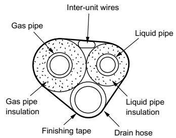
3) Use separate thermal insulation pipes for gas and liquid refrigerant pipes.
4) Piping and other pressure containing parts shall comply with the applicable legislation and shall be suitable for refrigerant. Use phosphoric acid deoxidised seamless copper for refrigerant.
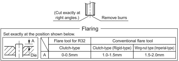
7. Flaring the pipe end
1) Cut the pipe end with a pipe cutter.
2) Remove burrs with the cut surface facing downward so that the chips do not enter the pipe.
3) Put the flare nut on the pipe.
4) Flare the pipe.
5) Check that the flaring is properly made.
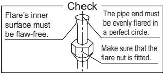
WARNING
- Do not use mineral oil on flared part.
- Prevent mineral oil from getting into the system as this would reduce the lifetime of the units.
- Never use piping which has been used for previous installations. Only use parts which are delivered with the unit.
- Never install a dryer to this R32 unit in order to guarantee its lifetime.
- The drying material may dissolve and damage the system.
- Incomplete flaring may cause refrigerant gas leakage.
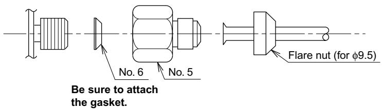
How to Use Reducers
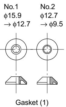
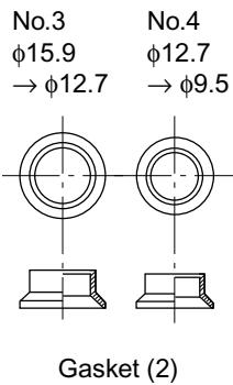
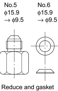
Use the reducers supplied with the unit as described below.
1) Connecting a pipe of 12.7 to a gas pipe connection port for 15.9:
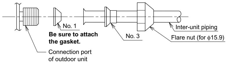
2) Connecting a pipe of 9.5 to a gas pipe connection port for 15.9 :
3) Connecting a pipe of 9.5 to a gas pipe connection port for 12.7 :
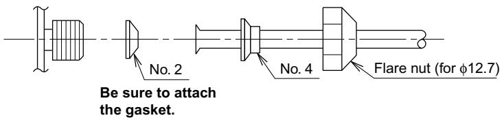
- When using the reducer packing shown above, be careful not to over-tighten the nut, or the smaller pipe may be damaged. (about 2/3 - 1 the normal torque)
- Apply a coat of refrigeration oil to the threaded connection port of the outdoor unit where the flare nut comes in.
- Use an appropriate wrench to avoid damaging the connection thread by overtightening the flare nut.
| Flare nut tightening torque | |
| Flare nut for φ9.5 | 32.7–39.9N·m(333–407kgf·cm) |
| Flare nut for φ12.7 | 49.5–60.3N·m(505–615kgf·cm) |
| Flare nut for φ15.9 | 61.8–75.4N·m(630–769kgf·cm) |
Pump Down Operation
In order to protect the environment, be sure to pump down when relocating or disposing of the unit.
1) Remove the valve cap from liquid stop valve and gas stop valve.
2) Carry out forced cooling operation.
3) After 5 to 10 minutes, close the liquid stop valve with a hexagonal wrench.
4) After 2 to 3 minutes, close the gas stop valve and stop forced cooling operation.
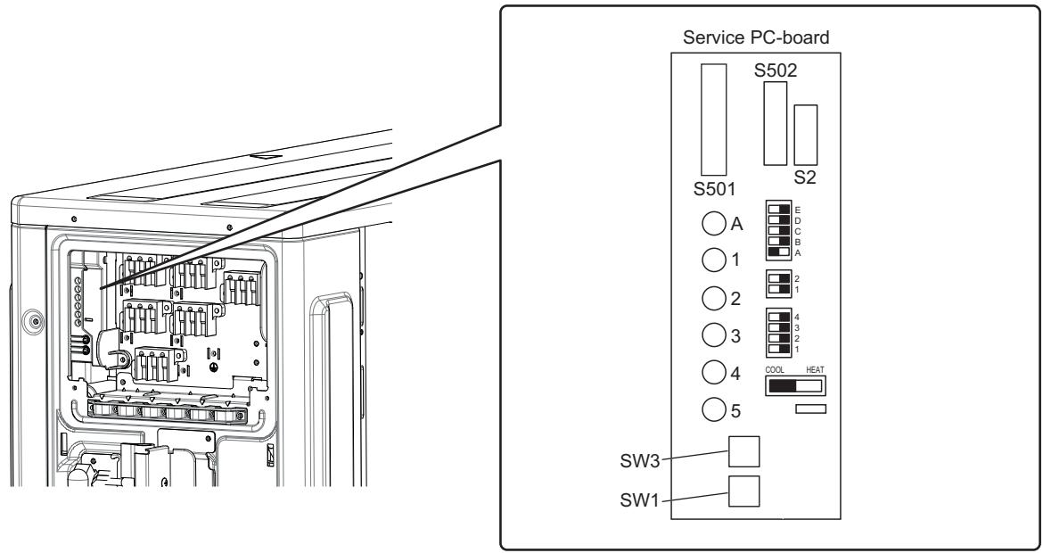
1. Forced operation
1) Switch off the power.
2) Remove the Service lid (2 screws).
3) Remove the service PC-board switch cover (1 screw).
4) Switch SW5 and SW6 to off.
5) Turn the operation mode switch (SW2) to COOL.
6) Screw the service PC-board switch cover back on (1 screw)-
7) Switch the power on.
8) Push the forced operation switch (SW1) above the service PC-board cover.
■Start forced colling operation.
To stop forced operation, push the forced operation switch (SW1) again.

WARNING
Do not remove the switch cover unless the power has been turned off. (Risk of electric shock)

WARNING
- Do not use tapped wires, stranded wires, extension cords, or starburst connections, as they may cause overheating, electrical shock, or fire.
- Do not use locally purchased electrical parts inside the product. (Do not branch the power for the drain pump, etc., from the terminal block.) Doing so may cause electric shock or fire.
- Be sure to install an earth leakage breaker. (One that can handle higher harmonics.)
(This unit uses an inverter, which means that an earth leakage breaker capable of handling harmonics must be used, in order to prevent malfunctioning of the earth leakage breaker itself.) - Use an all-pole disconnection type breaker with at least 3mm between the contact point gaps.
- Do not connect the power wire to the indoor unit. Doing so may cause electric shock or fire.
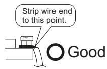
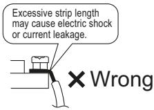
1) Strip the insulation from the wire (3/4inch (20mm)).
2) Connect the connection wires between the indoor and outdoor units so that the terminal numbers match. Tighten the terminal screws securely. We recommend a flathead screwdriver be used to tighten the screws.
3) Be sure to match the symbols for wiring and piping.
4) Pull the wire lightly to make sure that it does not disconnect.
5) Pass the wiring through the cutout on the bottom of the protection plate and attach the protection plate.
6) After completing the work, reattach the service lid to its original position.
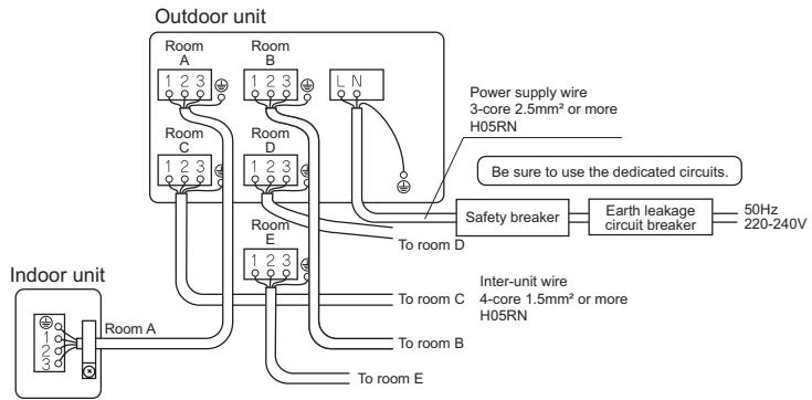
flowchart
graph TD
    A["Indoor unit"] --> B["Room A"]
    A --> C["Room B"]
    A --> D["Room C"]
    A --> E["Room D"]
    A --> F["Room E"]
    A --> G["Room A"]
    H["Outdoor unit"] --> I["Power supply wire 3-core 2.5mm² or more H05RN"]
    H --> J["Safety breaker"]
    H --> K["Earth leakage circuit breaker"]
    H --> L["Inter-unit wire 4-core 1.5mm² or more H05RN"]
    H --> M["Be sure to use the dedicated circuits."]
    N["Indoor unit"] --> O["To room D"]
    N --> P["To room C"]
    N --> Q["To room B"]
    N --> R["To room E"]

CAUTION
- Precautions to be taken for power supply wiring. When using stranded wires, make sure to use the round crimp-style terminal for connection to the power supply terminal
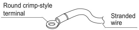
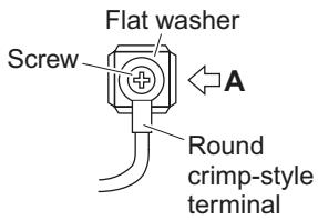
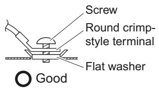
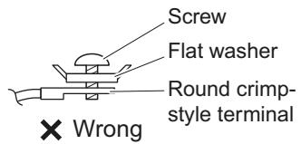
Arrow view A
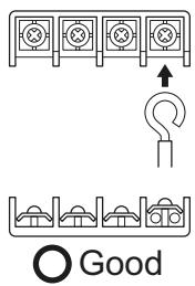
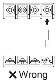
- When connecting the inter-unit wires to the terminal block using a single core wire, be sure to curl the end of the lead. Improper work may cause heat and fires.
Stripping wire at terminal block
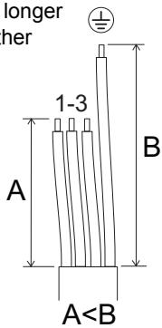
- Make sure that the earth wire between the pull relief and terminal is longer than the other wires.
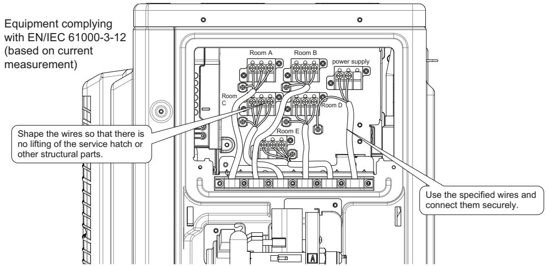
natural_image
Interior view of an electrical cabinet showing internal circuitry and wiring (no text or labels visible)CAUTION
- Before connecting or disconnecting the selective connector for standby electricity saving, make sure that the main power supply is turned off. - The selective connector for standby electricity saving is required if an indoor unit other than the above applicable one is connected.Priority Room Setting
\- To use priority room setting, initial settings must be made when the unit is installed. Explain the priority room setting, as described below, to the customer, and confirm whether or not the customer wants to use priority room setting. Setting it in the guest and living rooms is convenient.1. About the priority room setting function
The indoor unit for which priority room setting is applied takes priority in the following cases.1-1. Operation mode priority
The operation mode of the indoor unit which is set for priority room setting takes priority. If the set indoor unit is operating, all other indoor units do not operate and enter standby mode, according to the operation mode of the set indoor unit.1-2. Priority during high-power operation
If the indoor unit which is set for priority room setting is operating at high power, the capabilities of other indoor units will be somewhat reduced. Power supply gives priority to the indoor unit which is set for priority room setting.1-3. Quiet operation priority
Setting the indoor unit to quiet operation will make the outdoor unit run quietly.Setting procedure
Slide the switch to the ON side for the switch that corresponds to the piping connected to the indoor unit to be set. (In the figure below, it is room A.) Once the settings are complete, reset the power.Be sure to only set one room
Night Quiet Mode Setting
\- If Night Quiet Mode is to be used, initial settings must be made when the unit is installed. Explain Night Quiet Mode, as described below, to the customer, and confirm whether or not the customer wants to use Night Quiet Mode.About Night Quiet Mode
The Night Quiet Mode function reduces operating noise of the outdoor unit at nighttime. This function is useful if the customer is worried about the effects of the operating noise on the neighbors. However, if Night Quiet Mode is running, cooling capacity will be saved.Setting procedure
Turn the Night Quiet Mode switch (SW6-1) to on.HEAT Mode Lock
\- Use the HEAT Mode Lock switch (SW5-1) in the "ON" position.

COOL Mode Lock
\- Use the S15 connector to set the unit to cool only.
Setting to only cool (C) : short-circuit pins 3 and 5 of the connector Trial Operation and Testing
- Before starting the test run, measure the voltage at the primary side of the safety breaker. - Check that all liquid and gas stop valves are fully open. - Check that piping and wiring all match. The wiring error check can be conveniently used for underground wiring and other wiring that cannot be directly checked.1. Wiring error check
- This product is capable of automatic correction of wiring error. - Press the “wiring error check switch” on the outdoor unit service PC-board. However, the wiring error check switch will not function for 3 minutes after the safety breaker is turned on, or depending on the outside air conditions (See Note 2.). About 15–20 minutes after the switch is pressed, the errors in the connection wiring will be corrected. The service monitor LEDs indicate whether or not correction is possible, as shown in the table below. For details about how to read the LED display, refer to the service manual. If self-correction is not possible, check the indoor unit wiring and piping in the usual manner. | LED | 1 | 2 | 3 | 4 | 5 | Message |
| Status | All Flashing | Automatic correction impossible | ||||
| Flashing One after another | Automatic correction completed | |||||
| (One or more of LEDs 1 to 4 are ON) | Abnormal stop [NOTE. 4] | |||||
flowchart
graph TD
    A["Terminal block"] --> B["A"]
    A --> C["C"]
    B --> D["D"]
    C --> D
    D --> E["From Room A to the "bedroom""]
    D --> F["From Room B to the "living room""]
    D --> G["From Room C to the "kitchen""]
    H["Terminal block"] --> I["B"]
    H --> J["D"]
NOTE:
1) For two rooms, LED 3, 4 and 5 are not displayed, and for three rooms, LED 4 and 5 is not displayed, and for four rooms, LED 5 is not displayed. 2) If the outside air temperature is 5^ or less, the wiring error check function will not operate. 3) After wiring error check operation is completed, LED indication will continue until ordinary operation starts. This is normal. 4) Follow the product diagnosis procedures. (Details of product error diagnosis are listed on the back of the right side plate.)Trial Operation and Testing
2. Trial operation and testing
1) To test cooling, set for the lowest temperature. To test heating, set for the highest temperature. (Depending on the room temperature, only heating or cooling (but not both) may be possible.) 2) After the unit is stopped, it will not start again (heating or cooling) for approximately 3 minutes. 3) When trial operation is conducted in the HEAT operation directly after the circuit breaker is turned on, in some cases no air will be output for about 15 minutes in order to protect the air conditioner. 4) During the test run, first check the operation of each unit individually. Then also check the simultaneous operation of all indoor units. Check both heating and cooling operation. 5) After running the unit for approximately 20 minutes, measure the temperatures at the indoor unit inlet and outlet. If the measurements are above the values shown in the table below, then they are normal.| Cooling | Heating | |
| Temperature difference between inlet and outlet | Approx. 8°C | Approx. 20°C |
3. Items to check
| Check item | Consequences of trouble | Check |
| Are the indoor units installed securely? | Falling, vibration, noise | |
| Has an inspection been made to check for gas leakage? | Incomplete cooling/heating function | |
| Has complete thermal insulation been done (gas pipes, liquid pipes, indoor portions of the drain hose extension)? | Water leakage | |
| Is the drainage secure? | Water leakage | |
| Are the ground wire connections secure? | Electrical leakage | |
| Are the electric wires connected correctly? | Incomplete cooling/heating function | |
| Is the wiring in accordance with the specifications? | No operation or burn damage | |
| Are the inlets/outlets of the indoor and outdoor units free of any obstructions? | Incomplete cooling/heating function | |
| Are the stop valves open? | Incomplete cooling/heating function | |
| Do the marks match (room A, room B, room C, room D, room E) on the wiring and piping for each indoor unit? | Incomplete cooling/heating function | |
| Is the priority room setting set for 2 or more rooms? | The priority room setting will not func-tion. |
ATTENTION
- Have the customer actually operate the unit while looking at the manual included with the indoor unit. Instruct the customer how to operate the unit correctly (particularly cleaning of the air filters, operation procedures, and temperature adjustment). - Even when the air conditioner is not operating, it consumes some electric power. If the customer is not going to use the unit soon after it is installed, turn off the breaker to avoid wasting electricity. - If additional refrigerant has been charged because of long piping, list the amount added on the nameplate on the reverse side of the stop valve cover.Piping Diagram
Outdoor Unit flowchart
graph TD
    A["Refrigerant flow"] --> B["Refrnet header"]
    B --> C["Heat exchanger"]
    C --> D["Outdoor air temperature thermistor"]
    D --> E["Capillary tube"]
    E --> F["Distributor"]
    F --> G["Muffler with filter"]
    G --> H["Liquid stop valve"]
    H --> I["4-way valve"]
    I --> J["Automatic reset"]
    J --> K["Chamber"]
    K --> L["Compressor"]
    L --> M["Discharge pipe thermistor"]
    M --> N["Accumulator"]
    N --> O["Accumulator"]
    O --> P["High pressure switch Manual reset"]
    P --> Q["4-way valve"]
    Q --> R["Electric expansion valve"]
    R --> S["Thermistor (liquid)"]
    S --> T["Thermostat with filter"]
    T --> U["Room A (6.4CuT)"]
    T --> V["Room B (6.4CuT)"]
    T --> W["Room C (6.4CuT)"]
    X["Refrigerant flow"] --> Y["Cooling"]
    Z["Heating"] --> AA["Heating"]
    AB["Propeller fan"] --> AC["Fan motor"]
    AD["Refrigerant flow"] --> AE["Cooling"]
    AF["Heating"] --> AG["Heating"]
    AH["Applicable models"] --> AI["3MXM40M2V1B"]
    AH --> AJ["3MXM52M2V1B"]
    AH --> AK["3AMXM52M2V1B"]
flowchart
graph TD
    A["Refrigerant flow"] --> B["Refrnet header"]
    B --> C["Heat exchanger"]
    C --> D["Outdoor air temperature thermistor"]
    D --> E["Capillary tube"]
    E --> F["Distributor"]
    F --> G["Solenoid valve"]
    G --> H["4-way valve"]
    H --> I["Automatic reset"]
    I --> J["High pressure switch Manual reset"]
    J --> K["Compressor"]
    K --> L["Discharge pipe thermistor"]
    L --> M["Accumulator"]
    M --> N["Accumulator"]
    N --> O["4-way valve"]
    O --> P["Muffler with filter"]
    P --> Q["Liquid stop valve"]
    Q --> R["Reservoir"]
    R --> S["Thermistor (liquid)"]
    S --> T["Filter"]
    T --> U["Room A (6.4CuT)"]
    T --> V["Room B (6.4CuT)"]
    T --> W["Room C (6.4CuT)"]
    X["Field piping Liquid"] --> Y["Field piping Gas"]
    Z["Applicable models 3MXM68M2V1B"] --> AA["Refrnet header"]
    AB["Field piping Liquid"] --> AC["MuA"]
    AB --> AD["MuB"]
    AB --> AE["MuC"]
    AF["Refrigerant flow"] --> AG["Cooling"]
    AH["Heating"] --> AI["Refrigerant flow"]
NOTE:
When the high pressure switch is activated it must be reset manually by a qualified person.Piping Diagram
Outdoor Unit flowchart
graph TD
    A["Refrigerant flow"] --> B["Refrigerant fan"]
    B --> C["Capillary tube"]
    C --> D["4-way valve"]
    D --> E["Automatic reset"]
    E --> F["High pressure switch Manual reset"]
    F --> G["Compressor"]
    G --> H["Accumulator"]
    H --> I["Accumulator"]
    I --> J["Gas stop valve"]
    J --> K["Thermistor (gas)"]
    K --> L["Field piping Gas"]
    L --> M["Room A (9.5CuT)"]
    L --> N["Room B (9.5CuT)"]
    L --> O["Room C (12.7CuT)"]
    L --> P["Room D (12.7CuT)"]
    Q["Outdoor air temperature thermistor"] --> R["Heat exchanger"]
    R --> S["Refnet header"]
    S --> T["Distributor"]
    T --> U["Solenoid valve"]
    U --> V["Sv"]
    V --> W["12.7CuT"]
    W --> X["12.7CuT"]
    X --> Y["15.9CuT"]
    Y --> Z["12.7CuT"]
    Z --> AA["4-way valve"]
    AA --> AB["Electric expansion valve"]
    AB --> AC["Thermistor (liquid)"]
    AC --> AD["Filter"]
    AD --> AE["Room A (6.4CuT)"]
    AD --> AF["Room B (6.4CuT)"]
    AD --> AG["Room C (6.4CuT)"]
    AD --> AH["Room D (6.4CuT)"]
    AI["Refrigerant flow"] --> AJ["Cooling"]
    AJ --> AK["Heating"]
    AL["Applicable models 4MXM68M2V1B"] --> AM["Field piping Liquid"]
flowchart
graph TD
    A["Outdoor air temperature thermistor"] --> B["Heat exchanger"]
    B --> C["Capillary tube"]
    C --> D["Liquid receiver"]
    D --> E["Solenoid valve"]
    E --> F["Muffler with filter"]
    F --> G["Liquid stop valve"]
    G --> H["4-way valve"]
    H --> I["Propeller fan"]
    I --> J["Fan motor"]
    J --> K["4-way valve"]
    K --> L["Automatic reset"]
    L --> M["High pressure switch Manual reset"]
    M --> N["Compressor"]
    N --> O["Discharge pipe thermistor"]
    O --> P["Refrigerant flow → Cooling → Heating"]

    subgraph Electronic expansion valve
        Q["Thermistor (liquid) Filter"] --> R["H Room A (6.4CuT)"]
        S["MuS"] --> T["H Room B (6.4CuT)"]
        U["Mn"] --> V["H Room C (6.4CuT)"]
        W["MnS"] --> X["H Room D (6.4CuT)"]
    end

    subgraph Field piping Liquid
        Y["Field piping Gas"] --> Z["Room A (9.5CuT)"]
        AA["Room B (12.7CuT)"] --> AB["Room C (15.9CuT)"]
        AC["Room D (15.9CuT)"] --> AD["Field piping Liquid"]
NOTE:
When the high pressure switch is activated it must be reset manually by a qualified person.Piping Diagram
Outdoor Unit flowchart
graph TD
    A["Refrigerant flow"] --> B["Refrigerant fan"]
    B --> C["Fan motor"]
    C --> D["4-way valve"]
    D --> E["Automatic reset"]
    E --> F["Compressor"]
    F --> G["Accumulator"]
    G --> H["High pressure switch Manual reset"]
    H --> I["Muffler"]
    I --> J["Reservoir"]
    J --> K["Heat exchanger"]
    K --> L["Outdoor air temperature thermistor"]
    L --> M["Heat exchanger"]
    M --> N["Refnet header"]
    N --> O["Refrigerant flow"]

    subgraph Electronic expansion valve
        P1["Thermistor (liquid)"]
        P2["Filter"]
        P3["Room A (6.4CuT)"]
        P4["Room B (6.4CuT)"]
        P5["Room C (6.4CuT)"]
        P6["Room D (6.4CuT)"]
        P7["Room E (6.4CuT)"]
    end

    subgraph Field piping
        Q1["Field piping Gas"]
        Q2["Field piping"]
    end

    L --> R["9.5CuT"]
    L --> S["9.5CuT"]
    L --> T["9.5CuT"]
    L --> U["9.5CuT"]
    L --> V["9.5CuT"]
    L --> W["9.5CuT"]

    X["Electric expansion tube"] --> Y["Distributor"]
    Y --> Z["Liquid receiver"]
    Z --> AA["Sv"]
    AA --> AB["Solenoid valve"]
    AB --> AC["4-way valve"]
    AC --> AD["Accumulator"]
    AD --> AE["Muffler with filter"]
    AE --> AF["Liquid stop valve"]

    AG["Refrigerant flow"] --> AH["Cooling"]
    AH --> AI["Heating"]

    subgraph Applicable models
        AJ["Applicable models 5MXM90M2V1B"]
    end