
FVXM-F/FVXS-F - Multi-split air conditioner DAIKIN - Free user manual and instructions
Find the device manual for free FVXM-F/FVXS-F DAIKIN in PDF.
User questions about FVXM-F/FVXS-F DAIKIN
0 question about this device. Answer the ones you know or ask your own.
Ask a new question about this device
Download the instructions for your Multi-split air conditioner in PDF format for free! Find your manual FVXM-F/FVXS-F - DAIKIN and take your electronic device back in hand. On this page are published all the documents necessary for the use of your device. FVXM-F/FVXS-F by DAIKIN.
USER MANUAL FVXM-F/FVXS-F DAIKIN
natural_image
Front view of a white industrial air conditioner unit with a circular vent and grid pattern (no visible text or symbols)
natural_image
Front view of a white industrial air conditioning unit with a circular fan grille (no visible text or symbols)[Applied Models]
● Inverter Multi : Cooling Only
● Inverter Multi : Heat Pump
SUPER MULTI NX
E-Series
F-Series
G-Series
K-Series
●Cooling Only
Outdoor Unit
3MKS50E3V1B 4MKS58E3V1B 4MKS75F2V1B 5MKS90E2V3B
Indoor Unit
FTXS25J2V1B FFQ25B9V1B FHQ35BWV1B FDBQ25B8V1
FTXS35J2V1B FFQ35B9V1B FHQ50BWV1B FBQ35C8VEB
FTXS42J2V1B FFQ50B9V1B FHQ60BWV1B FBQ50C8VEB
FTXS50J2V1B FFQ60B9V1B FBQ60C8VEB
FTXS60GV1B
FTXS71GV1B
●Heat Pump
Outdoor Unit
3MXS40K2V1B 3MXS68G2V1B 4MXS80E2V3B
3MXS52E3V1B 4MXS68F2V1B 5MXS90E2V3B
Indoor Unit
FTXG25JV1BW FVXG25K2V1B FCQG35FVEB
FTXG25JV1BA FVXG35K2V1B FCQG50FVEB
FTXG35JV1BW FVXG50K2V1B FCQG60FVEB
FTXG35JV1BA FVXS25FV1B FFQ25B9V1B
FTXG50JV1BW FVXS35FV1B FFQ35B9V1B
FTXG50JV1BA FVXS50FV1B FFQ50B9V1B
CTXS15K2V1B FLXS25BAVMB FFQ60B9V1B
FTXS20K2V1B FLXS35BAVMB FHQ35BWV1B
FTXS25K2V1B FLXS50BAVMB FHQ50BWV1B
CTXS35K2V1B FLXS60BAVMB FHQ60BWV1B
FTXS25J2V1B FDXS25E7VMB FDBQ25B8V1
FTXS35J2V1B FDXS35E7VMB FBQ35C8VEB
FTXS42J2V1B FDXS50C7VMB FBQ50C8VEB
FTXS50J2V1B FDXS60C7VMB FBQ60C8VEB
FTXS60GV1B
FTXS71GV1B
- Introduction ...... vii
1.1 Safety Cautions ...... vii
1.2 Used Icons xi
Part 1 List of Functions .... 1
- Cooling Only....2
1.1 Outdoor Unit....2
1.2 Indoor Unit....3
- Heat Pump 6
2.1 Outdoor Unit....6
2.2 Indoor Unit....7
Part 2 Specifications ....14
- Cooling Only....15
1.1 Outdoor Unit....15
1.2 Indoor Unit....17
- Heat Pump 22
2.1 Outdoor Unit....22
2.2 Indoor Unit....25
Part 3 Printed Circuit Board Connector Wiring Diagram ...... 37
- Outdoor Unit....38
- Indoor Unit....41
2.1 FTXG25/35/50JV1BW(A) 41
2.2 FTXS20/25K2V1B, CTXS15/35K2V1B 44
2.3 FTXS25/35/42/50J2V1B....46
2.4 FTXS60/71GV1B 49
2.5 FVXG25/35/50K2V1B 52
2.6 FVXS25/35/50FV1B 55
2.7 FLXS25/35/50/60BAVMB....57
2.8 FDXS25/35E7VMB, FDXS50/60C7VMB....59
2.9 FCQG35/50/60FVEB....61
2.10 FFQ25/35/50/60B9V1B 64
2.11 FHQ35/50/60BWV1B 66
2.12 FDBQ25B8V1....68
2.13 FBQ35/50/60C8VEB 70
- Wired Remote Controller....73
3.1 BRC1D528 73
3.2 BRC1E52A7, BRC1E52B7....74
Part 4 Function and Control....75
- Indoor Unit Control (RA Models)....76
1.1 Temperature Control 76
1.2 Frequency Principle....76
1.3 Operation Starting Control....78
1.4 Airflow Direction Control....79
1.5 Fan Speed Control for Indoor Unit 82
1.6 RADIANT Operation....83
1.7 Program Dry Operation 85
1.8 Automatic Operation....86
1.9 Thermostat Control....87
1.10 NIGHT SET Mode 89
1.11 ECONO Operation 90
1.12 HOME LEAVE Operation 91
1.13 INTELLIGENT EYE Operation 92
1.14 2-Area INTELLIGENT EYE Operation ....93
1.15 Inverter POWERFUL Operation....95
1.16 Multi-Colored Indicator Lamp / TIMER Lamp 95
1.17 Other Functions....97
- Indoor Unit Control (SA Models) 99
2.1 Drain Pump Control....99
2.2 Thermostat Sensor in Remote Controller....101
2.3 Freeze Prevention Control 103
2.4 Hot Start Control (In Heating Operation Only)....104
-
Function of Thermistor ....105
-
Control Specification ....107
4.1 Mode Hierarchy....107
4.2 Frequency Control....108
4.3 Controls at Mode Changing / Start-up....111
4.4 Discharge Pipe Temperature Control....112
4.5 Input Current Control....113
4.6 Freeze-up Protection Control 113
4.7 Heating Peak-cut Control 114
4.8 Outdoor Fan Control....115
4.9 Liquid Compression Protection Function....115
4.10 Defrost Control 116
4.11 Low Hz High Pressure Limit....117
4.12 Outdoor Electronic Expansion Valve Control 117
4.13 Malfunctions 122
Part 5 Operation Manual....124
- System Configuration....125
- RA Indoor Unit....126
2.1 FTXG, FTXS-K, CTXS, FVXG Series - ARC466A1, A2, A6 ......126
2.2 FTXS-J, FTXS-G, FVXS Series - ARC452A1, A3....178
2.3 FLXS, FDXS Series - ARC433B67, B69 218
- SA Indoor Unit....233
3.1 BRC1D528 233
Part 6 Service Diagnosis....248
- Troubleshooting with LED....250
1.1 Indoor Unit....250
1.2 Outdoor Unit 252
-
Problem Symptoms and Measures....253
-
Service Check Function 254
3.1 RA Indoor Unit - FTXG, FTXS, CTXS, FVXG, FVXS, FLXS, FDXS Series....254
3.2 SA Indoor Unit - FCQG, FFQ, FHQ, FDBQ, FBQ Series 263
- Code Indication on Remote Controller 267
4.1 RA Indoor Unit - FTXG, FTXS, CTXS, FVXG, FVXS, FLXS, FDXS Series....267
4.2 SA Indoor Unit - FCQG, FFQ, FHQ, FDBQ, FBQ Series 267
4.3 Sub Codes for SA Indoor Unit 268
4.4 Outdoor Unit 269
5. Troubleshooting for RA Indoor Unit - FTXG, FTXS, CTXS, FVXG, FVXS, FLXS, FDXS Series 270
5.1 Indoor Unit PCB Abnormality 270
5.2 Freeze-up Protection Control or Heating Peak-cut Control....272
5.3 Fan Motor or Related Abnormality .....274
5.4 Radiant Panel Temperature Rise, Indoor Electronic Expansion Valve (Motor Operated Valve) Abnormality, Freeze-up Protection Control (FVXG Series Only)....278
5.5 Thermistor or Related Abnormality (RA Indoor Unit)....280
5.6 Front Panel Open / Close Fault (FTXG Series Only) 281
5.7 Signal Transmission Error (between Indoor Unit and Outdoor Unit) ....282
5.8 Unspecified Voltage (between Indoor Unit and Outdoor Unit) .....283
6. Troubleshooting for SA Indoor Unit - FCQG, FFQ, FHQ, FDBQ, FBQ Series....284
6.1 Indoor Unit PCB Abnormality 284
6.2 Drain Water Level System Abnormality....285
6.3 Fan Motor or Related Abnormality 287
6.4 Swing Motor Lock (FHQ Series Only) 289
6.5 Drain System Abnormality....290
6.6 Thermistor or Related Abnormality (SA Indoor Unit)....291
6.7 Remote Controller Thermistor Abnormality 292
6.8 Signal Transmission Error
(between Indoor Unit and Remote Controller)....293
6.9 Signal Transmission Error
(between MAIN Remote Controller and SUB Remote Controller)......294
6.10 Field Setting Abnormality ....295
7. Troubleshooting for Outdoor Unit....296
7.1 Refrigerant Shortage 296
7.2 Low-voltage Detection or Over-voltage Detection.....298
7.3 Signal Transmission Error (on Outdoor Unit PCB)....300
7.4 Unspecified Voltage (between Indoor Unit and Outdoor Unit) / Anti-icing Function in Other Rooms....301
7.5 Anti-icing Function....302
7.6 Outdoor Unit PCB Abnormality....304
7.7 OL Activation (Compressor Overload) 305
7.8 Compressor Lock 306
7.9 DC Fan Lock 307
7.10 Input Overcurrent Detection 308
7.11 Discharge Pipe Temperature Control....309
7.12 High Pressure Control in Cooling 310
7.13 Compressor Sensor System Abnormality ....311
7.14 Position Sensor Abnormality ....313
7.15 CT or Related Abnormality 315
7.16 Thermistor or Related Abnormality (Outdoor Unit)....317
7.17 Electrical Box Temperature Rise....319
7.18 Radiation Fin Temperature Rise 321
7.19 Output Overcurrent Detection 323
8. Check....325
8.1 Thermistor Resistance Check 325
8.2 Fan Motor Connector Check 326
8.3 Hall IC Check 327
8.4 Indoor Electronic Expansion Valve Coil Check 327
8.5 Power Supply Waveform Check....328
8.6 Outdoor Electronic Expansion Valve Check....329
8.7 Four Way Valve Performance Check....330
8.8 Inverter Unit Refrigerant System Check....330
8.9 "Inverter Checker" Check 331
8.10 Rotation Pulse Check on the Outdoor Unit PCB 332
8.11 Installation Condition Check....333
8.12 Discharge Pressure Check....333
8.13 Outdoor Fan System Check....334
8.14 Capacitor Voltage Check....334
8.15 Power Module Check 335
Part 7 Removal Procedure....336
1. Outdoor Unit: 40-75 Class....337
1.1 Removal of Outer Panels 337
1.2 Removal of Electrical Box 341
1.3 Removal of PCBs....349
1.4 Removal of Outdoor Fan / Fan Motor....354
1.5 Removal of Sound Blankets....356
1.6 Removal of Coils / Thermistors 360
1.7 Removal of Distributor 363
1.8 Removal of Four Way Valve....364
1.9 Removal of Compressor....365
2. Outdoor Unit: 80/90 Class....367
2.1 Removal of Outer Panels 367
2.2 Removal of Electrical Box 382
2.3 Removal of PCBs....388
2.4 Removal of Fan Motor....392
2.5 Removal of Coils / Thermistors 393
2.6 Removal of Sound Blankets....399
2.7 Removal of Compressor....402
Part 8 Trial Operation and Field Settings....403
-
Pump Down Operation....404
-
Forced Operation 405
-
Wiring Error Check Function 406
-
Trial Operation ....408
4.1 RA Indoor Unit - FTXG, FTXS, CTXS, FVXG, FVXS, FLXS, FDXS Series....408
4.2 SA Indoor Unit - FCQG, FFQ, FHQ, FDBQ, FBQ Series 410
- Field Settings ....412
5.1 Outdoor Unit 412
5.2 RA Indoor Unit - FTXG, FTXS, CTXS, FVXG, FVXS, FLXS, FDXS Series....415
5.3 SA Indoor Unit - FCQG, FFQ, FHQ, FDBQ, FBQ Series 419
- Application of Silicon Grease to a Power Transistor and a Diode Bridge 423
Part 9 Appendix....424
- Piping Diagrams......425
1.1 Outdoor Unit 425
1.2 Indoor Unit....430
- Wiring Diagrams......437
2.1 Outdoor Unit 437
2.2 Indoor Unit 442
1. Introduction
1.1 Safety Cautions
Cautions and Warnings
■ Be sure to read the following safety cautions before conducting repair work.
■ The caution items are classified into “⚠ Warning” and “⚠ Caution”. The “⚠ Warning” items are especially important since they can lead to death or serious injury if they are not followed closely. The “⚠ Caution” items can also lead to serious accidents under some conditions if they are not followed. Therefore, be sure to observe all the safety caution items described below.
■ About the pictograms
This symbol indicates the item for which caution must be exercised.
The pictogram shows the item to which attention must be paid.
○ This symbol indicates the prohibited action.
The prohibited item or action is shown in the illustration or near the symbol.
● This symbol indicates the action that must be taken, or the instruction.
The instruction is shown in the illustration or near the symbol.
■ After the repair work is complete, be sure to conduct a test operation to ensure that the equipment operates normally, and explain the cautions for operating the product to the customer.
1.1.1 Cautions Regarding Safety of Workers
 Warning Warning | |
| Be sure to disconnect the power cable plug from the plug socket before disassembling the equipment for repair.Working on the equipment that is connected to the power supply may cause an electrical shock.If it is necessary to supply power to the equipment to conduct the repair or inspecting the circuits, do not touch any electrically charged sections of the equipment. | 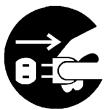 |
| If the refrigerant gas is discharged during the repair work, do not touch the discharged refrigerant gas.The refrigerant gas may cause frostbite. |  |
| When disconnecting the suction or discharge pipe of the compressor at the welded section, evacuate the refrigerant gas completely at a well-ventilated place first.If there is gas remaining inside the compressor, the refrigerant gas or refrigerating machine oil discharges when the pipe is disconnected, and it may cause injury. |  |
| If the refrigerant gas leaks during the repair work, ventilate the area. The refrigerant gas may generate toxic gases when it contacts flames. |  |
| The step-up capacitor supplies high-voltage electricity to the electrical components of the outdoor unit.Be sure to discharge the capacitor completely before conducting repair work.A charged capacitor may cause an electrical shock. | 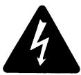 |
| Do not start or stop the air conditioner operation by plugging or unplugging the power cable plug.Plugging or unplugging the power cable plug to operate the equipment may cause an electrical shock or fire. |  |
| Be sure to wear a safety helmet, gloves, and a safety belt when working at a high place (more than 2 m). Insufficient safety measures may cause a fall accident. |  |
| In case of R-410A refrigerant models, be sure to use pipes, flare nuts and tools for the exclusive use of the R-410A refrigerant.The use of materials for R-22 refrigerant models may cause a serious accident such as a damage of refrigerant cycle as well as an equipment failure. | |
| Caution | |
| Do not repair the electrical components with wet hands. Working on the equipment with wet hands may cause an electrical shock. |  |
| Do not clean the air conditioner by splashing water. Washing the unit with water may cause an electrical shock. |  |
| Be sure to provide the grounding when repairing the equipment in a humid or wet place, to avoid electrical shocks. |  |
| Be sure to turn off the power switch and unplug the power cable when cleaning the equipment. The internal fan rotates at a high speed, and may cause injury. |  |
| Be sure to conduct repair work with appropriate tools. The use of inappropriate tools may cause injury. |  |
| Be sure to check that the refrigerating cycle section has cooled down enough before conducting repair work. Working on the unit when the refrigerating cycle section is hot may cause burns. |  |
| Use the welder in a well-ventilated place. Using the welder in an enclosed room may cause oxygen deficiency. |  |
1.1.2 Cautions Regarding Safety of Users
 Warning Warning | |
| Be sure to use parts listed in the service parts list of the applicable model and appropriate tools to conduct repair work. Never attempt to modify the equipment.The use of inappropriate parts or tools may cause an electrical shock, excessive heat generation or fire. |  |
| If the power cable and lead wires have scratches or deteriorated, be sure to replace them.Damaged cable and wires may cause an electrical shock, excessive heat generation or fire. |  |
| Do not use a joined power cable or extension cable, or share the same power outlet with other electrical appliances, since it may cause an electrical shock, excessive heat generation or fire. |  |
| Be sure to use an exclusive power circuit for the equipment, and follow the local technical standards related to the electrical equipment, the internal wiring regulations, and the instruction manual for installation when conducting electrical work.Insufficient power circuit capacity and improper electrical work may cause an electrical shock or fire. | |
| Be sure to use the specified cable for wiring between the indoor and outdoor units. Make the connections securely and route the cable properly so that there is no force pulling the cable at the connection terminals.Improper connections may cause excessive heat generation or fire. |  |
| When wiring between the indoor and outdoor units, make sure that the terminal cover does not lift off or dismount because of the cable.If the cover is not mounted properly, the terminal connection section may cause an electrical shock, excessive heat generation or fire. | |
| Do not damage or modify the power cable.Damaged or modified power cable may cause an electrical shock or fire.Placing heavy items on the power cable, and heating or pulling the power cable may damage the cable. |  |
| Do not mix air or gas other than the specified refrigerant (R-410A / R-22) in the refrigerant system.If air enters the refrigerating system, an excessively high pressure results, causing equipment damage and injury. | |
| If the refrigerant gas leaks, be sure to locate the leaking point and repair it before charging the refrigerant. After charging refrigerant, make sure that there is no refrigerant leak.If the leaking point cannot be located and the repair work must be stopped, be sure to perform pump-down and close the service valve, to prevent the refrigerant gas from leaking into the room. The refrigerant gas itself is harmless, but it may generate toxic gases when it contacts flames, such as fan and other heaters, stoves and ranges. |  |
| When relocating the equipment, make sure that the new installation site has sufficient strength to withstand the weight of the equipment.If the installation site does not have sufficient strength and if the installation work is not conducted securely, the equipment may fall and cause injury. | |
| Check to make sure that the power cable plug is not dirty or loose, then insert the plug into a power outlet securely.If the plug has dust or loose connection, it may cause an electrical shock or fire. |  |
| Be sure to install the product correctly by using the provided standard installation frame.Incorrect use of the installation frame and improper installation may cause the equipment to fall, resulting in injury. | For unitary type only |
| Be sure to install the product securely in the installation frame mounted on the window frame.If the unit is not securely mounted, it may fall and cause injury. | For unitary type only |
| When replacing the coin battery in the remote controller, be sure to dispose of the old battery to prevent children from swallowing it.If a child swallows the coin battery, see a doctor immediately. | |
| Caution | |
| Installation of a leakage breaker is necessary in some cases depending on the conditions of the installation site, to prevent electrical shocks. |  |
| Do not install the equipment in a place where there is a possibility of combustible gas leaks.If the combustible gas leaks and remains around the unit, it may cause a fire. |  |
| Check to see if the parts and wires are mounted and connected properly, and if the connections at the soldered or crimped terminals are secure.Improper installation and connections may cause excessive heat generation, fire or an electrical shock. | |
| If the installation platform or frame has corroded, replace it.Corroded installation platform or frame may cause the unit to fall, resulting in injury. | |
| Check the grounding, and repair it if the equipment is not properly grounded.Improper grounding may cause an electrical shock. |  |
| Be sure to measure the insulation resistance after the repair, and make sure that the resistance is 1 MΩ or higher.Faulty insulation may cause an electrical shock. | |
| Be sure to check the drainage of the indoor unit after the repair.Faulty drainage may cause the water to enter the room and wet the furniture and floor. |  |
| Do not tilt the unit when removing it.The water inside the unit may spill and wet the furniture and floor. |  |
| Be sure to install the packing and seal on the installation frame properly.If the packing and seal are not installed properly, water may enter the room and wet the furniture and floor. | For unitary type only |
1.2 Used Icons
Icons are used to attract the attention of the reader to specific information. The meaning of each icon is described in the table below:
| Icon | Type of Information | Description |
 Note: Note: | Note | A “note” provides information that is not indispensable, but may nevertheless be valuable to the reader, such as tips and tricks. |
 Caution Caution | Caution | A “caution” is used when there is danger that the reader, through incorrect manipulation, may damage equipment, loose data, get an unexpected result or has to restart (part of) a procedure. |
| Warning | Warning | A “warning” is used when there is danger of personal injury. |
 | Reference | A “reference” guides the reader to other places in this binder or in this manual, where he/she will find additional information on a specific topic. |
Part 1
List of Functions
- Cooling Only....2
1.1 Outdoor Unit 2
1.2 Indoor Unit....3
- Heat Pump 6
2.1 Outdoor Unit....6
2.2 Indoor Unit....7
1. Cooling Only
1.1 Outdoor Unit
| Category | Functions | 3MKS50E3V1B, 4MKS58E3V1B4MKS75F2V1B | 5MKS90E2V3B | Category | Functions | 3MKS50E3V1B, 4MKS58E3V1B4MKS75F2V1B | 5MKS90E2V3B |
| Basic Function | Inverter (with Inverter Power Control) | ● | ● | Health & Clean | Air-Purifying Filter | — | — |
| Operation Limit for Cooling (°CDB) | -10~46 | 10~46 | Photocatalytic Deodorizing Filter | — | — | ||
| Operation Limit for Heating (°CWB) | — | — | Air-Purifying Filter with Photocatalytic Deodorizing Function | — | — | ||
| PAM Control | ● | ● | |||||
| Standby Electricity Saving | — | — | Titanium Apatite Photocatalytic Air-Purifying Filter | — | — | ||
| Compressor | Oval Scroll Compressor | — | — | ||||
| Swing Compressor | ● | ● | Air Filter (Prefilter) | — | — | ||
| Rotary Compressor | — | — | Wipe-Clean Flat Panel | — | — | ||
| Reluctance DC Motor | ● | ● | Washable Grille | — | — | ||
| Comfortable Airflow | Power-Airflow Flap | — | — | MOLD PROOF Operation | — | — | |
| Power-Airflow Dual Flaps | — | — | Good-Sleep Cooling Operation | — | — | ||
| Power-Airflow Diffuser | — | — | Timer | WEEKLY TIMER Operation | — | — | |
| Wide-Angle Louvers | — | — | 24-Hour ON/OFF TIMER | — | — | ||
| Vertical Auto-Swing (Up and Down) | — | — | NIGHT SET Mode | — | — | ||
| Horizontal Auto-Swing (Right and Left) | — | — | Worry Free “Reliability & Durability” | Auto-Restart (after Power Failure) | — | — | |
| 3-D Airflow | — | — | Self-Diagnosis (Digital, LED) Display | ● | ● | ||
| COMFORT AIRFLOW Operation | — | — | Wiring Error Check Function | ● | ● | ||
| Comfort Control | Auto Fan Speed | — | — | Anti-Corrosion Treatment of Outdoor Heat Exchanger | ● | ● | |
| Indoor Unit Quiet Operation | — | — | Flexibility | Multi-Split / Split Type Compatible Indoor Unit | — | — | |
| NIGHT QUIET Mode (Automatic) | ● | ● | H/P, C/O Compatible Indoor Unit | — | — | ||
| OUTDOOR UNIT QUIET Operation (Manual) | ● | ● | Flexible Power Supply Correspondence | — | — | ||
| 2-Area INTELLIGENT EYE Operation | — | — | High Ceiling Application | — | — | ||
| INTELLIGENT EYE Operation | — | — | Chargeless | ● | 65 m | ||
| Quick Warming Function (Preheating Operation) | — | — | Either Side Drain (Right or Left) | — | — | ||
| Hot-Start Function | — | — | Power Selection | — | — | ||
| Automatic Defrosting | — | — | Remote Control | 5-Room Centralized Controller (Option) | — | — | |
| Operation | Automatic Operation | — | — | ||||
| Program Dry Operation | — | — | Remote Control Adaptor (Normal Open Pulse Contact) (Option) | — | — | ||
| Fan Only | — | — | |||||
| Lifestyle Convenience | New POWERFUL Operation (Non-Inverter) | — | — | Remote Control Adaptor (Normal Open Contact) (Option) | — | — | |
| Inverter POWERFUL Operation | — | — | DIII-NET Compatible (Adaptor) (Option) | — | — | ||
| Priority-Room Setting | ● | ● | Remote Controller | Wireless (Option) | — | — | |
| COOL / HEAT Mode Lock | — | — | Wired | — | — | ||
| HOME LEAVE Operation | — | — | |||||
| ECONO Operation | — | — | |||||
| Indoor Unit [ON/OFF] Button | — | — | |||||
| Signal Receiving Sign | — | — | |||||
| R/C with Back Light | — | — | |||||
| Temperature Display | — | — |
Note: ● : Holding Functions
— : No Functions
1.2 Indoor Unit
| Category | Functions | FTXS25/35/42/50J2V1B | FTXS60/71GV1B | Category | Functions | FTXS25/35/42/50J2V1B | FTXS60/71GV1B |
| Basic Function | Inverter (with Inverter Power Control) | ● | ● | Health & Clean | Air-Purifying Filter | — | — |
| Operation Limit for Cooling (°CDB) | — | — | Photocatalytic Deodorizing Filter | — | — | ||
| Operation Limit for Heating (°CWB) | — | — | Air-Purifying Filter with Photocatalytic Deodorizing Function | — | — | ||
| PAM Control | — | — | |||||
| Standby Electricity Saving | — | — | Titanium Apatite Photocatalytic Air-Purifying Filter | ● | ● | ||
| Compressor | Oval Scroll Compressor | — | — | ||||
| Swing Compressor | — | — | Air Filter (Prefilter) | ● | ● | ||
| Rotary Compressor | — | — | Wipe-Clean Flat Panel | ● | ● | ||
| Reluctance DC Motor | — | — | Washable Grille | — | — | ||
| Comfortable Airflow | Power-Airflow Flap | — | — | MOLD PROOF Operation | — | — | |
| Power-Airflow Dual Flaps | ● | ● | Good-Sleep Cooling Operation | — | — | ||
| Power-Airflow Diffuser | — | — | Timer | WEEKLY TIMER Operation | ● | ● | |
| Wide-Angle Louvers | ● | ● | 24-Hour ON/OFF TIMER | ● | ● | ||
| Vertical Auto-Swing (Up and Down) | ● | ● | NIGHT SET Mode | ● | ● | ||
| Horizontal Auto-Swing (Right and Left) | ● | ● | Worry Free “Reliability & Durability” | Auto-Restart (after Power Failure) | ● | ● | |
| 3-D Airflow | ● | ● | Self-Diagnosis (Digital, LED) Display | ● | ● | ||
| COMFORT AIRFLOW Operation | ● | ● | Wiring Error Check Function | — | — | ||
| Comfort Control | Auto Fan Speed | ● | ● | Anti-Corrosion Treatment of Outdoor Heat Exchanger | — | — | |
| Indoor Unit Quiet Operation | ● | ● | Flexibility | Multi-Split / Split Type Compatible Indoor Unit | ● | ● | |
| NIGHT QUIET Mode (Automatic) | — | — | H/P, C/O Compatible Indoor Unit | ● | ● | ||
| OUTDOOR UNIT QUIET Operation (Manual) | ● | ● | Flexible Power Supply Correspondence | — | — | ||
| 2-Area INTELLIGENT EYE Operation | ● | — | High Ceiling Application | — | — | ||
| INTELLIGENT EYE Operation | — | ● | Chargeless | — | — | ||
| Quick Warming Function (Preheating Operation) | — | — | Either Side Drain (Right or Left) | ● | ● | ||
| Hot-Start Function | — | — | Power Selection | — | — | ||
| Automatic Defrosting | — | — | Remote Control | 5-Room Centralized Controller (Option) | ● | ● | |
| Operation | Automatic Operation | — | — | Remote Control Adaptor (Normal Open Pulse Contact) (Option) | ● | ● | |
| Program Dry Operation | ● | ● | |||||
| Fan Only | ● | ● | Remote Control Adaptor (Normal Open Contact) (Option) | ● | ● | ||
| Lifestyle Convenience | New POWERFUL Operation (Non-Inverter) | — | — | DIII-NET Compatible (Adaptor) (Option) | ● | ● | |
| Inverter POWERFUL Operation | ● | ● | Remote Controller | Wireless | ● | ● | |
| Priority-Room Setting | — | — | Wired (Option) | ● | ● | ||
| COOL / HEAT Mode Lock | — | — | |||||
| HOME LEAVE Operation | — | — | |||||
| ECONO Operation | ● | ● | |||||
| Indoor Unit [ON/OFF] Button | ● | ● | |||||
| Signal Receiving Sign | ● | ● | |||||
| R/C with Back Light | — | — | |||||
| Temperature Display | — | — |
Note: ● : Holding Functions
— : No Functions
| Category | Functions | FFQ25/35/50/60B9V1B | Category | Functions | FFQ25/35/50/60B9V1B |
| Basic Function | Inverter (with Inverter Power Control) | ● | Health & Clean | Air-Purifying Filter | — |
| Operation Limit for Cooling (°CDB) | — | Photocatalytic Deodorizing Filter | — | ||
| Operation Limit for Heating (°CWB) | — | Air-Purifying Filter with Photocatalytic Deodorizing Function | — | ||
| PAM Control | — | ||||
| Standby Electricity Saving | — | Titanium Apatite Photocatalytic Air-Purifying Filter | — | ||
| Compressor | Oval Scroll Compressor | — | |||
| Swing Compressor | — | Longlife Filter | ● | ||
| Rotary Compressor | — | Wipe-Clean Flat Panel | — | ||
| Reluctance DC Motor | — | Washable Grille | ● | ||
| Comfortable Airflow | Power-Airflow Flap | — | Filter Cleaning Indicator | ● | |
| Power-Airflow Dual Flaps | — | Self-Cleaning Decoration Panel (Option) | — | ||
| Power-Airflow Diffuser | — | MOLD PROOF Operation | — | ||
| Wide-Angle Louvers | — | Good-Sleep Cooling Operation | — | ||
| Vertical Auto-Swing (Up and Down) | ● | Timer | Schedule Timer Operation | ●★2 | |
| Horizontal Auto-Swing (Right and Left) | — | 72-Hour ON/OFF TIMER | ●★1 | ||
| 3-D Airflow | — | NIGHT SET Mode | — | ||
| COMFORT AIRFLOW Operation | — | Worry Free “Reliability & Durability” | Auto-Restart (after Power Failure) | ● | |
| Comfort Control | Auto Fan Speed | — | Self-Diagnosis (Digital, LED) Display | ● | |
| Indoor Unit Quiet Operation | — | Wiring Error Check Function | — | ||
| NIGHT QUIET Mode (Automatic) | — | Anti-Corrosion Treatment of Outdoor Heat Exchanger | — | ||
| OUTDOOR UNIT QUIET Operation (Manual) | — | Flexibility | Multi-Split / Split Type Compatible Indoor Unit | ● | |
| 2-Area INTELLIGENT EYE Operation | — | H/P, C/O Compatible Indoor Unit | ● | ||
| INTELLIGENT EYE Operation | — | Flexible Power Supply Correspondence | — | ||
| Quick Warming Function (Preheating Operation) | — | High Ceiling Application | — | ||
| Hot-Start Function | — | Chargeless | — | ||
| Automatic Defrosting | — | Either Side Drain (Right or Left) | — | ||
| Operation | Automatic Operation | — | Power Selection | — | |
| Program Dry Operation | ● | Remote Control | 5-Room Centralized Controller (Option) | — | |
| Fan Only | ● | Remote Control Adaptor (Normal Open Pulse Contact) (Option) | — | ||
| Lifestyle Convenience | New POWERFUL Operation (Non-Inverter) | — | Remote Control Adaptor (Normal Open Contact) (Option) | — | |
| Inverter POWERFUL Operation | — | ||||
| Priority-Room Setting | — | DIII-NET Compatible (Adaptor) (Option) | ● | ||
| COOL / HEAT Mode Lock | — | Remote Controller | Wireless (Option) | ● | |
| HOME LEAVE Operation | — | Wired (Option) | ● | ||
| ECONO Operation | — | ||||
| Indoor Unit [ON/OFF] Button | ●★1 | ||||
| Signal Receiving Sign | ●★1 | ||||
| Temperature Display | — |
Note: ● : Holding Functions
— : No Functions
★1: with wireless remote controller
★2: with wired remote controller
| Category | Functions | FHQ35/50/60BWV1B | FDBQ25B8V1FBQ35/50/60C8VEB | Category | Functions | FHQ35/50/60BWV1B | FDBQ25B8V1FBQ35/50/60C8VEB |
| Basic Function | Inverter (with Inverter Power Control) | ● | ● | Health & Clean | Air-Purifying Filter | — | — |
| Operation Limit for Cooling (°CDB) | — | — | Photocatalytic Deodorizing Filter | — | — | ||
| Operation Limit for Heating (°CWB) | — | — | Air-Purifying Filter with Photocatalytic Deodorizing Function | — | — | ||
| PAM Control | — | — | |||||
| Standby Electricity Saving | — | — | Titanium Apatite Photocatalytic Air-Purifying Filter | — | — | ||
| Compressor | Oval Scroll Compressor | — | — | ||||
| Swing Compressor | — | — | Longlife Filter | ● | ● | ||
| Rotary Compressor | — | — | Wipe-Clean Flat Panel | — | — | ||
| Reluctance DC Motor | — | — | Washable Grille | ● | — | ||
| Comfortable Airflow | Power-Airflow Flap | — | — | Filter Cleaning Indicator | ● | ● | |
| Power-Airflow Dual Flaps | — | — | Self-Cleaning Decoration Panel (Option) | — | — | ||
| Power-Airflow Diffuser | — | — | MOLD PROOF Operation | — | — | ||
| Wide-Angle Louvers | — | — | Good-Sleep Cooling Operation | — | — | ||
| Vertical Auto-Swing (Up and Down) | ● | — | Timer | Schedule Timer Operation | ●★2 | ●★2 | |
| Horizontal Auto-Swing (Right and Left) | — | — | 72-Hour ON/OFF TIMER | ●★1 | — | ||
| 3-D Airflow | — | — | NIGHT SET Mode | — | — | ||
| COMFORT AIRFLOW Operation | — | — | Worry Free “Reliability & Durability” | Auto-Restart (after Power Failure) | ● | ● | |
| Comfort Control | Auto Fan Speed | — | — | Self-Diagnosis (Digital, LED) Display | ● | ● | |
| Indoor Unit Quiet Operation | — | — | Wiring Error Check Function | — | — | ||
| NIGHT QUIET Mode (Automatic) | — | — | Anti-Corrosion Treatment of Outdoor Heat Exchanger | — | — | ||
| OUTDOOR UNIT QUIET Operation (Manual) | — | — | Flexibility | Multi-Split / Split Type Compatible Indoor Unit | ● | ● | |
| 2-Area INTELLIGENT EYE Operation | — | — | H/P, C/O Compatible Indoor Unit | ● | ● | ||
| INTELLIGENT EYE Operation | — | — | Flexible Power Supply Correspondence | — | — | ||
| Quick Warming Function (Preheating Operation) | — | — | High Ceiling Application | ● | — | ||
| Hot-Start Function | — | — | Chargeless | — | — | ||
| Automatic Defrosting | — | — | Either Side Drain (Right or Left) | — | — | ||
| Operation | Automatic Operation | — | — | Power Selection | — | — | |
| Program Dry Operation | ● | ● | Remote Control | 5-Room Centralized Controller (Option) | — | — | |
| Fan Only | ● | ● | Remote Control Adaptor (Normal Open Pulse Contact) (Option) | — | — | ||
| Lifestyle Convenience | New POWERFUL Operation (Non-Inverter) | — | — | ||||
| Inverter POWERFUL Operation | — | — | Remote Control Adaptor (Normal Open Contact) (Option) | — | — | ||
| Priority-Room Setting | — | — | DIII-NET Compatible (Adaptor) (Option) | ● | ● | ||
| COOL / HEAT Mode Lock | — | — | Remote Controller | Wireless (Option) | ● | — | |
| HOME LEAVE Operation | — | — | Wired (Option) | ● | ● | ||
| ECONO Operation | — | — | |||||
| Indoor Unit [ON/OFF] Button | ●★1 | — | |||||
| Signal Receiving Sign | ●★1 | — | |||||
| Temperature Display | — | — |
Note: ● : Holding Functions
— : No Functions
★1: with wireless remote controller
★2: with wired remote controller
2. Heat Pump
2.1 Outdoor Unit
| Category | Functions | 3MXS40K2V1B, 3MXS52E3V1B3MXS68G2V1B, 4MXS68F2V1B | 4MXS80E2V3B, 5MXS90E2V3B | Category | Functions | 3MXS40K2V1B, 3MXS52E3V1B3MXS68G2V1B, 4MXS68F2V1B | 4MXS80E2V3B, 5MXS90E2V3B |
| Basic Function | Inverter (with Inverter Power Control) | ● | ● | Health & Clean | Air-Purifying Filter | — | — |
| Operation Limit for Cooling (°CDB) | -10~46 | -10~46 | Photocatalytic Deodorizing Filter | — | — | ||
| Operation Limit for Heating (°CWB) | -15~15.5 | -15~15.5 | Air-Purifying Filter with Photocatalytic Deodorizing Function | — | — | ||
| PAM Control | ● | ● | Titanium Apatite Photocatalytic Air-Purifying Filter | — | — | ||
| Standby Electricity Saving | — | — | |||||
| Compressor | Oval Scroll Compressor | — | — | Air Filter (Prefilter) | — | — | |
| Swing Compressor | ● | ● | Wipe-Clean Flat Panel | — | — | ||
| Rotary Compressor | — | — | Washable Grille | — | — | ||
| Reluctance DC Motor | ● | ● | MOLD PROOF Operation | — | — | ||
| Comfortable Airflow | Power-Airflow Flap | — | — | Good-Sleep Cooling Operation | — | — | |
| Power-Airflow Dual Flaps | — | — | Timer | WEEKLY TIMER Operation | — | — | |
| Power-Airflow Diffuser | — | — | 24-Hour ON/OFF TIMER | — | — | ||
| Wide-Angle Louvers | — | — | NIGHT SET Mode | — | — | ||
| Vertical Auto-Swing (Up and Down) | — | — | Worry Free “Reliability & Durability” | Auto-Restart (after Power Failure) | — | — | |
| Horizontal Auto-Swing (Right and Left) | — | — | Self-Diagnosis (Digital, LED) Display | ● | ● | ||
| 3-D Airflow | — | — | Wiring Error Check Function | ● | ● | ||
| COMFORT AIRFLOW Operation | — | — | Anti-Corrosion Treatment of Outdoor Heat Exchanger | ● | ● | ||
| Comfort Control | Auto Fan Speed | — | — | Flexibility | Multi-Split / Split Type Compatible Indoor Unit | — | — |
| Indoor Unit Quiet Operation | — | — | H/P, C/O Compatible Indoor Unit | — | — | ||
| NIGHT QUIET Mode (Automatic) | ● | ● | Flexible Power Supply Correspondence | — | — | ||
| OUTDOOR UNIT QUIET Operation (Manual) | ● | ● | High Ceiling Application | — | — | ||
| 2-Area INTELLIGENT EYE Operation | — | — | Chargeless | 30 m | 30 m | ||
| INTELLIGENT EYE Operation | — | — | Either Side Drain (Right or Left) | — | — | ||
| Quick Warming Function (Preheating Operation) | ● | ● | Power Selection | — | — | ||
| Hot-Start Function | — | — | Remote Control | 5-Room Centralized Controller (Option) | — | — | |
| Automatic Defrosting | ● | ● | |||||
| Operation | Automatic Operation | — | — | Remote Control Adaptor (Normal Open Pulse Contact) (Option) | — | — | |
| Program Dry Operation | — | — | |||||
| Fan Only | — | — | Remote Control Adaptor (Normal Open Contact) (Option) | — | — | ||
| Lifestyle Convenience | New POWERFUL Operation (Non-Inverter) | — | — | ||||
| Inverter POWERFUL Operation | — | — | DIII-NET Compatible (Adaptor) (Option) | — | — | ||
| Priority-Room Setting | ● | ● | Remote Controller | Wireless (Option) | — | — | |
| COOL / HEAT Mode Lock | ● | ● | Wired | — | — | ||
| HOME LEAVE Operation | — | — | |||||
| ECONO Operation | — | — | |||||
| Indoor Unit [ON/OFF] Button | — | — | |||||
| Signal Receiving Sign | — | — | |||||
| R/C with Back Light | — | — | |||||
| Temperature Display | — | — |
Note: ● : Holding Functions
— : No Functions
2.2 Indoor Unit
| Category | Functions | FTXG25/35/50JV1BW(A) | Category | Functions | FTXG25/35/50JV1BW(A) |
| Basic Function | Inverter (with Inverter Power Control) | ● | Health & Clean | Air-Purifying Filter | — |
| Operation Limit for Cooling (°CDB) | — | Photocatalytic Deodorizing Filter | — | ||
| Operation Limit for Heating (°CWB) | — | Air-Purifying Filter with Photocatalytic Deodorizing Function | — | ||
| PAM Control | — | Titanium Apatite Photocatalytic Air-Purifying Filter | ● | ||
| Standby Electricity Saving | — | ||||
| Compressor | Oval Scroll Compressor | — | Air Filter (Prefilter) | ● | |
| Swing Compressor | — | Wipe-Clean Flat Panel | ● | ||
| Rotary Compressor | — | Washable Grille | — | ||
| Reluctance DC Motor | — | MOLD PROOF Operation | — | ||
| Comfortable Airflow | Power-Airflow Flap | — | Good-Sleep Cooling Operation | — | |
| Power-Airflow Dual Flaps | ● | Timer | WEEKLY TIMER Operation | ● | |
| Power-Airflow Diffuser | — | 24-Hour ON/OFF TIMER | ● | ||
| Wide-Angle Louvers | ● | NIGHT SET Mode | ● | ||
| Vertical Auto-Swing (Up and Down) | ● | Worry Free “Reliability & Durability” | Auto-Restart (after Power Failure) | ● | |
| Horizontal Auto-Swing (Right and Left) | — | Self-Diagnosis (Digital, LED) Display | ● | ||
| 3-D Airflow | — | Wiring Error Check Function | — | ||
| COMFORT AIRFLOW Operation | ● | Anti-Corrosion Treatment of Outdoor Heat Exchanger | — | ||
| Comfort Control | Auto Fan Speed | ● | |||
| Indoor Unit Quiet Operation | ● | Flexibility | Multi-Split / Split Type Compatible Indoor Unit | ● | |
| NIGHT QUIET Mode (Automatic) | — | ||||
| OUTDOOR UNIT QUIET Operation (Manual) | ● | H/P, C/O Compatible Indoor Unit | — | ||
| INTELLIGENT EYE Operation | ● | Flexible Power Supply Correspondence | — | ||
| 2-Area INTELLIGENT EYE Operation | — | High Ceiling Application | — | ||
| Quick Warming Function (Preheating Operation) | — | Chargeless | — | ||
| Hot-Start Function | ● | Either Side Drain (Right or Left) | ● | ||
| Automatic Defrosting | — | Power Selection | — | ||
| Operation | Automatic Operation | ● | Remote Control | 5-Room Centralized Controller (Option) | ● |
| Program Dry Operation | ● | ||||
| Fan Only | ● | Remote Control Adaptor (Normal Open Pulse Contact) (Option) | ● | ||
| Lifestyle Convenience | New POWERFUL Operation (Non-Inverter) | — | Remote Control Adaptor (Normal Open Contact) (Option) | ● | |
| Inverter POWERFUL Operation | ● | DIII-NET Compatible (Adaptor) (Option) | ● | ||
| Priority-Room Setting | — | Remote Controller | Wireless | ● | |
| COOL / HEAT Mode Lock | — | Wired (Option) | ● | ||
| HOME LEAVE Operation | — | ||||
| ECONO Operation | ● | ||||
| Indoor Unit [ON/OFF] Button | ● | ||||
| Signal Receiving Sign | ● | ||||
| Multi-Colored Indicator Lamp (Multi-Monitor Lamp) | ● | ||||
| R/C with Back Light | ● | ||||
| Temperature Display | — |
Note: ● : Holding Functions
— : No Functions
| Category | Functions | FTXS20/25K2V1B | CTXS15/35K2V1B | Category | Functions | FTXS20/25K2V1B | CTXS15/35K2V1B |
| Basic Function | Inverter (with Inverter Power Control) | ● | ● | Health & Clean | Air-Purifying Filter | — | — |
| Operation Limit for Cooling (°CDB) | — | — | Photocatalytic Deodorizing Filter | — | — | ||
| Operation Limit for Heating (°CWB) | — | — | Air-Purifying Filter with Photocatalytic Deodorizing Function | — | — | ||
| PAM Control | — | — | Titanium Apatite Photocatalytic Air-Purifying Filter | ● | ● | ||
| Standby Electricity Saving | — | — | |||||
| Compressor | Oval Scroll Compressor | — | — | Air Filter (Prefilter) | ● | ● | |
| Swing Compressor | — | — | Wipe-Clean Flat Panel | ● | ● | ||
| Rotary Compressor | — | — | Washable Grille | — | — | ||
| Reluctance DC Motor | — | — | MOLD PROOF Operation | — | — | ||
| Comfortable Airflow | Power-Airflow Flap | ● | ● | Good-Sleep Cooling Operation | — | — | |
| Power-Airflow Dual Flaps | — | — | Timer | WEEKLY TIMER Operation | ● | ● | |
| Power-Airflow Diffuser | — | — | 24-Hour ON/OFF TIMER | ● | ● | ||
| Wide-Angle Louvers | ● | ● | NIGHT SET Mode | ● | ● | ||
| Vertical Auto-Swing (Up and Down) | ● | ● | Worry Free “Reliability & Durability” | Auto-Restart (after Power Failure) | ● | ● | |
| Horizontal Auto-Swing (Right and Left) | — | — | Self-Diagnosis (Digital, LED) Display | ● | ● | ||
| 3-D Airflow | — | — | Wiring Error Check Function | — | — | ||
| COMFORT AIRFLOW Operation | ● | ● | Anti-Corrosion Treatment of Outdoor Heat Exchanger | — | — | ||
| Comfort Control | Auto Fan Speed | ● | ● | ||||
| Indoor Unit Quiet Operation | ● | ● | Flexibility | Multi-Split / Split Type Compatible Indoor Unit | ● | — | |
| NIGHT QUIET Mode (Automatic) | — | — | |||||
| OUTDOOR UNIT QUIET Operation (Manual) | ● | ● | H/P, C/O Compatible Indoor Unit | — | — | ||
| INTELLIGENT EYE Operation | ● | ● | Flexible Power Supply Correspondence | — | — | ||
| 2-Area INTELLIGENT EYE Operation | — | — | High Ceiling Application | — | — | ||
| Quick Warming Function (Preheating Operation) | — | — | Chargeless | — | — | ||
| Hot-Start Function | ● | ● | Either Side Drain (Right or Left) | ● | ● | ||
| Automatic Defrosting | — | — | Power Selection | — | — | ||
| Operation | Automatic Operation | ● | ● | Remote Control | 5-Room Centralized Controller (Option) | ● | ● |
| Program Dry Operation | ● | ● | |||||
| Fan Only | ● | ● | Remote Control Adaptor (Normal Open Pulse Contact) (Option) | ● | ● | ||
| Lifestyle Convenience | New POWERFUL Operation (Non-Inverter) | — | — | Remote Control Adaptor (Normal Open Contact) (Option) | ● | ● | |
| Inverter POWERFUL Operation | ● | ● | DIII-NET Compatible (Adaptor) (Option) | ● | ● | ||
| Priority-Room Setting | — | — | Remote Controller | Wireless | ● | ● | |
| COOL / HEAT Mode Lock | — | — | Wired (Option) | ● | ● | ||
| HOME LEAVE Operation | — | — | |||||
| ECONO Operation | ● | ● | |||||
| Indoor Unit [ON/OFF] Button | ● | ● | |||||
| Signal Receiving Sign | ● | ● | |||||
| Multi-Colored Indicator Lamp (Multi-Monitor Lamp) | — | — | |||||
| R/C with Back Light | ● | ● | |||||
| Temperature Display | — | — |
Note: ● : Holding Functions
— : No Functions
| Category | Functions | FTXS25/35/42/50J2V1B | FTXS60/71GV1B | Category | Functions | FTXS25/35/42/50J2V1B | FTXS60/71GV1B |
| Basic Function | Inverter (with Inverter Power Control) | ● | ● | Health & Clean | Air-Purifying Filter | — | — |
| Operation Limit for Cooling (°CDB) | — | — | Photocatalytic Deodorizing Filter | — | — | ||
| Operation Limit for Heating (°CWB) | — | — | Air-Purifying Filter with Photocatalytic Deodorizing Function | — | — | ||
| PAM Control | — | — | Titanium Apatite Photocatalytic Air-Purifying Filter | ● | ● | ||
| Standby Electricity Saving | — | — | |||||
| Compressor | Oval Scroll Compressor | — | — | Air Filter (Prefilter) | ● | ● | |
| Swing Compressor | — | — | Wipe-Clean Flat Panel | ● | ● | ||
| Rotary Compressor | — | — | Washable Grille | — | — | ||
| Reluctance DC Motor | — | — | MOLD PROOF Operation | — | — | ||
| Comfortable Airflow | Power-Airflow Flap | — | — | Good-Sleep Cooling Operation | — | — | |
| Power-Airflow Dual Flaps | ● | ● | Timer | WEEKLY TIMER Operation | ● | ● | |
| Power-Airflow Diffuser | — | — | 24-Hour ON/OFF TIMER | ● | ● | ||
| Wide-Angle Louvers | ● | ● | NIGHT SET Mode | ● | ● | ||
| Vertical Auto-Swing (Up and Down) | ● | ● | Worry Free “Reliability & Durability” | Auto-Restart (after Power Failure) | ● | ● | |
| Horizontal Auto-Swing (Right and Left) | ● | ● | Self-Diagnosis (Digital, LED) Display | ● | ● | ||
| 3-D Airflow | ● | ● | Wiring Error Check Function | — | — | ||
| COMFORT AIRFLOW Operation | ● | ● | Anti-Corrosion Treatment of Outdoor Heat Exchanger | — | — | ||
| Comfort Control | Auto Fan Speed | ● | ● | Flexibility | Multi-Split / Split Type Compatible Indoor Unit | ● | ● |
| Indoor Unit Quiet Operation | ● | ● | H/P, C/O Compatible Indoor Unit | ● | ● | ||
| NIGHT QUIET Mode (Automatic) | — | — | Flexible Power Supply Correspondence | — | — | ||
| OUTDOOR UNIT QUIET Operation (Manual) | ● | ● | High Ceiling Application | — | — | ||
| 2-Area INTELLIGENT EYE Operation | ● | — | Chargeless | — | — | ||
| INTELLIGENT EYE Operation | — | ● | Either Side Drain (Right or Left) | ● | ● | ||
| Quick Warming Function (Preheating Operation) | — | — | Power Selection | — | — | ||
| Hot-Start Function | ● | ● | Remote Control | 5-Room Centralized Controller (Option) | ● | ● | |
| Automatic Defrosting | — | — | |||||
| Operation | Automatic Operation | ● | ● | Remote Control Adaptor (Normal Open Pulse Contact) (Option) | ● | ● | |
| Program Dry Operation | ● | ● | |||||
| Fan Only | ● | ● | Remote Control Adaptor (Normal Open Contact) (Option) | ● | ● | ||
| Lifestyle Convenience | New POWERFUL Operation (Non-Inverter) | — | — | DIII-NET Compatible (Adaptor) (Option) | ● | ● | |
| Inverter POWERFUL Operation | ● | ● | Remote Controller | Wireless | ● | ● | |
| Priority-Room Setting | — | — | Wired (Option) | ● | ● | ||
| COOL / HEAT Mode Lock | — | — | |||||
| HOME LEAVE Operation | — | — | |||||
| ECONO Operation | ● | ● | |||||
| Indoor Unit [ON/OFF] Button | ● | ● | |||||
| Signal Receiving Sign | ● | ● | |||||
| Multi-Colored Indicator Lamp (Multi-Monitor Lamp) | — | — | |||||
| R/C with Back Light | — | — | |||||
| Temperature Display | — | — |
Note: ● : Holding Functions
— : No Functions
| Category | Functions | FVXG25/35/50K2V1B | FVXS25/35/50FV1B | Category | Functions | FVXG25/35/50K2V1B | FVXS25/35/50FV1B |
| Basic Function | Inverter (with Inverter Power Control) | ● | ● | Health & Clean | Air-Purifying Filter | — | — |
| Operation Limit for Cooling (°CDB) | — | — | Photocatalytic Deodorizing Filter | — | — | ||
| Operation Limit for Heating (°CWB) | — | — | Air-Purifying Filter with Photocatalytic Deodorizing Function | — | — | ||
| PAM Control | — | — | Titanium Apatite Photocatalytic Air-Purifying Filter | ● | ● | ||
| Standby Electricity Saving | — | — | |||||
| Compressor | Oval Scroll Compressor | — | — | Air Filter (Prefilter) | ● | ● | |
| Swing Compressor | — | — | Wipe-Clean Flat Panel | — | ● | ||
| Rotary Compressor | — | — | Washable Grille | — | — | ||
| Reluctance DC Motor | — | — | MOLD PROOF Operation | — | — | ||
| Comfortable Airflow | Power-Airflow Flap | — | — | Good-Sleep Cooling Operation | — | — | |
| Power-Airflow Dual Flaps | — | — | Timer | WEEKLY TIMER Operation | ● | ● | |
| Power-Airflow Diffuser | — | — | 24-Hour ON/OFF TIMER | ● | ● | ||
| Wide-Angle Louvers | ● | ● | NIGHT SET Mode | ● | ● | ||
| Vertical Auto-Swing (Up and Down) | ● | ● | Worry Free “Reliability & Durability” | Auto-Restart (after Power Failure) | ● | ● | |
| Horizontal Auto-Swing (Right and Left) | — | — | Self-Diagnosis (Digital, LED) Display | ● | ● | ||
| 3-D Airflow | — | — | Wiring Error Check Function | — | — | ||
| COMFORT AIRFLOW Operation | — | — | Anti-Corrosion Treatment of Outdoor Heat Exchanger | — | — | ||
| Comfort Control | Auto Fan Speed | ● | ● | Flexibility | Multi-Split / Split Type Compatible Indoor Unit | ● | ● |
| Indoor Unit Quiet Operation | ● | ● | H/P, C/O Compatible Indoor Unit | — | ● | ||
| NIGHT QUIET Mode (Automatic) | — | — | Flexible Power Supply Correspondence | — | — | ||
| OUTDOOR UNIT QUIET Operation (Manual) | ● | ● | High Ceiling Application | — | — | ||
| 2-Area INTELLIGENT EYE Operation | — | — | Chargeless | — | — | ||
| INTELLIGENT EYE Operation | — | — | Either Side Drain (Right or Left) | — | — | ||
| Quick Warming Function (Preheating Operation) | — | — | Power Selection | — | — | ||
| Hot-Start Function | ● | ● | Remote Control | 5-Room Centralized Controller (Option) | ● | ● | |
| Automatic Defrosting | — | — | Remote Control Adaptor (Normal Open Pulse Contact) (Option) | ● | ● | ||
| Operation | Automatic Operation | ● | ● | Remote Control Adaptor (Normal Open Contact) (Option) | ● | ● | |
| RADIANT Operation | ● | — | DIII-NET Compatible (Adaptor) (Option) | ● | ● | ||
| Program Dry Operation | ● | ● | Remote Controller | Wireless | ● | ● | |
| Fan Only | ● | ● | Wired (Option) | ● | — | ||
| Lifestyle Convenience | New POWERFUL Operation (Non-Inverter) | — | — | ||||
| Inverter POWERFUL Operation | ● | ● | |||||
| Priority-Room Setting | — | — | |||||
| COOL / HEAT Mode Lock | — | — | |||||
| HOME LEAVE Operation | — | — | |||||
| ECONO Operation | ● | ● | |||||
| Indoor Unit [ON/OFF] Button | ● | ● | |||||
| Signal Receiving Sign | ● | ● | |||||
| Multi-Colored Indicator Lamp (Multi-Monitor Lamp) | — | — | |||||
| R/C with Back Light | ● | ● | |||||
| Temperature Display | — | — |
Note: ● : Holding Functions
— : No Functions
| Category | Functions | FLXS25/35/50/60BAVMB | FDXS25/35E7VMB FDXS50/60C7VMB | Category | Functions | FLXS25/35/50/60BAVMB | FDXS25/35E7VMB FDXS50/60C7VMB |
| Basic Function | Inverter (with Inverter Power Control) | ● | ● | Health & Clean | Air-Purifying Filter | ● | — |
| Operation Limit for Cooling (°CDB) | — | — | Photocatalytic Deodorizing Filter | ● | — | ||
| Operation Limit for Heating (°CWB) | — | — | Air-Purifying Filter with Photocatalytic Deodorizing Function | — | — | ||
| PAM Control | — | — | Titanium Apatite Photocatalytic Air-Purifying Filter | — | — | ||
| Standby Electricity Saving | — | — | |||||
| Compressor | Oval Scroll Compressor | — | — | Air Filter (Prefilter) | ● | ● | |
| Swing Compressor | — | — | Wipe-Clean Flat Panel | — | — | ||
| Rotary Compressor | — | — | Washable Grille | — | — | ||
| Reluctance DC Motor | — | — | MOLD PROOF Operation | — | — | ||
| Comfortable Airflow | Power-Airflow Flap | — | — | Good-Sleep Cooling Operation | — | — | |
| Power-Airflow Dual Flaps | — | — | Timer | WEEKLY TIMER Operation | — | — | |
| Power-Airflow Diffuser | — | — | 24-Hour ON/OFF TIMER | ● | ● | ||
| Wide-Angle Louvers | — | — | NIGHT SET Mode | ● | ● | ||
| Vertical Auto-Swing (Up and Down) | ● | — | Worry Free “Reliability & Durability” | Auto-Restart (after Power Failure) | ● | ● | |
| Horizontal Auto-Swing (Right and Left) | — | — | Self-Diagnosis (Digital, LED) Display | ● | ● | ||
| 3-D Airflow | — | — | Wiring Error Check Function | — | — | ||
| COMFORT AIRFLOW Operation | — | — | Anti-Corrosion Treatment of Outdoor Heat Exchanger | — | — | ||
| Comfort Control | Auto Fan Speed | ● | ● | Flexibility | Multi-Split / Split Type Compatible Indoor Unit | ● | ● |
| Indoor Unit Quiet Operation | ● | ● | H/P, C/O Compatible Indoor Unit | — | — | ||
| NIGHT QUIET Mode (Automatic) | — | — | Flexible Power Supply Correspondence | ● | ● | ||
| OUTDOOR UNIT QUIET Operation (Manual) | ● | ● | High Ceiling Application | — | — | ||
| 2-Area INTELLIGENT EYE Operation | — | — | Chargeless | — | — | ||
| INTELLIGENT EYE Operation | — | — | Either Side Drain (Right or Left) | — | — | ||
| Quick Warming Function (Preheating Operation) | — | — | Power Selection | — | — | ||
| Hot-Start Function | ● | ● | Remote Control | 5-Room Centralized Controller (Option) | ● | ● | |
| Automatic Defrosting | — | — | |||||
| Operation | Automatic Operation | ● | ● | Remote Control Adaptor (Normal Open Pulse Contact) (Option) | ● | ● | |
| Program Dry Operation | ● | ● | |||||
| Fan Only | ● | ● | Remote Control Adaptor (Normal Open Contact) (Option) | ● | ● | ||
| Lifestyle Convenience | New POWERFUL Operation (Non-Inverter) | — | — | ||||
| Inverter POWERFUL Operation | ● | ● | DIII-NET Compatible (Adaptor) (Option) | ● | ● | ||
| Priority-Room Setting | — | — | Remote Controller | Wireless | ● | ● | |
| COOL / HEAT Mode Lock | — | — | Wired (Option) | — | ● | ||
| HOME LEAVE Operation | ● | ● | |||||
| ECONO Operation | — | — | |||||
| Indoor Unit [ON/OFF] Button | ● | ● | |||||
| Signal Receiving Sign | ● | ● | |||||
| Multi-Colored Indicator Lamp (Multi-Monitor Lamp) | — | — | |||||
| R/C with Back Light | — | — | |||||
| Temperature Display | — | — |
Note: ● : Holding Functions
— : No Functions
| Category | Functions | FCQG35/50/60FVEB | FFQ25/35/50/60B9V1B | Category | Functions | FCQG35/50/60FVEB | FFQ25/35/50/60B9V1B |
| Basic Function | Inverter (with Inverter Power Control) | ● | ● | Health & Clean | Air-Purifying Filter | — | — |
| Operation Limit for Cooling (°CDB) | — | — | Photocatalytic Deodorizing Filter | — | — | ||
| Operation Limit for Heating (°CWB) | — | — | Air-Purifying Filter with Photocatalytic Deodorizing Function | — | — | ||
| PAM Control | — | — | Titanium Apatite Photocatalytic Air-Purifying Filter | — | — | ||
| Standby Electricity Saving | — | — | |||||
| Compressor | Oval Scroll Compressor | — | — | Longlife Filter | ● | ● | |
| Swing Compressor | — | — | Wipe-Clean Flat Panel | — | — | ||
| Rotary Compressor | — | — | Washable Grille | ● | ● | ||
| Reluctance DC Motor | — | — | Filter Cleaning Indicator | ● | ● | ||
| Comfortable Airflow | Power-Airflow Flap | — | — | Self-Cleaning Decoration Panel (Option) | ● | — | |
| Power-Airflow Dual Flaps | — | — | MOLD PROOF Operation | — | — | ||
| Power-Airflow Diffuser | — | — | Good-Sleep Cooling Operation | — | — | ||
| Wide-Angle Louvers | — | — | Timer | Schedule Timer Operation | ●★2 | ●★2 | |
| Vertical Auto-Swing (Up and Down) | ● | ● | 72-Hour ON/OFF TIMER | ●★1 | ●★1 | ||
| Horizontal Auto-Swing (Right and Left) | — | — | NIGHT SET Mode | — | — | ||
| 3-D Airflow | — | — | Worry Free “Reliability & Durability” | Auto-Restart (after Power Failure) | ● | ● | |
| COMFORT AIRFLOW Operation | — | — | Self-Diagnosis (Digital, LED) Display | ● | ● | ||
| Comfort Control | Auto Fan Speed | — | — | Wiring Error Check Function | — | — | |
| Indoor Unit Quiet Operation | — | — | Anti-Corrosion Treatment of Outdoor Heat Exchanger | — | — | ||
| NIGHT QUIET Mode (Automatic) | — | — | Flexibility | Multi-Split / Split Type Compatible Indoor Unit | ● | ● | |
| OUTDOOR UNIT QUIET Operation (Manual) | — | — | H/P, C/O Compatible Indoor Unit | ● | ● | ||
| 2-Area INTELLIGENT EYE Operation | — | — | Flexible Power Supply Correspondence | — | — | ||
| INTELLIGENT EYE Operation | — | — | High Ceiling Application | — | — | ||
| Quick Warming Function (Preheating Operation) | — | — | Chargeless | — | — | ||
| Hot-Start Function | ● | ● | Either Side Drain (Right or Left) | — | — | ||
| Automatic Defrosting | — | — | Power Selection | — | — | ||
| Operation | Automatic Operation | ● | ● | Remote Control | 5-Room Centralized Controller (Option) | — | — |
| Program Dry Operation | ● | ● | Remote Control Adaptor (Normal Open Pulse Contact) (Option) | — | — | ||
| Fan Only | ● | ● | |||||
| Lifestyle Convenience | New POWERFUL Operation (Non-Inverter) | — | — | Remote Control Adaptor (Normal Open Contact) (Option) | — | — | |
| Inverter POWERFUL Operation | — | — | DIII-NET Compatible (Adaptor) (Option) | ● | ● | ||
| Priority-Room Setting | — | — | Remote Controller | Wireless (Option) | ● | ● | |
| COOL / HEAT Mode Lock | — | — | Wired (Option) | ● | ● | ||
| HOME LEAVE Operation | — | — | |||||
| ECONO Operation | — | — | |||||
| Indoor Unit [ON/OFF] Button | ●★1 | ●★1 | |||||
| Signal Receiving Sign | ●★1 | ●★1 | |||||
| Temperature Display | — | — |
Note: ● : Holding Functions
— : No Functions
★1: with wireless remote controller
★2: with wired remote controller
| Category | Functions | FHQ35/50/60BWV1B | FDBCQ25B8V1FBQ35/50/60C8VEB | Category | Functions | FHQ35/50/60BWV1B | FDBCQ25B8V1FBQ35/50/60C8VEB |
| Basic Function | Inverter (with Inverter Power Control) | ● | ● | Health & Clean | Air-Purifying Filter | — | — |
| Operation Limit for Cooling (°CDB) | — | — | Photocatalytic Deodorizing Filter | — | — | ||
| Operation Limit for Heating (°CWB) | — | — | Air-Purifying Filter with Photocatalytic Deodorizing Function | — | — | ||
| PAM Control | — | — | Titanium Apatite Photocatalytic Air-Purifying Filter | — | — | ||
| Standby Electricity Saving | — | — | |||||
| Compressor | Oval Scroll Compressor | — | — | Longlife Filter | ● | ● | |
| Swing Compressor | — | — | Wipe-Clean Flat Panel | — | — | ||
| Rotary Compressor | — | — | Washable Grille | ● | — | ||
| Reluctance DC Motor | — | — | Filter Cleaning Indicator | ● | ● | ||
| Comfortable Airflow | Power-Airflow Flap | — | — | Self-Cleaning Decoration Panel (Option) | — | — | |
| Power-Airflow Dual Flaps | — | — | MOLD PROOF Operation | — | — | ||
| Power-Airflow Diffuser | — | — | Good-Sleep Cooling Operation | — | — | ||
| Wide-Angle Louvers | — | — | Timer | Schedule Timer Operation | ★2 | ● | |
| Vertical Auto-Swing (Up and Down) | ● | — | 72-Hour ON/OFF TIMER | ★1 | — | ||
| Horizontal Auto-Swing (Right and Left) | — | — | NIGHT SET Mode | — | — | ||
| 3-D Airflow | — | — | Worry Free “Reliability & Durability” | Auto-Restart (after Power Failure) | ● | ● | |
| COMFORT AIRFLOW Operation | — | — | Self-Diagnosis (Digital, LED) Display | ● | ● | ||
| Comfort Control | Auto Fan Speed | — | — | Wiring Error Check Function | — | — | |
| Indoor Unit Quiet Operation | — | — | Anti-Corrosion Treatment of Outdoor Heat Exchanger | — | — | ||
| NIGHT QUIET Mode (Automatic) | — | — | Flexibility | Multi-Split / Split Type Compatible Indoor Unit | ● | ● | |
| OUTDOOR UNIT QUIET Operation (Manual) | — | — | H/P, C/O Compatible Indoor Unit | ● | ● | ||
| 2-Area INTELLIGENT EYE Operation | — | — | Flexible Power Supply Correspondence | — | — | ||
| INTELLIGENT EYE Operation | — | — | High Ceiling Application | ● | — | ||
| Quick Warming Function (Preheating Operation) | — | — | Chargeless | — | — | ||
| Hot-Start Function | ● | ● | Either Side Drain (Right or Left) | — | — | ||
| Automatic Defrosting | — | — | Power Selection | — | — | ||
| Operation | Automatic Operation | ● | ● | Remote Control | 5-Room Centralized Controller (Option) | — | — |
| Program Dry Operation | ● | ● | Remote Control Adaptor (Normal Open Pulse Contact) (Option) | — | — | ||
| Fan Only | ● | ● | |||||
| Lifestyle Convenience | New POWERFUL Operation (Non-Inverter) | — | — | Remote Control Adaptor (Normal Open Contact) (Option) | — | — | |
| Inverter POWERFUL Operation | — | — | DIII-NET Compatible (Adaptor) (Option) | ● | ● | ||
| Priority-Room Setting | — | — | Remote Controller | Wireless (Option) | ● | — | |
| COOL / HEAT Mode Lock | — | — | Wired (Option) | ● | ● | ||
| HOME LEAVE Operation | — | — | |||||
| ECONO Operation | — | — | |||||
| Indoor Unit [ON/OFF] Button | ★1 | — | |||||
| Signal Receiving Sign | ★1 | — | |||||
| Temperature Display | — | — |
Note: ● : Holding Functions
— : No Functions
★1: with wireless remote controller
★2: with wired remote controller
Part 2
Specifications
- Cooling Only....15
1.1 Outdoor Unit....15
1.2 Indoor Unit....17
- Heat Pump 22
2.1 Outdoor Unit 22
2.2 Indoor Unit....25
1. Cooling Only
1.1 Outdoor Unit
50 Hz, 230 V
| Model | 3MKS50E3V1B | 4MKS58E3V1B | ||
| Casing Color | Ivory White | Ivory White | ||
| Compressor | Type | Hermetically Sealed Swing Type | Hermetically Sealed Swing Type | |
| Model | 2YC36BXD | 2YC36BXD | ||
| Motor Output | W | 1,100 | 1,100 | |
| Refrigerant Oil | Model | FVC50K | FVC50K | |
| Charge | L | 0.65 | 0.65 | |
| Refrigerant | Type | R-410A | R-410A | |
| Charge | kg | 2.0 | 2.0 | |
| Airflow Rate | H | m3/min | 45 | 45 |
| L | 45 | 45 | ||
| H | cfm | 1,589 | 1,589 | |
| L | 1,589 | 1,589 | ||
| Fan | Type | Propeller | Propeller | |
| Motor Output | W | 53 | 53 | |
| Running Current | A | H: 0.33 / L: 0.33 | H: 0.33 / L: 0.33 | |
| Power Consumption | W | H: 43 / L: 43 | H: 43 / L: 43 | |
| Starting Current | A | 5.3 | 6.7 | |
| Dimensions (H × W × D) | mm | 735 × 936 × 300 | 735 × 936 × 300 | |
| Packaged Dimensions (H × W × D) | mm | 797 × 992 × 390 | 797 × 992 × 390 | |
| Weight (Mass) | kg | 49 | 49 | |
| Gross Weight (Gross Mass) | kg | 56 | 56 | |
| Sound Pressure Level | dB(A) | 46 | 46 | |
| Sound Power Level | dB | 59 | 59 | |
| Piping Connection | Liquid | mm | 6.4 × 3 | 6.4 × 4 |
| Gas | mm | 9.5 × 3 | 9.5 × 2, 12.7 × 2 | |
| Drain | mm | 18.0 | 18.0 | |
| Heat Insulation | Both Liquid and Gas Pipes | Both Liquid and Gas Pipes | ||
| No. of Wiring Connection | 3 for Power Supply, 4 for Interunit Wiring | 3 for Power Supply, 4 for Interunit Wiring | ||
| Max. Interunit Piping Length | m | 50 (for Total of Each Room) | 50 (for Total of Each Room) | |
| m | 25 (for One Room) | 25 (for One Room) | ||
| Amount of Additional Charge | g/m | Chargeless | Chargeless | |
| Max. Installation Height Difference | m | 15 (between Indoor Unit and Outdoor Unit) | 15 (between Indoor Unit and Outdoor Unit) | |
| m | 15 (between Indoor Units) | 15 (between Indoor Units) | ||
| Drawing No. | 3D054330#1 | 3D054329#1 | ||
Note:
The data are based on the conditions shown in the table below.
| Cooling | Piping Length |
| Indoor ; 27°CDB / 19°CWBOutdoor ; 35°CDB | 7.5 m |
| Conversion Formulae |
| kcal/h = kW × 860Btu/h = kW × 3412cfm = m3/min × 35.3 |
50 Hz, 230 V
| Model | 4MKS75F2V1B | 5MKS90E2V3B | ||
| Casing Color | Ivory White | Ivory White | ||
| Compressor | Type | Hermetically Sealed Swing Type | Hermetically Sealed Swing Type | |
| Model | 2YC45DXD | 2YC63BXD | ||
| Motor Output | W | 1,380 | 1,920 | |
| Refrigerant Oil | Model | FVC50K | FVC50K | |
| Charge | L | 0.65 | 0.75 | |
| Refrigerant | Type | R-410A | R-410A | |
| Charge | kg | 2.3 | 2.95 | |
| Airflow Rate | H | m3/min | 52.7 | 54.5 |
| M | 49.4 | — | ||
| L | 43.5 | 46 | ||
| H | cfm | 1,861 | 1,924 | |
| M | 1,744 | — | ||
| L | 1,536 | 1,624 | ||
| Fan | Type | Propeller | Propeller | |
| Motor Output | W | 53 | 66 | |
| Running Current | A | H: 0.20 / M: 0.16 / L: 0.10 | H: 0.97 / L: 0.69 | |
| Power Consumption | W | H: 70 / M: 58 / L: 36 | H: 86 / L: 55 | |
| Starting Current | A | 6.2 | 11.4 | |
| Dimensions (H × W × D) | mm | 735 × 936 × 300 | 770 × 900 × 320 | |
| Packaged Dimensions (H × W × D) | mm | 797 × 992 × 390 | 900 × 925 × 390 | |
| Weight (Mass) | kg | 57 | 69 | |
| Gross Weight (Gross Mass) | kg | 61 | 78 | |
| Sound Pressure Level | dB(A) | 48 | 48 | |
| Sound Power Level | dB | 61 | 62 | |
| Piping Connection | Liquid | mm | 6.4 × 4 | 6.4 × 5 |
| Gas | mm | 9.5 × 2, 12.7 × 1, 15.9 × 1 | 9.5 × 2, 12.7 × 1, 15.9 × 2 | |
| Drain | mm | 18.0 | 25.0 | |
| Heat Insulation | Both Liquid and Gas Pipes | Both Liquid and Gas Pipes | ||
| No. of Wiring Connection | 3 for Power Supply, 4 for Interunit Wiring | 3 for Power Supply, 4 for Interunit Wiring | ||
| Max. Interunit Piping Length | m | 60 (for Total of Each Room) | 75 (for Total of Each Room) | |
| m | 25 (for One Room) | 25 (for One Room) | ||
| Amount of Additional Charge | g/m | Chargeless | 20 (65 m or more) | |
| Max. Installation Height Difference | m | 15 (between Indoor Unit and Outdoor Unit) | 15 (between Indoor Unit and Outdoor Unit) | |
| m | 15 (between Indoor Units) | 7.5 (between Indoor Units) | ||
| Drawing No. | 3D056453 | 3D063120 | ||
Note:
The data are based on the conditions shown in the table below.
| Cooling | Piping Length |
| Indoor ; 27°CDB / 19°CWBOutdoor ; 35°CDB | 5 m (4MKS75F2V1B)7.5 m (5MKS90E2V3B) |
| Conversion Formulae |
| kcal/h = kW × 860Btu/h = kW × 3412cfm = m3/min × 35.3 |
1.2 Indoor Unit
Wall Mounted Type
50 Hz, 220 - 230 - 240 V
| Model | FTXS25J2V1B | FTXS35J2V1B | ||
| Rated Capacity | 2.5 kW Class | 3.5 kW Class | ||
| Front Panel Color | White | White | ||
| Airflow Rate | H | m3/min (cfm) | 10.8 (381) | 11.4 (403) |
| M | 7.9 (279) | 8.7 (307) | ||
| L | 5.2 (184) | 5.8 (205) | ||
| SL | 3.7 (131) | 4.4 (155) | ||
| Fan | Type | Cross Flow Fan | Cross Flow Fan | |
| Motor Output | W | 23 | 23 | |
| Speed | Steps | 5 Steps, Quiet, Auto | 5 Steps, Quiet, Auto | |
| Air Direction Control | Right, Left, Horizontal, Downward | Right, Left, Horizontal, Downward | ||
| Air Filter | Removable / Washable / Mildew Proof | Removable / Washable / Mildew Proof | ||
| Running Current (Rated) | A | 0.09 - 0.08 - 0.08 | 0.12 - 0.12 - 0.11 | |
| Power Consumption (Rated) | W | 18 - 18 - 18 | 26 - 26 - 26 | |
| Power Factor (Rated) | % | 90.9 - 97.8 - 93.8 | 98.5 - 94.2 - 98.5 | |
| Temperature Control | Microcomputer Control | Microcomputer Control | ||
| Dimensions (H × W × D) | mm | 295 × 800 × 215 | 295 × 800 × 215 | |
| Packaged Dimensions (H × W × D) | mm | 289 × 870 × 366 | 289 × 870 × 366 | |
| Weight (Mass) | kg | 9 | 10 | |
| Gross Weight (Gross Mass) | kg | 13 | 14 | |
| Sound Pressure Level | H / M / L / SL | dB(A) | 41 / 33 / 25 / 22 | 45 / 37 / 29 / 23 |
| Sound Power Level | dB | 57 | 61 | |
| Heat Insulation | Both Liquid and Gas Pipes | Both Liquid and Gas Pipes | ||
| Piping Connection | Liquid | mm | 6.4 | 6.4 |
| Gas | mm | 9.5 | 9.5 | |
| Drain | mm | 18.0 | 18.0 | |
| Drawing No. | 3D070570A | 3D070571A | ||
| Model | FTXS42J2V1B | FTXS50J2V1B | ||
| Rated Capacity | 4.2 kW Class | 5.0 kW Class | ||
| Front Panel Color | White | White | ||
| Airflow Rate | H | m3/min (cfm) | 11.3 (399) | 11.6 (410) |
| M | 9.0 (318) | 9.2 (325) | ||
| L | 6.8 (240) | 7.0 (247) | ||
| SL | 5.9 (208) | 6.0 (212) | ||
| Fan | Type | Cross Flow Fan | Cross Flow Fan | |
| Motor Output | W | 23 | 23 | |
| Speed | Steps | 5 Steps, Quiet, Auto | 5 Steps, Quiet, Auto | |
| Air Direction Control | Right, Left, Horizontal, Downward | Right, Left, Horizontal, Downward | ||
| Air Filter | Removable / Washable / Mildew Proof | Removable / Washable / Mildew Proof | ||
| Running Current (Rated) | A | 0.11 - 0.11 - 0.11 | 0.12 - 0.12 - 0.11 | |
| Power Consumption (Rated) | W | 24 - 24 - 24 | 26 - 26 - 26 | |
| Power Factor (Rated) | % | 99.2 - 94.9 - 90.9 | 98.5 - 94.2 - 98.5 | |
| Temperature Control | Microcomputer Control | Microcomputer Control | ||
| Dimensions (H × W × D) | mm | 295 × 800 × 215 | 295 × 800 × 215 | |
| Packaged Dimensions (H × W × D) | mm | 289 × 870 × 366 | 289 × 870 × 366 | |
| Weight (Mass) | kg | 10 | 10 | |
| Gross Weight (Gross Mass) | kg | 14 | 14 | |
| Sound Pressure Level | H / M / L / SL | dB(A) | 45 / 39 / 33 / 30 | 46 / 40 / 34 / 31 |
| Sound Power Level | dB | 61 | 62 | |
| Heat Insulation | Both Liquid and Gas Pipes | Both Liquid and Gas Pipes | ||
| Piping Connection | Liquid | mm | 6.4 | 6.4 |
| Gas | mm | 9.5 | 12.7 | |
| Drain | mm | 18.0 | 18.0 | |
| Drawing No. | 3D070572A | 3D070573A | ||
Conversion Formulae
kcal/h = kW × 860
Btu/h = kW × 3412
cfm = m^3 / × 35.3
50 Hz, 220 - 230 - 240 V
| Model | FTXS60GV1B | FTXS71GV1B | ||
| Rated Capacity | 6.0 kW Class | 7.1 kW Class | ||
| Front Panel Color | White | White | ||
| Airflow Rate | H | m3/min (cfm) | 16.0 (565) | 17.2 (607) |
| M | 13.5 (477) | 14.5 (512) | ||
| L | 11.3 (399) | 11.5 (406) | ||
| SL | 10.1 (357) | 10.5 (371) | ||
| Fan | Type | Cross Flow Fan | Cross Flow Fan | |
| Motor Output | W | 43 | 43 | |
| Speed | Steps | 5 Steps, Quiet, Auto | 5 Steps, Quiet, Auto | |
| Air Direction Control | Right, Left, Horizontal, Downward | Right, Left, Horizontal, Downward | ||
| Air Filter | Removable / Washable / Mildew Proof | Removable / Washable / Mildew Proof | ||
| Running Current (Rated) | A | 0.19 - 0.18 - 0.17 | 0.21 - 0.20 - 0.19 | |
| Power Consumption (Rated) | W | 40 - 40 - 40 | 45 - 45 - 45 | |
| Power Factor (Rated) | % | 95.7 - 96.6 - 98.0 | 97.4 - 97.8 - 98.7 | |
| Temperature Control | Microcomputer Control | Microcomputer Control | ||
| Dimensions (H × W × D) | mm | 290 × 1,050 × 250 | 290 × 1,050 × 250 | |
| Packaged Dimensions (H × W × D) | mm | 361 × 1,145 × 364 | 361 × 1,145 × 364 | |
| Weight (Mass) | kg | 12 | 12 | |
| Gross Weight (Gross Mass) | kg | 18 | 18 | |
| Sound Pressure Level | H / M / L / SL | dB(A) | 45 / 41 / 36 / 33 | 46 / 42 / 37 / 34 |
| Sound Power Level | dB | 61 | 62 | |
| Heat Insulation | Both Liquid and Gas Pipes | Both Liquid and Gas Pipes | ||
| Piping Connection | Liquid | mm | 6.4 | 6.4 |
| Gas | mm | 12.7 | 15.9 | |
| Drain | mm | 18.0 | 18.0 | |
| Drawing No. | 3D065735A | 3D065737A | ||
Conversion Formulae
kcal/h = kW × 860
Btu/h = kW × 3412
cfm = m³/min × 35.3
Ceiling Mounted Cassette Type
50 Hz, 230 V
| Model | FFQ25B9V1B | FFQ35B9V1B | ||
| Rated Capacity | 2.5 kW Class | 3.5 kW Class | ||
| Decoration Panel | Model | BYFQ60B8W1 | BYFQ60B8W1 | |
| Color | White | White | ||
| Dimensions (H × W × D) | mm | 55 × 700 × 700 | 55 × 700 × 700 | |
| Weight (Mass) | kg | 2.7 | 2.7 | |
| Airflow Rate | H | m3/min (cfm) | 9.0 (318) | 10.0 (353) |
| L | 6.5 (230) | 6.5 (230) | ||
| Fan | Type | Turbo Fan | Turbo Fan | |
| Motor Output | W | 55 | 55 | |
| Speed | Steps | 2 Steps | 2 Steps | |
| Air Direction Control | Horizontal, Downward | Horizontal, Downward | ||
| Running Current (Rated) | A | 0.37 | 0.40 | |
| Power Consumption (Rated) | W | 73 | 84 | |
| Power Factor (Rated) | % | 85.8 | 91.3 | |
| Temperature Control | Microcomputer Control | Microcomputer Control | ||
| Dimensions (H × W × D) ★ | mm | 260 (286) × 575 × 575 | 260 (286) × 575 × 575 | |
| Packaged Dimensions (H × W × D) | mm | 370 × 687 × 674 | 370 × 687 × 674 | |
| Weight (Mass) | kg | 17.5 | 17.5 | |
| Gross Weight (Gross Mass) | kg | 21 | 21 | |
| Sound Pressure Level | H / L | dB(A) | 29.5 / 24.5 | 32.0 / 25.0 |
| Sound Power Level | dB | 46.5 | 49.0 | |
| Heat Insulation | Both Liquid and Gas Pipes | Both Liquid and Gas Pipes | ||
| Piping Connection | Liquid | mm | 6.4 | 6.4 |
| Gas | mm | 9.5 | 9.5 | |
| Drain | mm | VP20 (O.D. 26 / I.D. 20) | VP20 (O.D. 26 / I.D. 20) | |
| Drawing No. | 3D060406 | 3D060408 | ||
| Model | FFQ50B9V1B | FFQ60B9V1B | ||
| Rated Capacity | 5.0 kW Class | 6.0 kW Class | ||
| Decoration Panel | Model | BYFQ60B8W1 | BYFQ60B8W1 | |
| Color | White | White | ||
| Dimensions (H × W × D) | mm | 55 × 700 × 700 | 55 × 700 × 700 | |
| Weight (Mass) | kg | 2.7 | 2.7 | |
| Airflow Rate | H | m3/min (cfm) | 12.0 (424) | 15.5 (530) |
| L | 8.0 (283) | 10.0 (353) | ||
| Fan | Type | Turbo Fan | Turbo Fan | |
| Motor Output | W | 55 | 55 | |
| Speed | Steps | 2 Steps | 2 Steps | |
| Air Direction Control | Horizontal, Downward | Horizontal, Downward | ||
| Running Current (Rated) | A | 0.49 | 0.61 | |
| Power Consumption (Rated) | W | 97 | 120 | |
| Power Factor (Rated) | % | 86.1 | 85.5 | |
| Temperature Control | Microcomputer Control | Microcomputer Control | ||
| Dimensions (H × W × D) ★ | mm | 260 (286) × 575 × 575 | 260 (286) × 575 × 575 | |
| Packaged Dimensions (H × W × D) | mm | 370 × 687 × 674 | 370 × 687 × 674 | |
| Weight (Mass) | kg | 17.5 | 17.5 | |
| Gross Weight (Gross Mass) | kg | 21 | 21 | |
| Sound Pressure Level | H / L | dB(A) | 36.0 / 27.0 | 41.0 / 32.0 |
| Sound Power Level | dB | 53.0 | 58.0 | |
| Heat Insulation | Both Liquid and Gas Pipes | Both Liquid and Gas Pipes | ||
| Piping Connection | Liquid | mm | 6.4 | 6.4 |
| Gas | mm | 12.7 | 12.7 | |
| Drain | mm | VP20 (O.D. 26 / I.D. 20) | VP20 (O.D. 26 / I.D. 20) | |
| Drawing No. | 3D060410 | 3D040431 | ||
★ ( ) : dimension including control box
| Conversion Formulae |
| kcal/h = kW × 860 |
| Btu/h = kW × 3412 |
| cfm = m3/min × 35.3 |
Ceiling Suspended Type
50 Hz, 220 - 230 - 240 V
| Model | FHQ35BWV1B | FHQ50BWV1B | ||
| Rated Capacity | 3.5 kW Class | 5.0 kW Class | ||
| Panel Color | White | White | ||
| Airflow Rate | H | m3/min | 13.0 (459) | 13.0 (459) |
| L | 10.0 (353) | 10.0 (353) | ||
| Fan | Type | Sirocco Fan | Sirocco Fan | |
| Motor Output | W | 62 | 62 | |
| Speed | Steps | 2 Steps | 2 Steps | |
| Air Direction Control | Right, Left, Horizontal, Downward | Right, Left, Horizontal, Downward | ||
| Air Filter | Removable / Washable / Mildew Proof | Removable / Washable / Mildew Proof | ||
| Temperature Control | Microcomputer Control | Microcomputer Control | ||
| Dimensions (H × W × D) | mm | 195 × 960 × 680 | 195 × 960 × 680 | |
| Packaged Dimensions (H × W × D) | mm | 279 × 1,046 × 818 | 279 × 1,046 × 818 | |
| Weight (Mass) | kg | 24 | 25 | |
| Gross Weight (Gross Mass) | kg | 31 | 32 | |
| Sound Pressure Level | H / L | dB(A) | 37 / 32 | 38 / 33 |
| Sound Power Level | dB | 53 | 54 | |
| Heat Insulation | Both Liquid and Gas Pipes | Both Liquid and Gas Pipes | ||
| Piping Connection | Liquid | mm | 6.4 | 6.4 |
| Gas | mm | 9.5 | 12.7 | |
| Drain | mm | VP20 (O.D. 26 / I.D. 20) | VP20 (O.D. 26 / I.D. 20) | |
| Drawing No. | 3D075708 | 3D075709 | ||
| Model | FHQ60BWV1B | ||
| Rated Capacity | 6.0 kW Class | ||
| Panel Color | White | ||
| Airflow Rate | H | m3/min | 17.0 (600) |
| L | 13.0 (459) | ||
| Fan | Type | Sirocco Fan | |
| Motor Output | W | 62 | |
| Speed | Steps | 2 Steps | |
| Air Direction Control | Right, Left, Horizontal, Downward | ||
| Air Filter | Removable / Washable / Mildew Proof | ||
| Temperature Control | Microcomputer Control | ||
| Dimensions (H × W × D) | mm | 195 × 1,160 × 680 | |
| Packaged Dimensions (H × W × D) | mm | 279 × 1,246 × 818 | |
| Weight (Mass) | kg | 27 | |
| Gross Weight (Gross Mass) | kg | 35 | |
| Sound Pressure Level | H / L | dB(A) | 39 / 33 |
| Sound Power Level | dB | 55 | |
| Heat Insulation | Both Liquid and Gas Pipes | ||
| Piping Connection | Liquid | mm | 6.4 |
| Gas | mm | 12.7 | |
| Drain | mm | VP20 (O.D. 26 / I.D. 20) | |
| Drawing No. | 3D075710 | ||
| Conversion Formulae |
| kcal/h = kW × 860Btu/h = kW × 3412cfm = m3/min × 35.3 |
Ceiling Mounted Built-in Type
50 Hz, 220 - 230 - 240 V /
50 Hz, 230 V
60 Hz, 220 V
| Model | FDBQ25B8V1 | FBQ35C8VEB | ||
| Rated Capacity | 2.5 kW Class | 3.5 kW Class | ||
| Decoration Panel | Model | — | BYBS45DJW1 | |
| Color | — | White | ||
| Dimensions (H × W × D) | — | 55 × 800 × 500 | ||
| Weight (Mass) | kg | — | 3.5 | |
| Airflow Rate | H | m3/min | 6.5 | 16.0 |
| L | 5.2 | 11.0 | ||
| Fan | Type | Sirocco Fan | Sirocco Fan | |
| Motor Output | W | 10 | 140 | |
| Speed | Steps | 2 Steps | 2 Steps | |
| Air Filter | Resin net with mold resistance | Resin net with mold resistance | ||
| Dimensions (H × W × D) | mm | 230 × 652 × 502 | 300 × 700 × 700 | |
| Packaged Dimensions (H × W × D) | mm | 301 × 753 × 584 | 325 × 920 × 900 | |
| Weight (Mass) | kg | 17 | 25 | |
| Gross Weight (Gross Mass) | kg | 18 | 28 | |
| Sound Pressure Level | H / L | dB(A) | 35 / 28 | 37 / 29 |
| Sound Power Level | H / L | dB | 55 / 49 | 63 / — |
| Heat Insulation | — | Both Liquid and Gas Pipes | ||
| Piping Connection | Liquid | mm | 6.35 | 6.35 (Flare) |
| Gas | mm | 9.52 | 9.52 (Flare) | |
| Drain | mm | O.D. 27.2 | VP25 (O.D. 32 / I.D. 25) | |
| Model | FBQ50C8VEB | FBQ60C8VEB | ||
| Rated Capacity | 5.0 kW Class | 6.0 kW Class | ||
| Decoration Panel | Model | BYBS45DJW1 | BYBS71DJW1 | |
| Color | White | White | ||
| Dimensions (H × W × D) | 55 × 800 × 500 | 55 × 1,100 × 500 | ||
| Weight (Mass) | kg | 3.5 | 4.5 | |
| Airflow Rate | H | m3/min | 16.0 | 18.0 |
| L | 11.0 | 15.0 | ||
| Fan | Type | Sirocco Fan | Sirocco Fan | |
| Motor Output | W | 140 | 350 | |
| Speed | Steps | 2 Steps | 2 Steps | |
| Air Filter | Resin net with mold resistance | Resin net with mold resistance | ||
| Dimensions (H × W × D) | mm | 300 × 700 × 700 | 300 × 1,000 × 700 | |
| Packaged Dimensions (H × W × D) | mm | 355 × 920 × 900 | 355 × 1,220 × 900 | |
| Weight (Mass) | kg | 25 | 34 | |
| Gross Weight (Gross Mass) | kg | 28 | 41 | |
| Sound Pressure Level | H / L | dB(A) | 37 / 29 | 37 / 29 |
| Sound Power Level | H / L | dB | 63 / — | 57 / — |
| Heat Insulation | Both Liquid and Gas Pipes | Both Liquid and Gas Pipes | ||
| Piping Connection | Liquid | mm | 6.35 (Flare) | 6.35 (Flare) |
| Gas | mm | 12.7 (Flare) | 12.7 (Flare) | |
| Drain | mm | VP25 (O.D. 32 / I.D. 25) | VP25 (O.D. 32 / I.D. 25) | |
Conversion Formulae
kcal/h = kW × 860
Btu/h = kW × 3412
cfm = m^3 / × 35.3
2. Heat Pump
2.1 Outdoor Unit
50 Hz, 230 V
| Model | 3MXS40K2V1B | 3MXS52E3V1B | ||||
| Cooling | Heating | Cooling | Heating | |||
| Casing Color | Ivory White | Ivory White | ||||
| Compressor | Type | Hermetically Sealed Swing Type | Hermetically Sealed Swing Type | |||
| Model | 2YC36BXD | 2YC36BXD | ||||
| Motor Output | W | 1,100 | 1,100 | |||
| Refrigerant Oil | Model | FVC50K | FVC50K | |||
| Charge | L | 0.65 | 0.65 | |||
| Refrigerant | Type | R-410A | R-410A | |||
| Charge | kg | 2.0 | 2.0 | |||
| Airflow Rate | H | m3/min | 45 | 45 | 45 | 45 |
| L | 41 | 41 | 45 | 41 | ||
| H | cfm | 1,589 | 1,589 | 1,589 | 1,589 | |
| L | 1,448 | 1,448 | 1,589 | 1,448 | ||
| Fan | Type | Propeller | Propeller | |||
| Motor Output | W | 53 | 53 | |||
| Running Current | A | H: 0.33 / L: 0.29 | H: 0.33 / L: 0.29 | |||
| Power Consumption | W | H: 43 / L: 34 | H: 43 / L: 34 | |||
| Starting Current | A | 4.0 | 6.2 | |||
| Dimensions (H × W × D) | mm | 735 × 936 × 300 | 735 × 936 × 300 | |||
| Packaged Dimensions (H × W × D) | mm | 797 × 992 × 390 | 797 × 992 × 390 | |||
| Weight (Mass) | kg | 49 | 49 | |||
| Gross Weight (Gross Mass) | kg | 56 | 56 | |||
| Sound Pressure Level | dB(A) | 46 | 47 | 46 | 47 | |
| Sound Power Level | dB | 59 | 60 | 59 | 60 | |
| Piping Connection | Liquid | mm | 6.4 × 3 | 6.4 × 3 | ||
| Gas | mm | 9.5 × 3 | 9.5 × 2, 12.7 × 1 | |||
| Drain | mm | 18.0 | 18.0 | |||
| Heat Insulation | Both Liquid and Gas Pipes | Both Liquid and Gas Pipes | ||||
| No. of Wiring Connection | 3 for Power Supply, 4 for Interunit Wiring | 3 for Power Supply, 4 for Interunit Wiring | ||||
| Max. Interunit Piping Length | m | 50 (for Total of Each Room) | 50 (for Total of Each Room) | |||
| m | 25 (for One Room) | 25 (for One Room) | ||||
| Amount of Additional Charge | g/m | 20 (30 m or more) | 20 (30 m or more) | |||
| Max. Installation Height Difference | m | 15 (between Indoor Unit and Outdoor Unit) | 15 (between Indoor Unit and Outdoor Unit) | |||
| m | 7.5 (between Indoor Units) | 7.5 (between Indoor Units) | ||||
| Drawing No. | 3D074741 | 3D054327#1 | ||||
Note:
The data are based on the conditions shown in the table below.
| Cooling | Heating | Piping Length |
| Indoor ; 27°CDB / 19°CWBOutdoor ; 35°CDB | Indoor ; 20°CDBOutdoor ; 7°CDB / 6°CWB | 5 m (3MXS40K2V1B)7.5 m (3MXS52E3V1B) |
| Conversion Formulae |
| kcal/h = kW × 860Btu/h = kW × 3412cfm = m3/min × 35.3 |
50 Hz, 230 V
| Model | 3MXS68G2V1B | 4MXS68F2V1B | ||||
| Cooling | Heating | Cooling | Heating | |||
| Casing Color | Ivory White | Ivory White | ||||
| Compressor | Type | Hermetically Sealed Swing Type | Hermetically Sealed Swing Type | |||
| Model | 2YC45DXD | 2YC45DXD | ||||
| Motor Output | W | 1,380 | 1,380 | |||
| Refrigerant Oil | Model | FVC50K | FVC50K | |||
| Charge | L | 0.65 | 0.65 | |||
| Refrigerant | Type | R-410A | R-410A | |||
| Charge | kg | 2.59 | 2.6 | |||
| Airflow Rate | H | m3/min | 52.7 | 46.4 | 52.7 | 46.4 |
| M | 49.4 | 44.5 | 49.4 | 44.5 | ||
| L | 43.5 | 16.3 | 43.5 | 16.3 | ||
| H | cfm | 1,861 | 1,638 | 1,861 | 1,638 | |
| M | 1,744 | 1,571 | 1,744 | 1,571 | ||
| L | 1,536 | 576 | 1,536 | 576 | ||
| Fan | Type | Propeller | Propeller | |||
| Motor Output | W | 53 | 53 | |||
| Running Current | A | H: 0.20 / M: 0.16 / L: 0.10 | H: 0.16 / M: 0.14 / L: 0.03 | H: 0.20 / M: 0.16 / L: 0.10 | H: 0.16 / M: 0.14 / L: 0.03 | |
| Power Consumption | W | H: 70 / M: 58 / L: 36 | H: 55 / M: 48 / L: 10 | H: 70 / M: 58 / L: 36 | H: 55 / M: 48 / L: 10 | |
| Starting Current | A | 6.2 | 6.2 | |||
| Dimensions (H × W × D) | mm | 735 × 936 × 300 | 735 × 936 × 300 | |||
| Packaged Dimensions (H × W × D) | mm | 797 × 992 × 390 | 797 × 992 × 390 | |||
| Weight (Mass) | kg | 58 | 58 | |||
| Gross Weight (Gross Mass) | kg | 63 | 63 | |||
| Sound Pressure Level | dB(A) | 48 | 49 | 48 | 49 | |
| Sound Power Level | dB | 61 | — | 61 | — | |
| Piping Connection | Liquid | mm | 6.4 × 3 | 6.4 × 4 | ||
| Gas | mm | 9.5 × 1, 12.7 × 2 | 9.5 × 2, 12.7 × 2 | |||
| Drain | mm | 18.0 | 18.0 | |||
| Heat Insulation | Both Liquid and Gas Pipes | Both Liquid and Gas Pipes | ||||
| No. of Wiring Connection | 3 for Power Supply, 4 for Interunit Wiring | 3 for Power Supply, 4 for Interunit Wiring | ||||
| Max. Interunit Piping Length | m | 50 (for Total of Each Room) | 60 (for Total of Each Room) | |||
| m | 25 (for One Room) | 25 (for One Room) | ||||
| Amount of Additional Charge | g/m | 20 (30 m or more) | 20 (30 m or more) | |||
| Max. Installation Height Difference | m | 15 (between Indoor Unit and Outdoor Unit) | 15 (between Indoor Unit and Outdoor Unit) | |||
| m | 7.5 (between Indoor Units) | 7.5 (between Indoor Units) | ||||
| Drawing No. | 3D058720A | 3D056404 | ||||
Note:
The data are based on the conditions shown in the table below.
| Cooling | Heating | Piping Length |
| Indoor ; 27°CDB / 19°CWBOutdoor ; 35°CDB | Indoor ; 20°CDBOutdoor ; 7°CDB / 6°CWB | 5 m |
| Conversion Formulae |
| kcal/h = kW × 860Btu/h = kW × 3412cfm = m3/min × 35.3 |
50 Hz, 230 V
| Model | 4MXS80E2V3B | 5MXS90E2V3B | ||||
| Cooling | Heating | Cooling | Heating | |||
| Casing Color | Ivory White | Ivory White | ||||
| Compressor | Type | Hermetically Sealed Swing Type | Hermetically Sealed Swing Type | |||
| Model | 2YC63BXD | 2YC63BXD | ||||
| Motor Output | W | 1,920 | 1,920 | |||
| Refrigerant Oil | Model | FVC50K | FVC50K | |||
| Charge | L | 0.75 | 0.75 | |||
| Refrigerant | Type | R-410A | R-410A | |||
| Charge | kg | 2.99 | 2.99 | |||
| Airflow Rate | H | m3/min | 54.5 | 46.0 | 57.1 | 52.5 |
| M | — | — | 54.5 | — | ||
| L | 46 | 14.7 | 46.0 | 14.7 | ||
| H | cfm | 1,924 | 1,624 | 2,016 | 1,854 | |
| M | — | — | 1,924 | — | ||
| L | 1,624 | 519 | 1,624 | 519 | ||
| Fan | Type | Propeller | Propeller | |||
| Motor Output | W | 66 | 66 | |||
| Running Current | A | H: 0.97 / L: 0.69 | H: 0.69 / L: 0.05 | H: 1.02 / M: 0.97 / L: 0.69 | H: 0.90 / L: 0.05 | |
| Power Consumption | W | H: 86 / L: 55 | H: 55 / L: 9 | H: 95 / M: 86 / L: 55 | H: 78 / L: 9 | |
| Starting Current | A | 9.7 | 11.8 | |||
| Dimensions (H × W × D) | mm | 770 × 900 × 320 | 770 × 900 × 320 | |||
| Packaged Dimensions (H × W × D) | mm | 900 × 925 × 390 | 900 × 925 × 390 | |||
| Weight (Mass) | kg | 72 | 73 | |||
| Gross Weight (Gross Mass) | kg | 80 | 80 | |||
| Sound Pressure Level | dB(A) | 48 | 49 | 52 | 52 | |
| Sound Power Level | dB | 60 | — | 66 | — | |
| Piping Connection | Liquid | mm | 6.4 × 4 | 6.4 × 5 | ||
| Gas | mm | 9.5 × 1, 12.7 × 1, 15.9 × 2 | 9.5 × 2, 12.7 × 1, 15.9 × 2 | |||
| Drain | mm | 25.0 | 25.0 | |||
| Heat Insulation | Both Liquid and Gas Pipes | Both Liquid and Gas Pipes | ||||
| No. of Wiring Connection | 3 for Power Supply, 4 for Interunit Wiring | 3 for Power Supply, 4 for Interunit Wiring | ||||
| Max. Interunit Piping Length | m | 70 (for Total of Each Room) | 75 (for Total of Each Room) | |||
| m | 25 (for One Room) | 25 (for One Room) | ||||
| Amount of Additional Charge | g/m | 20 (30 m or more) | 20 (30 m or more) | |||
| Max. Installation Height Difference | m | 15 (between Indoor Unit and Outdoor Unit) | 15 (between Indoor Unit and Outdoor Unit) | |||
| m | 7.5 (between Indoor Units) | 7.5 (between Indoor Units) | ||||
| Drawing No. | 3D063118 | 3D063119 | ||||
Note:
The data are based on the conditions shown in the table below.
| Cooling | Heating | Piping Length |
| Indoor ; 27°CDB / 19°CWBOutdoor ; 35°CDB | Indoor ; 20°CDBOutdoor ; 7°CDB / 6°CWB | 7.5 m |
| Conversion Formulae |
| kcal/h = kW × 860Btu/h = kW × 3412cfm = m3/min × 35.3 |
2.2 Indoor Unit
Wall Mounted Type
50 Hz, 220 - 230 - 240 V
| Model | FTXG25JV1BW | FTXG25JV1BA | ||||
| Cooling | Heating | Cooling | Heating | |||
| Rated Capacity | 2.5 kW Class | 2.5 kW Class | ||||
| Front Panel Color | White | Silver | ||||
| Airflow Rate | H | m3/min (cfm) | 8.8 (311) | 9.6 (339) | 8.8 (311) | 9.6 (339) |
| M | 6.8 (240) | 7.9 (279) | 6.8 (240) | 7.9 (279) | ||
| L | 4.7 (166) | 6.2 (219) | 4.7 (166) | 6.2 (219) | ||
| SL | 3.8 (134) | 5.4 (191) | 3.8 (134) | 5.4 (191) | ||
| Fan | Type | Cross Flow Fan | Cross Flow Fan | |||
| Motor Output | W | 29 | 29 | |||
| Speed | Steps | 5 Steps, Quiet, Auto | 5 Steps, Quiet, Auto | |||
| Air Direction Control | Right, Left, Horizontal, Downward | Right, Left, Horizontal, Downward | ||||
| Air Filter | Removable / Washable / Mildew Proof | Removable / Washable / Mildew Proof | ||||
| Running Current (Rated) | A | 0.09 - 0.08 - 0.08 | 0.12 - 0.11 - 0.11 | 0.09 - 0.08 - 0.08 | 0.12 - 0.11 - 0.11 | |
| Power Consumption (Rated) | W | 18 - 18 - 18 | 24 - 24 - 24 | 18 - 18 - 18 | 24 - 24 - 24 | |
| Power Factor (Rated) | % | 90.9 - 97.8 - 93.8 | 90.9 - 94.9 - 90.9 | 90.9 - 97.8 - 93.8 | 90.9 - 94.9 - 90.9 | |
| Temperature Control | Microcomputer Control | Microcomputer Control | ||||
| Dimensions (H × W × D) | mm | 295 × 915 × 155 | 295 × 915 × 155 | |||
| Packaged Dimensions (H × W × D) | mm | 285 × 1,003 × 377 | 285 × 1,003 × 377 | |||
| Weight (Mass) | kg | 11 | 11 | |||
| Gross Weight (Gross Mass) | kg | 15 | 16 | |||
| Sound Pressure Level | H / M / L / SL | dB(A) | 38 / 32 / 25 / 22 | 39 / 34 / 28 / 25 | 38 / 32 / 25 / 22 | 39 / 34 / 28 / 25 |
| Sound Power Level | dB | 54 | 55 | 54 | 55 | |
| Heat Insulation | Both Liquid and Gas Pipes | Both Liquid and Gas Pipes | ||||
| Piping Connection | Liquid | mm | 6.4 | 6.4 | ||
| Gas | mm | 9.5 | 9.5 | |||
| Drain | mm | 16.0 or 18.0 | 16.0 or 18.0 | |||
| Drawing No. | 3D066165A | 3D066436A | ||||
| Model | FTXG35JV1BW | FTXG35JV1BA | ||||
| Cooling | Heating | Cooling | Heating | |||
| Rated Capacity | 3.5 kW Class | 3.5 kW Class | ||||
| Front Panel Color | White | Silver | ||||
| Airflow Rate | H | m3/min (cfm) | 10.1 (357) | 10.8 (381) | 10.1 (357) | 10.8 (381) |
| M | 7.3 (258) | 8.6 (304) | 7.3 (258) | 8.6 (304) | ||
| L | 4.6 (162) | 6.4 (226) | 4.6 (162) | 6.4 (226) | ||
| SL | 3.9 (138) | 5.6 (198) | 3.9 (138) | 5.6 (198) | ||
| Fan | Type | Cross Flow Fan | Cross Flow Fan | |||
| Motor Output | W | 29 | 29 | |||
| Speed | Steps | 5 Steps, Quiet, Auto | 5 Steps, Quiet, Auto | |||
| Air Direction Control | Right, Left, Horizontal, Downward | Right, Left, Horizontal, Downward | ||||
| Air Filter | Removable / Washable / Mildew Proof | Removable / Washable / Mildew Proof | ||||
| Running Current (Rated) | A | 0.13 - 0.12 - 0.12 | 0.16 - 0.15 - 0.14 | 0.13 - 0.12 - 0.12 | 0.16 - 0.15 - 0.14 | |
| Power Consumption (Rated) | W | 26 - 26 - 26 | 32 - 32 - 32 | 26 - 26 - 26 | 32 - 32 - 32 | |
| Power Factor (Rated) | % | 90.9 - 94.2 - 90.3 | 90.9 - 92.8 - 95.2 | 90.9 - 94.2 - 90.3 | 90.9 - 92.8 - 95.2 | |
| Temperature Control | Microcomputer Control | Microcomputer Control | ||||
| Dimensions (H × W × D) | mm | 295 × 915 × 155 | 295 × 915 × 155 | |||
| Packaged Dimensions (H × W × D) | mm | 285 × 1,003 × 377 | 285 × 1,003 × 377 | |||
| Weight (Mass) | kg | 11 | 11 | |||
| Gross Weight (Gross Mass) | kg | 15 | 16 | |||
| Sound Pressure Level | H / M / L / SL | dB(A) | 42 / 34 / 26 / 23 | 42 / 36 / 29 / 26 | 42 / 34 / 26 / 23 | 42 / 36 / 29 / 26 |
| Sound Power Level | dB | 58 | 58 | 58 | 58 | |
| Heat Insulation | Both Liquid and Gas Pipes | Both Liquid and Gas Pipes | ||||
| Piping Connection | Liquid | mm | 6.4 | 6.4 | ||
| Gas | mm | 9.5 | 9.5 | |||
| Drain | mm | 16.0 or 18.0 | 16.0 or 18.0 | |||
| Drawing No. | 3D066437A | 3D066438B | ||||
| Conversion Formulae |
| kcal/h = kW × 860Btu/h = kW × 3412cfm = m3/min × 35.3 |
50 Hz, 220 - 230 - 240 V
| Model | FTXG50JV1BW | FTXG50JV1BA | ||||
| Cooling | Heating | Cooling | Heating | |||
| Rated Capacity | 5.0 kW Class | 5.0 kW Class | ||||
| Front Panel Color | White | Silver | ||||
| Airflow Rate | H | m3/min (cfm) | 10.3 (364) | 11.4 (402) | 10.3 (364) | 11.4 (402) |
| M | 8.5 (300) | 9.8 (346) | 8.5 (300) | 9.8 (346) | ||
| L | 6.7 (237) | 8.1 (286) | 6.7 (237) | 8.1 (286) | ||
| SL | 5.7 (201) | 7.1 (251) | 5.7 (201) | 7.1 (251) | ||
| Fan | Type | Cross Flow Fan | Cross Flow Fan | |||
| Motor Output | W | 40 | 40 | |||
| Speed | Steps | 5 Steps, Quiet, Auto | 5 Steps, Quiet, Auto | |||
| Air Direction Control | Right, Left, Horizontal, Downward | Right, Left, Horizontal, Downward | ||||
| Air Filter | Removable / Washable / Mildew Proof | Removable / Washable / Mildew Proof | ||||
| Running Current (Rated) | A | 0.16 - 0.15 - 0.14 | 0.19 - 0.18 - 0.17 | 0.16 - 0.15 - 0.14 | 0.19 - 0.18 - 0.17 | |
| Power Consumption (Rated) | W | 32 - 32 - 32 | 38 - 38 - 38 | 32 - 32 - 32 | 38 - 38 - 38 | |
| Power Factor (Rated) | % | 90.9 - 92.8 - 95.2 | 90.9 - 91.8 - 93.1 | 90.9 - 92.8 - 95.2 | 90.9 - 91.8 - 93.1 | |
| Temperature Control | Microcomputer Control | Microcomputer Control | ||||
| Dimensions (H × W × D) | mm | 295 × 915 × 155 | 295 × 915 × 155 | |||
| Packaged Dimensions (H × W × D) | mm | 285 × 1,003 × 377 | 285 × 1,003 × 377 | |||
| Weight (Mass) | kg | 11 | 11 | |||
| Gross Weight (Gross Mass) | kg | 15 | 16 | |||
| Sound Pressure Level | H / M / L / SL | dB(A) | 44 / 40 / 35 / 32 | 44 / 40 / 35 / 32 | 44 / 40/ 35 / 32 | 44 / 40 / 35 / 32 |
| Sound Power Level | dB | 60 | 60 | 60 | 60 | |
| Heat Insulation | Both Liquid and Gas Pipes | Both Liquid and Gas Pipes | ||||
| Piping Connection | Liquid | mm | 6.4 | 6.4 | ||
| Gas | mm | 12.7 | 12.7 | |||
| Drain | mm | 18.0 | 18.0 | |||
| Drawing No. | 3D071585 | 3D072083A | ||||
| Model | CTXS15K2V1B | FTXS20K2V1B | ||||
| Cooling | Heating | Cooling | Heating | |||
| Rated Capacity | 1.5 kW Class | 2.0 kW Class | ||||
| Front Panel Color | White | White | ||||
| Airflow Rate | H | m3/min (cfm) | 7.9 (279) | 9.0 (318) | 8.8 (311) | 9.5 (335) |
| M | 6.3 (222) | 7.5 (265) | 6.7 (237) | 7.8 (275) | ||
| L | 4.7 (166) | 6.0 (212) | 4.7 (166) | 6.0 (212) | ||
| SL | 3.9 (138) | 4.3 (152) | 3.9 (138) | 4.3 (152) | ||
| Fan | Type | Cross Flow Fan | Cross Flow Fan | |||
| Motor Output | W | 16 | 16 | |||
| Speed | Steps | 5 Steps, Quiet, Auto | 5 Steps, Quiet, Auto | |||
| Air Direction Control | Right, Left, Horizontal, Downward | Right, Left, Horizontal, Downward | ||||
| Air Filter | Removable / Washable / Mildew Proof | Removable / Washable / Mildew Proof | ||||
| Running Current (Rated) | A | 0.19 - 0.18 - 0.17 | 0.19 - 0.18 - 0.17 | 0.19 - 0.18 - 0.17 | 0.19 - 0.18 - 0.17 | |
| Power Consumption (Rated) | W | 40 - 40 - 40 | 40 - 40 - 40 | 40 - 40 - 40 | 40 - 40 - 40 | |
| Power Factor (Rated) | % | 95.7 - 96.6 - 98.0 | 95.7 - 96.6 - 98.0 | 95.7 - 96.6 - 98.0 | 95.7 - 96.6 - 98.0 | |
| Temperature Control | Microcomputer Control | Microcomputer Control | ||||
| Dimensions (H × W × D) | mm | 289 × 780 × 215 | 289 × 780 × 215 | |||
| Packaged Dimensions (H × W × D) | mm | 274 × 850 × 346 | 274 × 850 × 346 | |||
| Weight (Mass) | kg | 8 | 8 | |||
| Gross Weight (Gross Mass) | kg | 12 | 12 | |||
| Sound Pressure Level | H / M / L / SL | dB(A) | 37 / 31 / 25 / 21 | 38 / 33 / 28 / 21 | 40 / 32 / 24 / 19 | 40 / 34 / 27 / 19 |
| Sound Power Level | dB | 53 | 54 | 56 | 56 | |
| Heat Insulation | Both Liquid and Gas Pipes | Both Liquid and Gas Pipes | ||||
| Piping Connection | Liquid | mm | 6.4 | 6.4 | ||
| Gas | mm | 9.5 | 9.5 | |||
| Drain | mm | 18.0 | 18.0 | |||
| Drawing No. | 3D074531 | 3D074533 | ||||
Conversion Formulae
kcal/h = kW × 860
Btu/h = kW × 3412
cfm = m^3 / × 35.3
50 Hz, 220 - 230 - 240 V
| Model | FTXS25K2V1B | CTXS35K2V1B | ||||
| Cooling | Heating | Cooling | Heating | |||
| Rated Capacity | 2.5 kW Class | 3.5 kW Class | ||||
| Front Panel Color | White | White | ||||
| Airflow Rate | H | m3/min (cfm) | 9.1 (321) | 10.0 (353) | 9.2 (325) | 10.1 (357) |
| M | 7.0 (247) | 8.0 (282) | 7.2 (254) | 8.1 (286) | ||
| L | 5.0 (177) | 6.0 (212) | 5.2 (184) | 6.3 (222) | ||
| SL | 3.9 (138) | 4.3 (152) | 3.9 (138) | 4.3 (152) | ||
| Fan | Type | Cross Flow Fan | Cross Flow Fan | |||
| Motor Output | W | 16 | 16 | |||
| Speed | Steps | 5 Steps, Quiet, Auto | 5 Steps, Quiet, Auto | |||
| Air Direction Control | Right, Left, Horizontal, Downward | Right, Left, Horizontal, Downward | ||||
| Air Filter | Removable / Washable / Mildew Proof | Removable / Washable / Mildew Proof | ||||
| Running Current (Rated) | A | 0.19 - 0.18 - 0.17 | 0.19 - 0.18 - 0.17 | 0.19 - 0.18 - 0.17 | 0.19 - 0.18 - 0.17 | |
| Power Consumption (Rated) | W | 40 - 40 - 40 | 40 - 40 - 40 | 40 - 40 - 40 | 40 - 40 - 40 | |
| Power Factor (Rated) | % | 95.7 - 96.6 - 98.0 | 95.7 - 96.6 - 98.0 | 95.7 - 96.6 - 98.0 | 95.7 - 96.6 - 98.0 | |
| Temperature Control | Microcomputer Control | Microcomputer Control | ||||
| Dimensions (H × W × D) | mm | 289 × 780 × 215 | 289 × 780 × 215 | |||
| Packaged Dimensions (H × W × D) | mm | 274 × 850 × 346 | 274 × 850 × 346 | |||
| Weight (Mass) | kg | 8 | 8 | |||
| Gross Weight (Gross Mass) | kg | 12 | 12 | |||
| Sound Pressure Level | H / M / L / SL | dB(A) | 41 / 33 / 25 / 19 | 41 / 34 / 27 / 19 | 42 / 35 / 28 / 21 | 41 / 36 / 30 / 21 |
| Sound Power Level | dB | 57 | 57 | 58 | 57 | |
| Heat Insulation | Both Liquid and Gas Pipes | Both Liquid and Gas Pipes | ||||
| Piping Connection | Liquid | mm | 6.4 | 6.4 | ||
| Gas | mm | 9.5 | 9.5 | |||
| Drain | mm | 18.0 | 18.0 | |||
| Drawing No. | 3D074534 | 3D074535 | ||||
| Model | FTXS25J2V1B | FTXS35J2V1B | ||||
| Cooling | Heating | Cooling | Heating | |||
| Rated Capacity | 2.5 kW Class | 3.5 kW Class | ||||
| Front Panel Color | White | White | ||||
| Airflow Rate | H | m3/min (cfm) | 10.8 (381) | 11.9 (420) | 11.4 (403) | 12.4 (438) |
| M | 7.9 (279) | 9.1 (321) | 8.7 (307) | 9.5 (335) | ||
| L | 5.2 (184) | 6.4 (226) | 5.8 (205) | 6.8 (240) | ||
| SL | 3.7 (131) | 5.9 (208) | 4.4 (155) | 6.0 (212) | ||
| Fan | Type | Cross Flow Fan | Cross Flow Fan | |||
| Motor Output | W | 23 | 23 | |||
| Speed | Steps | 5 Steps, Quiet, Auto | 5 Steps, Quiet, Auto | |||
| Air Direction Control | Right, Left, Horizontal, Downward | Right, Left, Horizontal, Downward | ||||
| Air Filter | Removable / Washable / Mildew Proof | Removable / Washable / Mildew Proof | ||||
| Running Current (Rated) | A | 0.09 - 0.08 - 0.08 | 0.10 - 0.10 - 0.09 | 0.12 - 0.12 - 0.11 | 0.13 - 0.13 - 0.12 | |
| Power Consumption (Rated) | W | 18 - 18 - 18 | 21 - 21 - 21 | 26 - 26 - 26 | 28 - 28 - 28 | |
| Power Factor (Rated) | % | 90.9 - 97.8 - 93.8 | 95.5 - 91.3 - 97.2 | 98.5 - 94.2 - 98.5 | 97.9 - 93.6 - 97.2 | |
| Temperature Control | Microcomputer Control | Microcomputer Control | ||||
| Dimensions (H × W × D) | mm | 295 × 800 × 215 | 295 × 800 × 215 | |||
| Packaged Dimensions (H × W × D) | mm | 289 × 870 × 366 | 289 × 870 × 366 | |||
| Weight (Mass) | kg | 9 | 10 | |||
| Gross Weight (Gross Mass) | kg | 13 | 14 | |||
| Sound Pressure Level | H / M / L / SL | dB(A) | 41 / 33 / 25 / 22 | 42 / 35 / 28 / 25 | 45 / 37 / 29 / 23 | 45 / 39 / 29 / 26 |
| Sound Power Level | dB | 57 | 58 | 61 | 61 | |
| Heat Insulation | Both Liquid and Gas Pipes | Both Liquid and Gas Pipes | ||||
| Piping Connection | Liquid | mm | 6.4 | 6.4 | ||
| Gas | mm | 9.5 | 9.5 | |||
| Drain | mm | 18.0 | 18.0 | |||
| Drawing No. | 3D070565A | 3D070566A | ||||
Conversion Formulae
kcal/h = kW × 860
Btu/h = kW × 3412
cfm = m^3 / × 35.3
50 Hz, 220 - 230 - 240 V
| Model | FTXS42J2V1B | FTXS50J2V1B | ||||
| Cooling | Heating | Cooling | Heating | |||
| Rated Capacity | 4.2 kW Class | 5.0 kW Class | ||||
| Front Panel Color | White | White | ||||
| Airflow Rate | H | m3/min (cfm) | 11.3 (399) | 12.2 (431) | 11.6 (410) | 12.1 (427) |
| M | 9.0 (318) | 9.7 (343) | 9.2 (325) | 9.8 (346) | ||
| L | 6.8 (240) | 7.3 (258) | 7.0 (247) | 7.6 (268) | ||
| SL | 5.9 (208) | 6.4 (228) | 6.0 (212) | 6.7 (237) | ||
| Fan | Type | Cross Flow Fan | Cross Flow Fan | |||
| Motor Output | W | 23 | 23 | |||
| Speed | Steps | 5 Steps, Quiet, Auto | 5 Steps, Quiet, Auto | |||
| Air Direction Control | Right, Left, Horizontal, Downward | Right, Left, Horizontal, Downward | ||||
| Air Filter | Removable / Washable / Mildew Proof | Removable / Washable / Mildew Proof | ||||
| Running Current (Rated) | A | 0.11 - 0.11 - 0.11 | 0.14 - 0.14 - 0.13 | 0.12 - 0.12 - 0.11 | 0.15 - 0.14 - 0.14 | |
| Power Consumption (Rated) | W | 24 - 24 - 24 | 30 - 30 - 30 | 26 - 26 - 26 | 32 - 32 - 32 | |
| Power Factor (Rated) | % | 99.2 - 94.9 - 90.9 | 97.4 - 93.2 - 96.2 | 98.5 - 94.2 - 98.5 | 97.0 - 99.4 - 95.2 | |
| Temperature Control | Microcomputer Control | Microcomputer Control | ||||
| Dimensions (H × W × D) | mm | 295 × 800 × 215 | 295 × 800 × 215 | |||
| Packaged Dimensions (H × W × D) | mm | 289 × 870 × 366 | 289 × 870 × 366 | |||
| Weight (Mass) | kg | 10 | 10 | |||
| Gross Weight (Gross Mass) | kg | 14 | 14 | |||
| Sound Pressure Level | H / M / L / SL | dB(A) | 45 / 39 / 33 / 30 | 45 / 39 / 33 / 30 | 46 / 40 / 34 / 31 | 47 / 41 / 34 / 31 |
| Sound Power Level | dB | 61 | 61 | 62 | 63 | |
| Heat Insulation | Both Liquid and Gas Pipes | Both Liquid and Gas Pipes | ||||
| Piping Connection | Liquid | mm | 6.4 | 6.4 | ||
| Gas | mm | 9.5 | 12.7 | |||
| Drain | mm | 18.0 | 18.0 | |||
| Drawing No. | 3D070567A | 3D070568A | ||||
| Model | FTXS60GV1B | FTXS71GV1B | ||||
| Cooling | Heating | Cooling | Heating | |||
| Rated Capacity | 6.0 kW Class | 7.1 kW Class | ||||
| Front Panel Color | White | White | ||||
| Airflow Rate | H | m3/min (cfm) | 16.0 (565) | 17.2 (607) | 17.2 (607) | 19.5 (689) |
| M | 13.5 (477) | 14.9 (526) | 14.5 (512) | 16.7 (590) | ||
| L | 11.3 (399) | 12.6 (445) | 11.5 (406) | 14.2 (501) | ||
| SL | 10.1 (357) | 11.3 (399) | 10.5 (371) | 12.6 (445) | ||
| Fan | Type | Cross Flow Fan | Cross Flow Fan | |||
| Motor Output | W | 43 | 43 | |||
| Speed | Steps | 5 Steps, Quiet, Auto | 5 Steps, Quiet, Auto | |||
| Air Direction Control | Right, Left, Horizontal, Downward | Right, Left, Horizontal, Downward | ||||
| Air Filter | Removable / Washable / Mildew Proof | Removable / Washable / Mildew Proof | ||||
| Running Current (Rated) | A | 0.19 - 0.18 - 0.17 | 0.21 - 0.20 - 0.19 | 0.21 - 0.20 - 0.19 | 0.28 - 0.27 - 0.26 | |
| Power Consumption (Rated) | W | 40 - 40 - 40 | 45 - 45 - 45 | 45 - 45 - 45 | 60 - 60 - 60 | |
| Power Factor (Rated) | % | 95.7 - 96.6 - 98.0 | 97.4 - 97.8 - 98.7 | 97.4 - 97.8 - 98.7 | 97.4 - 96.6 - 96.2 | |
| Temperature Control | Microcomputer Control | Microcomputer Control | ||||
| Dimensions (H × W × D) | mm | 290 × 1,050 × 250 | 290 × 1,050 × 250 | |||
| Packaged Dimensions (H × W × D) | mm | 361 × 1,145 × 364 | 361 × 1,145 × 364 | |||
| Weight (Mass) | kg | 12 | 12 | |||
| Gross Weight (Gross Mass) | kg | 18 | 18 | |||
| Sound Pressure Level | H / M / L / SL | dB(A) | 45 / 41 / 36 / 33 | 44 / 40 / 35 / 32 | 46 / 42 / 37 / 34 | 46 / 42 / 37 / 34 |
| Sound Power Level | dB | 61 | 60 | 62 | 62 | |
| Heat Insulation | Both Liquid and Gas Pipes | Both Liquid and Gas Pipes | ||||
| Piping Connection | Liquid | mm | 6.4 | 6.4 | ||
| Gas | mm | 12.7 | 15.9 | |||
| Drain | mm | 18.0 | 18.0 | |||
| Drawing No. | 3D065512A | 3D065513A | ||||
Conversion Formulae
kcal/h = kW × 860
Btu/h = kW × 3412
cfm = m³/min × 35.3
Floor Standing Type
50 Hz, 220 - 230 - 240 V
| Model | FVXG25K2V1B | FVXG35K2V1B | ||||
| Cooling | Heating | Cooling | Heating | |||
| Rated Capacity | 2.5 kW Class | 3.5 kW Class | ||||
| Front Panel Color | White | White | ||||
| Airflow Rate | H | m3/min (cfm) | 8.9 (314) | 9.9 (349) | 9.1 (321) | 10.2 (360) |
| M | 7.0 (247) | 7.8 (275) | 7.2 (254) | 8.0 (282) | ||
| L | 5.3 (187) | 5.7 (201) | 5.3 (187) | 5.8 (205) | ||
| SL | 4.5 (159) | 4.7 (166) | 4.5 (159) | 5.0 (177) | ||
| Fan | Type | Cross Flow Fan | Cross Flow Fan | |||
| Motor Output | W | 32 | 32 | |||
| Speed | Steps | 5 Steps, Quiet, Auto | 5 Steps, Quiet, Auto | |||
| Air Direction Control | Right, Left, Upward | Right, Left, Upward | ||||
| Air Filter | Removable / Washable / Mildew Proof | Removable / Washable / Mildew Proof | ||||
| Running Current (Rated) | A | 0.10 - 0.09 - 0.09 | 0.11 - 0.11 - 0.10 | 0.11 - 0.10 - 0.10 | 0.12 - 0.12 - 0.11 | |
| Power Consumption (Rated) | W | 19 - 19 - 19 | 22 - 22 - 22 | 21 - 21 - 21 | 24 - 24 - 24 | |
| Power Factor (Rated) | % | 86.4 - 91.8 - 88.0 | 90.9 - 87.0 - 91.7 | 86.8 - 91.3 - 87.5 | 90.9 - 87.0 - 90.9 | |
| Temperature Control | Microcomputer Control | Microcomputer Control | ||||
| Dimensions (H × W × D) | mm | 600 × 950 × 215 | 600 × 950 × 215 | |||
| Packaged Dimensions (H × W × D) | mm | 761 × 1,030 × 314 | 761 × 1,030 × 314 | |||
| Weight (Mass) | kg | 22 | 22 | |||
| Gross Weight (Gross Mass) | kg | 28 | 28 | |||
| Sound Pressure Level | H / M / L / SL | dB(A) | 38 / 32 / 26 / 23 | 39 / 32 / 26 / 22 | 39 / 33 / 27 / 24 | 40 / 33 / 27 / 23 |
| Sound Power Level | dB | 54 | 55 | 55 | 56 | |
| Heat Insulation | Both Liquid and Gas Pipes | Both Liquid and Gas Pipes | ||||
| Piping Connection | Liquid | mm | 6.4 | 6.4 | ||
| Gas | mm | 9.5 | 9.5 | |||
| Drain | mm | 18.0 | 18.0 | |||
| Drawing No. | 3D071592 | 3D071593 | ||||
| Model | FVXG50K2V1B | |||
| Cooling | Heating | |||
| Rated Capacity | 5.0 kW Class | |||
| Front Panel Color | White | |||
| Airflow Rate | H | m3/min (cfm) | 10.6 (374) | 12.2 (431) |
| M | 8.9 (314) | 10.0 (353) | ||
| L | 7.3 (258) | 7.8 (275) | ||
| SL | 6.0 (212) | 6.8 (240) | ||
| Fan | Type | Cross Flow Fan | ||
| Motor Output | W | 32 | ||
| Speed | Steps | 5 Steps, Quiet, Auto | ||
| Air Direction Control | Right, Left, Upward | |||
| Air Filter | Removable / Washable / Mildew Proof | |||
| Running Current (Rated) | A | 0.17 - 0.16 - 0.15 | 0.18 - 0.17 - 0.17 | |
| Power Consumption (Rated) | W | 32 - 32 - 32 | 35 - 35 - 35 | |
| Power Factor (Rated) | % | 85.6 - 87.0 - 88.9 | 88.4 - 89.5 - 85.8 | |
| Temperature Control | Microcomputer Control | |||
| Dimensions (H × W × D) | mm | 600 × 950 × 215 | ||
| Packaged Dimensions (H × W × D) | mm | 761 × 1,030 × 314 | ||
| Weight (Mass) | kg | 22 | ||
| Gross Weight (Gross Mass) | kg | 28 | ||
| Sound Pressure Level | H / M / L / SL | dB(A) | 44 / 40 / 36 / 32 | 46 / 40 / 34 / 30 |
| Sound Power Level | dB | 56 | 58 | |
| Heat Insulation | Both Liquid and Gas Pipes | |||
| Piping Connection | Liquid | mm | 6.4 | |
| Gas | mm | 12.7 | ||
| Drain | mm | 18.0 | ||
| Drawing No. | 3D071594 | |||
Conversion Formulae
kcal/h = kW × 860
Btu/h = kW × 3412
cfm = m³/min × 35.3
50 Hz, 220 - 230 - 240 V
| Model | FVXS25FV1B | FVXS35FV1B | ||||
| Cooling | Heating | Cooling | Heating | |||
| Rated Capacity | 2.5 kW Class | 3.5 kW Class | ||||
| Front Panel Color | White | White | ||||
| Airflow Rate | H | m3/min (cfm) | 8.2 (290) | 8.8 (311) | 8.5 (300) | 9.4 (332) |
| M | 6.5 (230) | 6.9 (244) | 6.7 (237) | 7.3 (258) | ||
| L | 4.8 (169) | 5.0 (177) | 4.9 (173) | 5.2 (184) | ||
| SL | 4.1 (145) | 4.4 (155) | 4.5 (159) | 4.7 (166) | ||
| Fan | Type | Turbo Fan | Turbo Fan | |||
| Motor Output | W | 48 | 48 | |||
| Speed | Steps | 5 Steps, Quiet, Auto | 5 Steps, Quiet, Auto | |||
| Air Direction Control | Right, Left, Horizontal, Downward | Right, Left, Horizontal, Downward | ||||
| Air Filter | Removable / Washable / Mildew Proof | Removable / Washable / Mildew Proof | ||||
| Running Current (Rated) | A | 0.14 - 0.13 - 0.12 | 0.15 - 0.14 - 0.13 | 0.14 - 0.13 - 0.12 | 0.15 - 0.14 - 0.13 | |
| Power Consumption (Rated) | W | 15 - 15 - 15 | 17 - 17 - 17 | 15 - 15 - 15 | 17 - 17 - 17 | |
| Power Factor (Rated) | % | 48.7 - 50.2 - 52.1 | 51.5 - 52.8 - 54.5 | 48.7 - 50.2 - 52.1 | 51.5 - 52.8 - 54.5 | |
| Temperature Control | Microcomputer Control | Microcomputer Control | ||||
| Dimensions (H × W × D) | mm | 600 × 700 × 210 | 600 × 700 × 210 | |||
| Packaged Dimensions (H × W × D) | mm | 696 × 786 × 286 | 696 × 786 × 286 | |||
| Weight (Mass) | kg | 14 | 14 | |||
| Gross Weight (Gross Mass) | kg | 18 | 18 | |||
| Sound Pressure Level | H / M / L / SL | dB(A) | 38 / 32 / 26 / 23 | 38 / 32 / 26 / 23 | 39 / 33 / 27 / 24 | 39 / 33 / 27 / 24 |
| Sound Power Level | dB | 54 | 54 | 55 | 55 | |
| Heat Insulation | Both Liquid and Gas Pipes | Both Liquid and Gas Pipes | ||||
| Piping Connection | Liquid | mm | 6.4 | 6.4 | ||
| Gas | mm | 9.5 | 9.5 | |||
| Drain | mm | 20.0 | 20.0 | |||
| Drawing No. | 3D071661 | 3D071662 | ||||
| Model | FVXS50FV1B | |||
| Cooling | Heating | |||
| Rated Capacity | 5.0 kW Class | |||
| Front Panel Color | White | |||
| Airflow Rate | H | m3/min (cfm) | 10.7 (378) | 11.8 (417) |
| M | 9.2 (325) | 10.1 (357) | ||
| L | 7.8 (275) | 8.5 (300) | ||
| SL | 6.6 (233) | 7.1 (251) | ||
| Fan | Type | Turbo Fan | ||
| Motor Output | W | 48 | ||
| Speed | Steps | 5 Steps, Quiet, Auto | ||
| Air Direction Control | Right, Left, Horizontal, Downward | |||
| Air Filter | Removable / Washable / Mildew Proof | |||
| Running Current (Rated) | A | 0.18 - 0.17 - 0.16 | 0.20 - 0.19 - 0.18 | |
| Power Consumption (Rated) | W | 27 - 27 - 27 | 34 - 34 - 34 | |
| Power Factor (Rated) | % | 68.1 - 69.1 - 70.3 | 77.3 - 77.8 - 78.7 | |
| Temperature Control | Microcomputer Control | |||
| Dimensions (H × W × D) | mm | 600 × 700 × 210 | ||
| Packaged Dimensions (H × W × D) | mm | 696 × 786 × 286 | ||
| Weight (Mass) | kg | 14 | ||
| Gross Weight (Gross Mass) | kg | 18 | ||
| Sound Pressure Level | H / M / L / SL | dB(A) | 44 / 40 / 36 / 32 | 45 / 40 / 36 / 32 |
| Sound Power Level | dB | 56 | 57 | |
| Heat Insulation | Both Liquid and Gas Pipes | |||
| Piping Connection | Liquid | mm | 6.4 | |
| Gas | mm | 12.7 | ||
| Drain | mm | 20.0 | ||
| Drawing No. | 3D071663 | |||
Conversion Formulae
kcal/h = kW × 860
Btu/h = kW × 3412
cfm = m³/min × 35.3
Floor / Ceiling Suspended Dual Type
50 Hz, 220 - 230 - 240 V
| Model | FLXS25BAVMB | FLXS35BAVMB | ||||
| Cooling | Heating | Cooling | Heating | |||
| Rated Capacity | 2.5 kW Class | 3.5 kW Class | ||||
| Front Panel Color | Almond White | Almond White | ||||
| Airflow Rate | H | m3/min (cfm) | 7.6 (268) | 9.2 (325) | 8.6 (304) | 9.8 (346) |
| M | 6.8 (240) | 8.3 (293) | 7.6 (268) | 8.9 (314) | ||
| L | 6.0 (212) | 7.4 (261) | 6.6 (233) | 8.0 (282) | ||
| SL | 5.2 (184) | 6.6 (233) | 5.6 (198) | 7.2 (254) | ||
| Fan | Type | Sirocco Fan | Sirocco Fan | |||
| Motor Output | W | 34 | 34 | |||
| Speed | Steps | 5 Steps, Quiet, Auto | 5 Steps, Quiet, Auto | |||
| Air Direction Control | Right, Left, Horizontal, Downward | Right, Left, Horizontal, Downward | ||||
| Air Filter | Removable / Washable / Mildew Proof | Removable / Washable / Mildew Proof | ||||
| Running Current (Rated) | A | 0.33 - 0.32 - 0.31 | 0.36 - 0.34 - 0.33 | 0.38 - 0.36 - 0.35 | 0.38 - 0.36 - 0.35 | |
| Power Consumption (Rated) | W | 70 - 70 - 70 | 74 - 74 - 74 | 78 - 78 - 78 | 78 - 78 - 78 | |
| Power Factor (Rated) | % | 96.4 - 95.1 - 94.1 | 93.4 - 94.6 - 93.4 | 93.3 - 94.2 - 92.9 | 93.3 - 94.2 - 92.9 | |
| Temperature Control | Microcomputer Control | Microcomputer Control | ||||
| Dimensions (H × W × D) | mm | 490 × 1,050 × 200 | 490 × 1,050 × 200 | |||
| Packaged Dimensions (H × W × D) | mm | 280× 1,100 × 566 | 280 × 1,100 × 566 | |||
| Weight (Mass) | kg | 16 | 16 | |||
| Gross Weight (Gross Mass) | kg | 22 | 22 | |||
| Sound Pressure Level | H / M / L / SL | dB(A) | 37 / 34 / 31 / 28 | 37 / 34 / 31 / 29 | 38 / 35 / 32 / 29 | 39 / 36 / 33 / 30 |
| Sound Power Level | dB | 53 | 53 | 54 | 55 | |
| Heat Insulation | Both Liquid and Gas Pipes | Both Liquid and Gas Pipes | ||||
| Piping Connection | Liquid | mm | 6.4 | 6.4 | ||
| Gas | mm | 9.5 | 9.5 | |||
| Drain | mm | 18.0 | 18.0 | |||
| Drawing No. | 3D059564 | 3D059567 | ||||
50 Hz, 220 - 230 - 240 V
50 Hz, 230 V
| Model | FLXS50BAVMB | FLXS60BAVMB | ||||
| Cooling | Heating | Cooling | Heating | |||
| Rated Capacity | 5.0 kW Class | 6.0 kW Class | ||||
| Front Panel Color | Almond White | Almond White | ||||
| Airflow Rate | H | m3/min (cfm) | 11.4 (403) | 12.1 (427) | 12.0 (424) | 12.8 (452) |
| M | 10.0 (353) | 9.8 (346) | 10.7 (378) | 10.6 (374) | ||
| L | 8.5 (300) | 7.5 (265) | 9.3 (328) | 8.4 (297) | ||
| SL | 7.5 (265) | 6.8 (240) | 8.3 (293) | 7.5 (265) | ||
| Fan | Type | Sirocco Fan | Sirocco Fan | |||
| Motor Output | W | 34 | 34 | |||
| Speed | Steps | 5 Steps, Quiet, Auto | 5 Steps, Quiet, Auto | |||
| Air Direction Control | Right, Left, Horizontal, Downward | Right, Left, Horizontal, Downward | ||||
| Air Filter | Removable / Washable / Mildew Proof | Removable / Washable / Mildew Proof | ||||
| Running Current (Rated) | A | 0.48 - 0.45 - 0.43 | 0.47 - 0.45 - 0.44 | 0.47 | 0.45 | |
| Power Consumption (Rated) | W | 96 - 96 - 96 | 96 - 96 - 96 | 98 | 96 | |
| Power Factor (Rated) | % | 90.9 - 92.8 - 93.0 | 92.8 - 92.8 - 90.9 | 90.7 | 92.8 | |
| Temperature Control | Microcomputer Control | Microcomputer Control | ||||
| Dimensions (H × W × D) | mm | 490 × 1,050 × 200 | 490 × 1,050 × 200 | |||
| Packaged Dimensions (H × W × D) | mm | 280 × 1,100 × 566 | 280 × 1,100 × 566 | |||
| Weight (Mass) | kg | 17 | 17 | |||
| Gross Weight (Gross Mass) | kg | 24 | 24 | |||
| Sound Pressure Level | H / M / L / SL | dB(A) | 47 / 43 / 39 / 36 | 46 / 41 / 35 / 33 | 48 / 45 / 41 / 39 | 47 / 42 / 37 / 34 |
| Sound Power Level | dB | 63 | 62 | 64 | 63 | |
| Heat Insulation | Both Liquid and Gas Pipes | Both Liquid and Gas Pipes | ||||
| Piping Connection | Liquid | mm | 6.4 | 6.4 | ||
| Gas | mm | 12.7 | 12.7 | |||
| Drain | mm | 18.0 | 18.0 | |||
| Drawing No. | 3D071657 | 3D050882 | ||||
| Conversion Formulae |
| kcal/h = kW × 860Btu/h = kW × 3412cfm = m3/min × 35.3 |
Duct Connected Type
50 Hz, 230 V
| Model | FDXS25E7VMB | FDXS35E7VMB | ||||
| Cooling | Heating | Cooling | Heating | |||
| Rated Capacity | 2.5 kW Class | 3.5 kW Class | ||||
| Airflow Rate | H | m3/min (cfm) | 8.7 (307) | 8.7 (307) | 8.7 (307) | 8.7 (307) |
| M | 8.0 (282) | 8.0 (282) | 8.0 (282) | 8.0 (282) | ||
| L | 7.3 (258) | 7.3 (258) | 7.3 (258) | 7.3 (258) | ||
| SL | 6.2 (219) | 6.2 (219) | 6.2 (219) | 6.2 (219) | ||
| Fan | Type | Sirocco Fan | Sirocco Fan | |||
| Motor Output | W | 62 | 62 | |||
| Speed | Steps | 5 Steps, Quiet, Auto | 5 Steps, Quiet, Auto | |||
| Air Filter | Removable / Washable / Mildew Proof | Removable / Washable / Mildew Proof | ||||
| Running Current (Rated) | A | 0.48 | 0.48 | 0.48 | 0.48 | |
| Power Consumption (Rated) | W | 71 | 71 | 71 | 71 | |
| Power Factor (Rated) | % | 64.3 | 64.3 | 64.3 | 64.3 | |
| Temperature Control | Microcomputer Control | Microcomputer Control | ||||
| Dimensions (H × W × D) | mm | 200 × 700 × 620 | 200 × 700 × 620 | |||
| Packaged Dimensions (H × W × D) | mm | 274 × 906 × 751 | 274 × 906 × 751 | |||
| Weight (Mass) | kg | 21 | 21 | |||
| Gross Weight (Gross Mass) | kg | 29 | 29 | |||
| Sound Pressure Level | H / M / L / SL | dB(A) | 35 / 33 / 31 / 29 | 35 / 33 / 31 / 29 | 35 / 33 / 31 / 29 | 35 / 33 / 31 / 29 |
| Sound Power Level | dB | 53 | 53 | 53 | 53 | |
| External Static Pressure | Pa | 30 | 30 | |||
| Heat Insulation | Both Liquid and Gas Pipes | Both Liquid and Gas Pipes | ||||
| Piping Connection | Liquid | mm | 6.4 | 6.4 | ||
| Gas | mm | 9.5 | 9.5 | |||
| Drain | mm | VP20 (O.D. 26 / I.D. 20) | VP20 (O.D. 26 / I.D. 20) | |||
| Drawing No. | 3D060029 | 3D060030 | ||||
| Model | FDXS50C7VMB | FDXS60C7VMB | ||||
| Cooling | Heating | Cooling | Heating | |||
| Rated Capacity | 5.0 kW Class | 6.0 kW Class | ||||
| Airflow Rate | H | m3/min (cfm) | 12.0 (424) | 12.0 (424) | 16.0 (565) | 16.0 (565) |
| M | 11.0 (388) | 11.0 (388) | 14.8 (523) | 14.8 (523) | ||
| L | 10.0 (353) | 10.0 (353) | 13.5 (477) | 13.5 (477) | ||
| SL | 8.4 (297) | 8.4 (297) | 11.2 (395) | 11.2 (395) | ||
| Fan | Type | Sirocco Fan | Sirocco Fan | |||
| Motor Output | W | 130 | 130 | |||
| Speed | Steps | 5 Steps, Quiet, Auto | 5 Steps, Quiet, Auto | |||
| Air Filter | Removable / Washable / Mildew Proof | Removable / Washable / Mildew Proof | ||||
| Running Current (Rated) | A | 0.64 | 0.64 | 0.74 | 0.74 | |
| Power Consumption (Rated) | W | 140 | 140 | 160 | 160 | |
| Power Factor (Rated) | % | 95.1 | 95.1 | 94.0 | 94.0 | |
| Temperature Control | Microcomputer Control | Microcomputer Control | ||||
| Dimensions (H × W × D) | mm | 200 × 900 × 620 | 200 × 1,100 × 620 | |||
| Packaged Dimensions (H × W × D) | mm | 266 × 1,106 × 751 | 266 × 1,306 × 751 | |||
| Weight (Mass) | kg | 27 | 30 | |||
| Gross Weight (Gross Mass) | kg | 34 | 37 | |||
| Sound Pressure Level | H / M / L / SL | dB(A) | 37 / 35 / 33 / 31 | 37 / 35 / 33 / 31 | 38 / 36 / 34 / 32 | 38 / 36 / 34 / 32 |
| Sound Power Level | dB | 55 | 55 | 56 | 56 | |
| External Static Pressure | Pa | 40 | 40 | |||
| Heat Insulation | Both Liquid and Gas Pipes | Both Liquid and Gas Pipes | ||||
| Piping Connection | Liquid | mm | 6.4 | 6.4 | ||
| Gas | mm | 12.7 | 12.7 | |||
| Drain | mm | VP20 (O.D. 26 / I.D. 20) | VP20 (O.D. 26 / I.D. 20) | |||
| Drawing No. | 3D060033 | 3D065477 | ||||
| Conversion Formulae |
| kcal/h = kW × 860Btu/h = kW × 3412cfm = m3/min × 35.3 |
Ceiling Mounted Cassette Type
50 Hz, 220 - 230 - 240 V
| Model | FCQG35FVEB | FCQG50FVEB | ||||
| Cooling | Heating | Cooling | Heating | |||
| Rated Capacity | 3.5 kW Class | 5.0 kW Class | ||||
| Decoration Panel | Model | BYCQ140D7W1 / BYCQ140D7W1W / BYCQ140D7GW1 | BYCQ140D7W1 / BYCQ140D7W1W / BYCQ140D7GW1 | |||
| Color | Fresh White | Fresh White | ||||
| Dimensions (H × W × D) | mm | 60 × 950 × 950 / 60 × 950 × 950 / 145 × 950 × 950 | 60 × 950 × 950 / 60 × 950 × 950 / 145 × 950 × 950 | |||
| Weight (Mass) | kg | 5.4 / 5.4 / 10.3 | 5.4 / 5.4 / 10.3 | |||
| Air Filter | Resin net with mold resistance | Resin net with mold resistance | ||||
| Airflow Rate | H | m3/min | 12.5 | 12.5 | 12.6 | 12.6 |
| M | 10.6 | 10.6 | 10.7 | 10.7 | ||
| L | 8.7 | 8.7 | 8.7 | 8.7 | ||
| Fan | Type | Turbo Fan | Turbo Fan | |||
| Motor Output | W | 48 | 48 | |||
| Speed | Steps | 3 Steps | 3 Steps | |||
| Dimensions (H × W × D) | mm | 204 × 840 × 840 | 204 × 840 × 840 | |||
| Packaged Dimensions (H × W × D) | mm | 220 × 880 × 880 | 220 × 880 × 880 | |||
| Weight (Mass) | kg | 18 | 19 | |||
| Gross Weight (Gross Mass) | kg | 22 | 23 | |||
| Sound Pressure Level | H / M / L | dB(A) | 31 / 29 / 27 | 31 / 29 / 27 | ||
| Sound Power Level | H | dB | 49 | 49 | ||
| Heat Insulation | Foamed polystyrene / Foamed polyethylene | Foamed polystyrene / Foamed polyethylene | ||||
| Piping Connection | Liquid | mm | 6.35 (Flare) | 6.35 (Flare) | ||
| Gas | mm | 9.52 (Flare) | 12.7 (Flare) | |||
| Drain | mm | VP25 (O.D. 32 / I.D. 25) | VP25 (O.D. 32 / I.D. 25) | |||
| Drawing No. | 3D076994 | 3D076994 | ||||
| Model | FCQG60FVEB | |||
| Cooling | Heating | |||
| Rated Capacity | 6.0 kW Class | |||
| Decoration Panel | Model | BYCQ140D7W1 / BYCQ140D7W1W / BYCQ140D7GW1 | ||
| Color | Fresh White | |||
| Dimensions (H × W × D) | mm | 60 × 950 × 950 / 60 × 950 × 950 / 145 × 950 × 950 | ||
| Weight (Mass) | kg | 5.4 / 5.4 / 10.3 | ||
| Air Filter | Resin net with mold resistance | |||
| Airflow Rate | H | m3/min | 13.6 | 13.6 |
| M | 11.2 | 11.2 | ||
| L | 8.7 | 8.7 | ||
| Fan | Type | Turbo Fan | ||
| Motor Output | W | 48 | ||
| Speed | Steps | 3 Steps | ||
| Dimensions (H × W × D) | mm | 204 × 840 × 840 | ||
| Packaged Dimensions (H × W × D) | mm | 220 × 880 × 880 | ||
| Weight (Mass) | kg | 19 | ||
| Gross Weight (Gross Mass) | kg | 23 | ||
| Sound Pressure Level | H / M / L | dB(A) | 33 / 31 / 28 | |
| Sound Power Level | H | dB | 51 | |
| Heat Insulation | Foamed polystyrene / Foamed polyethylene | |||
| Piping Connection | Liquid | mm | 6.35 (Flare) | |
| Gas | mm | 12.7 (Flare) | ||
| Drain | mm | VP25 (O.D. 32 / I.D. 25) | ||
| Drawing No. | 3D076994 | |||
Conversion Formulae
kcal/h = kW × 860
Btu/h = kW × 3412
cfm = m³/min × 35.3
50 Hz, 230 V
| Model | FFQ25B9V1B | FFQ35B9V1B | ||||
| Cooling | Heating | Cooling | Heating | |||
| Rated Capacity | 2.5 kW Class | 3.5 kW Class | ||||
| Decoration Panel | Model | BYFQ60B8W1 | BYFQ60B8W1 | |||
| Color | White | White | ||||
| Dimensions (H × W × D) | mm | 55 × 700 × 700 | 55 × 700 × 700 | |||
| Weight (Mass) | kg | 2.7 | 2.7 | |||
| Airflow Rate | H | m3/min(cfm) | 9.0 (318) | 9.0 (318) | 10.0 (353) | 10.0 (353) |
| L | 6.5 (230) | 6.5 (230) | 6.5 (230) | 6.5 (230) | ||
| Fan | Type | Turbo Fan | Turbo Fan | |||
| Motor Output | W | 55 | 55 | |||
| Speed | Steps | 2 Steps | 2 Steps | |||
| Air Direction Control | Horizontal, Downward | Horizontal, Downward | ||||
| Running Current (Rated) | A | 0.37 | 0.32 | 0.40 | 0.36 | |
| Power Consumption (Rated) | W | 73 | 64 | 84 | 76 | |
| Power Factor (Rated) | % | 85.8 | 87.0 | 91.3 | 91.8 | |
| Temperature Control | Microcomputer Control | Microcomputer Control | ||||
| Dimensions (H × W × D) ★ | mm | 260 (286) × 575 × 575 | 260 (286) × 575 × 575 | |||
| Packaged Dimensions (H × W × D) | mm | 370 × 687 × 674 | 370 × 687 × 674 | |||
| Weight (Mass) | kg | 17.5 | 17.5 | |||
| Gross Weight (Gross Mass) | kg | 21 | 21 | |||
| Sound Pressure Level | H / L | dB(A) | 29.5 / 24.5 | 32.0 / 25.0 | ||
| Sound Power Level | dB | 46.5 | 49.0 | |||
| Heat Insulation | Both Liquid and Gas Pipes | Both Liquid and Gas Pipes | ||||
| Piping Connection | Liquid | mm | 6.4 | 6.4 | ||
| Gas | mm | 9.5 | 9.5 | |||
| Drain | mm | VP20 (O.D 26 / I.D 20) | VP20 (O.D 26 / I.D 20) | |||
| Drawing No. | 3D060405 | 3D060407 | ||||
| Model | FFQ50B9V1B | FFQ60B9V1B | ||||
| Cooling | Heating | Cooling | Heating | |||
| Rated Capacity | 5.0 kW Class | 6.0 kW Class | ||||
| Decoration Panel | Model | BYFQ60B8W1 | BYFQ60B8W1 | |||
| Color | White | White | ||||
| Dimensions (H × W × D) | mm | 55 × 700 × 700 | 55 × 700 × 700 | |||
| Weight (Mass) | kg | 2.7 | 2.7 | |||
| Airflow Rate | H | m3/min (cfm) | 12.0 (424) | 12.0 (424) | 15.0 (530) | 15.0 (530) |
| L | 8.0 (283) | 8.0 (283) | 10.0 (353) | 10.0 (353) | ||
| Fan | Type | Turbo Fan | Turbo Fan | |||
| Motor Output | W | 55 | 55 | |||
| Speed | Steps | 2 Steps | 2 Steps | |||
| Air Direction Control | Horizontal, Downward | Horizontal, Downward | ||||
| Running Current (Rated) | A | 0.49 | 0.45 | 0.61 | 0.56 | |
| Power Consumption (Rated) | W | 97 | 89 | 120 | 111 | |
| Power Factor (Rated) | % | 86.1 | 86.0 | 85.5 | 86.2 | |
| Temperature Control | Microcomputer Control | Microcomputer Control | ||||
| Dimensions (H × W × D) ★ | mm | 260 (286) × 575 × 575 | 260 (286) × 575 × 575 | |||
| Packaged Dimensions (H × W × D) | mm | 370 × 687 × 674 | 370 × 687 × 674 | |||
| Weight (Mass) | kg | 17.5 | 17.5 | |||
| Gross Weight (Gross Mass) | kg | 21 | 21 | |||
| Sound Pressure Level | H / L | dB(A) | 36.0 / 27.0 | 41.0 / 32.0 | 41.0 / 32.0 | |
| Sound Power Level | dB | 53.0 | 58.0 | — | ||
| Heat Insulation | Both Liquid and Gas Pipes | Both Liquid and Gas Pipes | ||||
| Piping Connection | Liquid | mm | 6.4 | 6.4 | ||
| Gas | mm | 12.7 | 12.7 | |||
| Drain | mm | VP20 (O.D 26 / I.D 20) | VP20 (O.D 26 / I.D 20) | |||
| Drawing No. | 3D060409 | 3D040436 | ||||
Note: ★ ( ) : dimension including control box
Conversion Formulae
kcal/h = kW × 860
Btu/h = kW × 3412
cfm = m^3 / × 35.3
Ceiling Suspended Type
50 Hz, 220 - 230 - 240 V
| Model | FHQ35BWV1B | FHQ50BWV1B | ||||
| Cooling | Heating | Cooling | Heating | |||
| Rated Capacity | 3.5 kW Class | 5.0 kW Class | ||||
| Panel Color | White | White | ||||
| Airflow Rate | H | m3/min | 13.0 (459) | 13.0 (459) | 13.0 (459) | 13.0 (459) |
| L | 10.0 (353) | 10.0 (353) | 10.0 (353) | 10.0 (353) | ||
| Fan | Type | Sirocco Fan | Sirocco Fan | |||
| Motor Output | W | 62 | 62 | |||
| Speed | Steps | 2 Steps | 2 Steps | |||
| Air Direction Control | Right, Left, Horizontal, Downward | Right, Left, Horizontal, Downward | ||||
| Air Filter | Removable / Washable / Mildew Proof | Removable / Washable / Mildew Proof | ||||
| Temperature Control | Microcomputer Control | Microcomputer Control | ||||
| Dimensions (H × W × D) | mm | 195 × 960 × 680 | 195 × 960 × 680 | |||
| Packaged Dimensions (H × W × D) | mm | 279 × 1,046 × 818 | 279 × 1,046 × 818 | |||
| Weight (Mass) | kg | 24 | 25 | |||
| Gross Weight (Gross Mass) | kg | 31 | 32 | |||
| Sound Pressure Level | H / L | dB(A) | 37 / 32 | 38 / 33 | ||
| Sound Power Level | dB | 53 | 54 | |||
| Heat Insulation | Both Liquid and Gas Pipes | Both Liquid and Gas Pipes | ||||
| Piping Connection | Liquid | mm | 6.4 | 6.4 | ||
| Gas | mm | 9.5 | 12.7 | |||
| Drain | mm | VP20 (O.D. 26 / I.D. 20) | VP20 (O.D. 26 / I.D. 20) | |||
| Drawing No. | 3D075705 | 3D075706 | ||||
| Model | FHQ60BWV1B | |||
| Cooling | Heating | |||
| Rated Capacity | 6.0 kW Class | |||
| Panel Color | White | |||
| Airflow Rate | H | m3/min | 17.0 (600) | 16.0 (565) |
| L | 13.0 (459) | 13.0 (459) | ||
| Fan | Type | Sirocco Fan | ||
| Motor Output | W | 62 | ||
| Speed | Steps | 2 Steps | ||
| Air Direction Control | Right, Left, Horizontal, Downward | |||
| Air Filter | Removable / Washable / Mildew Proof | |||
| Temperature Control | Microcomputer Control | |||
| Dimensions (H × W × D) | mm | 195 × 1,160 × 680 | ||
| Packaged Dimensions (H × W × D) | mm | 279 × 1,246 × 818 | ||
| Weight (Mass) | kg | 27 | ||
| Gross Weight (Gross Mass) | kg | 35 | ||
| Sound Pressure Level | H / L | dB(A) | 39 / 33 | |
| Sound Power Level | dB | 55 | ||
| Heat Insulation | Both Liquid and Gas Pipes | |||
| Piping Connection | Liquid | mm | 6.4 | |
| Gas | mm | 12.7 | ||
| Drain | mm | VP20 (O.D. 26 / I.D. 20) | ||
| Drawing No. | 3D075707 | |||
| Conversion Formulae |
| kcal/h = kW × 860 |
| Btu/h = kW × 3412 |
| cfm = m3/min × 35.3 |
Ceiling Mounted Built-in Type
50 Hz, 220 - 230 - 240 V /
50 Hz, 230 V
60 Hz, 220 V
| Model | FDBQ25B8V1 | FBQ35C8VEB | ||||
| Cooling | Heating | Cooling | Heating | |||
| Rated Capacity | 2.5 kW Class | 3.5 kW Class | ||||
| Decoration Panel | Model | — | BYBS45DJW1 | |||
| Color | — | White | ||||
| Dimensions (H × W × D) | — | 55 × 800 × 500 | ||||
| Weight (Mass) | kg | — | 3.5 | |||
| Airflow Rate | H | m3/min | 6.5 | 6.95 | 16.0 | |
| L | 5.2 | 5.2 | 11.0 | |||
| Fan | Type | Sirocco Fan | Sirocco Fan | |||
| Motor Output | W | 10 | 140 | |||
| Speed | Steps | 2 Steps | 2 Steps | |||
| Air Filter | Resin net with mold resistance | Resin net with mold resistance | ||||
| Dimensions (H × W × D) | mm | 230 × 652 × 502 | 300 × 700 × 700 | |||
| Packaged Dimensions (H × W × D) | mm | 301 × 753 × 584 | 325 × 920 × 900 | |||
| Weight (Mass) | kg | 17 | 25 | |||
| Gross Weight (Gross Mass) | kg | 18 | 28 | |||
| Sound Pressure Level | H / L | dB(A) | 35 / 28 | 35 / 29 | 37 / 29 | |
| Sound Power Level | H / L | dB | 55 / 49 | 63 / — | ||
| Heat Insulation | — | Both Liquid and Gas Pipes | ||||
| Piping Connection | Liquid | mm | 6.35 | 6.35 (Flare) | ||
| Gas | mm | 9.52 | 9.52 (Flare) | |||
| Drain | mm | O.D. 27.2 | VP25 (O.D. 32 / I.D. 25) | |||
| Model | FBQ50C8VEB | FBQ60C8VEB | ||||
| Cooling | Heating | Cooling | Heating | |||
| Rated Capacity | 5.0 kW Class | 6.0 kW Class | ||||
| Decoration Panel | Model | BYBS45DJW1 | BYBS71DJW1 | |||
| Color | White | White | ||||
| Dimensions (H × W × D) | 55 × 800 × 500 | 55 × 1,100 × 500 | ||||
| Weight (Mass) | kg | 3.5 | 4.5 | |||
| Airflow Rate | H | m3/min | 16.0 | 18.0 | ||
| L | 11.0 | 15.0 | ||||
| Fan | Type | Sirocco Fan | Sirocco Fan | |||
| Motor Output | W | 140 | 350 | |||
| Speed | Steps | 2 Steps | 2 Steps | |||
| Air Filter | Resin net with mold resistance | Resin net with mold resistance | ||||
| Dimensions (H × W × D) | mm | 300 × 700 × 700 | 300 × 1,000 × 700 | |||
| Packaged Dimensions (H × W × D) | mm | 355 × 920 × 920 | 355 × 1,220 × 900 | |||
| Weight (Mass) | kg | 25 | 34 | |||
| Gross Weight (Gross Mass) | kg | 28 | 41 | |||
| Sound Pressure Level | H / L | dB(A) | 37 / 29 | 37 / 29 | ||
| Sound Power Level | H / L | dB | 63 / — | 57 / — | ||
| Heat Insulation | Both Liquid and Gas Pipes | Both Liquid and Gas Pipes | ||||
| Piping Connection | Liquid | mm | 6.35 (Flare) | 6.35 (Flare) | ||
| Gas | mm | 12.7 (Flare) | 12.7 (Flare) | |||
| Drain | mm | VP25 (O.D. 32 / I.D. 25) | VP25 (O.D. 32 / I.D. 25) | |||
| Conversion Formulae |
| kcal/h = kW × 860 |
| Btu/h = kW × 3412 |
| cfm = m3/min × 35.3 |
Part 3
Printed Circuit Board Connector Wiring Diagram
- Outdoor Unit....38
- Indoor Unit....41
2.1 FTXG25/35/50JV1BW(A) 41
2.2 FTXS20/25K2V1B, CTXS15/35K2V1B 44
2.3 FTXS25/35/42/50J2V1B....46
2.4 FTXS60/71GV1B....49
2.5 FVXG25/35/50K2V1B 52
2.6 FVXS25/35/50FV1B 55
2.7 FLXS25/35/50/60BAVMB....57
2.8 FDXS25/35E7VMB, FDXS50/60C7VMB....59
2.9 FCQG35/50/60FVEB....61
2.10 FFQ25/35/50/60B9V1B 64
2.11 FHQ35/50/60BWV1B 66
2.12 FDBQ25B8V1....68
2.13 FBQ35/50/60C8VEB 70
- Wired Remote Controller....73
3.1 BRC1D528 73
3.2 BRC1E52A7, BRC1E52B7....74
1. Outdoor Unit
Connectors and Other Parts
| PCB (1): Main PCB | |
| 1) S10 | Connector for terminal board (indoor - outdoor transmission) |
| 2) S15 | Connector for COOL / HEAT mode lock* Refer to page 413 for detail. |
| 3) S20 (white) | Connector for electronic expansion valve coil A port |
| 4) S21 (red) | Connector for electronic expansion valve coil B port |
| 5) S22 (blue) | Connector for electronic expansion valve coil C port |
| 6) S23 (yellow) | Connector for electronic expansion valve coil D port (for 4 and 5-room model) |
| 7) S24 (green) | Connector for electronic expansion valve coil E port (for 5-room model only) |
| 8) S40 | Connector for overload protector |
| 9) S51, S101 | Connector for service monitor PCB |
| 10)S70 | Connector for outdoor fan motor |
| 11)S80 | Connector for four way valve coil |
| 12)S90 | Connector for thermistors(outdoor temperature, outdoor heat exchanger, discharge pipe temperature) |
| 13)S92 | Connector for gas pipe thermistors |
| 14)S93 | Connector for liquid pipe thermistors |
| 15)AC1, AC2 | Connector for terminal board (power supply) |
| 16)HR1, HR2 | Connector for reactor |
| 17)E1, E2 | Connector for earth |
| 18)U, V, W | Connector for compressor |
| 19) FU1 | Fuse (30 A, 250 V) |
| 20)FU2, FU3 | Fuse (3.15 A, 250 V) |
| 21)V2, V3, V5 | Varistor |
| V6, V11 | (for 40 - 58 class) |
| V9, V100 | (for 68 - 90 class) |
PCB (2): Service Monitor PCB
| 1) S52, S102 | Connector for main PCB |
| 2) LED A | LED for service monitor (green) |
| 3) LED1 - LED4 | LED for service monitor (red) |
| 4) LED 5 | LED for service monitor (red) (for 5-room model only) |
| 5) SW1 | Forced operation [ON/OFF] switch* Refer to page 405 for detail. |
| 6) SW2 | Operation mode switch* Refer to page 405 for detail. |
| 7) SW3 | Wiring error check switch* Refer to page 406 for detail. |
| 8) SW4 | Priority room setting switch* Refer to page 412 for detail. |
| 9) SW5 | NIGHT QUIET mode setting switch* Refer to page 414 for detail. |
PCB Detail
PCB (1): Main PCB (40/50/52/58 class)
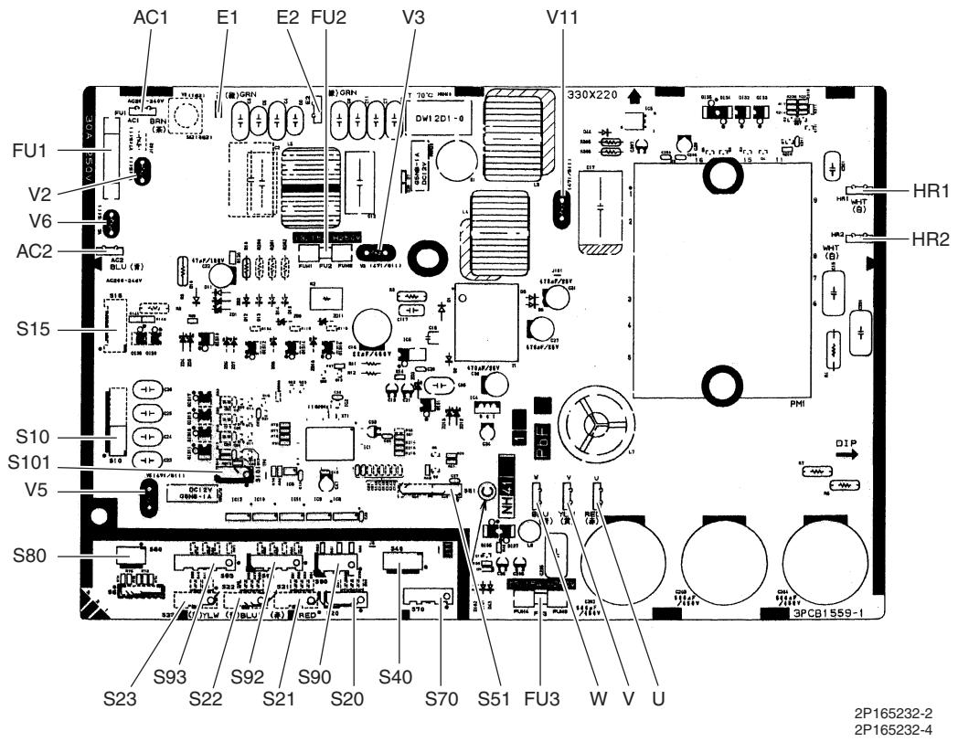
text_image
AC1 E1 E2 FU2 V3 V11 FU1 330X220 V2 V6 AC2 S15 S10 S101 V5 S80 S93 S22 S21 S20 S40 S70 S51 FU3 W V U S23 S22 S21 S20 S40 S70 S51 FU3 W V U 3PCB1559-1 HR1 HR2 DIP 2P165232-2 2P165232-4PCB (1): Main PCB (68/75 class)
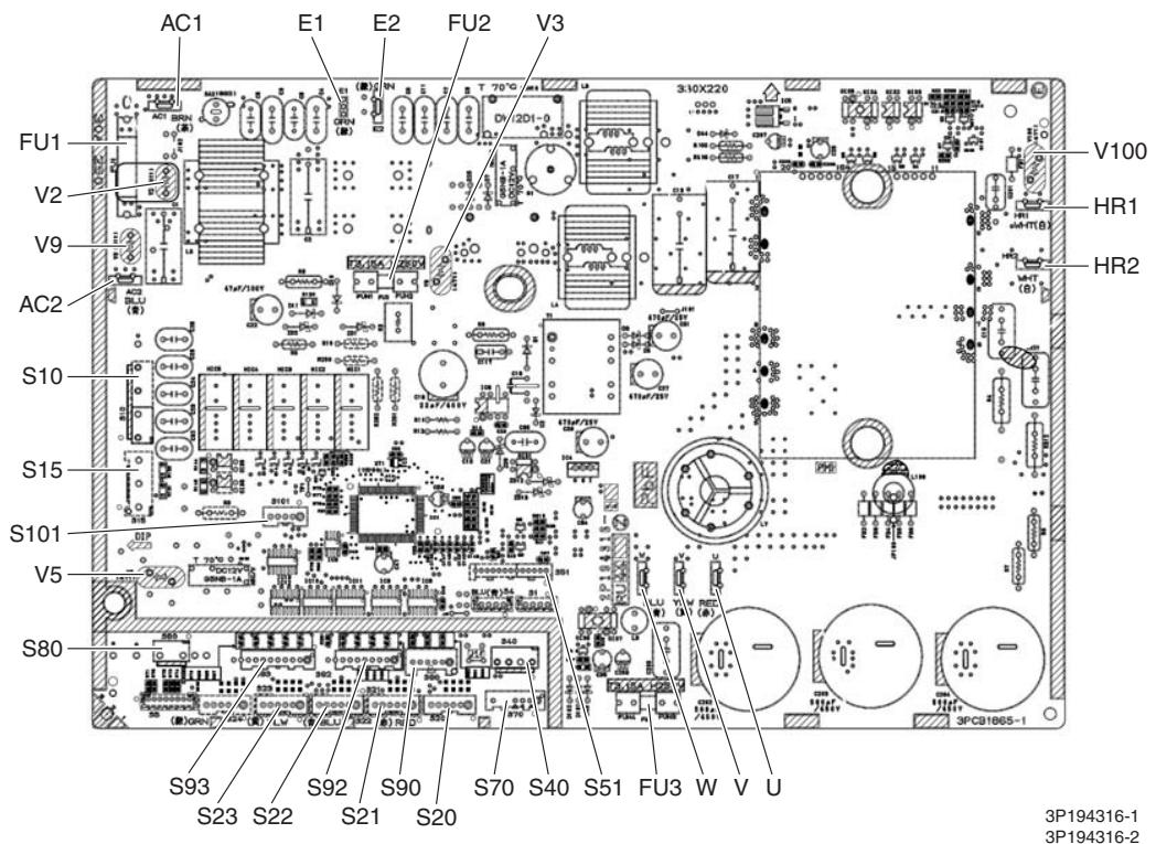
text_image
AC1 E1 E2 FU2 V3 3:10X220 FU1 V2 V9 AC2 S10 S15 S101 V5 S80 S93 S23 S22 S92 S21 S90 S20 S70 S40 S51 FU3 W V U 3P194316-1 3P194316-2PCB (1): Main PCB (80/90 class)
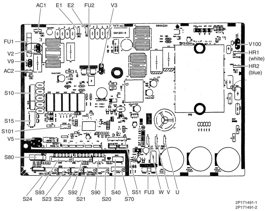
text_image
AC1 E1 E2 FU2 V3 FU1 V2 V9 AC2 S10 S15 S101 V5 S80 S93 S24 S23 S22 S92 S21 S90 S40 S70 S51 FU3 W V U 2P171491-1 2P171491-2 390X220 V100 HR1 (white) HR2 (blue)PCB (2): Service Monitor PCB (for 3 or 4-room model)
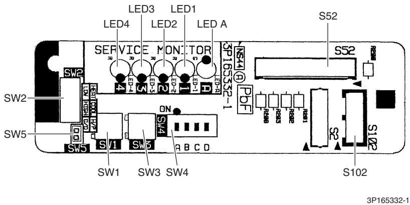
text_image
LED3 LED1 LED4 LED2 LED A SERVICE MONITOR SW2 SW5 SW1 SW3 SW4 S102 S102 S165332-1 S52 S52 R800 R800 R800 R800 R800 R800 R800 R800 R800 R800 R800 R800 R800 R800 R800 R800 R800 R800 R800 R800 R801 R801 R801 R801 R801 R801 R801 R801 R801 R801 R801 R801 R801 R801 R801 R801 R801 R801 R801 R801 R802 R802 R802 R802 R802 R802 R802 R802 R802 R802 R802 R802 R802 R802 R802 R802 R802 R802 R802 R802 R803 R803 R803 R803 R803 R803 R803 R803 R803 R803 R803 R803 R803 R803 R803 R803 R803 R803 R803 R803 R804 R804 R804 R804 R804 R804 R804 R804 R804 R804 R804 R804 R804 R804 R804 R804 R804 R804 R804 R804 S165332-1PCB (2): Service Monitor PCB (for 5-room model)
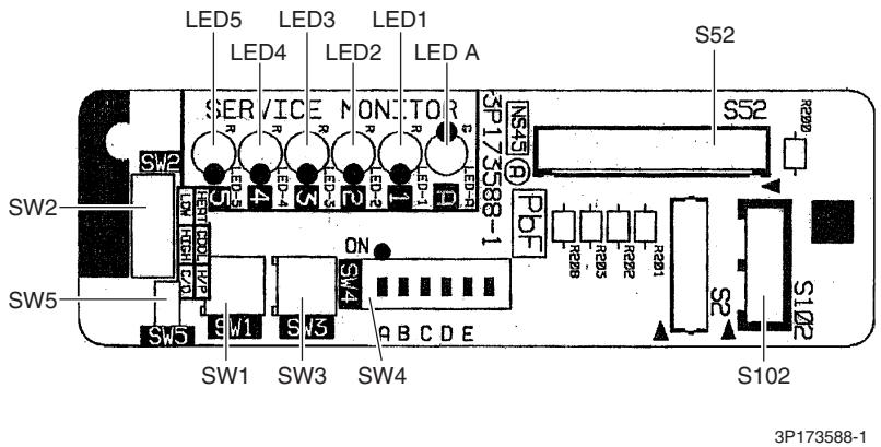
text_image
LED5 LED4 LED3 LED2 LED1 LED A SERVICER ON: TOR SP173588-1 S52 SW2 SW5 SW1 SW3 SW4 S102 3P173588-1 SW5 SW1 SW3 SW4 PDF RSB RSB RSB RSB RSB RSB RSB RSB RSB RSB RSB RSB RSB RSB RSB RSB RSB RSB RSB RSB RSB RSB RSB RSB RSB RSB RSB RSB RSB RSB2. Indoor Unit
2.1 FTXG25/35/50JV1BW(A)
Connectors and Other Parts
[A1P]: Control PCB
| 1) S21 | Connector for centralized control (HA) |
| 2) S25 | Connector for INTELLIGENT EYE sensor PCB |
| 3) S32 | Indoor heat exchanger thermistor |
| 4) S41 | Connector for swing motors |
| 5) S42 | Connector for reduction motor (front panel mechanism) and limit switch |
| 6) S46 | Connector for signal receiver / display PCB |
| 7) S200 | Connector for fan motor |
| 8) H1, H2, H3, FG | Connector for terminal board |
| 9) JB | Fan speed setting when compressor stops for thermostat OFF |
| JC | Power failure recovery function (auto-restart)* Refer to page 418 for detail. |
| 10) LED A | LED for service monitor (green) |
| 11) F1U | Fuse (3.15 A, 250 V) |
| 12) V1 | Varistor |
[A2P]: Signal Receiver / Display PCB
| 1) S51 | Connector for control PCB |
| 2) S52 | Connector for room temperature thermistor |
| 3) S1W | Forced cooling operation [ON/OFF] button |
| 4) H1P | LED for operation (multi-color) |
| 5) H2P | LED for INTELLIGENT EYE (green) |
| 6) JA | Address setting jumper* Refer to page 415 for detail. |
[A3P]: INTELLIGENT EYE Sensor PCB
| 1) S36 | Connector for control PCB |
PCB Detail
[A1P]: Control PCB
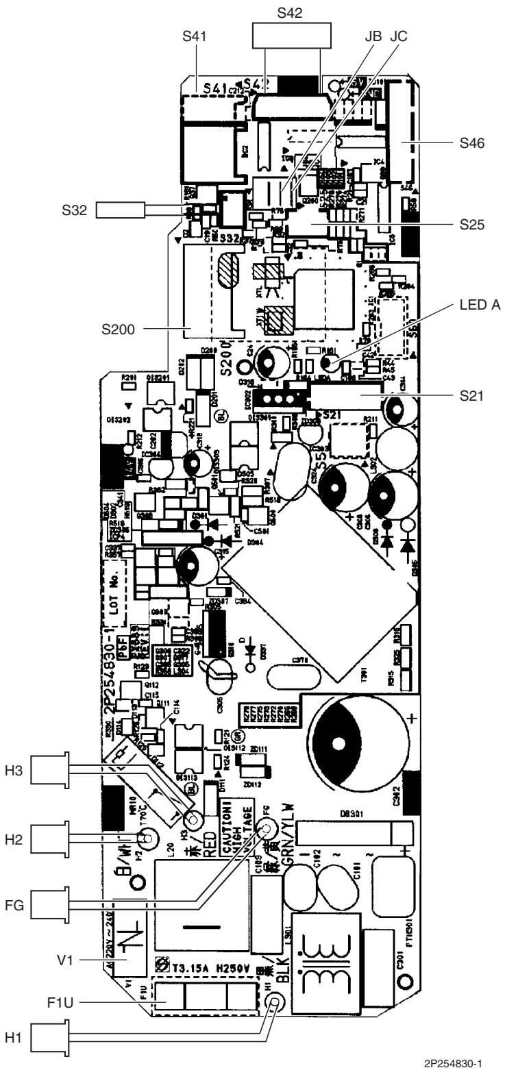
text_image
S41 S42 JB JC S46 S32 S25 S200 LED A S21 S20V D209 D212 D218 D221 D227 D232 D238 D244 D249 D255 D261 D267 D273 D279 D285 D291 D297 D303 D309 D315 D321 D327 D333 D339 D345 D351 D357 D363 D369 D375 D381 D387 D393 D399 D405 D411 D417 D423 D429 D435 D441 D447 D453 D459 D465 D471 D477 D483 D489 D495 D501 D507 D513 D519 D525 D531 D537 D543 D549 D555 D561 D567 D573 D579 D585 D591 D597 D603 D609 D615 D621 D627 D633 D639 D645 D651 D657 D663 D669 D675 D681 D687 D693 D699 D705 D711 D717 D723 D729 D735 D741 D747 D753 D760 D766 D772 D778<|box_end|><|ref_start|>text<|ref_end|><|rotate_up|> H3 2P254830-1 2P254830-1 2P254830-1 2P254830-1 2P254830-1 2P254830-1 2P254830-1 2P254830-1 2P254830-1 2P254830-1[A2P]: Signal Receiver / Display PCB
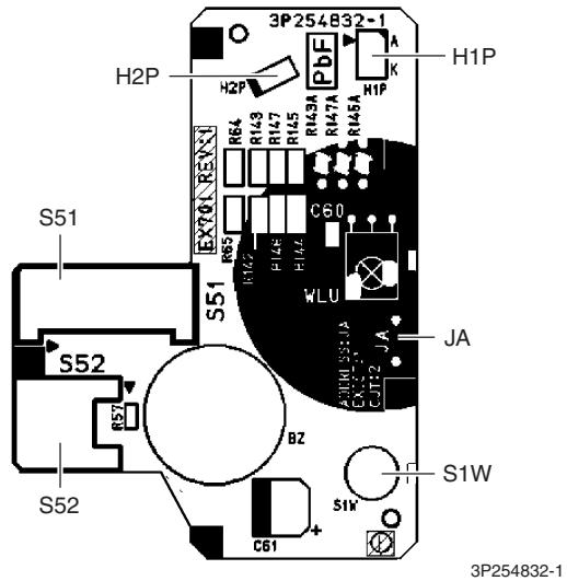
text_image
3P254832-1 H2P H2P PbF A K H1P R64 R143 R147 R145 R143A R147A R145A S51 S51 EX70/R50 R65 R142 R146 R144 C60 WLU JA S52 BZ S1W S52 C61 S1W 3P254832-1[A3P]: INTELLIGENT EYE Sensor PCB

text_image
S363P255914-1
2.2 FTXS20/25K2V1B, CTXS15/35K2V1B
Connectors and Other Parts
| PCB(1): Control PCB | |
| 1) S6 | Connector for swing motor (horizontal blade) |
| 2) S25 | Connector for INTELLIGENT EYE sensor PCB |
| 3) S26 | Connector for display PCB |
| 4) S32 | Connector for indoor heat exchanger thermistor |
| 5) S200 | Connector for fan motor |
| 6) S403 | Connector for adaptor PCB (option) |
| 7) FG1, FG2 | Connector for terminal board (frame ground) |
| 8) H1, H2, H3 | Connector for terminal board (indoor - outdoor transmission) |
| 9) V1 | Varistor |
| 10)JA | Address setting jumper* Refer to page 415 for detail. |
| 11)JB | Fan speed setting when compressor stops for thermostat OFF |
| JC | Power failure recovery function (auto-restart)* Refer to page 418 for detail. |
| 12)LED A | LED for service monitor (green) |
| 13)FU1 (F1U) | Fuse (3.15 A, 250 V) |
PCB (2): Display PCB
| 1) S27 | Connector for control PCB |
| 2) SW1 (S1W) | Forced cooling operation [ON/OFF] button |
| 3) LED1 (H1P) | LED for operation (green) |
| 4) LED2 (H2P) | LED for timer (yellow) |
| 5) LED3 (H3P) | LED for INTELLIGENT EYE (green) |
| 6) RTH1 (R1T) | Room temperature thermistor |
PCB (3): INTELLIGENT EYE Sensor PCB
| 1) S36 | Connector for control PCB |
PCB Detail
PCB(1): Control PCB
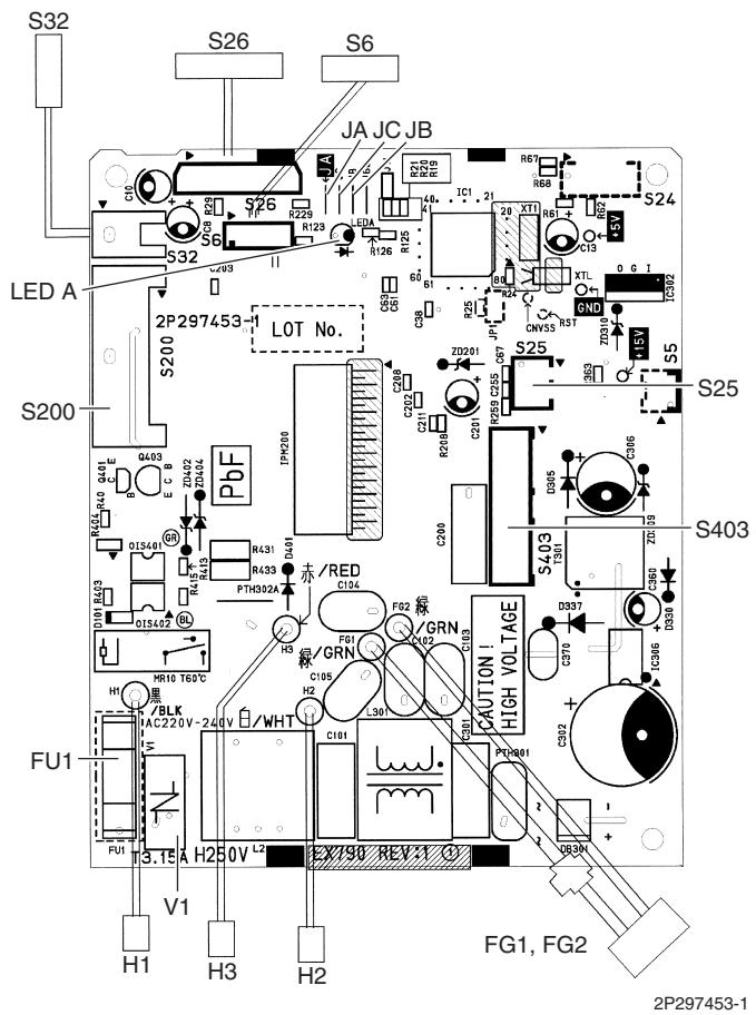
text_image
S32 S26 S6 JA JC JB LED A 2P297453 LOT No. S200 S24 S25 S403 FU1 FH V1 H1 H3 H2 HLK IAC 220V-240V WHT FR40 Q401 E C B R431 R433 R435 R436 R438 R439 R440 R441 R442 R443 R444 R445 R446 R447 R448 R449 R450 R451 R452 R453 R454 R455 R456 R457 R458 R459 R460 R461 R462 R463 R464 R465 R466 R467 R468 R469 R470 R471 R472 R473 R474 R475 R476 R477 R478 R479 R480 R481 R482 R483 R484 R485 R486 R487 R488 R489 R490 R491 R492 R493 R494 R495 R496 R497 R498 R499 R500 S200 S210 S220 S230 S240 S250 S260 S270 S280 S290 S300 S310 S320 S330 S340 S350 S360 S370 S380 S390 S400 S410 S420 S430 S440 S450 S460 S470 S480 S490 S500PCB(2): Display PCB
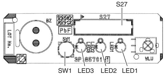
text_image
LOT No. BZ S27 BZ S27 PbF SW1 3P 85701 LED3 LED2 LED1 HLU(Solder side)
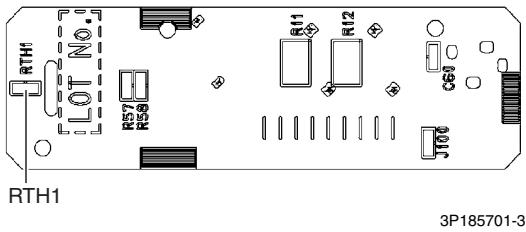
text_image
RTH1 LOT No. RTH1 3P185701-3PCB(3): INTELLIGENT EYE Sensor PCB
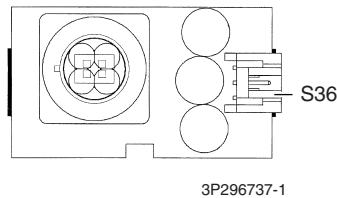
text_image
S36 3P296737-12.3 FTXS25/35/42/50J2V1B
Connectors and Other Parts
PCB (1): Control PCB
| 1) S1 | Connector for DC fan motor |
| 2) S21 | Connector for centralized control (HA) |
| 3) S25 | Connector for INTELLIGENT EYE sensor PCB |
| 4) S32 | Indoor heat exchanger thermistor |
| 5) S41 | Connector for swing motors |
| 6) S46 | Connector for display PCB |
| 7) S47 | Connector for signal receiver PCB |
| 8) H1, H2, H3, FG | Connector for terminal board |
| 9) JA | Address setting jumper* Refer to page 415 for detail. |
| 10) JB | Fan speed setting when compressor stops for thermostat OFF |
| JC | Power failure recovery function (auto-restart)* Refer to page 418 for detail. |
| 11) LED A | LED for service monitor (green) |
| 12) FU1 (F1U) | Fuse (3.15 A, 250 V) |
| 13) V1 | Varistor |
PCB (2): Signal Receiver PCB
| 1) S48 | Connector for control PCB |
PCB (3): Display PCB
| 1) S49 | Connector for control PCB |
| 2) SW1 | Forced cooling operation [ON/OFF] button |
| 3) LED1 (H1P) | LED for operation (green) |
| 4) LED2 (H2P) | LED for timer (yellow) |
| 5) LED3 (H3P) | LED for INTELLIGENT EYE (green) |
| 6) RTH1 (R1T) | Room temperature thermistor |
PCB (4): INTELLIGENT EYE Sensor PCB
| 1) S26 | Connector for control PCB |
PCB Detail
PCB (1): Control PCB
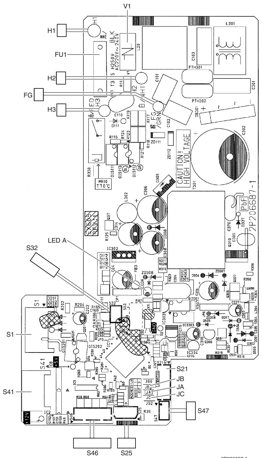
text_image
V1 H1 FU1 H2 FG H3 LED S32 S1 S41 S46 S25 L301 L20 C103 PTH301 C301 R115 R124 R123 R118 R121 R117 R17 R16 GRN C102 DB301 CAUTION! HIGH VOLTAGE T301 Q37 C314 D305 L302 C306 D308 IC302 IC308 IC309 IC305 C370 PbF D337 Q310 C305 R396 S21 JB JA JC S47 S41 S25 S46 S252P206687-1
PCB (2): Signal Receiver PCB
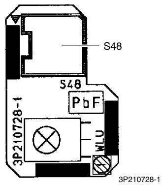
text_image
S48 S48 PbF 3P210728-1 MLU 3P210728-1PCB (3): Display PCB
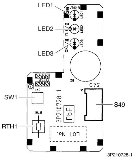
text_image
LED1 G/N LED1 LED2 YLY LED2 LED3 GRN ZB SW1 INS 3P210728-1 RTH1 3P210728-1 67S S49 L0T N°. RTH1PCB (4): INTELLIGENT EYE Sensor PCB
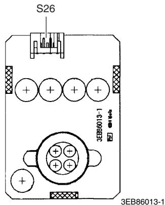
text_image
S26 3EB86013-1 3EB86013-12.4 FTXS60/71GV1B
Connectors and Other Parts
PCB (1): Control PCB
| 1) S1 | Connector for DC fan motor |
| 2) S21 | Connector for centralized control (HA) |
| 3) S25 | Connector for INTELLIGENT EYE sensor PCB |
| 4) S32 | Connector for indoor heat exchanger thermistor |
| 5) S41 | Connector for swing motors |
| 6) S46 | Connector for display PCB |
| 7) S47 | Connector for signal receiver PCB |
| 8) H1, H2, H3, FG | Connector for terminal board |
| 9) V1 | Varistor |
| 10)JA | Address setting jumper* Refer to page 415 for detail. |
| 11) JB | Fan speed setting when compressor stops for thermostat OFF |
| JC | Power failure recovery function (auto-restart)* Refer to page 418 for detail. |
| 12)LED A | LED for service monitor (green) |
| 13)FU1 (F1U) | Fuse (3.15 A, 250 V) |
PCB (2): Signal Receiver PCB
| 1) S48 | Connector for control PCB |
PCB (3): Display PCB
| 1) S49 | Connector for control PCB |
| 2) SW1 | Forced cooling operation [ON/OFF] button |
| 3) LED1 (H1P) | LED for operation (green) |
| 4) LED2 (H2P) | LED for timer (yellow) |
| 5) LED3 (H3P) | LED for INTELLIGENT EYE (green) |
| 6) RTH1 (R1T) | Room temperature thermistor |
PCB (4): INTELLIGENT EYE Sensor PCB
| 1) S36 | Connector for control PCB |
PCB Detail
PCB (1): Control PCB
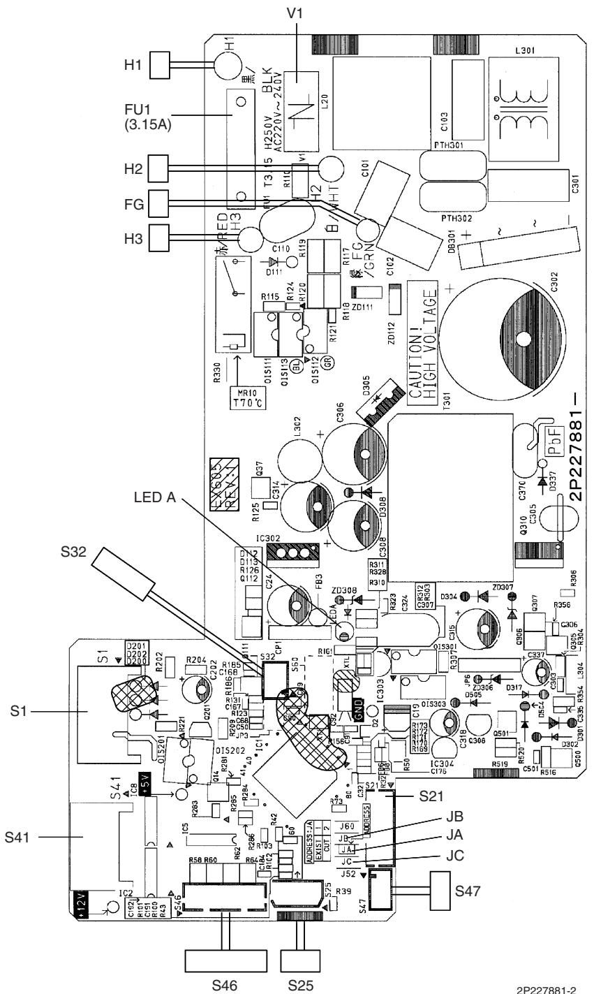
text_image
V1 H1 FU1 (3.15A) H2 FG H3 L301 L20 C103 PTH301 C301 R115 R124 R120 R119 R118 R117 R116 R115 R114 R113 R112 R111 R109 R108 R107 R106 R105 R104 R103 R102 R101 R99 R98 R97 R96 R95 R94 R93 R92 R91 R90 R89 R88 R87 R86 R85 R84 R83 R82 R81 R80 R79 R78 R77 S46 S25 2P227881-2 LED A S32 S1 S41 S47 S21 JB JA JC S46 S25PCB (2): Signal Receiver PCB
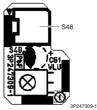
text_image
S48 548 C61 WLU 3P247309-1 3P247309-1PCB (3): Display PCB
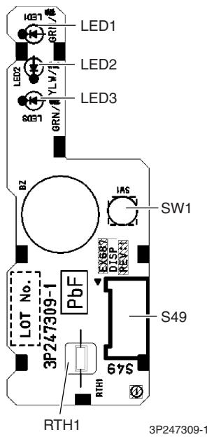
text_image
LED1 LED2 LED3 BZ INS SW1 EX683 DTSP REXN S49 3P247309-1 PbF LOT No. 3P247309-1 RTH1 64S 3P247309-1PCB (4): INTELLIGENT EYE Sensor PCB
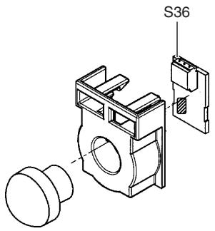
text_image
S363P227885-1
2.5 FVXG25/35/50K2V1B
Connectors and Other Parts
| PCB (1): Main PCB | |
| 1) S1 | Connector for fan motor |
| 2) S2 | Connector for terminal board |
| 3) S6 | Connector for swing motor |
| 4) S21 | Connector for centralized control (HA) |
| 5) S26 | Connector for service PCB |
| 6) S30 | Connector for indoor electronic expansion valve coil (motor operated valve coil) |
| 7) S32 | Connector for indoor heat exchanger thermistor |
| 8) S33 | Connector for room temperature thermistor |
| 9) S34 | Connector for radiant panel thermistors |
| 10)S46 | Connector for display PCB |
| 11)FG | Connector for earth |
| 12)V1 | Varistor |
| 13)JB | Fan speed setting when compressor stops for thermostat OFF |
| JC | Power failure recovery function* Refer to page 418 for detail. |
| 14)F1U | Fuse (3.15A, 250V) |
| 15)LED A | LED for service monitor (green) |
PCB (2): Display PCB
| 1) S56 | Connector for main PCB |
| 2) S1W | Forced cooling operation [ON/OFF] button |
| 3) H1P | LED for operation (green) |
| 4) H2P | LED for timer (yellow) |
| 5) H3P | LED for RADIANT operation (red) |
PCB (3): Service PCB
| 1) S27 | Connector for main PCB |
| 2) S2W-1 | Address setting switch* Refer to page 415 for detail.* Keep the other switches as factory setting (OFF). |
PCB Detail
PCB (1): Main PCB
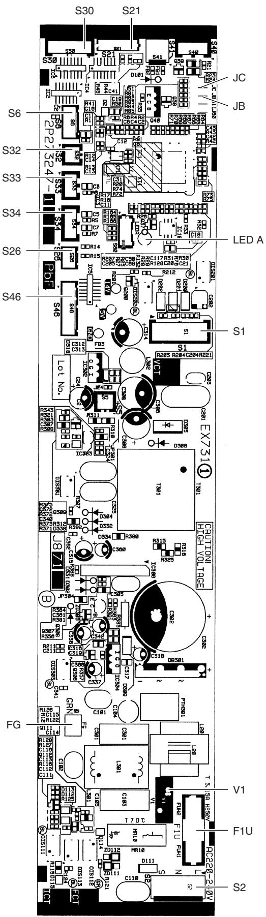
text_image
S2 F1U V1 NC220-2 RC220-2 S1 EX751 CUTION HIGH VOLTAGE P1H301 L28 T 1.58 HRSV V1 CN S B1 D11 M10 R10 M10 G10 S10 R16 C20 C20 C20 C20 C20 C20 C20 C20 C20 C20 C20 C20 C20 C20 C20 C20 C20 C20 C20 C20 C20 C20 C20 C20 C20 C25 C25 C25 C25 C25 C25 C25 C25 C25 C25 C25 C25 C25 C25 C25 C25 C25 C25 C25 C25 C25 C25 C25 C25 C25 C20 C20 C20 C20 C20 C20 C20 C20 C20 C20 C20 C20 C20 C20 C20 C20 C20 C20 C20 C20 C20 C20 C20 C46 S46 S26 S34 S33 S32 S31 S30 S39 S48 S46 S46 S46 S46 S46 S46 S46 S46 S46 S46 S46 S46 S46 S46 S46 S46 S46 S462P273247-1
PCB (2): Display PCB
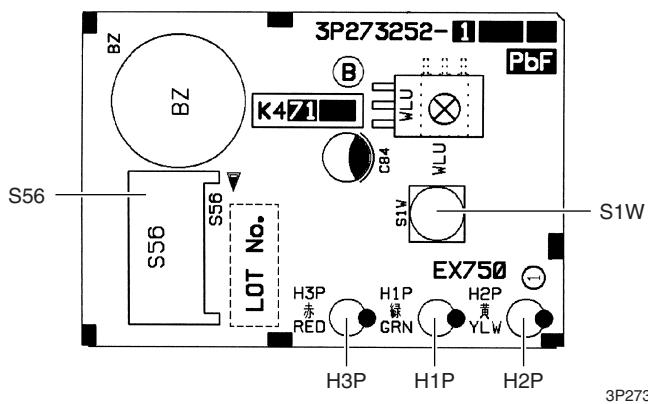
text_image
3P273252-1 BZ K471 B WLU C84 WLU S1W S56 S56 LOT No. EX750 H3P 赤 RED H1P 绿 GRN H2P 黄 YLW H3P H1P H2P 3P273PCB (3): Service PCB
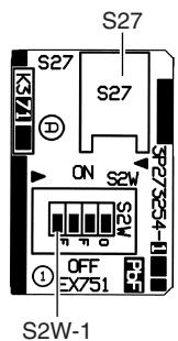
text_image
S27 S27 S27 S27 S27 S27 S27 S27 S27 S27 S27 S27 S27 S27 S27 S27 S27 S27 S27 S27 S27 S27 S27 S27 S27 S273P273254-1
2.6 FVXS25/35/50FV1B
Connectors and Other Parts
PCB (1): Sensor PCB
1) S49 Connector for control PCB
2) RTH2 (R1T) Room temperature thermistor
PCB (2): Control PCB
1) S1 Connector for fan motor
2) S21 Connector for centralized control (HA)
3) S26 Connector for service PCB
4) S32 Indoor heat exchanger thermistor
5) S41 Connector for lower air outlet motor
6) S42 Connector for swing motor
7) S46 Connector for display PCB
8) S48 Connector for sensor PCB
9) H1, H2, H3 Connector for terminal board
10)E1 Terminal for earth
11)V1, V2 Varistor
12)JA Address setting jumper * Refer to page 415 for detail.
13)JB Fan speed setting when compressor stops for thermostat OFF
JC Power failure recovery function
* Refer to page 418 for detail.
14) FU1 (F1U) Fuse (3.15A, 250V)
15) LED A LED for service monitor (green)
PCB (3): Service PCB
1) S27 Connector for control PCB
2) SW2-4 Switch for upward airflow limit setting
* Refer to page 418 for detail.
* Keep the other switches as factory setting.
3) SW4 (S4W) Switch for air outlet selection
* Refer to page 185, 195 for detail.
PCB (4): Display PCB
1) S47 Connector for control PCB
2) SW1 (S1W) Forced cooling operation [ON/OFF] button
3) LED1 (H1P) LED for operation (green)
4) LED2 (H2P) LED for timer (yellow)
PCB Detail
PCB (1): Sensor PCB
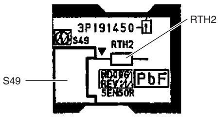
text_image
3P191450 S49 RTH2 RD0V6 REV:1/2 PbF SENSOR S49 RTH23P191450-1
PCB (2): Control PCB
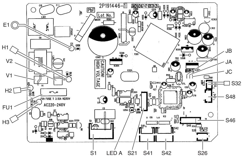
text_image
2P191446-1 MD006-T-BCV3 PbF Lot No. CB301 R353 C30 7 C35 8 C35 8 C35 8 C35 8 C35 8 C35 8 C35 8 C35 8 C35 8 C35 8 C35 8 C35 8 C35 8 C35 8 C35 8 C35 8 C35 8 C301 L302 IC302 H1 V2 V1 H2 FU1 FU1 FUSE T 3.15A H250V AC220-240V H3 S1 LED A S21 S41 S42 S46 S26 JB JA JC S32 S48 S462P191446-1
PCB (3): Service PCB
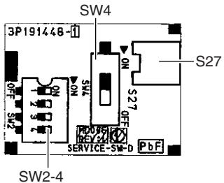
text_image
SW4 3P191448-1 S27 SW2-4 S27 SERVICE-SW-D PbF3P191448-1
PCB (4): Display PCB
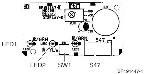
text_image
3P19147-1 MD00G REV32 DISPLAY-D PbF GND VCC VOUT + C75 BZ1 LED1 绿/GRN LED2 5W 黄 YLW 量/GRN S47 LED3 LED2 SW1 S47 3P191447-1★ LED3 does not function.
2.7 FLXS25/35/50/60BAVMB
Connectors and Other Parts
PCB (1): Control PCB
| 1) S6 | Connector for swing motor (horizontal swing) |
| 2) S7 | Connector for AC fan motor |
| 3) S21 | Connector for centralized control (HA) |
| 4) S24 | Connector for display PCB |
| 5) S26 | Connector for signal receiver PCB |
| 6) S32 | Connector for indoor heat exchanger thermistor |
| 7) S37 | Connector for power supply PCB |
| 8) JA | Address setting jumper* Refer to page 415 for detail. |
| 9) JB | Fan speed setting when compressor stops for thermostat OFF |
| JC | Power failure recovery function* Refer to page 418 for detail. |
| 10) SW2 | Select switch for installation (ceiling or floor)* Refer to page 418 for detail. |
| 11) LED A | LED for service monitor (green) |
PCB (2): Power Supply PCB
| 1) S36 | Connector for control PCB |
| 2) H1, H2, H3 | Connector for terminal board |
| 3) H4, H5, H6 | Connector for AC fan motor |
| 4) V1 | Varistor |
| 5) FU1 | Fuse (3.15A, 250V) |
PCB (3): Display PCB
| 1) S25 | Connector for control PCB |
| 2) LED1 (H1P) | LED for operation (green) |
| 3) LED2 (H2P) | LED for timer (yellow) |
| 4) LED3 (H3P) | LED for HOME LEAVE operation (red) |
PCB (4): Signal Receiver PCB
| 1) S27 | Connector for control PCB |
| 2) S31 (RTH) | Room temperature thermistor |
| 3) SW1 (S1W) | Forced cooling operation [ON/OFF] button |
PCB Detail
PCB (1): Control PCB
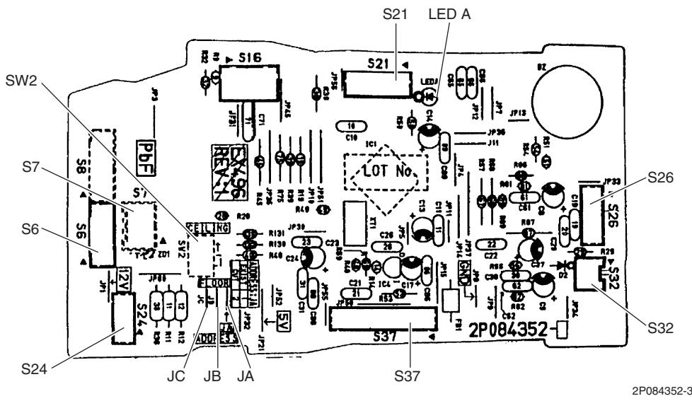
text_image
SW2 S7 S6 S24 JC JB JA S16 S21 LED A S21 10 C10 IC1 R20 R131 R130 R40 C24 C23 C21 C19 C18 C17 C16 C15 C14 C13 C12 C11 C10 C9 C8 C7 C6 C5 C4 C3 C2 C1 S26 S26 S32 S32 S37 2P084352- 2P084352-3PCB (2): Power Supply PCB
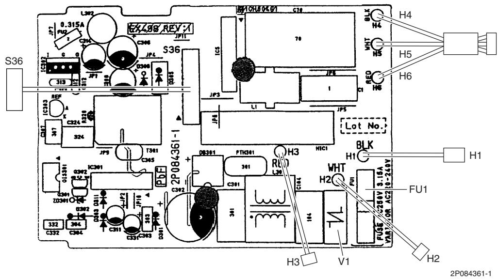
text_image
S36 L302 0.315A FU2 C306 C306 JP11 IC302 313 REF IC303 A K C324 324 C301 ZD301 C302 C301 C302 C301 C301 C302 C301 C302 C301 C302 C301 C302 C301 C302 C301 C302 C301 C302 C301 C302 C301 C302 C301 C302 C301 C301 C302 C301 C302 C301 C302 C301 C302 C301 C302 C301 C302 C301 C302 C301 T361 C305 JPS T361 JPS JPS L1 JP5 JP6 JP7 JP8 JP9 JP10 JP11 JP12 JP13 JP14 JP15 JP16 JP17 JP18 JP19 JP20 JP21 JP22 JP23 JP24 JP25 JP26 JP27 JP28 JP29 JP30 JP31 JP32 JP33 JP34 JP35 JP36 JP37 JP38 JP39 JP40 JP41 JP42 JP43 JP44 JP45 JP46 JP47 JP48 JP49 JP50 JP51 JP52 JP53 JP54 JP55 JP56 JP57 JP58 JP59 JP60 JP61 JP62 JP63 JP64 JP65 JP66 JP67 JP68 JP69 JP70 H4 H5 H6 Lot No. BLK H1 H2 FU1 V1 H3 V1 H2PCB (3): Display PCB
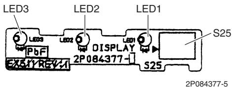
text_image
LED3 LED2 LED1 S25 LED3 LED2 LED1 PbF DISPLAY 2P084377- S25 EX51Y REV-A 2P084377-5PCB (4): Signal Receiver PCB
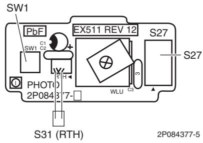
text_image
SW1 PbF EX511 REV 12 S27 SW1 C1 SW1 C2 PHOTO 2P08437-7- S31 (RTH) WLU C3 S27 2P084377-52.8 FDXS25/35E7VMB, FDXS50/60C7VMB
Connectors and Other Parts
PCB (1): Control PCB
| 1) S1 | Connector for AC fan motor |
| 2) S7 | Connector for AC fan motor (Hall IC) |
| 3) S21 | Connector for centralized control (HA) |
| 4) S26 | Connector for display PCB |
| 5) S32 | Connector for indoor heat exchanger thermistor |
| 6) H1, H2, H3 | Connector for terminal board |
| 7) GND | Connector for terminal board (earth) |
| 8) JA | Address setting jumper* Refer to page 415 for detail. |
| 9) JB | Fan speed setting when compressor stops for thermostat OFF |
| JC | Power failure recovery function (auto-restart)Refer to page 418 for detail. |
| 10) LED A | LED for service monitor (green) |
| 11) FU1 (F1U) | Fuse (3.15A, 250V) |
| 12) V1 (V1TR) | Varistor |
PCB (2): Display PCB
| 1) S1 | Connector for control PCB |
| 2) SW1 (S1W) | Forced cooling operation [ON/OFF] button |
| 3) LED1 (H1P) | LED for HOME LEAVE operation (red) |
| 4) LED2 (H2P) | LED for timer (yellow) |
| 5) LED3 (H3P) | LED for operation (green) |
| 6) RTH1 (R1T) | Room temperature thermistor |
PCB Detail
PCB (1): Control PCB
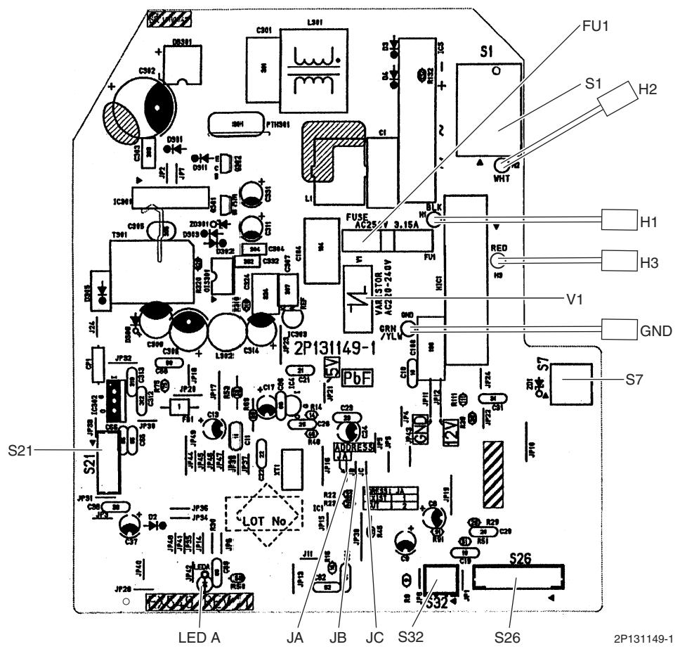
text_image
S21 S21 LED A JA JB JC S32 S26 2P131149-1 S7 FU1 S1 H2 H1 H3 V1 GND S1 O C301 L301 C302 D8301 C303 D301 D501 D502 D503 D504 D505 D506 D507 D508 D509 D510 D511 D512 D513 D514 D515 D516 D517 D518 D519 D520 D521 D522 D523 D524 D525 D526 D527 D528 D529 D530 D531 D532 D533 D534 D535 D536 D537 D538 D539 D540 D541 D542 D543 D544 D545 D546 D547 D548 D549 D550 D551 D552 D553 D554 D555 D556 D557 D558 D559 D560 D561 D562 D563 D564 D565 D566 D567 D568 D569 D570 D571 D572 D573 D574 D575 D576 D577 D578 D579 D580 D581 D582 D583 D584 D585 D586 D587 D588 D589 D590 D591 D592 D593 D594 D595 D596 D597 D598 D599 D600 FUSE AC2 2/1 3.15A H L K FUT 1STOR GRN CHI GND S7 S26 S26 S26 S26 S26 S26 S26 S26 S26 S26 S26 S26 S26 S26 S26 S26 S26 S26 S26 S26 S26 S26 S26 S26 S26 S26 S26 S26 S26 S26 S26 S26 S26 S26PCB (2): Display PCB
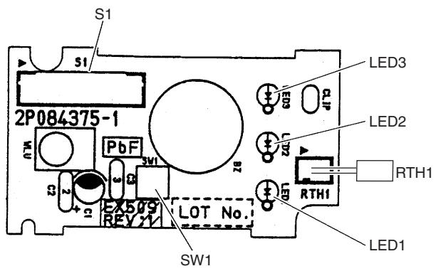
text_image
S1 S1 2P084375-1 LED3 LED2 RTH1 EX509 LOT No. SW1 SW1 PbF SW1 RTH1 LED12P084375-1
2.9 FCQG35/50/60FVEB
Connectors and Other Parts
[A1P]
1) X15A Connector for float switch
2) X16A Connector for room temperature thermistor
3) X17A, X18A Connector for indoor heat exchanger thermistor
4) X20A Connector for fan motor
5) X24A Connector for signal receiver PCB
(when the wireless remote controller is used)
6) X27A Connector for terminal board (for inter-unit wiring)
7) X30A Connector for terminal board (for wired remote controller)
8) X33A Connector for wiring adaptor PCB (option)
9) X35A Connector for group control adaptor (option)
10) X36A Connector for self-cleaning decoration panel (option)
11) X65A, X70A Connector for [A2P]
12) HAP LED for service monitor (green)
13) SS1 Selector switch for emergency
[A2P]
1) X1A, X7A Connector for [A1P]
2) X2A Connector for sensor kit (option)
3) X4A Connector for humidity sensor PCB [A3P]
4) X8A Connector for self-cleaning decoration panel (option)
5) X9A Connector for swing motors
6) X10A Connector for drain pump motor
7) HAP LED for service monitor (green)
[A3P]: Humidity Sensor PCB
1) CN1 Connector for [A2P]
PCB Detail
[A1P]
![DAIKIN FVXM-F/FVXS-F - [A3P]: Humidity Sensor PCB - 1](/content/2020/11/206417/images/d0d935bc07c2d2b59b68202bbd73fe798648acc377a28c1391d598667614614e.jpg)
text_image
X27A X27A X65A X20A SS1 X35A X33A HAP X70A X17A X30A X30A R/C D3 XT X24A X15A X18A X16A X36A X30A X24A X15A X18A X16A X36A X20R WHB WHB WHB WHB WHB WHB WHB WHB WHB WHB WHB WHB WHB WHB WHB WHB WHB WHB WHB WHB WHB WHB WHB WHB WHB WHB WHB WHB WHB WHB WHB WHB WHB WHB2P263068-4
[A2P]
![DAIKIN FVXM-F/FVXS-F - [A3P]: Humidity Sensor PCB - 2](/content/2020/11/206417/images/35a424c094e4826f953ae767950c79329a16c12dca57030e689cf074aa4dcb73.jpg)
Connectors and Other Parts
[A1P]: Control PCB
| 1) X5A | Connector for terminal board (for wired remote controller) |
| 2) X10A, X11A | Connector for transformer |
| 3) X15A | Connector for float switch |
| 4) X17A, X18A | Connector for indoor heat exchanger thermistor |
| 5) X19A | Connector for room temperature thermistor |
| 6) X20A | Connector for fan motor |
| 7) X24A | Connector for signal receiver PCB(when the wireless remote controller is used) |
| 8) X25A | Connector for drain pump motor |
| 9) X27A | Connector for terminal board (for inter-unit wiring) |
| 10) X33A | Connector for wiring adaptor PCB (option) |
| 11) X35A | Connector for group control adaptor (option) |
| 12) X36A | Connector for swing motor |
| 13) X40A | Connector for ON/OFF input from outside (option) |
| 14) X60A, X61A | Connector for interface adaptor (option) |
| 15) HAP | LED for service monitor (green) |
| 16) SS1 | Selector switch for emergency |
PCB Detail
[A1P]: Control PCB
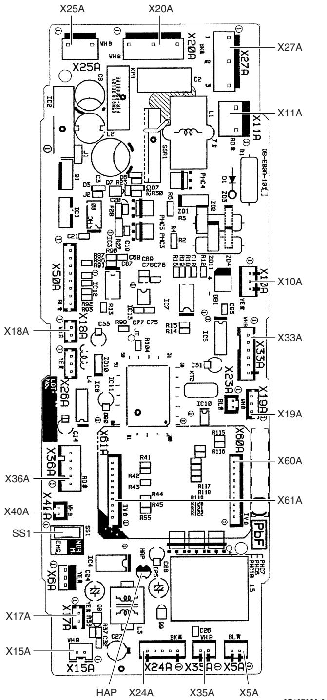
Connectors and Other Parts
[A1P]: Control PCB
| 1) X5A | Connector for terminal board (for wired remote controller) |
| 2) X10A, X11A | Connector for transformer |
| 3) X14A | Connector for limit switch (for swing flap) |
| 4) X15A | Connector for float switch (option) |
| 5) X17A, X18A | Connector for indoor heat exchanger thermistor |
| 6) X19A | Connector for room temperature thermistor |
| 7) X20A, X26A | Connector for fan motor |
| 8) X24A | Connector for signal receiver PCB(when the wireless remote controller is used) |
| 9) X25A | Connector for drain pump motor (option) |
| 10) X27A | Connector for terminal board (for inter-unit wiring) |
| 11) X29A | Connector for swing motor |
| 12) X33A | Connector for wring adaptor PCB (option) |
| 13) X35A | Connector for group control adaptor (option) |
| 14) X40A | Connector for ON/OFF input from outside (option) |
| 15) X60A, X61A | Connector for interface adaptor (option) |
| 16) HAP | LED for service monitor (green) |
| 17) SS1 | Selector switch for emergency |
PCB Detail
[A1P]: Control PCB
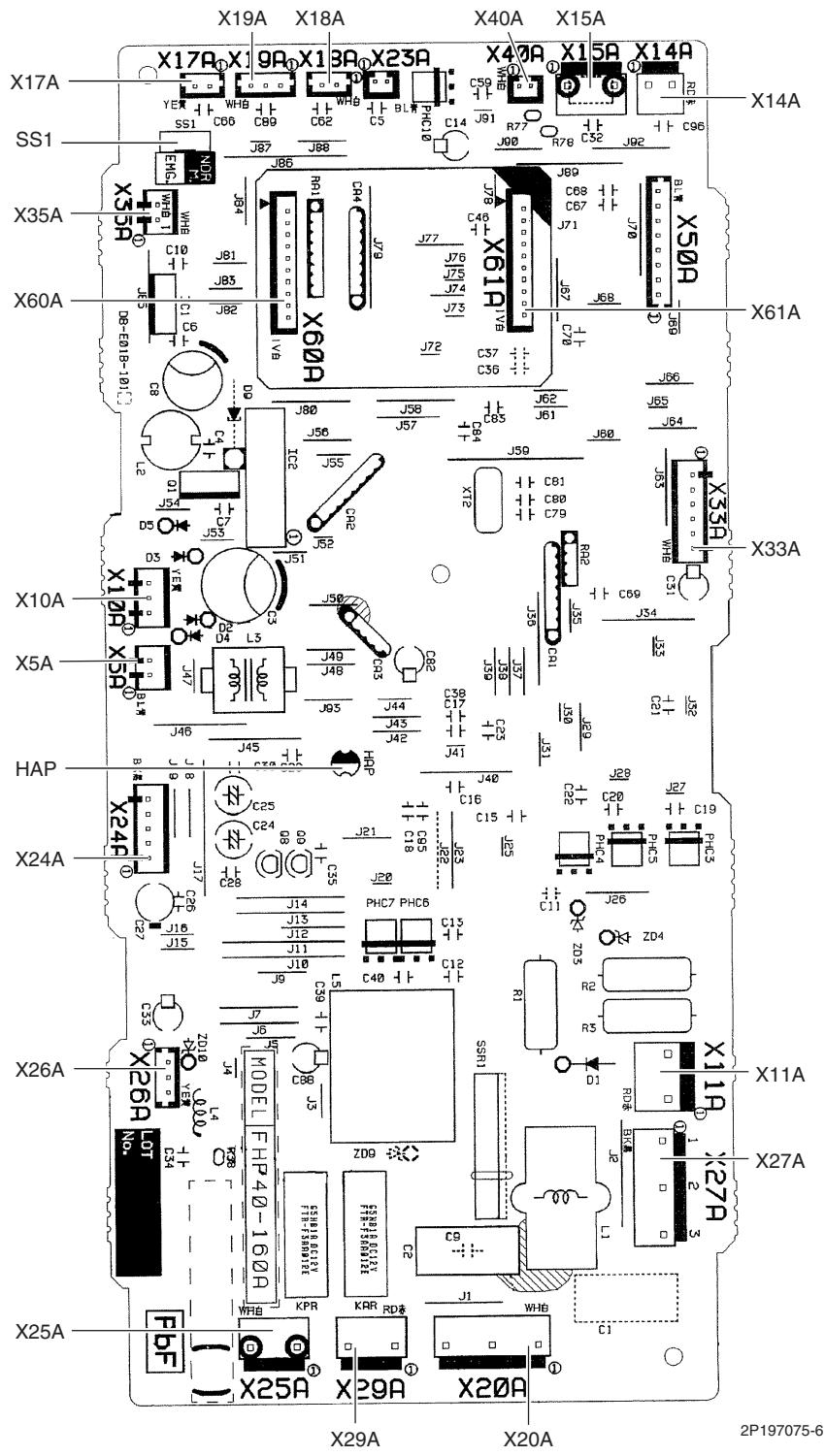
text_image
X19A X18A X40A X15A X17A X17R-X1 9A-X1 3A-X23A X40A X15A X14A YER WHB C66 C89 WHB BL PHC10 C59 R77 C52 J92 C96 X14A SS1 EMF NDR J87 J88 J86 J87 X35A X35R WHB C10 J81 J85 J86 X60A C1 C6 J82 V8 X60A X61A X61A X60A B-E01-B-101C D0 J80 J58 J62 J66 J65 X10A X12R YER D2 L3 J50 J56 J57 C64 J61 J60 J63 X5A X5R B1W J47 J49 J48 C38 C17 J39 J37 J30 J29 HAP B J46 J45 HAD P J40 J41 C16 C15 J25 J28 ZD4 R2 R5 D1 D1 RDK BKSA X1 1A X11A X27A X24A X24P C25 C24 J21 PHC7 PHC6 C13 C12 R1 SS31 X27A X26A X26A LOT YER L4 FHP40-160A KPR KAR RDK C9 C2 J1 WHB C1 X25A FBF X25A X29A X20A X29A X20A 2P197075-62.12 FDBQ25B8V1
Connectors and Other Parts
[A1P]: Control PCB
| 1) X5A | Connector for terminal board (for wired remote controller) |
| 2) X10A, X11A | Connector for transformer |
| 3) X17A | Connector for indoor heat exchanger thermistor |
| 4) X18A | Connector for liquid pipe thermistor |
| 5) X19A | Connector for room temperature thermistor |
| 6) X21A | Connector for fan motor |
| 7) X27A | Connector for terminal board (for inter-unit wiring) |
| 8) X33A | Connector for wiring adaptor PCB (option) |
| 9) X35A | Connector for group control adaptor (option) |
| 10) X40A | Connector for ON/OFF input from outside (option) |
| 11) X60A, X61A | Connector for interface adaptor (option) |
| 12) HAP | LED for service monitor (green) |
| 13) SS1 | Selector switch for emergency |
PCB Detail
[A1P]: Control PCB
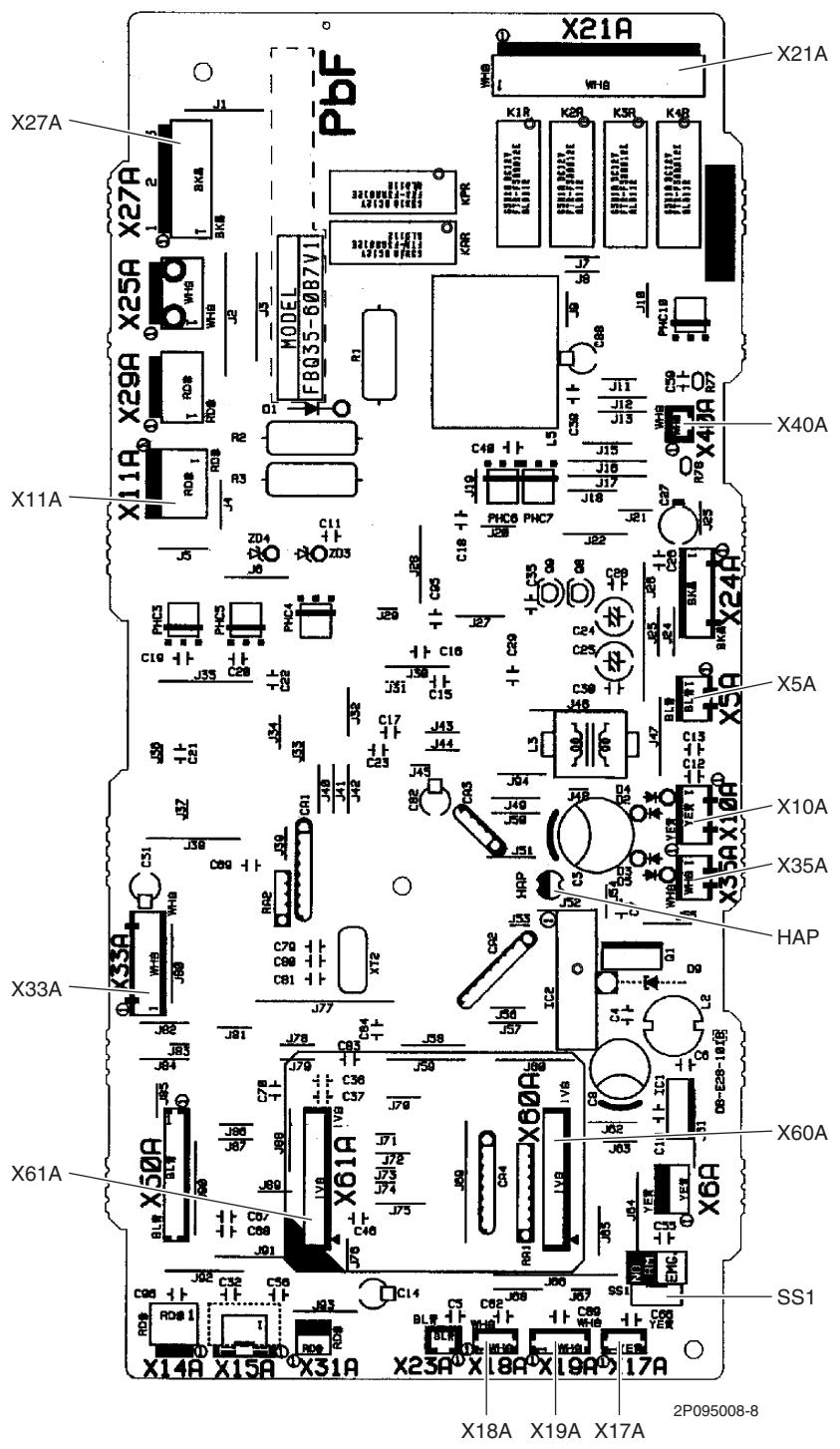
text_image
X27A X29A X25A X27A PbF X11A X40A X10A X35A HAP X60A SS1 X18A X19A X17A 2P095008-8 X14A X15A X31A X23A X18A X19A 17A2.13 FBQ35/50/60C8VEB
Connectors and Other Parts
[A1P]: Control PCB
| 1) X15A | Connector for float switch |
| 2) X16A | Connector for room temperature thermistor |
| 3) X17A | Connector for indoor heat exchanger thermistor |
| 4) X18A | Connector for liquid pipe thermistor |
| 5) X25A | Connector for drain pump motor |
| 6) X27A | Connector for terminal board (for inter-unit wiring) |
| 7) X28A | Connector for power supply wiring (option) |
| 8) X30A | Connector for terminal board (for wired remote controller) |
| 9) X33A | Connector for wiring adaptor PCB (option) |
| 10) X35A | Connector for group control adaptor (option) |
| 11) X70A | Connector for fan PCB |
| 12) X85A | Connector for multi zoning (option) |
| 13) HAP | LED for service monitor (green) |
| 14) SS1 | Selector switch for emergency |
[A2P]: Fan PCB (for FBQ35/50C8VEB)
| 1) X3A | Connector for control PCB |
| 2) X6A | Connector for reactor |
| 3) X8A | Connector for fan motor |
| 4) X10A | Connector for terminal board (power supply) |
| 5) F2U | Fuse (5 A, 250 V) |
| 6) F4U | Fuse (6.3 A, 250 V) |
| 7) HAP | LED for service monitor (green) |
[A2P]: Fan PCB (for FBQ60C8VEB)
| 1) X1A, X2A | Connector for fan motor |
| 2) X3A | Connector for control PCB |
| 3) X6A | Connector for reactor |
| 4) X9A | Connector for capacitor PCB |
| 5) X10A | Connector for terminal board (power supply) |
| 6) F3U | Fuse (6.3 A, 250 V) |
| 7) HAP | LED for service monitor (green) |
[A3P]: Capacitor PCB (FBQ60C8VEB only)
text_image
PbF T41③ R3 SPCB2009-1 C3 PC780-1(A)Connector for X9A on fan PCB
3P217472-1
PCB Detail
[A1P]: Control PCB
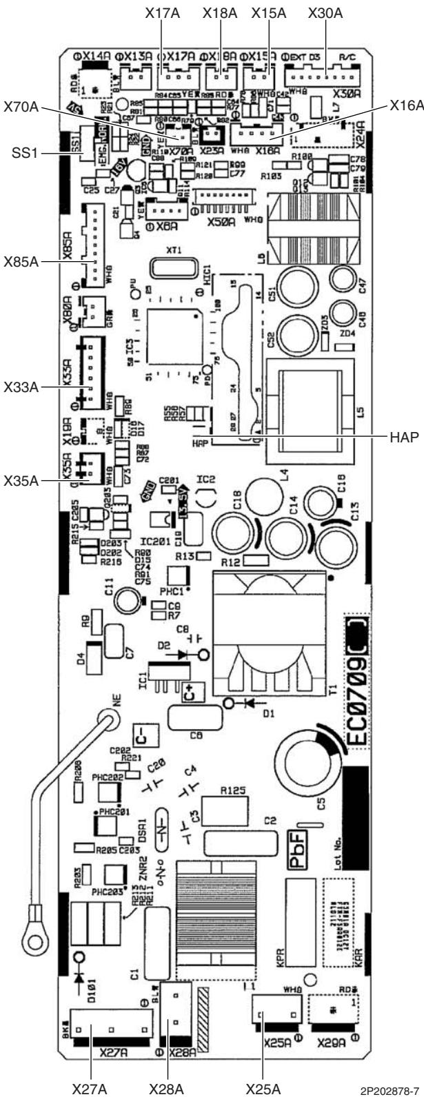
text_image
X17A X18A X15A X30A X70A SS1 X65A X85A X33A X35A X27A X28A X25A 2P202878-7 X25A X29A EC0709[0] X27A X28A X25A 2P202878-7[A2P]: Fan PCB (for FBQ35/50C8VEB)
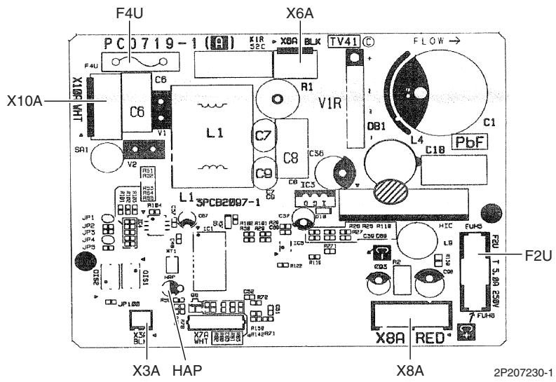
text_image
F4U X6A PC 0719-1 (R) K1R S2C X8A BLK TV41 C FLOW → X10A C6 R1 V1R L1 C7 C8 C9 IC3 C56 DB1 L4 PbF C1 L1 SPCB2007-1 R1B R1B R1B R1B R1B R1B R1B R1B R1B R1B R1B R1B R1B R1B R1B R1B R1B R1B R1B R1B R1B R1B R1B R1B R1B R1B R1B R1B R1B R1B R1B R1B R1B R1B R4U F2U X8A RED X3A HAP X8A 2P207230-1[A2P]: Fan PCB (for FBQ60C8VEB)
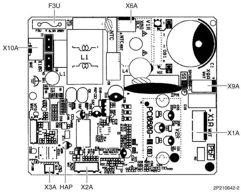
text_image
F3U X6A X10A X9A X1A X3A HAP X2A 2P210642-23. Wired Remote Controller
3.1 BRC1D528
Connectors and Other Parts
1) P1, P2
Terminal for indoor unit
2) R1T
Room temperature thermistor
3) SS1
MAIN / SUB setting switch
* Refer to page 422 for detail.
PCB Detail
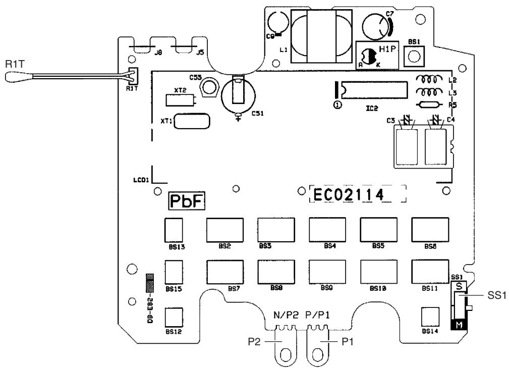
text_image
R1T J8 J5 C9 L1 C7 H1P BS1 R K XT2 XT1 C55 C51 IC2 L2 L3 R5 C3 N C4 LCD1 PbF EC02114 BS13 BS2 BS3 BS4 BS5 BS6 BS15 BS7 BS8 BSQ BS10 BS11 DB-E82- N/P2 P/P1 BS12 P1 P2 P1 BS14 M SS12P113638-2
3.2 BRC1E52A7, BRC1E52B7
Connectors and
Other Parts
1) P1, P2
2) R1T
Terminal for indoor unit
Room temperature thermistor
PCB Detail
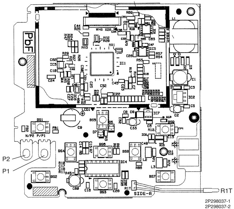
text_image
PbF C44 R25 WH8 X20 C34 R16 R26 R17 R29 R27 C62 IC3 C10 C24 R20 R20 C48 C31 C30 C29 C28 C27 R10 R11 R12 R13 R14 R15 R16 R17 R18 R19 R20 R21 R22 R23 R24 R25 R26 R27 R28 R29 R30 R31 R32 R33 R34 R35 R36 R37 R38 R39 R40 R41 R42 R43 R44 R45 R46 R47 R48 R49 R50 R51 R52 R53 R54 R55 C47 IC5 C26 IC1 C45 C25 C24 C23 C22 C21 C20 C19 C18 C17 C16 C15 R7 C14 R6 C13 R5 C12 R45- C11 R36- C10 R27- C9 R18- C8 D9- D8 C7- D7 C5- D6 C4- D5 C3- D4 C2- D3 C1- D2 C0- D1 C9- D0 C8- D9 C7- D8 C6- D7 C5- D6 C4- D5 C3- D4 C2- D3 C1- D2 C0- D1 C9- D0 C8- D9 C7- D8 C6- D7 C5- D6 C4- D5 C3- D4 C2- D3 C1- D2 C0- D1 C9- D0 C8- D9 C7- D8 C5- D7 C4- D6 C3- D5 C2- D4 C1- D3 C0- D2 C9- D1 C8- D0 C7- D9 C6- D8 C5- D7 C4- D6 C3- D5 C2- D4 C1- D3 C0- D2 C9- D1 C8- D0 C7- D9 C6- D8 C5- D7 C4- D6 C3- D5 C2- D4 C1- D3 C0- D2 C9- D1 C8- D0 C7- D9 C5- D8 C4- D7 C3- D6 C3- D5 C2- D4 C1- D3 C0- D2 C9- D1 C8- D0 C7- D9 C5- D8 C4- D7 C3- D6 C3- D5 C2- D4 C1- D3 C0- D2 C9- D1 C8- D0 C7- D9 C5- D8 C4- D7 C4- D6 C3- D5 C2- D4 C1- D3 C0- D2 C9- D1 C8- D0 C7- D9 C5- D8 C4- D7 C3- D6 C3- D5 C2- D4 C1- D3 C0- D2 C9- D1 C8- D0 C7- D9 C5- D8 C5- D7 C4- D6 C3- D5 C2- D4 C1- D3 C0- D2 C9- D1 C8- D0 C7- D9 C5- D8 C4- D7 C3- D6 C3- D5 C2- D4 C1- D3 C0- D2 C9- D1 C8- D0 C7- D9 C6- D8 C5- D7 C4- D6 C3- D5 C2- D4 C1- D3 C0- D2 C9- D1 C8- D0 C7- D9 C5-- C6B BSS BSS BSS BSS BSS BSS BSS BSS BSS BSS BSS BSS BSS BSS BSS BSS BSS BSS BSS BSS BSS BSS BSS BSS BSS BSS BSS BSS BSS BSS BSS BSS BSS BSS BSS BSS BSS BSS BSS BSS BSS BSS BSS BSS BSS BSS BSS BSS BSS BSS BCCB BCCB BCCB BCCB BCCB BCCB BCCB BCCB BCCB BCCB BCCB BCCB BCCB BCCB BCCB BCCB BCCB BCCB BCCB BCCB BCCB BCCB BCCB BCCB BCCB BCCB BCCB BCCB BCCB BCCB BCCB BCCB BCCB BCCB BCBC BCBC BCBC BCBC BCBC BCBC BCBC BCBC BCBC BCBC BCBC BCBC BCBC BCBC BCBC BCBC BCBC BCBC BCBC BCBC BCBC BCBC BCBC BCBC BCBC BCBC BCBC BCBC BCBC BCBC BCBC BCBC BCBC BCBC BCBC BCBC BCBC BCBC BCBC BCBC BCBC BCBC BCBC BCBC BCBC BCBC BCBC BCBC BCBC BCBC BCSCBC BCSCBC BCSCBC BCSCBC BCSCBC BCSCBC BCSCBC BCSCBC BCSCBC BCSCBC BCSCBC BCSCBC BCSCBC BCSCBC BCSCBC BCSCBC BCSCBC BCSCBC BCSCBC BCSCBC BCSCBC BCSCBC BCSCBC BCSCBC BCSCBC BCSCBC BCSCBC BCSCBC BCSCBC BCSCBC BCSCBC BCSCBC BCSCBC BCSCPCB CCDCB CCDCB CCDCB CCDCB CCDCB CCDCB CCDCB CCDCB CCDCB CCDCB CCDCB CCDCB CCDCB CCDCB CCDCB CCDCB CCDCB CCDCB CCDCB CCDCB CCDCB CCDCB CCDCB CCDCB CCDCB CCDCB CCDCB CCDCB CCDCB CCDCB CCDCB CCDCB CCDCB CCDCBB CCDCBB CCDCBB CCDCBB CCDCBB CCDCBB CCDCBB CCDCBB CCDCBB CCDCBB CCDCBB CCDCBB CCDCBB CCDCBB CCDCBB CCDCBB CCDCBB CCDCBB CCDCBB CCDCBB CCDCBB CCDCBB CCDCBB CCDCBB CCDCBB CCDCBB CCDCBB CCDCBB CCDCBB CCDCBB CCDCBB CCDCBB CCDCBB CCDCBB BBCC BBCC BBCC BBCC BBCC BBCC BBCC BBCC BBCC BBCC BBCC BBCC BBCC BBCC BBCC BBCC BBCC BBCC BBCC BBCC BBCC BBCC BBCC BBCC BBCC BBCC BBCC BBCC BBCC BBCC BBCC BBCC BBCC BBCC BBCC BBCC BBCC BBCC BBCC BBCC BBCC BBCC BBCC BBCC BBCC BBCC BBCC BBCC BBCC BBCC BBCCC BBCCC BBCCC BBCCC BBCCC BBCCC BBCCC BBCCC BBCCC BBCCC BBCCC BBCCC BBCCC BBCCC BBCCC BBCCC BBCCC BBCCC BBCCC BBCCC BBCCC BBCCC BBCCC BBCCC BBCCC BBCCC BBCCC BBCCC BBCCC BBCCC BBCCC BBCCC BBCCC BBCCC BBCCC BBCCC BBCCC BBCCC BBCCC BBCCC BBCCC BBCCC BBCCC BBCCC BBCCC BBCCC BBCCC BBCCC BBCCC BBCCC BBCCCCA A A A A A A A A A A A A A A A A A A A A A A A A A A A A A A A A A A A A A A A A A A A A A A A A A A A A A A A A A A A A A A A A A A A A A A A A A A A A A A A A A A A A A A A A A A A A A A A A A A A A T R1T 2P298037-1 2P298037-2Part 4
Function and Control
1. Indoor Unit Control (RA Models)....76
1.1 Temperature Control 76
1.2 Frequency Principle....76
1.3 Operation Starting Control....78
1.4 Airflow Direction Control....79
1.5 Fan Speed Control for Indoor Unit 82
1.6 RADIANT Operation....83
1.7 Program Dry Operation 85
1.8 Automatic Operation....86
1.9 Thermostat Control....87
1.10 NIGHT SET Mode 89
1.11 ECONO Operation 90
1.12 HOME LEAVE Operation 91
1.13 INTELLIGENT EYE Operation 92
1.14 2-Area INTELLIGENT EYE Operation .....93
1.15 Inverter POWERFUL Operation....95
1.16 Multi-Colored Indicator Lamp / TIMER Lamp 95
1.17 Other Functions....97
2. Indoor Unit Control (SA Models) 99
2.1 Drain Pump Control....99
2.2 Thermostat Sensor in Remote Controller 101
2.3 Freeze Prevention Control 103
2.4 Hot Start Control (In Heating Operation Only)....104
3. Function of Thermistor ....105
4. Control Specification ....107
4.1 Mode Hierarchy 107
4.2 Frequency Control....108
4.3 Controls at Mode Changing / Start-up....111
4.4 Discharge Pipe Temperature Control....112
4.5 Input Current Control....113
4.6 Freeze-up Protection Control 113
4.7 Heating Peak-cut Control 114
4.8 Outdoor Fan Control....115
4.9 Liquid Compression Protection Function....115
4.10 Defrost Control 116
4.11 Low Hz High Pressure Limit 117
4.12 Outdoor Electronic Expansion Valve Control 117
4.13 Malfunctions ...... 122
1. Indoor Unit Control (RA Models)
1.1 Temperature Control
Definitions of Temperatures
The definitions of temperatures are classified as following.
◆ Room temperature: temperature of lower part of the room
- Set temperature: temperature set by remote controller
◆ Room thermistor temperature: temperature detected by room temperature thermistor
- Target temperature: temperature determined by microcomputer
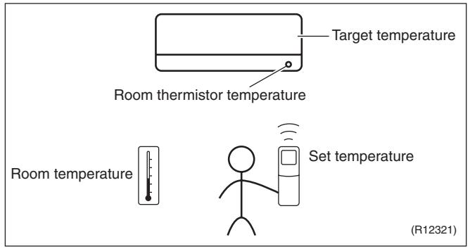
text_image
Target temperature Room thermistor temperature Room temperature Set temperature (R12321)★ The illustration is for wall mounted type as representative.
Temperature Control
The temperature of the room is detected by the room temperature thermistor. However, there is a difference between the “temperature detected by room temperature thermistor” and the “temperature of lower part of the room”, depending on the type of the indoor unit or installation condition. Practically, the temperature control is done by the “target temperature appropriately adjusted for the indoor unit” and the “temperature detected by room temperature thermistor”.
1.2 Frequency Principle
Main Control Parameters
The frequency of the compressor is controlled by the following 2 parameters:
■ The load condition of the operating indoor unit
■ The difference between the room thermistor temperature and the target temperature
Additional
The target frequency is adapted by additional parameters in the following cases:
Control
■ Frequency restrictions
■ Initial settings
■ Forced cooling operation
Inverter Principle
To regulate the capacity, a frequency control is needed. The inverter makes it possible to alter the rotation speed of the compressor. The following table explains the conversion principle:
| Phase | Description |
| 1 | The supplied AC power source is converted into the DC power source for the present. |
| 2 | The DC power source is reconverted into the three phase AC power source with variable frequency.■ When the frequency increases, the rotation speed of the compressor increases resulting in an increased refrigerant circulation. This leads to a higher amount of the heat exchange per unit.■ When the frequency decreases, the rotation speed of the compressor decreases resulting in a decreased refrigerant circulation. This leads to a lower amount of the heat exchange per unit. |
Drawing of Inverter
The following drawing shows a schematic view of the inverter principle:
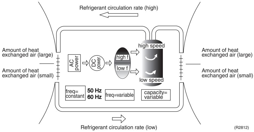
flowchart
graph TD
    A["Amount of heat exchanged air (large)"] --> B["AC power"]
    B --> C["DC power"]
    C --> D["high f"]
    C --> E["low f"]
    D --> F["high speed"]
    E --> G["low speed"]
    F --> H["Amount of heat exchanged air (large)"]
    G --> I["Amount of heat exchanged air (small)"]
    J["Refrigerant circulation rate (high)"] <--> K["Refrigerant circulation rate (low)"]
    L["Refrigerant circulation rate (low)"] <--> M["Refrigerant circulation rate (high)"]
    N["50 Hz"] --> O["freq=constant"]
    P["60 Hz"] --> Q["freq=variable"]
    R["capacity=variable"] --> S["capacity=variable"]
Inverter Features
The inverter provides the following features:
■ The regulating capacity can be changed according to the changes in the outdoor temperature and cooling / heating load.
■ Quick heating and quick cooling
The compressor rotational speed is increased when starting the heating (or cooling). This enables to reach the set temperature quickly.
■ Even during extreme cold weather, high capacity is achieved. It is maintained even when the outdoor temperature is 2^ C.
■ Comfortable air conditioning
A fine adjustment is integrated to keep the room temperature constant.
■ Energy saving heating and cooling
Once the set temperature is reached, the energy saving operation enables to maintain the room temperature at low power.
Frequency Limits
The following functions regulate the minimum and maximum frequency:
| Frequency | Functions |
| Low | ■ Four way valve operation compensation. Refer to page 111. |
| High | ■ Compressor protection function. Refer to page 112.■ Discharge pipe temperature control. Refer to page 112.■ Input current control. Refer to page 113.■ Freeze-up protection control. Refer to page 113.■ Heating peak-cut control. Refer to page 114.■ Defrost control. Refer to page 116. |
Forced Operation
Refer to page 405 for detail.
1.3 Operation Starting Control
Outline
Wall Mounted Type: FTXG Series
The system carries out the following control at the beginning to conduct every functional parts properly.
- Opening the front panel fully
- Output of the D signal after the front panel starts moving
- Opening the flap fully after the front panel opens fully
- Making the fan rotate when the flap passes over the fan-banned area
Control Flow
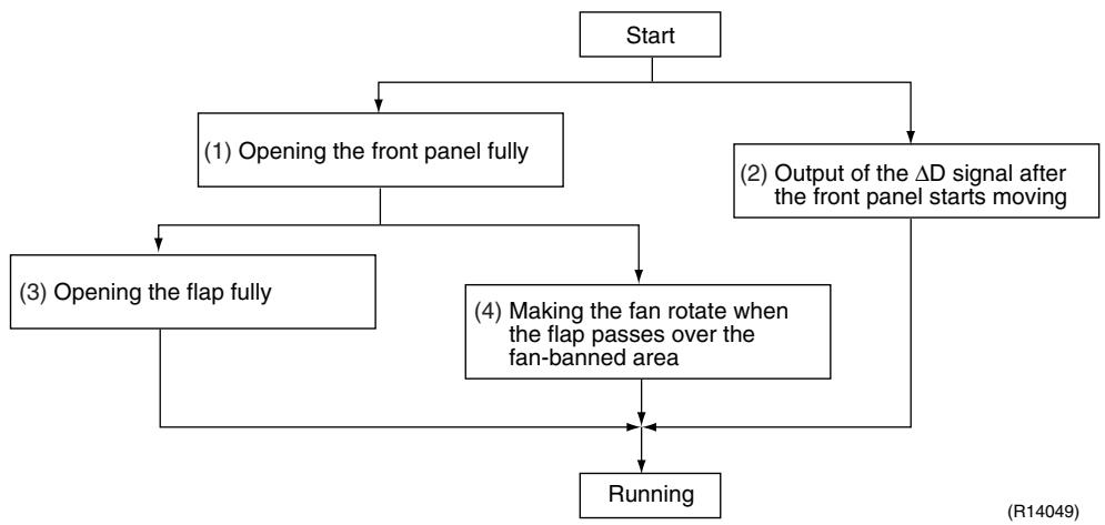
flowchart
graph TD
    A["Start"] --> B["(1) Opening the front panel fully"]
    A --> C["(2) Output of the ΔD signal after the front panel starts moving"]
    B --> D["(3) Opening the flap fully"]
    C --> E["(4) Making the fan rotate when the flap passes over the fan-banned area"]
    D --> F["Running"]
    E --> F
Timing Chart
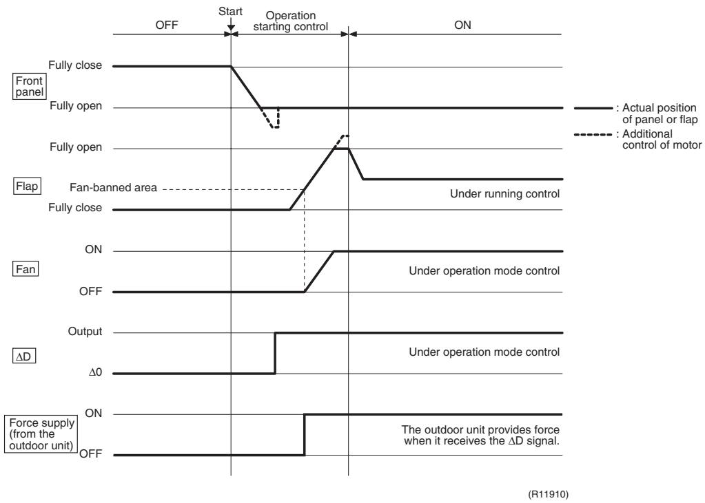
other
| Signal | Condition | Value | |-----------------|---------------------------|-------| | Left Panel | Fully close | ON | | Left Panel | Fully open | ON | | Left Panel | Fully open | ON | | Left Panel | Fan-banned area | ON | | Left Panel | Flap | ON | | Left Panel | Fan | ON | | Left Panel | Output | ON | | Left Panel | ΔD | ON | | Left Panel | Force supply (from the outdoor unit) | ON | | Left Panel | Power Supply (from the outdoor unit) | ON | | Right Panel | Actual position of panel or flap | ON | | Right Panel | Additional control of motor | ON | | Right Panel | Under running control | ON | | Right Panel | Under operation mode control | ON | | Right Panel | Under operation mode control | ON | | Right Panel | The outdoor unit provides force when it receives the ΔD signal. | ON | | Right Panel | The outdoor unit provides force when it receives the ΔD signal. | ON | | Right Panel | The outdoor unit provides force when it receives the ΔD signal. | ON | | Right Panel | The outdoor unit provides force when it receives the ΔD signal. | ON | | Right Panel | The outdoor unit provides force when it receives the ΔD signal. | ON | | Right Panel | The outdoor Unit provides force when it receives the ΔD signal. | ON | | Right Panel | The outdoor Unit provides force when it receives the ΔD signal. | ON | | Right Panel | The outdoor Unit provides force when it receives the ΔD signal. | ON | | Right Panel | The outdoor Unit provides force when it receives the ΔD signal. | ON | | Right Panel | The outdoor Unit provides force when it receives the ΔD signal. | OFF | | Right Panel | The outdoor Unit provides force when it receives the ΔD signal. | OFF | | Right Panel | The outdoor Unit provides force when it receives the ΔD signal. | OFF | | Right Panel | The outdoor Unit provides force when it receives the ΔD signal. | OFF | | Right Panel | The outdoor Unit provides force when it receives the ΔD signal. | OFF | | Right Panel | The outdoor Unit provides force (ΔD) | OFF | | Right Panel | The outdoor Unit provides force (ΔD) | OFF | | Right Panel | The outdoor Unit provides force (ΔD) | OFF | | Right Panel | The outdoor Unit provides force (ΔD) | OFF | | Right Panel | The outdoor Unit provides force (ΔD) | OFF | | Right Panel | The outdoor Unit provides force (ΔD) | OFF |1.4 Airflow Direction Control
Power-Airflow Dual Flaps
The large flap sends a large volume of air downward to the floor. The flap provides an optimum control in cooling, dry, and heating operation.
During cooling or dry operation, the flap retracts into the indoor unit. Then, cool air can be blown far and distributed all over the room.
During heating operation, the large flap directs airflow downward to spread the warm air to the entire room.
Wide-Angle Louvers
The louvers, made of elastic synthetic resin, provide a wide range of airflow that guarantees comfortable air distribution.
Auto-Swing
The following table explains the auto-swing process for cooling, dry, heating, and fan:
Wall Mounted Type
| Series | Vertical Swing (up and down) | Horizontal Swing (right and left) | |||
| Cooling / Dry | Heating | Fan | |||
| FTXG | 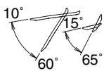 (R11662) (R11662) |  (R11664) (R11664) |  (R11663) (R11663) | — | |
| FTXS-KCTXS-K |  (R11256) (R11256) |  (R11257) (R11257) |  (R11256) (R11256) | — | |
| FTXS-J |  (R12182) (R12182) |  (R11402) (R11402) |  (R14208) (R14208) |  (R11404) (R11404) | |
| FTXS-G |  (R2814) (R2814) |  ~(R2815) ~(R2815) |  ~(R2813) ~(R2813) |  ~(R2816) ~(R2816) |  (R2817) (R2817) |
Floor Standing Type: FVXG Series
The swinging range of the flap is the same in any operation mode.
text_image
45° 25°(R14634)
Floor Standing Type: FVXS Series
| Vertical Swing (up and down) | ||
| Cooling / Dry | Heating | |
| Upward airflow limit OFF |  |  |
| (R6831) | (R6829) | |
| Upward airflow limit ON |  |  |
| (R6832) | (R6830) | |
Floor / Ceiling Suspended Dual Type
| Vertical Swing (up and down) | ||
| Cooling / Dry / Fan | Heating | |
| Ceiling |  (R2964) (R2964) |  (R2963) (R2963) |
| Floor |  (R2967) (R2967) | 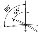 (R2966) (R2966) |
3-D Airflow
Wall Mounted Type: FTXS-J/G Series
Alternative repetition of vertical and horizontal swing motions enables uniform air-conditioning of the entire room. This function is effective for starting the air conditioner.
When the horizontal swing and vertical swing are both set to automatic operation, the airflow becomes 3-D airflow. The horizontal and vertical swing motion is altered and the airflow direction changes in the order shown in the following diagram.
(1): The vertical blades (louvers) move from the right to the left.
(2): The horizontal blades (flaps) move downward.
(3): The vertical blades (louvers) move from the left to the right.
(4): The horizontal blades (flaps) move upward.
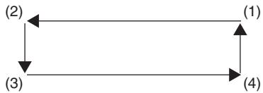
flowchart
graph TD
    A["(1)"] --> B["(2)"]
    B --> C["(3)"]
    C --> D["(4)"]
(R13554)
COMFORT AIRFLOW Operation
Wall Mounted Type
The vertical swing flap is controlled not to blow the air directly at the people in the room.
| Cooling / Dry | Heating |
| A—(R11665) | B (R12181) |
| A | B | |
| FTXG | 5^ | 75^ |
| FTXS-K, CTXS-K | 0^ | 50^ |
| FTXS-J | 8^ | 80^ |
| FTXS-G | 5^ | 55^ |
1.5 Fan Speed Control for Indoor Unit
Outline
Phase control and fan speed control contains 9 steps: LLL, LL, SL, L, ML, M, MH, H, and HH. The airflow rate can be automatically controlled depending on the difference between the room thermistor temperature and the target temperature. This is done through phase control and Hall IC control.

For more information about Hall IC, refer to the troubleshooting for fan motor on page 274, 277.
Automatic Fan Speed Control
In automatic fan speed operation, the step "SL" is not available.
| Wall Mounted Type Floor Standing Type | Floor / Ceiling Suspended Dual Type Duct Connected Type | |||
| Step | Cooling | Heating | Cooling | Heating |
| LLL |  |  |  |  |
| LL | ||||
| L | ||||
| ML | ||||
| M | ||||
| MH | ||||
| H | ||||
| HH (POWERFUL) | (R11681) | (R6834) | (R6833) | (R6834) |
= The airflow rate is automatically controlled within this range when the [FAN] setting button is set to automatic.
The following drawing explains the principle of fan speed control for cooling.
Wall Mounted Type, Floor Standing Type
Room thermistor temperature – target temperature
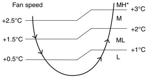
line
| Temperature | Fan speed | | ----------- | --------- | | +2.5°C | M | | +1.5°C | ML | | +0.5°C | L | | +3°C | MH* | | +2°C | M | | +1°C | ML |(R12317)
*The upper limit is M tap in 30 minutes from the operation start.
Floor / Ceiling Suspended Dual Type, Duct Connected Type
Fan speed
Room thermistor temperature – target temperature
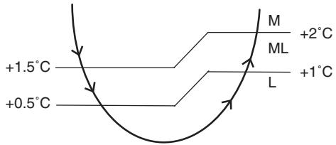
text_image
+1.5°C +0.5°C M ML L +2°C +1°C(R12390)
In heating operation, the fan speed is regulated according to the indoor heat exchanger temperature and the difference between the room thermistor temperature and the target temperature.

Note:
- During POWERFUL operation, the fan rotates at H tap + 40 \~ 90 rpm.
- The fan stops during defrost operation.
COMFORT
AIRFLOW
Operation
Wall Mounted Type
■ The fan speed is controlled automatically.
■ The latest command has the priority between POWERFUL and COMFORT AIRFLOW.
1.6 RADIANT Operation
Outline
Floor Standing Type: FVXG Series
The RADIANT operation has 2 operation modes.
♦ RADIANT 1: RADIANT operation with heating
♦ RADIANT 2: RADIANT operation only
1.6.1 Indoor Electronic Expansion Valve (Motor Operated Valve) Control
Initializing with Power ON
The indoor electronic expansion valve is initialized when turning on the power.
Opening Limit Control
Opening limit control limits the opening of the indoor electronic expansion valve in order to keep a specified range during RADIANT operation.
Starting Operation Control
Starting operation control opens the indoor electronic expansion valve to a certain degree when starting RADIANT operation. The indoor electronic expansion valve is kept open for a certain period.
Target Panel Temperature Control
When the starting operation control finishes, the target panel temperature control starts and adjusts the opening of the indoor electronic expansion valve to achieve the target panel temperature. The panel temperature is categorized into stop, dropping, keep, up, and return zones.
(The target panel temperature is 55^ C at maximum but it may be lower depending on the condition.)
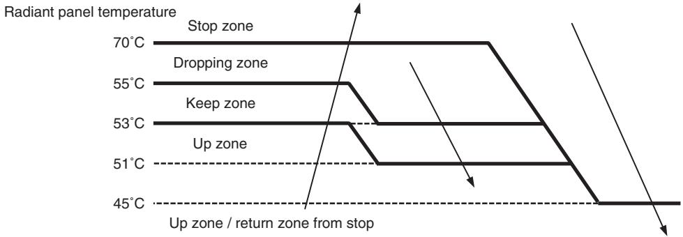
line
| Zone | Temperature | | ----------------- | ----------- | | Stop zone | 70°C | | Dropping zone | 55°C | | Keep zone | 53°C | | Up zone | 51°C | | Up zone / return zone from stop | 45°C |(R14636)
| Stop zone | Operation stops, the radiant panel temperature control is carried out. |
| Dropping zone | The opening of indoor electronic expansion valve decreases. |
| Keep zone | The opening of indoor electronic expansion valve is kept. |
| Up zone | The opening of indoor electronic expansion valve increases. |
| Return zone | Starting operation control is carried out. |
Operation Stop Control
In case operation stops during RADIANT operation (including thermostat off)
In case any of the following events occur while the indoor electronic expansion valve is open, the operation stop control makes the indoor electronic expansion valve close completely.
◆ Operation ON → OFF
♦ RADIANT 1 or RADIANT 2 is canceled.
- Thermostat off
♦ Defrost control
1.6.2 Indoor Unit Fan Control
The movement of the indoor unit fan is different whether in RADIANT 1 or RADIANT 2.
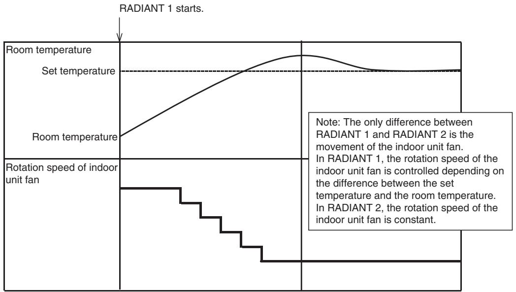
line
| Time Segment | Temperature Level | | ------------ | ----------------- | | Room temperature | Set temperature | | Room temperature | Room temperature | | Rotation speed of indoor unit fan | Indoor unit fan (step) | | Room temperature | Room temperature (constant) | Note: The only difference between RADIANT 1 and RADIANT 2 is the movement of the indoor unit fan. In RADIANT 1, the rotation speed of the indoor unit fan is controlled depending on the difference between the set temperature and the room temperature. In RADIANT 2, the rotation speed of the indoor unit fan is constant.(R14637)
1.6.3 RADIANT Operation and Optional Function
Some optional function cannot be used with RADIANT 1 or RADIANT 2 at the same time.
| Function | RADIANT 1 | RADIANT 2 |
| POWERFUL operation | available | not available |
| ECONO operation | not available | not available |
| OUTDOOR UNIT QUIET operation | not available | not available |
1.7 Program Dry Operation
Outline
Program dry operation removes humidity while preventing the room temperature from lowering. Since the microcomputer controls both the temperature and airflow rate, the temperature adjustment and [FAN] setting buttons are inoperable.
Detail
The microcomputer automatically sets the temperature and airflow rate. The difference between the room thermistor temperature at start-up and the target temperature is divided into two zones. Then, the unit operates an appropriate capacity for each zone to maintain the temperature and humidity at a comfortable level.
| Room thermistor temperature at start-up | Target temperature X | Thermostat OFF point Y | Thermostat ON point Z |
| 24°C or more | Room thermistor temperature at start-up | X - 2.5°C | X - 0.5°C or Y + 0.5°C (zone B) continues for 10 min. |
| 23.5°C | X - 2.0°C | X - 0.5°C or Y + 0.5°C (zone B) continues for 10 min. | |
| 18°C | |||
| 17.5°C | 18°C | X - 2.0°C | X - 0.5°C = 17.5°C or Y + 0.5°C (zone B) continues for 10 min. |
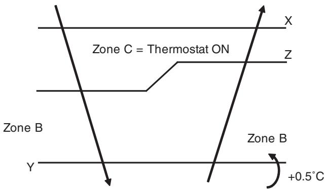
text_image
Zone C = Thermostat ON Zone B Zone B +0.5°CZone A = Thermostat OFF
(R11581)
1.8 Automatic Operation
Outline
Automatic Cooling / Heating Function
When the automatic operation is selected with the remote controller, the microcomputer automatically determines the operation mode as cooling or heating according to the room temperature and the set temperature at start-up.
The unit automatically switches the operation mode to maintain the room temperature at the set temperature.
Detail
Ts: set temperature (set by remote controller)
Tt: target temperature (determined by microcomputer)
Tr: room thermistor temperature (detected by room temperature thermistor)
C: correction value
-
The set temperature (Ts) determines the target temperature (Tt). (Ts = 18 \~ 30°C).
-
The target temperature (Tt) is calculated as;
$$ T t = T s + C $$
where C is the correction value.
$$ \mathrm{C} = 0 ^ {\circ} \mathrm{C} $$
- Thermostat ON/OFF point and operation mode switching point are as follows.
Tr means the room thermistor temperature.
(1) Heating → Cooling switching point:
$$ \mathrm{Tr} \geq \mathrm{Tt} + 3. 0 ^ {\circ} \mathrm{C} (\text { F T X G }, \text { F T X S - G }, \text { F V X G s e r i e s }) $$
$$ \mathrm{Tr} \geq \mathrm{Tt} + 2. 5 ^ {\circ} \mathrm{C} (\text { other models }) $$
(2) Cooling → Heating switching point:
$$ \mathrm{Tr} < \mathrm{Tt} - 2. 5 ^ {\circ} \mathrm{C} $$
(3) Thermostat ON/OFF point is the same as the ON/OFF point of cooling or heating operation.
- During initial operation
Tr ≥ Ts: Cooling operation
Tr < Ts: Heating operation
FTXG, FTXS-G, FVXG series
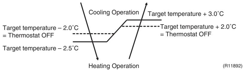
line
| Temperature Condition | Target Temperature (°C) | | --------------------------- | ------------------------ | | -2.0 | 2.0 | | -2.5 | 2.5 |Ex: When the target temperature is 25^ C
Cooling → 23°C: Thermostat OFF → 22°C: Switch to heating
Heating → 27°C: Thermostat OFF → 28°C: Switch to cooling
Other Models
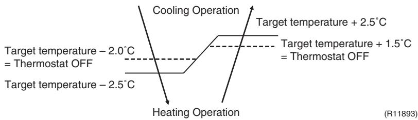
line
| Temperature Range | Target Temperature | | ----------------------- | ------------------ | | -2.0°C | 2.0°C | | 2.5°C | 2.5°C |Ex: When the target temperature is 25^ C
Cooling → 23°C: Thermostat OFF → 22°C: Switch to heating
Heating → 26.5°C: Thermostat OFF → 27.5°C: Switch to cooling
1.9 Thermostat Control
Thermostat control is based on the difference between the room thermistor temperature and the target temperature.
Thermostat OFF Condition
- The temperature difference is in the zone A.
Thermostat ON Condition
- The temperature difference returns to the zone C after being in the zone A.
- The system resumes from defrost control in any zones except A.
- The operation turns on in any zones except A.
The monitoring time has passed while the temperature difference is in the zone B. (Cooling / Dry : 10 minutes, Heating / Radiant : 10 seconds)
Wall Mounted Type, Floor Standing Type
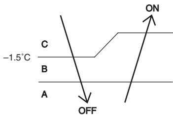
text_image
-1.5°C C B A OFF ONRoom thermistor temperature – target temperature
Cooling : -0.5°C
Dry : -0.5^
Cooling : -2.0°C
Dry : -2.5 \~ -2.0°C
(R12319)
Floor / Ceiling Suspended Dual Type, Duct Connected Type
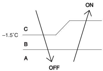
text_image
-1.5°C C B A OFF ONRoom thermistor temperature – target temperature
Cooling: -1.0^
Dry: -1.0^
Cooling : -2.0^
Dry: -2.5 -2.0^
(R12391)
Wall Mounted Type: FTXG, FTXS-G series
Floor Standing Type: FVXG series
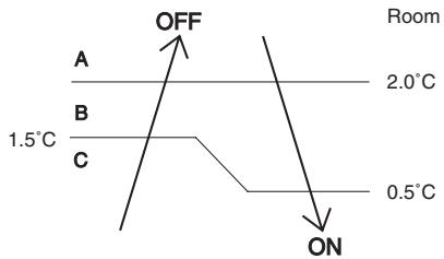
text_image
OFF A 2.0°C B 1.5°C C 0.5°C ONRoom thermistor temperature – target temperature
(R11894)
Wall Mounted Type: FTXS-K, CTXS-K, FTXS-J series
Floor Standing Type: FVXS series
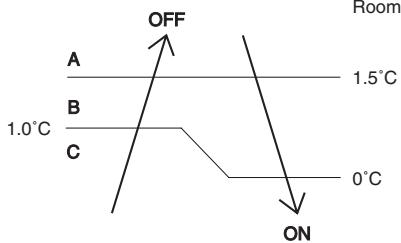
text_image
OFF A 1.0°C B C 1.5°C 0°C ON RoomRoom thermistor temperature – target temperature
(R12320)
Floor / Ceiling Suspended Dual Type, Duct Connected Type
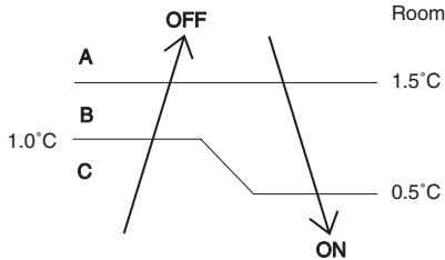
text_image
OFF A 1.0°C B C Room 1.5°C 0.5°C ONRoom thermistor temperature – target temperature
(R12392)

Refer to "Temperature Control" on page 76 for detail.
1.10 NIGHT SET Mode
Outline
When the OFF TIMER is set, the NIGHT SET Mode is automatically activated. The NIGHT SET Mode keeps the airflow rate setting.
Detail
The NIGHT SET Mode continues operation at the target temperature for the first one hour, then automatically raises the target temperature slightly in the case of cooling, or lowers it slightly in the case of heating. This prevents excessive cooling in summer and excessive heating in winter to ensure comfortable sleeping conditions, and also conserves electricity.
Ex: Wall Mounted Type, Floor Standing Type
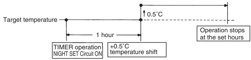
flowchart
graph LR
    A["Target temperature"] --> B["TIMER operation NIGHT SET CIRCUIT ON"]
    B --> C["+0.5°C temperature shift"]
    C --> D["Operation stops at the set hours"]
    D --> E["0.5°C"]
    style A fill:#f9f,stroke:#333
    style B fill:#ccf,stroke:#333
    style C fill:#cfc,stroke:#333
    style D fill:#fcc,stroke:#333
(R10870)
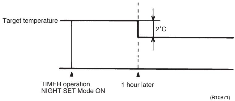
text_image
Target temperature 2°C TIMER operation NIGHT SET Mode ON 1 hour later (R10871)1.11 ECONO Operation
Wall Mounted Type, Floor Standing Type
The "ECONO operation" reduces the maximum operating current and the power consumption. This operation is particularly convenient for energy-saving-oriented users. It is also a major bonus for those whose breaker capacities do not allow the use of multiple electrical devices and air conditioners.
It is easily activated from the wireless remote controller by pushing the [ECONO] button.
■ When this function is activated, the maximum capacity also decreases.
■ ECONO operation can only be set when the unit is running. Pressing the [ON/OFF] button on the remote controller cancels the function.
■ ECONO operation is available when the unit is in AUTO, COOL, DRY, or HEAT operation and not available in RADIANT or FAN operation.
■ ECONO operation and POWERFUL operation cannot be used at the same time. The latest command has the priority.
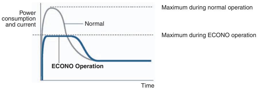
line
| Time Segment | Power Consumption and Current | ECONO Operation | | ------------------------- | ------------------------------ | --------------- | | Normal | Peak | Low | | ECONO Operation | High | Low |(R9288)
1.12 HOME LEAVE Operation
Outline
Floor / Ceiling Suspended Dual Type, Duct Connected Type
HOME LEAVE operation is a function that allows you to record your favorite set temperature and airflow rate. You can start your favorite operation mode simply by pressing the [HOME LEAVE] button on the remote controller.
Detail
1. Start of Function
The function starts when the [HOME LEAVE] button is pressed in cooling mode, heating mode (including POWERFUL operation), or while the operation is stopped. If this button is pressed in POWERFUL operation, the POWERFUL operation is canceled and this function becomes effective.
■ The [HOME LEAVE] button is ineffective in dry mode and fan mode.
2. Details of Function
A mark representing HOME LEAVE is indicated on the display of the remote controller. The indoor unit is operated according to the set temperature and airflow rate for HOME LEAVE which were pre-set in the memory of the remote controller.
The LED (red) of indoor unit representing HOME LEAVE lights up. (It goes out when the operation is stopped.)
3. End of Function
The function ends when the [HOME LEAVE] button is pressed again during HOME LEAVE operation or when the [POWERFUL] button is pressed.
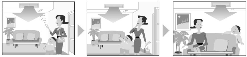
text_image
Illustration showing three sequential home improvement scenarios: lighting, living room setup, and living room setup with furniture.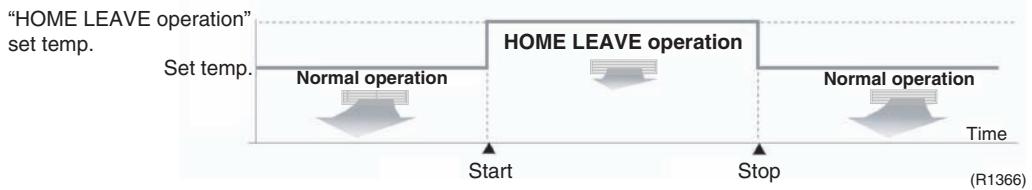
flowchart
graph LR
    A["Start"] --> B["Normal operation"]
    B --> C["Stop"]
    C --> D["Normal operation"]
    D --> E["Time"]
    style A fill:#f9f,stroke:#333
    style B fill:#ccf,stroke:#333
    style C fill:#cfc,stroke:#333
    style D fill:#fcc,stroke:#333
    style E fill:#cff,stroke:#333
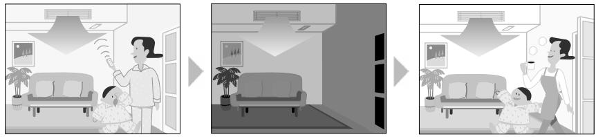
natural_image
Three-panel illustration showing a woman and child in a living room with ceiling lights, connected by arrows to a baby (no text or symbols)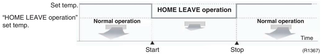
flowchart
graph LR
    A["Start"] --> B["Stop"]
    B --> C["Normal operation"]
    C --> D["Normal operation"]
    D --> E["Time"]
    style A fill:#f9f,stroke:#333
    style B fill:#ccf,stroke:#333
    style C fill:#cfc,stroke:#333
    style D fill:#fcc,stroke:#333
    style E fill:#cff,stroke:#333
Others
The set temperature and airflow rate are memorized in the remote controller. When the remote controller is reset due to replacement of battery, it is necessary to set the temperature and airflow rate again for HOME LEAVE operation.
1.13 INTELLIGENT EYE Operation
Outline
Wall Mounted Type: FTXG, FTXS-K, CTXS-K, FTXS-G Series
This function detects the existence of humans in the room with a human motion sensor (INTELLIGENT EYE) and reduces the capacity when there is nobody in the room in order to save electricity.
Detail
- Detection method by INTELLIGENT EYE
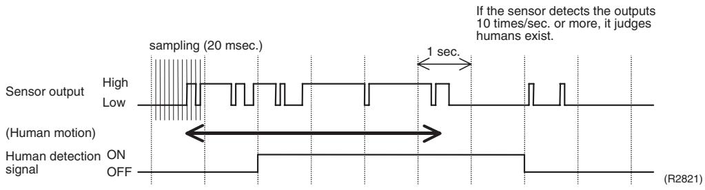
other
| Signal Type | Description | | ----------------- | -------------------------------- | | Sensor output | High / Low | | Human motion | On/OFF | | If sensor detects | 10 times/sec. or more, humans exist. |■ The sensor detects human motion by receiving infrared rays and displays the pulse wave output.
A microcomputer in an indoor unit carries out a sampling every 20 msec. and if it detects 10 cycles of the wave in 1 second in total (corresponding to 20 msec. × 10 = 200 msec.), it judges humans are in the room as the motion signal is ON.
- The motions (for example: in cooling)
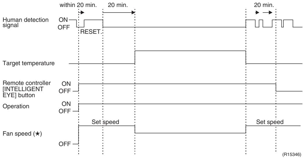
other
| Signal Type | Time | | ---------------------------- | ------------- | | Human detection signal | within 20 min. | | Target temperature | 20 min. | | Remote controller [INTELLIGENT EYE] button | 20 min. | | Operation | 20 min. | | Fan speed (★) | 20 min. |■ When the microcomputer does not have a signal from the sensor in 20 minutes, it judges that nobody is in the room and operates the unit at a temperature shifted from the target temperature. (Cooling / Dry : 1 \~ 2°C higher, Heating : 2°C lower, Auto : according to the operation mode at that time.)
★ In FAN operation, the fan speed is reduced by 60 rpm.
Others
■ For dry operation, you cannot set the temperature with a remote controller, but the target temperature is shifted internally.
1.14 2-Area INTELLIGENT EYE Operation
Outline
Wall Mounted Type: FTXS-J Series
The following functions can be performed by a motion sensor (INTELLIGENT EYE).
- Reduction of the capacity when there is nobody in the room in order to save electricity (energy saving operation)
- Dividing the room into plural areas and detecting existence of humans in each area. Moving the airflow direction to the area with no human automatically to avoid direct airflow on humans.
Detail
1. Detection method of INTELLIGENT EYE

other
| Signal Type | Description | | ----------------------- | ------------------------------------- | | Sensor output | High sampling (20 msec) | | Detection signal from the sensor | ON OFF (Condition of 10 times or more output) | | Human motion | (Continue 3 sec.) | | Human detection signal | ON OFF (If the sensor detects the outputs 10 times/sec. or more, it judges humans exist.) | | If the sensor detects the outputs 10 times/sec. or more, it judges humans exist. | 1 sec | | If the detection signal (ON) | Continues 3 sec. or more, it judges humans exist. |This sensor detects human motion by receiving infrared rays and displays the pulse wave output.
■ The microcomputer in the indoor unit carries out a sampling every 20 msec. and if it detects 10 cycles of the wave in one second in total (corresponding to 20 msec.× 10 = 200 msec.), and when the ON signal continues 3 sec., it judges human is in the room as the motion signal is ON
■ 2-area INTELLIGENT EYE sensor is divided into 2 areas and detects humans in each area.
■ Image of 2-area INTELLIGENT EYE
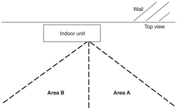
text_image
Indoor unit Area B Area A Wall Top view- A microcomputer judges human existence by the sensor signal from each area A and B.
(R12276)
- Motions (for example: in cooling)
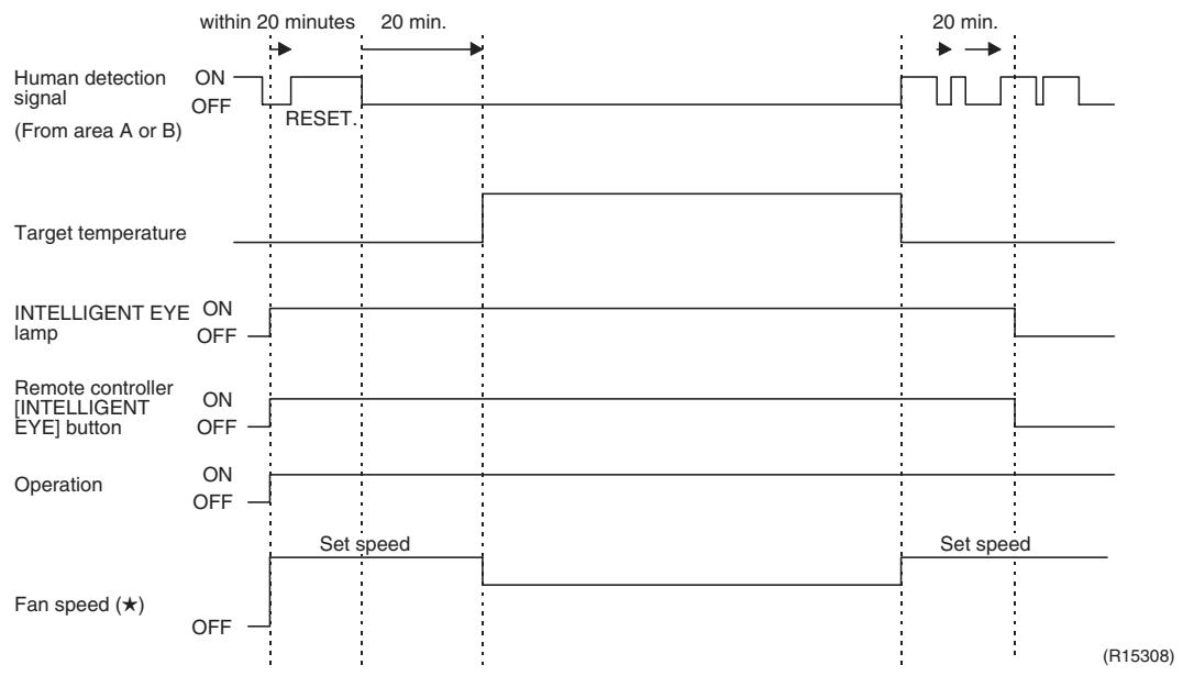
other
| Signal State | Timeframe | Value | | ------------ | --------- | ----- | | Human detection signal (From area A or B) | within 20 minutes | ON OFF | | Target temperature | within 20 minutes | RESET | | INTELLIGENT EYE lamp | within 20 minutes | ON OFF | | Remote controller [INTELLIGENT EYE] button | within 20 minutes | ON OFF | | Operation | within 20 minutes | ON OFF | | Fan speed (★) | within 20 minutes | ON OFF | | Target temperature | within 20 minutes | 20 min. | | Remote controller [INTELLIGENT EYE] button | within 20 minutes | 20 min. | | Operation | within 20 minutes | Set speed | | Fan speed (★) | within 20 minutes | Set speed | R15308■ When the microcomputer does not have a signal from the sensor in 20 minutes, it judges that nobody is in the room and operates the unit in temperature shifted from the target temperature. (Cooling / Dry : 2°C higher, Heating : 2°C lower, Auto : according to the operation mode at that time.)
★ In case of FAN operation, the fan speed reduces by 60 rpm.
3. Airflow direction in 2-area INTELLIGENT EYE operation
■ Detection method: The opposite area of detected area is set as the target direction.
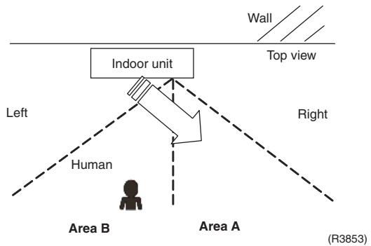
text_image
Wall Top view Indoor unit Left Right Human Area B Area A (R3853)- Detection signal ON in both area A and B: Shift the airflow direction to area B (left side)
- Detection signal ON in area A: Shift the airflow direction to area B (left side)
- Detection signal ON in area B: Shift the airflow direction to area A (right side)
- Detection signal OFF in both area A and B: No change
* When the detection signal is OFF for 20 minutes in both area A and B, the unit starts energy saving operation.
Others
■ For dry operation, you cannot set the temperature with remote controller, but internally the target temperature is shifted.
1.15 Inverter POWERFUL Operation
Outline
In order to exploit the cooling and heating capacity to full extent, operate the air conditioner by increasing the indoor fan rotating speed and the compressor frequency.
Detail
When the [POWERFUL] button is pressed, the fan speed and target temperature are converted to the following states for 20 minutes.
| Operation mode | Fan speed | Target temperature |
| COOL | H tap + A rpm | 18°C |
| DRY | Dry rotating speed + A rpm | Lowered by 2 ~ 2.5°C |
| HEAT / RADIANT 1 | H tap + A rpm | 30 ~ 32°C |
| FAN | H tap + A rpm | — |
| AUTO | Same as cooling / heating in POWERFUL operation | The target temperature is kept unchanged. |
A = 40 \~ 90 rpm (depending on the model)
Ex: POWERFUL operation in cooling
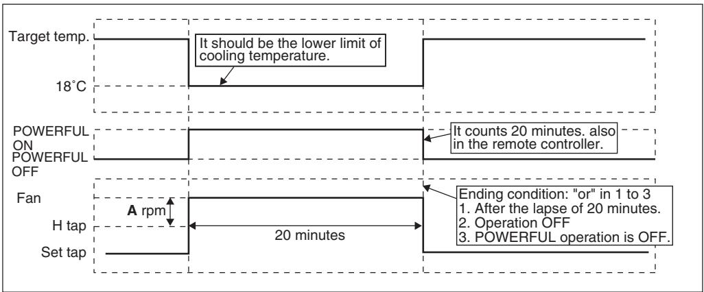
flowchart
graph TD
    A["Target temp."] --> B["18°C"]
    B --> C["It should be the lower limit of cooling temperature."]
    C --> D["POWERFUL ON POWERFUL OFF"]
    D --> E["It counts 20 minutes. also in the remote controller."]
    E --> F["Ending condition: "or" in 1 to 3"]
    F --> G["1. After the lapse of 20 minutes.<br>2. Operation OFF<br>3. POWERFUL operation is OFF."]
    F --> H["A rpm"]
    H --> I["H tap"]
    I --> J["20 minutes"]
    J --> K["Set tap"]
(R13571)

Note:
For Floor Standing Type: FVXG Series
POWERFUL operation is only available in RADIANT 1 (RADIANT operation with heating), it is not available in RADIANT 2 (RADIANT operation only).
1.16 Multi-Colored Indicator Lamp / TIMER Lamp
Features
Wall Mounted Type: FTXG Series
Current operation mode is displayed in color of the lamp of the indoor unit. Operating status can be monitored even in automatic operation in accordance with the actual operation mode.
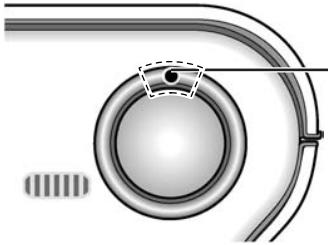
natural_image
Technical diagram of a mechanical component with concentric rings and a central hub (no text or symbols)Multi-colored indicator lamp / TIMER lamp
(R15294)
The lamp color changes according to the operation.
* AUTO ....Red / Blue
* DRY ....Green
* COOL......Blue
* HEAT ....Red
* FAN......White
* TIMER....Orange
Brightness Setting
The brightness of the multi-colored indicator lamp can be adjusted L (low), H (high), or OFF.
- Press the center of the [Temp] button and the [Mode] button at the same time.
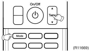
text_image
On/Off Timer Mode (R11669)SC is displayed on the LCD.
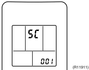
text_image
5C 001 (R11911)- Select L (light) with the [Temp] ▲ or ▼ button.
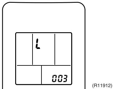
text_image
1 003 (R11912)- Press the [Mode] button to enter the brightness setting mode.
- Press the [Temp] ▲ or ▼ button to adjust the brightness of the multi-colored indicator lamp.
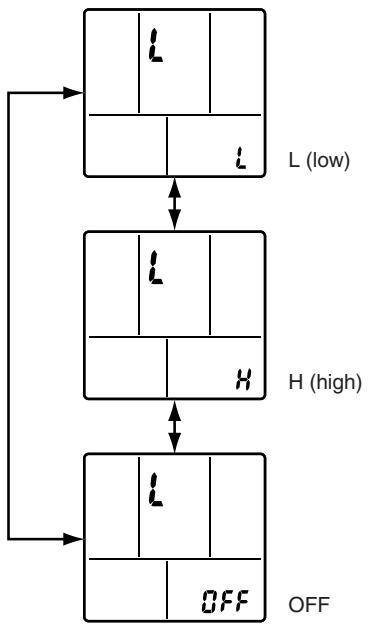
flowchart
graph TD
    A["Step 1: L (low)"] --> B["Step 2: H (high)"]
    B --> C["Step 3: OFF"]
    style A fill:#f9f,stroke:#333
    style B fill:#f9f,stroke:#333
    style C fill:#f9f,stroke:#333
(R11913)
- Press the [Mode] button for 5 seconds to exit from the brightness setting mode.
(When the remote controller is left untouched for 60 seconds, it returns to the normal mode also.)
1.17 Other Functions
1.17.1 Hot-Start Function
In order to prevent the cold air blast that normally comes when heating operation is started, the temperature of the indoor heat exchanger is detected, and the airflow is either stopped or made very weak thereby carrying out comfortable heating of the room.
* The cold air blast is also prevented using similar control when the defrosting operation is started or when the thermostat is turned ON.
1.17.2 Signal Receiving Sign
When the indoor unit receives a signal from the remote controller, the unit emits a signal receiving sound.
1.17.3 Indoor Unit [ON/OFF] Button
An [ON/OFF] button is provided on the display of the unit.
■ Press the [ON/OFF] button once to start operation. Press once again to stop it.
■ The [ON/OFF] button is useful when the remote controller is missing or the battery has run out.
■ The operation mode refers to the following table.
| Operation mode | Temperature setting | Airflow rate | |
| Cooling Only | COOL | 22°C | Automatic |
| Heat Pump | AUTO | 25°C | Automatic |
In the case of multi system operation, there are times when the unit does not activate with the [ON/OFF] button.
Ex: Wall mounted type FTXS-J series
![DAIKIN FVXM-F/FVXS-F - Indoor Unit [ON/OFF] Button - 1](/content/2020/11/206417/images/5d1cc5faf8529a11815799aceca6bfe91f6b8f4022e61c1133f0f0ecf313d355.jpg)
text_image
[ON/OFF] button (R8302)![DAIKIN FVXM-F/FVXS-F - Indoor Unit [ON/OFF] Button - 2](/content/2020/11/206417/images/d8c546523be9e818510f91bb01d0c9e64474dc6706b84c71a11cbfe3a6d77df2.jpg)
Note: When the [ON/OFF] button is pressed for 10 seconds or more, the forced operation is stopped.
1.17.4 Titanium Apatite Photocatalytic Air-Purifying Filter
This filter combines the Air-Purifying Filter and Titanium Apatite Photocatalytic Deodorizing Filter as a single highly effective filter. The filter traps microscopic particles, decomposes odors and even deactivates bacteria and viruses. It lasts for 3 years without replacement if washed about once every 6 months.
1.17.5 Photocatalytic Deodorizing Filter
The photocatalytic deodorizing filter powerfully decomposes odor of tobacco, pet, etc. The deodorizing power is regenerated simply by being exposed to the sunshine. It is recommended to dry the filter in the sun for about 6 hours (after vacuuming the filter) every 6 months.
1.17.6 Air-Purifying Filter
The air-purifying filter collects tobacco smoke, pollen, etc. with electrostatic agency.
This filter includes a deodorizing active carbon filter that removes minute particles of odor.
Replace the air-purifying filter every 3 months.
1.17.7 Auto-restart Function
If a power failure (including one for just a moment) occurs during the operation, the operation restarts automatically when the power is restored in the same condition as before the power failure.

Note: It takes 3 minutes to restart the operation because the 3-minute standby function is activated.
1.17.8 WEEKLY TIMER Operation
Up to 4 timer settings can be saved for each day of the week (up to 28 settings in total).
Those 3 items of “ON/OFF”, “temperature” and “time” can be set.

Refer to "WEEKLY TIMER Operation" on page 167, 208 for detail.
1.17.9 Brightness Setting of the Indoor Unit Display
Floor Standing Type: FVXG Series
Each time you press the [Brightness] button on the remote controller, the brightness of the indoor unit display changes to "high", "low", or "off".
Refer to the operation manual for details.
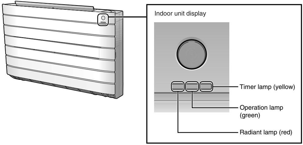
text_image
Indoor unit display Timer lamp (yellow) Operation lamp (green) Radiant lamp (red)(R14639)
2. Indoor Unit Control (SA Models)
2.1 Drain Pump Control
2.1.1 When the Float Switch is Tripped While the Cooling Thermostat is ON:
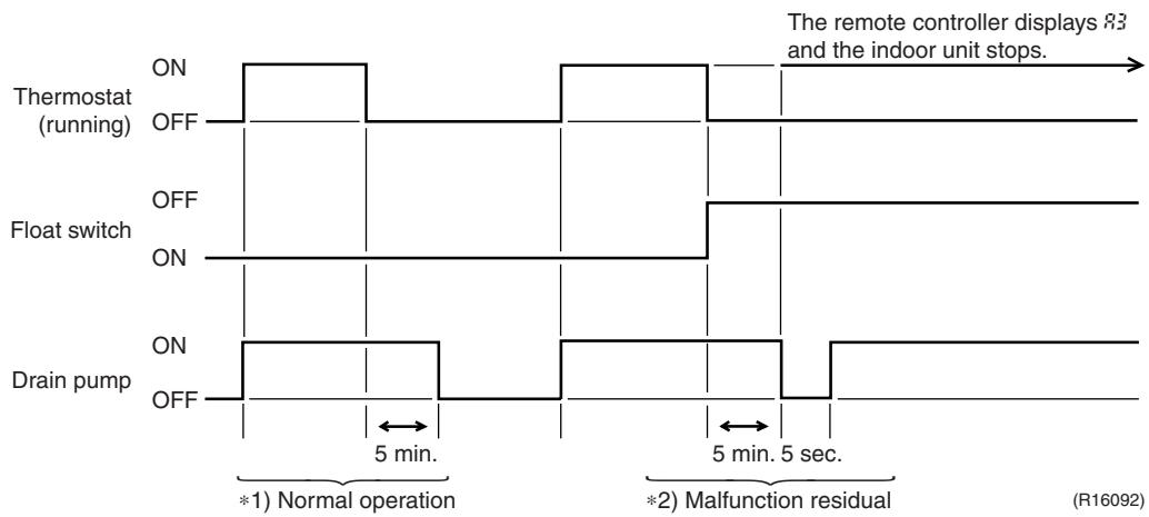
other
| Signal | Phase | Value | |-----------------|---------------------------|-------| | Thermostat (running) | ON | High | | Thermostat (running) | OFF | Low | | Float switch | ON | High | | Float switch | OFF | Low | | Drain pump | ON | High | | Drain pump | OFF | Low | | The remote controller | Normal operation | 83 | | The remote controller | Malfunction residual | 5 sec |*1. (Normal operation):
The purpose of residual operation is to completely drain any moisture adhering to the fin of the indoor heat exchanger when the thermostat goes off during cooling operation.
*2. (Malfunction residual):
The remote controller displays 83 and the air conditioner comes to an abnormal stop in 5 minutes if the float switch is turned OFF while the cooling thermostat is ON.
2.1.2 When the Float Switch is Tripped While the Cooling Thermostat is OFF:
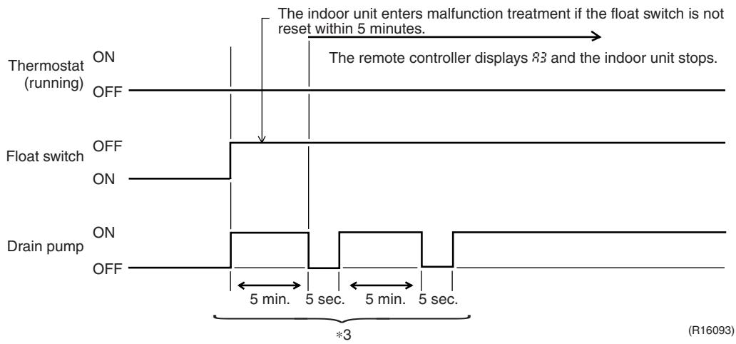
flowchart
graph TD
    A["Thermostat (running)"] --> B["ON"]
    B --> C["OFF"]
    C --> D["Float switch"]
    D --> E["ON"]
    E --> F["OFF"]
    F --> G["Drain pump"]
    G --> H["ON"]
    H --> I["OFF"]
    I --> J["5 min. 5 sec. 5 min. 5 sec."]
    J --> K["*3"]
    L["The indoor unit enters malfunction treatment if the float switch is not reset within 5 minutes."] --> M["The remote controller displays 83 and the indoor unit stops."]
*3. (Malfunction residual):
The remote controller displays 83 and the air conditioner comes to an abnormal stop if the float switch is turned OFF and not turned ON again within 5 minutes while the cooling thermostat is OFF.
2.1.3 When the Float Switch is Tripped During Heating Operation:
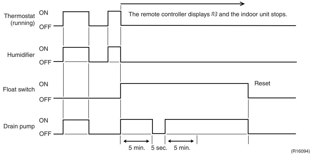
other
| Signal | ON | OFF | |-----------------|------|------| | Thermostat (running) | ON | OFF | | Humidifier | ON | OFF | | Float switch | ON | OFF | | Drain pump | ON | OFF |During heating operation, if the float switch is not reset even after the 5 minutes operation, 5 seconds stop, 5 minutes operation cycle ends, operation continues until the switch is reset.
2.1.4 When the Float Switch is Tripped and RF is Displayed on the Remote Controller:
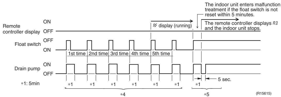
other
| Signal | Time Segment | |-----------------|----------------------| | ON | 1st time | | OFF | 2nd time | | Float switch | 3rd time | | ON | 4th time | | Off | 5th time | | Drain pump | 1st time | | ON | 2nd time | | OFF | 3rd time | | On | 4th time | | Off | 5th time | | *1: 5min | *1 | | *4 | *4 | | *5 | *5 |*4. (Malfunction residual):
If the float switch is tripped 5 times in succession, a drain malfunction is determined to have occurred. RF is then displayed as operation continues.
*5. (Malfunction residual):
The remote controller displays 83 and the air conditioner comes to an abnormal stop if the float switch is OFF for more than 5 minutes in the case of *4.
2.2 Thermostat Sensor in Remote Controller
Temperature is controlled by both the thermostat sensor in remote controller and air suction thermostat in the indoor unit. (This is however limited to when the field setting for the thermostat sensor in remote controller is set to "Use.")
Cooling
If there is a significant difference in the set temperature and the suction temperature, fine adjustment control is carried out using a body thermostat sensor, or using the sensor in the remote controller near the position of the user when the suction temperature is near the set temperature.
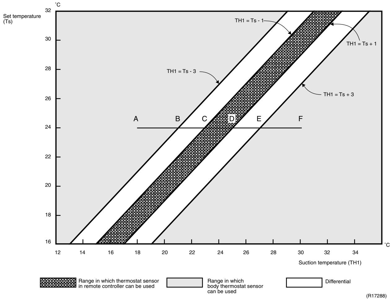
heatmap
| Suction temperature (TH1) | Set temperature (Ts) | Range in which thermostat sensor in remote controller can be used (°C) | | ------------------------ | -------------------- | ------------------------------------------------------------------- | | 12 | 16 | Not defined | | 14 | 18 | Not defined | | 16 | 20 | Not defined | | 18 | 22 | Not defined | | 20 | 24 | Not defined | | 22 | 26 | Not defined | | 24 | 28 | Not defined | | 26 | 30 | Not defined | | 28 | 32 | Not defined | | 30 | 30 | Not defined | | 32 | 28 | Not defined | | 34 | 26 | Not defined | | 36 | 24 | Not defined | | 38 | 22 | Not defined | | 40 | 20 | Not defined | | 42 | 18 | Not defined | | 44 | 16 | Not defined | The chart displays a diagonal band of contour lines representing different ranges of the parameter space used for a system. The legend indicates: 'Range in which thermostat sensor in remote controller can be used' (dark pattern), 'Range in which body thermostat sensor can be used' (light pattern), and 'Differential' (white line). The labels 'A', 'B', 'C', 'D', 'E', 'F' mark specific points along the diagonal bands.■ Assuming the set temperature in the figure above is 24^ , and the suction temperature has changed from 18^ to 30^ (A → F):
(This example also assumes there are several other air conditioners, and the suction temperature changes even when the thermostat sensor is off.)
Body thermostat sensor is used for temperatures from 18^ C to 23^ C (A → C).
Remote controller thermostat sensor is used for temperatures from 23^ C to 27^ C (C → E).
Body thermostat sensor is used for temperatures from 27^ C to 30^ C (E → F).
■ Assuming suction temperature has changed from 30^ C to 18^ C (F → A):
Body thermostat sensor is used for temperatures from 30^ C to 25^ C (F → D).
Remote controller thermostat sensor is used for temperatures from 25^ C to 21^ C (D → B).
Body thermostat sensor is used for temperatures from 21^ C to 18^ C (B → A).
Heating
When heating, the hot air rises to the top of the room, resulting in the temperature being lower near the floor where the occupants are. When controlling by body thermostat sensor only, the indoor unit may therefore be turned off by the thermostat before the lower part of the room reaches the set temperature. The temperature can be controlled so the lower part of the room where the occupants are does not become cold by widening the range in which thermostat sensor in remote controller can be used so that suction temperature is higher than the set temperature.
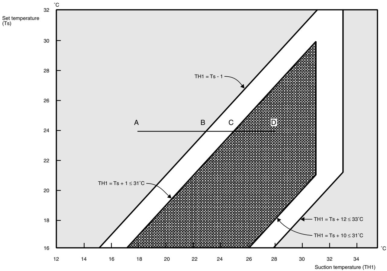
Range in which thermostat sensor in remote controller can be used
Range in which body thermostat sensor can be used
Differential
(R17289)
■ Assuming the set temperature in the figure above is 24^ , and the suction temperature has changed from 18^ to 28^ (A → D):
(This example also assumes there are several other air conditioners, and the suction temperature changes even when the thermostat sensor is off.)
Body thermostat sensor is used for temperatures from 18^ C to 25^ C (A → C).
Remote controller thermostat sensor is used for temperatures from 25^ C to 28^ C (C → D).
■ Assuming suction temperature has changed from 28^ C to 18^ C (D → A):
Remote controller thermostat sensor is used for temperatures from 28^ C to 23^ C (D → B). Body thermostat sensor is used for temperatures from 23^ C to 18^ C (B → A).
2.3 Freeze Prevention Control
When the temperature detected by liquid pipe thermistor (R2T) of the indoor heat exchanger drops too low, the unit enters freeze prevention control in accordance with the following conditions, and is also set in accordance with the conditions given below.
Conditions for starting: Temperature is -1^ or less for total of 40 min., or temperature is -5^ or less for total of 10 min.
Conditions for cancelling: Temperature is +7°C or more for 10 min. continuously
Ex: Case where temperature is -5^ or less for total of 10 min.
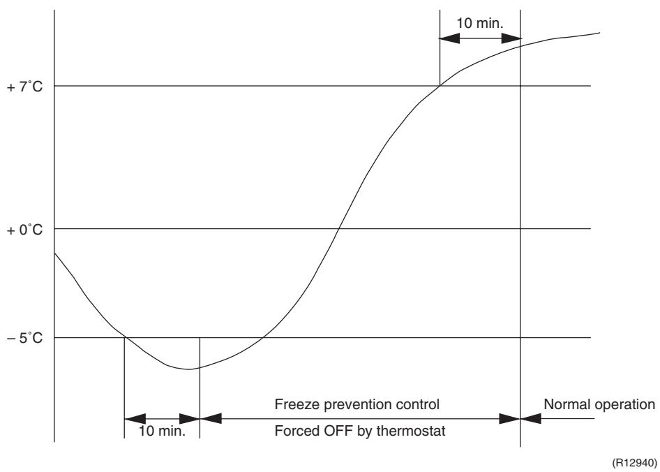
line
| Time | Temperature | | ------------- | ----------- | | 10 min. | -6°C | | Normal operation | +7°C |2.4 Hot Start Control (In Heating Operation Only)
Outline
At startup with thermostat ON or after the completion of defrosting in heating operation, the indoor unit fan is controlled to prevent cold air from blasting out and ensure startup capacity.
Detail
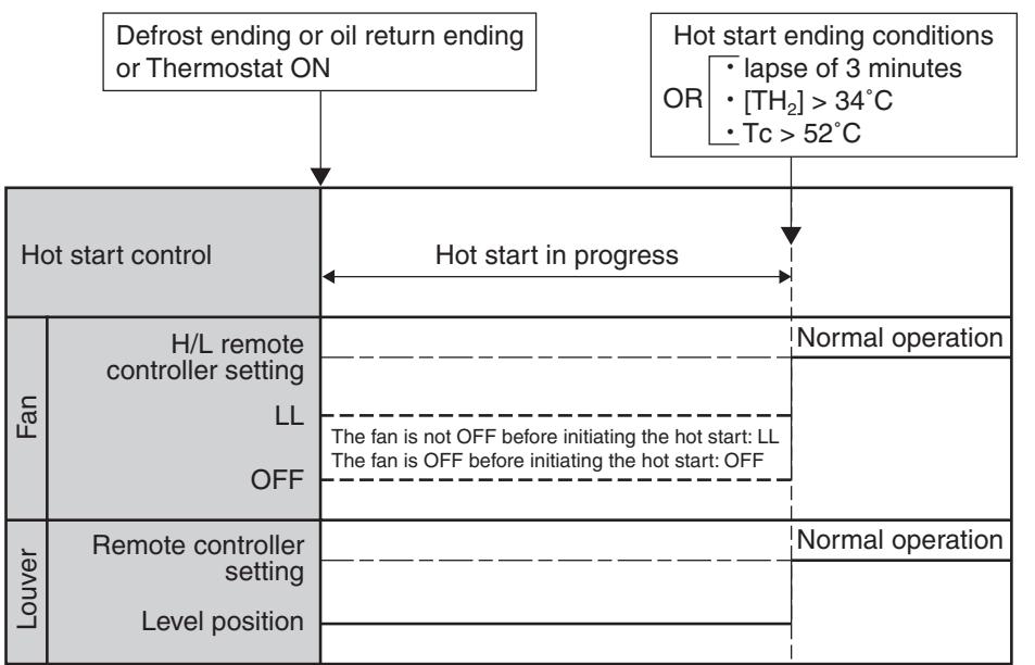
flowchart
graph TD
    A["Defrost ending or oil return ending or Thermostat ON"] --> B["Hot start control"]
    C["Hot start ending conditions OR { lapse of 3 minutes, [TH₂"] > 34°C, Tc > 52°C}] --> B
    B --> D["Hot start in progress"]
    D --> E["Fan"]
    E --> F["H/L remote controller setting LL OFF"]
    F --> G["Louver"]
    G --> H["Remote controller setting Level position"]
    H --> I["Normal operation"]
    I --> J["The fan is not OFF before initiating the hot start: LL The fan is OFF before initiating the hot start: OFF"]
    J --> K["Normal operation"]
(R15421)
TH_2 : Temperature ( ^ C) detected with the gas thermistor
TC : High pressure equivalent saturated temperature
3. Function of Thermistor
★ Illustrations are for 4-room models as representative and have 4 lines of indoor unit system (A \~ D). 3-room models have 3 lines (A \~ C) and 5-room models have 5 lines (A \~ E).
Cooling Only Model
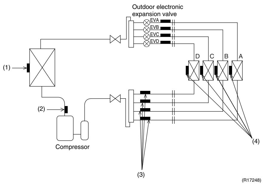
flowchart
graph TD
    A["Compressor"] --> B["(1)"]
    B --> C["Valve (2)"]
    C --> D["Valve (3)"]
    D --> E["Valve (4)"]
    E --> F["Outdoor electronic expansion valve"]
    F --> G["EVA"]
    F --> H["EVB"]
    F --> I["EVC"]
    F --> J["EVD"]
    G --> K["D"]
    H --> L["C"]
    I --> M["B"]
    J --> N["A"]
    style A fill:#f9f,stroke:#333
    style B fill:#ccf,stroke:#333
    style C fill:#cfc,stroke:#333
    style D fill:#fcc,stroke:#333
    style E fill:#cff,stroke:#333
    style F fill:#ffc,stroke:#333
    style G fill:#fff,stroke:#333
    style H fill:#fff,stroke:#333
    style I fill:#fff,stroke:#333
    style J fill:#fff,stroke:#333
    style K fill:#ccf,stroke:#333
    style L fill:#ccf,stroke:#333
    style M fill:#ccf,stroke:#333
    style N fill:#fff,stroke:#333
Heat Pump Model
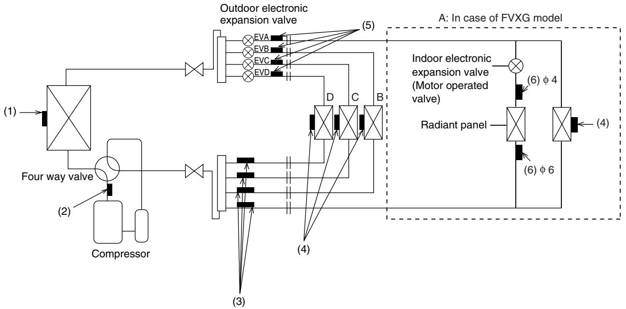
flowchart
graph TD
    A["Compressor"] --> B["Four way valve"]
    B --> C["Compressor"]
    C --> D["Outdoor electronic expansion valve"]
    D --> E["EVA"]
    D --> F["EVB"]
    D --> G["EVC"]
    D --> H["EVD"]
    E --> I["Indoor electronic expansion valve (Motor operated valve)"]
    F --> I
    G --> I
    H --> I
    I --> J["Radiant panel"]
    J --> K["(6) φ 4"]
    J --> L["(6) φ 6"]
    K --> M["A: In case of FVXG model"]
    L --> M
    M --> N["(4)"]
    style A fill:#f9f,stroke:#333
    style N fill:#ccf,stroke:#333
(R17159)
(1) Outdoor Heat Exchanger Thermistor
- The outdoor heat exchanger thermistor is used for controlling the target discharge pipe temperature. The system sets the target discharge pipe temperature according to the outdoor and indoor heat exchanger temperature, and controls the outdoor electronic expansion valve opening so that the target discharge pipe temperature can be obtained.
- In cooling operation, the outdoor heat exchanger thermistor is used for detecting the disconnection of the discharge pipe thermistor. When the discharge pipe temperature becomes lower than the outdoor heat exchanger temperature, the discharge pipe thermistor is judged as disconnected.
- In cooling operation, the outdoor heat exchanger thermistor is used for high pressure protection.
| (2) Discharge Pipe Thermistor | 1. The discharge pipe thermistor is used for controlling discharge pipe temperature. If the discharge pipe temperature (used in place of the inner temperature of the compressor) rises abnormally, the operating frequency becomes lower or the operation halts.2. The discharge pipe thermistor is used for detecting disconnection of the discharge pipe thermistor. |
| (3) Gas Pipe Thermistor | 1. In cooling operation, the gas pipe thermistor is used for gas pipe isothermal control. The system controls outdoor electronic expansion valve opening so that the gas pipe temperature in each room becomes equal. |
| (4) Indoor Heat Exchanger Thermistor | 1. The indoor heat exchanger thermistor is used for controlling the target discharge pipe temperature. The system sets the target discharge pipe temperature according to the outdoor and indoor heat exchanger temperature, and controls the outdoor electronic expansion valve opening so that the target discharge pipe temperature can be obtained.2. In cooling operation, the indoor heat exchanger thermistor is used for freeze-up protection control. If the indoor heat exchanger temperature drops abnormally, the operating frequency becomes lower or the operation halts.3. In cooling operation, the indoor heat exchanger thermistor is used for anti-icing function. If any of the following conditions are met in the room where operation halts, it is assumed as icing.The conditions are Tc -1^ C Ta - Tc 10^ C where Ta is the room temperature and Tc is the indoor heat exchanger temperature.4. In heating operation, the indoor heat exchanger thermistor is used for heating peak-cut control. If the indoor heat exchanger temperature rises abnormally, the operating frequency becomes lower or the operation halts.5. In heating operation, the indoor heat exchanger thermistor is used for detecting the disconnection of the discharge pipe thermistor. When the discharge pipe temperature becomes lower than the maximum indoor heat exchanger temperature, the discharge pipe thermistor is judged as disconnected.6. When only one indoor unit is operating, the indoor heat exchanger thermistor is used for subcooling control. The actual subcool is calculated with the liquid pipe temperature and the indoor heat exchanger temperature. The system controls the outdoor electronic expansion valve openings to obtain the target subcool.7. The indoor heat exchanger thermistor is used for wiring error check function. The refrigerant flows in order from the port A to detect the indoor heat exchanger temperature one by one, and then wiring and piping can be checked. |
| (5) Liquid Pipe Thermistor | 1. When only one indoor unit is in heating, the liquid pipe thermistor is used for subcooling control. The actual subcool is calculated with the liquid pipe temperature and the maximum indoor heat exchanger temperature. The system controls the outdoor electronic expansion valve openings to obtain the target subcool.2. In heating operation, the liquid pipe thermistor is used for liquid pipes isothermal control. The system controls the outdoor electronic expansion valve opening so that the liquid pipe temperatures in each room becomes equal. |
| (6) Radiant Panel Thermistors | 1. The radiant panel thermistors are used for calculating radiant panel surface temperature. Due to structural and manufactural restrictions, the radiant panel surface temperature cannot be controlled directly with a thermistor. Thermistors are mounted on the radiant panel piping in order to calculate the radiant panel surface temperature.The indoor electronic expansion valve is controlled according to the radiant panel surface temperature.2. The radiant panel thermistors are used for detecting malfunction of the indoor electronic expansion valve. |
4. Control Specification
4.1 Mode Hierarchy
Outline
There are 3 modes; normal operation mode, forced operation mode, and power transistor test mode for installation and servicing.
Detail
Cooling Only Model
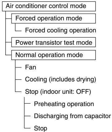
flowchart
graph TD
    A["Air conditioner control mode"] --> B["Forced operation mode"]
    B --> C["Forced cooling operation"]
    A --> D["Power transistor test mode"]
    A --> E["Normal operation mode"]
    E --> F["Fan"]
    E --> G["Cooling (includes drying)"]
    E --> H["Stop (indoor unit: OFF)"]
    H --> I["Preheating operation"]
    H --> J["Discharging from capacitor"]
    H --> K["Stop"]
(R14428)
Heat Pump Model
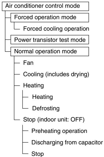
flowchart
graph TD
    A["Air conditioner control mode"] --> B["Forced operation mode"]
    A --> C["Forced cooling operation"]
    A --> D["Power transistor test mode"]
    A --> E["Normal operation mode"]
    E --> F["Fan"]
    E --> G["Cooling (includes drying)"]
    E --> H["Heating"]
    H --> I["Heating"]
    H --> J["Defrosting"]
    E --> K["Stop (indoor unit: OFF)"]
    K --> L["Preheating operation"]
    K --> M["Discharging from capacitor"]
    K --> N["Stop"]
(R14248)

Note:
■ Unless specified otherwise, a dry operation command is regarded as cooling operation and a radiant operation command is regarded as heating operation.
- Indoor fan operation cannot be made in multiple indoor units. (A forced fan command is made during forced cooling operation.)
Determine Operation Mode
The system judges the operation mode command which is set by each room in accordance with the procedure, and determines the operation mode of the system.
The following procedure is taken when the modes conflict with each other.
*1. The system follows the mode which is set first. (First-push, first-set)
*2. For the rooms where the different mode is set, standby mode is activated. (The operation lamp blinks.)
4.2 Frequency Control
Outline
Frequency that corresponds to each room's capacity is determined according to the difference between the target temperature and the temperature of each room.
The function is explained as follows.
- How to determine frequency
- Frequency command from an indoor unit (Difference between a room thermistor temperature and the target temperature)
- Frequency command from an indoor unit (The ranked capacity of the operating room)
- Frequency initial setting
- PI control
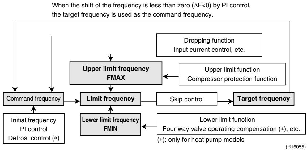
flowchart
graph TD
    A["Command frequency"] --> B["Limit frequency"]
    B --> C["Skip control"]
    C --> D["Target frequency"]
    E["Upper limit function FMAX"] --> B
    F["Dropping function Input current control, etc."] --> A
    G["Lower limit function Four way valve operating compensation (*), etc. (*) : only for heat pump models"] --> C
    H["Initial frequency PI control Defrost control (*)"] --> B
    I["Upper limit function Compressor protection function"] --> C
    J["Lower limit frequency FMIN"] --> B
Detail
How to Determine Frequency
The compressor's frequency is determined by taking the following steps.
For Cooling Only Model
1. Determine command frequency
◆ Command frequency is determined in the following order of priority.
1. Forced cooling
2. Indoor frequency command
2. Determine upper limit frequency
The minimum value is set as the upper limit frequency among the frequency upper limits of the following functions:
Compressor protection, input current, discharge pipe temperature, low Hz high pressure limit, freeze-up protection.
3. Determine lower limit frequency
The maximum value is set as lower limit frequency among the frequency lower limits of the following functions:
Draft prevention, pressure difference upkeep.
4. Determine prohibited frequency
- There is a certain prohibited frequency such as a power supply frequency.
For Heat Pump Model
1. Determine command frequency
- Command frequency is determined in the following order of priority.
- Limiting defrost control time
- Forced cooling / heating
- Indoor frequency command
2. Determine upper limit frequency
The minimum value is set as upper limit frequency among the frequency upper limits of the following functions:
Compressor protection, input current, discharge pipe temperature, low Hz high pressure limit, heating peak-cut, freeze-up protection, defrost.
3. Determine lower limit frequency
The maximum value is set as the lower limit frequency among the frequency lower limits of the following functions:
Four way valve operation compensation, draft prevention, pressure difference upkeep.
4. Determine prohibited frequency
- There is a certain prohibited frequency such as a power supply frequency.
Indoor Frequency Command ( D signal)
The difference between a room thermistor temperature and the target temperature is taken as the “ D signal” and is used for frequency command.
| Temperature difference (°C) | ΔD signal | Temperature difference (°C) | ΔD signal | Temperature difference (°C) | ΔD signal | Temperature difference (°C) | ΔD signal |
| -2.0 | *Th OFF | 0 | 4 | 2.0 | 8 | 4.0 | C |
| -1.5 | 1 | 0.5 | 5 | 2.5 | 9 | 4.5 | D |
| -1.0 | 2 | 1.0 | 6 | 3.0 | A | 5.0 | E |
| -0.5 | 3 | 1.5 | 7 | 3.5 | B | 5.5 | F |
Values depend on the type of indoor unit.
*Th OFF = Thermostat OFF
Indoor Unit Capacity (S value)
The capacity of the indoor unit is a “S” value and is used for frequency command.
| Ex: | Capacity | S value | Capacity | S value |
| 2.5 kW | 25 | 5.0 kW | 50 | |
| 3.5 kW | 35 | 6.0 kW | 60 |
Frequency Initial Setting
When starting the compressor, or when conditions are varied due to the change of the operating room, the frequency must be initialized according to the total of a maximum D value of each room and a total value of Q ( Q ) of the operating room (the room in which the thermos is set to ON).
Q value: Indoor unit output determined from indoor unit volume, airflow rate and other factors.
PI Control (Determine Frequency Up / Down by D Signal)
1. P control
A total of the D value is calculated in each sampling time (20 seconds), and the frequency is adjusted according to its difference from the frequency previously calculated.
2. I control
If the operating frequency is not change more than a certain fixed time, the frequency is adjusted according to the D value.
When the D value is low, the frequency is lowered.
When the D value is high, the frequency is increased.
3. Limit of frequency increasing range
When the difference between input current and input current dropping value is less than 1.5 A, the frequency increasing range must be limited.
4. Frequency management when other controls are functioning
- When each frequency is dropping;
Frequency management is carried out only when the frequency drops. - For limiting lower limit
Frequency management is carried out only when the frequency rises.
5. Upper and lower limit of frequency by PI control
The frequency upper and lower limits are set according to the total of S values. When the indoor unit quiet operation commands come from more than one room or when the outdoor unit quiet operation commands come from all the rooms, the upper limit frequency is lower than the usual setting.
4.3 Controls at Mode Changing / Start-up
4.3.1 Preheating Operation
| Outline | The inverter operation in open phase starts with the conditions of the preheating command from the outdoor unit. |
| Detail | ON ConditionWhen the outdoor temperature is below 10.5°C, the inverter operation in open phase starts.OFF ConditionWhen the outdoor temperature is higher than 12°C, the inverter operation in open phase stops. |
4.3.2 Four Way Valve Switching
| Outline | In heating operation, current is conducted, and in cooling and defrosting operation, current is not conducted. In order to eliminate the switching sound, as the four way valve coil switches from ON to OFF when the heating is stopped, the OFF delay switch of the four way valve is carried out. |
| Detail | OFF delay switch of four way valve:The four way valve coil is energized for 150 seconds after the operation is stopped. |
4.3.3 Four Way Valve Operation Compensation
| Outline | At the beginning of the operation as the four way valve is switched, the pressure difference to activate the four way valve is acquired by having output frequency which is more than a certain fixed frequency, for a certain fixed time. |
Detail Starting Conditions
- When starting the compressor for heating
- When the operation mode changes from the previous time
- When starting the compressor for defrosting
- When starting the compressor for the first time after resetting with the power ON. The lower limit of frequency keeps A Hz for 70 seconds with any conditions 1 through 4 above.
| A (Hz) | |
| 40/50/52/58 class | 48 |
| 68/75 class | 40 |
| 80/90 class | 28 |
4.3.4 3-Minute Standby
Turning on the compressor is prohibited for 3 minutes after turning off. (Except when defrosting.)
4.3.5 Compressor Protection Function
When turning the compressor from OFF to ON, the upper limit of frequency is set as follows. (The function is not used when defrosting.)
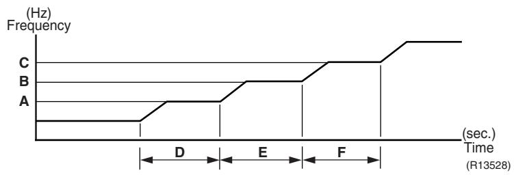
line
| Time (sec.) | Frequency (Hz) | |-------------|----------------| | 0 | 0 | | D | 0 | | E | 0 | | F | 0 | | Final | 0 || 40/50/52/58 class | 68/75/80/90 class | |
| A (Hz) | 55 | 55 |
| B (Hz) | 70 | 65 |
| C (Hz) | 85 | 80 |
| D (seconds) | 150 ~ 240 | 120 |
| E (seconds) | 180 | 200 |
| F (seconds) | 300 | 470 |
4.4 Discharge Pipe Temperature Control
Outline
The discharge pipe temperature is used as the internal temperature of the compressor. If the discharge pipe temperature rises above a certain level, the upper limit of frequency is set to keep the discharge pipe temperature from rising further.
Detail
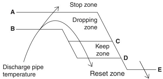
flowchart
graph TD
    A["Stop zone"] --> B["Dropping zone"]
    B --> C["Keep zone"]
    C --> D["Reset zone"]
    D --> E["E"]
    style A fill:#f9f,stroke:#333
    style B fill:#f9f,stroke:#333
    style C fill:#ccf,stroke:#333
    style D fill:#ccf,stroke:#333
    style E fill:#fff,stroke:#333
(R14266)
| 40/50/52/58 class | 68/75/80/90 class | |
| A (°C) | 110 | 120 |
| B (°C) | 103 | 111 |
| C (°C) | 102 | 109 |
| D (°C) | 100 | 107 |
| E (°C) | 95 | 107 |
| Zone | Control |
| Stop zone | When the temperature reaches the stop zone, the compressor stops. |
| Dropping zone | The upper limit of frequency decreases. |
| Keep zone | The upper limit of frequency is kept. |
| Reset zone | The upper limit of frequency is canceled. |
4.5 Input Current Control
Outline
An input current is detected by the CT while the compressor is running, and the frequency upper limit is set from the input current.
In case of heat pump models, this control which is the upper limit control of the frequency takes priority over the lower limit control of four way valve operation compensation.
Detail
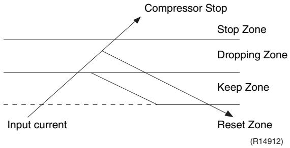
flowchart
graph TD
    A["Input current"] --> B["Stop Zone"]
    A --> C["Dropping Zone"]
    A --> D["Keep Zone"]
    A --> E["Reset Zone"]
    B --> F["Compressor Stop"]
    C --> F
    D --> F
    E --> F
Frequency control in each zone
Stop zone
- After 2.5 seconds in this zone, the compressor is stopped.
Dropping zone
- The upper limit of the compressor frequency is defined as operation frequency – 2 Hz.
- After this, the output frequency is lowered by 2 Hz every second until it reaches the keep zone.
Keep zone
- The present maximum frequency goes on.
Reset zone
- Limit of the frequency is canceled.
Limitation of current dropping and stop value according to the outdoor temperature
- The current drops when outdoor temperature becomes higher than a certain level (depending on the model).
4.6 Freeze-up Protection Control
Outline
During cooling operation, the signals sent from the indoor unit control the operating frequency limitation and prevent freezing of the indoor heat exchanger. (The signal from the indoor unit is divided into zones.)
Detail
The operating frequency limitation is judged with the indoor heat exchanger temperature 2 seconds after operation starts and 30 seconds after the number of operation room is changed.
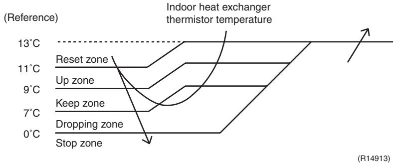
line
| Zone | Temperature | | ------------- | ----------- | | Reset zone | 13°C | | Up zone | 11°C | | Keep zone | 9°C | | Dropping zone | 7°C | | Stop zone | 0°C |4.7 Heating Peak-cut Control
Outline
During heating operation, the indoor heat exchanger temperature determines the frequency upper limit to prevent abnormal high pressure.
Detail
■ The operating frequency is judged with the indoor heat exchanger temperature 2 minutes after the operation starts and F seconds after the number of operation room is changed.
■ The maximum value of the indoor heat exchanger temperature controls the following (excluding stopped rooms).
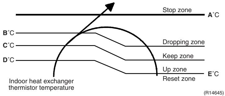
text_image
Stop zone A°C B°C D°C C°C D°C Dropping zone Keep zone Up zone Reset zone E°C Indoor heat exchanger thermistor temperature (R14645)| Zone | Control |
| Stop zone | When the temperature reaches the stop zone, the compressor stops. |
| Dropping zone | The upper limit of frequency decreases. |
| Keep zone | The upper limit of frequency is kept. |
| Up zone | The upper limit of frequency increases. |
| Reset zone | The upper limit of frequency is canceled. |
| F (seconds) | |
| When increase | 30 |
| When decrease | 2 |
4.8 Outdoor Fan Control
1. Fan ON control to cool down the electrical box
The outdoor fan is turned ON when the electrical box temperature is high while the compressor is OFF.
2. Fan OFF control during defrosting
The outdoor fan is turned OFF while defrosting.
3. Fan OFF delay when stopped
The outdoor fan is turned OFF 60 seconds after the compressor stops.
4. Fan speed control for pressure difference upkeep
The rotation speed of the outdoor fan is controlled for keeping the pressure difference during cooling operation with low outdoor temperature.
- When the pressure difference is low, the rotation speed of the outdoor fan is reduced.
When the pressure difference is high, the rotation speed of the outdoor fan is controlled as well as normal operation.
5. Fan control when the number of heating room decreases
When the outdoor temperature is more than 10^ C, the fan is turned off for 30 seconds.
6. Fan speed control during forced operation
The outdoor fan is controlled as well as normal operation during the forced operation.
7. Fan speed control during POWERFUL operation
The rotation speed of the outdoor fan is increased during the POWERFUL operation.
8. Fan speed control during indoor / outdoor unit quiet operation
The rotation speed of the outdoor fan is reduced by the command of the indoor / outdoor unit quiet operation.
9. Fan ON/OFF control when operation starts / stops
The outdoor fan is turned ON when the operation starts. The outdoor fan is turned OFF when the operation stops.
4.9 Liquid Compression Protection Function
Outline
In order to obtain the dependability of the compressor, the compressor is stopped according to the outdoor temperature and temperature of the outdoor heat exchanger.
Detail
■ Operation stops depending on the outdoor temperature
The compressor turns off under the conditions that the system is in cooling operation and outdoor temperature is below -12^ .
4.10 Defrost Control
Outline
Defrosting is carried out by the cooling cycle (reverse cycle). The defrosting time or outdoor heat exchanger temperature must be more than a certain value to finish.
Detail
Conditions for Starting Defrost
■ The starting conditions are determined with the outdoor temperature and the outdoor heat exchanger temperature.
■ The system is in heating operation.
■ The compressor operates for 6 minutes.
■ More than 38 minutes of accumulated time pass after the start of the operation, or ending the previous defrosting.
Conditions for Canceling Defrost
The target heat exchanger temperature as the canceling condition is selected in the range of 4 12^ according to the outdoor temperature.
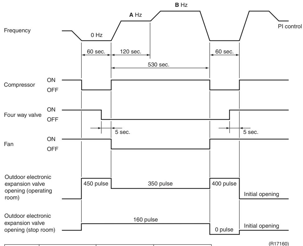
other
| Signal Type | Pulse Value | Duration (sec) | |-------------|-------------|----------------| | Compressor | ON | OFF | | Four way valve | ON | OFF | | Fan | ON | OFF | | Outdoor electronic expansion valve opening (operating room) | 450 pulse | 450 sec | | Outdoor electronic expansion valve opening (stop room) | 160 pulse | 160 sec | | Outdoor electronic expansion valve opening (operating room) | 400 pulse | 400 sec | | Outdoor electronic expansion valve opening (stop room) | 0 pulse | 0 sec | | PI control | - | - | | Frequency | 0 Hz | 0 Hz | | A Hz | - | - | | B Hz | - | - | | Current | - | - | | Time Points | 60 sec. | 60 sec. | | Duration | 120 sec. | 120 sec. | | Duration | 530 sec. | 530 sec. | | Time Points | 60 sec. | 60 sec. | | Current | - | - | | Time Points | - | - | | Current | - | - | | Current | - | - | | Current | - | - | | Current | - | - | | Current | - | - | | Current | - | - | | Current | - | - | | Current | - | - | | Current | - | - | | Current | - | - | | Current | - | - | | Current | - | - | | Current | - | - | | Current | - | - | | Current | - | - | | Current | - | - | | Current | - | - | | Current | - | - | | Current | - | - | | Current | - | - | | Current: Initial Opening: Initial opening; Initial opening: End: Initial opening; Initial operation: Initial operation; Initial operation: Stop Room; Initial operation: Stop Room; Initial operation: Stop Room; Initial operation: Stop Room; Initial operation: Stop Room; Initial operation: Stop Room; Initial operation: Stop Room; Initial operation: Stop Room; Initial operation: Stop Room; Initial operation: Stop Room; Initial operation: Stop Room; Initial operation: Stop Room; Initial operation: Stop Room; Initial operation: Stop Room; Initial operation: Stop Room; Initial operation: Stop Room; Initial operation: Stop Room; Initial operation : Initial operation: Stop Room; Initial operation : Stop Room; Initial operation : Stop Room; Initial operation : Stop Room; Initial operation : Stop Room; Initial operation : Stop Room; Initial operation : Stop Room; Initial operation : Stop Room; Initial operation : Stop Room; Initial operation : Stop Room; Initial operation : Stop Room; Initial operation : Stop Room; Initial operation : Stop Room; Initial operation : Stop Room; Initial operation : Stop Room; Initial operation : Stop Room; Initial operation : Stop Room; Initial operation : Stop Room; First Operation (R17160)| 40/50/52/58 class | 68/75 class | 80/90 class | |
| A (Hz) | 62 | 54 | 39 |
| B (Hz) | 80 | 82 | 62 |
4.11 Low Hz High Pressure Limit
Outline
The upper limit of high pressure in a low Hz zone is set. The upper limit of the indoor heat exchanger temperature is also set by the operating frequency. Zones are divided into three, reset zone, keep zone, and dropping zone, and the frequency control is carried out according to each zone.
Detail
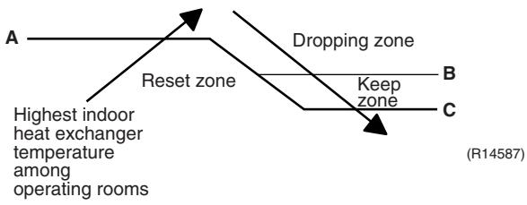
flowchart
graph TD
    A["Highest indoor heat exchanger temperature among operating rooms"] --> B["Reset zone"]
    B --> C["Dropping zone"]
    C --> D["Keep zone"]
    D --> E["C"]
    style A fill:#f9f,stroke:#333
    style B fill:#ccf,stroke:#333
    style C fill:#cfc,stroke:#333
    style D fill:#fcc,stroke:#333
| 40/50/52/58/68/75 class | 80/90 class | |
| A (°C) | 60 | 57 |
| B (°C) | 59 | 56 |
| C (°C) | 56 | 53 |

Note: Dropping: The system stops 2 minutes after staying in the dropping zone.
4.12 Outdoor Electronic Expansion Valve Control
Outline
The following items are included in the outdoor electronic expansion valve control.
Outdoor electronic expansion valve is fully closed
- Outdoor electronic expansion valve is fully closed when turning on the power.
- Pressure equalizing control
Room Distribution Control
- Gas pipe isothermal control
- SC (subcooling) control
- Liquid pipe temperature control (with all ports connected and all rooms being air-conditioned)
- Liquid pipe temperature control for stopped rooms
- Dew prevention control for indoor rotor
Open Control
- Outdoor electronic expansion valve control when starting operation
- Outdoor electronic expansion valve control when the frequency changes
- Outdoor electronic expansion valve control for defrosting
- Outdoor electronic expansion valve control for oil recovery
- Outdoor electronic expansion valve control when a discharge pipe temperature is abnormally high
- Outdoor electronic expansion valve control when the discharge pipe thermistor is disconnected
- Outdoor electronic expansion valve control for indoor unit freeze-up protection
Feedback Control
- Target discharge pipe temperature control
Detail
The followings are the examples of the outdoor electronic expansion valve control which function in each operation mode.
| ●: Holding Functions—: No Functions | Gas pipe isothermal control | SC (subcooling) control | Control when the frequency changes | Control for abnormally high discharge pipe temperature | Oil recovery control | Indoor freeze-up protection control | Liquid pipe temperature control | Liquid pipe temperature control for non-operating units | Dew prevention control for indoor rotor | |
| Operation pattern | ||||||||||
| When power is turned on | Fully closed when power is turned on | — | — | — | — | — | — | — | — | — |
| Cooling, 1 room operation | Open control when starting | — | — | — | ● | ● | ● | — | — | — |
| Cooling, 2 rooms operation to Cooling, 4 rooms operation | (Control of target discharge pipe temperature) | — | — | ● | ● | ● | ● | — | — | ● |
| Control when the operating room is changed | — | — | — | ● | ● | ● | — | — | ● | |
| (Control of target discharge pipe temperature) | ● | — | ● | ● | ● | ● | — | — | ● | |
| Stop | Pressure equalizing control | — | — | — | — | — | — | — | — | — |
| Heating, 1 room operation | Open control when starting | — | — | — | ● | — | — | — | — | — |
| Heating, 2 rooms operation | (Control of target discharge pipe temperature) | — | ★2 | ● | ● | — | — | ★1 | ★3 | — |
| Control when the operating room is changed | — | — | — | ● | — | — | — | — | — | |
| (Control of target discharge pipe temperature) | — | ★2 | ● | ● | — | — | ★1 | ★3 | — | |
| (Defrost control) | — | — | — | — | — | — | — | — | — | |
| Stop | Pressure equalizing control | — | — | — | — | — | — | — | — | — |
| Heating operation | Open control when starting | — | — | — | ● | — | — | — | — | — |
| Control of discharge pipe thermistor disconnection | Continue | — | ★2 | — | — | — | — | ★1 | ★3 | — |
| Stop | Pressure equalizing control | — | — | — | — | — | — | — | — | — |
(R16007)
★1: When all the indoor units are operating, “liquid pipe temperature control” is conducted.
★2: “SC (subcooling) control” is conducted for the operating indoor units, when some of the units are not operating.
★3: “Liquid pipe temperature control for stopped room” is conducted for the non-operating indoor units.
4.12.1 Fully Closing with Power on
The outdoor electronic expansion valve is initialized when the power is turned on. The opening position is set and the pressure equalization is developed.
4.12.2 Pressure Equalizing Control
When the compressor is stopped, the pressure equalizing control is activated. The outdoor electronic expansion valve opens, and develops the pressure equalization.
4.12.3 Opening Limit Control
| Outline | A maximum and minimum opening of the outdoor electronic expansion valve are limited. |
| Detail | ■ A maximum outdoor electronic expansion valve opening in the operating room: 450 pulses ■ A minimum outdoor electronic expansion valve opening in the operating room: 75 pulses The outdoor electronic expansion valve is fully closed in the room where cooling is stopped and is opened at a fixed degree during defrosting. |
4.12.4 Starting Operation Control / Changing Operation Room
The outdoor electronic expansion valve opening is controlled when the operation starts, and prevents superheating or liquid compression.
4.12.5 Control when the Frequency Changes
When the target discharge pipe temperature control is active, if the target frequency is changed to a specified value in a certain time period, the target discharge pipe temperature control is canceled and the target opening of the outdoor electronic expansion valve is changed.
4.12.6 Oil Recovery Function
| Outline | The outdoor electronic expansion valve opening in the cooling stopped room is set as to open for a certain time at a specified interval so that the oil in the cooling stopped room may not be accumulated. |
| Detail | During cooling operation, every 1 hour continuous operation, the outdoor electronic expansion valves in the operation stopped room is opened by 80 pulses for specified time. |
4.12.7 High Discharge Pipe Temperature Control
When the compressor is operating, if the discharge pipe temperature exceeds a certain value, the outdoor electronic expansion valve opens and the refrigerant runs to the low pressure side. This procedure lowers the discharge pipe temperature.
4.12.8 Control for Disconnection of the Discharge Pipe Thermistor
Outline
The disconnection of the discharge pipe thermistor is detected by comparing the discharge pipe temperature with the condensing temperature. If the discharge pipe thermistor is disconnected, the outdoor electronic expansion valve opens according to the outdoor temperature and the operation frequency, and operates for a specified time, and then stops.
After 3 minutes, the operation restarts and checks if the discharge pipe thermistor is disconnected. If the discharge pipe thermistor is disconnected, the system stops after operating for a specified time.
If the disconnection is detected repeatedly, the system is shut down. When the compressor runs for 60 minutes without any error, the error counter is reset.
Detail
Detect Disconnection
When the starting control (660 \~ 810 seconds) finishes, the following adjustment is made.
- When the operation mode is cooling
When the following condition is fulfilled, the discharge pipe thermistor disconnection is ascertained.
Discharge pipe temperature + 6°C < outdoor heat exchanger temperature
- When the operation mode is heating
When the following condition is fulfilled, the discharge pipe thermistor disconnection is ascertained.
Discharge pipe temperature + 6°C < highest indoor heat exchanger temperature
Adjustment when the thermistor is disconnected
When the disconnection is ascertained, the compressor continues operation for 9 minutes and then stops.
If the compressor stops repeatedly, the system is shut down.
4.12.9 Gas Pipe Isothermal Control During Cooling
When the units are operating in multiple rooms, the gas pipe temperature is detected and the outdoor electronic expansion valve opening is adjusted so that the temperature of the gas pipe in each room becomes equal.
■ When the gas pipe temperature > the average gas pipe temperature, → open the outdoor electronic expansion valve in that room
■ When the gas pipe temperature < the average gas pipe temperature, → close the outdoor electronic expansion valve in that room
The temperatures are monitored every 40 seconds.
4.12.10 SC (Subcooling) Control
Outline
The liquid pipe temperature and the heat exchanger temperature are detected and the outdoor electronic expansion valve opening is compensated so that the SC of each room becomes the target SC.
■ When the actual SC is > target SC, open the outdoor electronic expansion valve of the room.
■ When the actual SC is < target SC, close the outdoor electronic expansion valve of the room.
Detail
Start Conditions
After finishing the starting control (660 \~ 810 seconds), (all) the outdoor electronic expansion valve(s) for the operating room is/are controlled.
Determine Outdoor Electronic Expansion Valve Opening
The outdoor electronic expansion valve opening is adjusted so that the temperature difference between the maximum heat exchanger temperature of connected room and the liquid pipe temperature thermistor becomes constant.
4.12.11 Target Discharge Pipe Temperature Control
The target discharge pipe temperature is obtained from the indoor and outdoor heat exchanger temperature, and the outdoor electronic expansion valve opening is adjusted so that the actual discharge pipe temperature becomes close to the target discharge pipe temperature. (Indirect SH (superheating) control using the discharge pipe temperature)
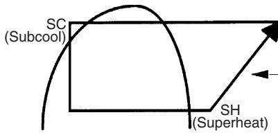
text_image
SC (Subcool) SH (Superheat)The target discharge pipe temperature is set as to become the aiming SH.
The inclination does not change depending on the operating condition.
(R14213)
The outdoor electronic expansion valve opening and the target discharge pipe temperature are adjusted every 20 seconds. The target discharge pipe temperature is controlled by indoor heat exchanger temperature and outdoor heat exchanger temperature. The opening degree of the outdoor electronic expansion valve is controlled by the followings.
♦ Target discharge pipe temperature
◆ Actual discharge pipe temperature
♦ Previous discharge pipe temperature
4.13 Malfunctions
4.13.1 Sensor Malfunction Detection
Sensor malfunction may occur either in the thermistor or current transformer (CT) system.
Relating to Thermistor Malfunction
- Outdoor heat exchanger thermistor
- Discharge pipe thermistor
- Radiation fin thermistor
- Gas pipe thermistor
- Outdoor temperature thermistor
- Liquid pipe thermistor

Relating to CT Malfunction
Refer to “CT or related abnormality” on page 315 for detail.
4.13.2 Detection of Overcurrent and Overload
Outline In order to protect the inverter, an excessive output current is detected and the OL temperature is observed to protect the compressor.
Detail ■ If the inverter current exceeds 14 \~ 20 A (depending on the model), the system shuts down the compressor.
■ If the OL (compressor head) temperature exceeds 120 \~ 130°C, the compressor stops.
4.13.3 Refrigerant Shortage Control
Outline I: Detecting by power consumption
If the power consumption is below the specified value and the frequency is higher than the specified frequency, it is regarded as refrigerant shortage.
The power consumption is low comparing with that in the normal operation when refrigerant is insufficient, and refrigerant shortage is detected by checking power consumption.
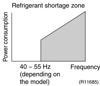
area
Refrigerant shortage zone | Frequency | Power consumption | | :--- | :--- | | 40 ~ 55 Hz (depending on the model) | Low | | Frequency | High |II : Detecting by discharge pipe temperature
If the discharge pipe temperature is higher than the target discharge pipe temperature, and the outdoor electronic expansion valve is fully open for more than the specified time, it is regarded as refrigerant shortage.
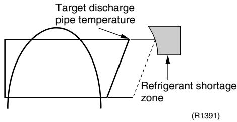
text_image
Target discharge pipe temperature Refrigerant shortage zone (R1391)
Refer to "Refrigerant shortage" on page 296 for detail.
4.13.4 Anti-icing Function
During cooling, if the indoor heat exchanger temperature in the operation stopped room becomes below the specified temperature for the specified time, the outdoor electronic expansion valve is opened in the operation stopped room as specified, and the fully closed operation is carried out. After this, if freezing abnormality occurs more than specified time, the system shuts down as the system abnormality.
Part 5
Operation Manual
- System Configuration....125
- RA Indoor Unit....126
2.1 FTXG, FTXS-K, CTXS, FVXG Series - ARC466A1, A2, A6 ..... 126
2.2 FTXS-J, FTXS-G, FVXS Series - ARC452A1, A3....178
2.3 FLXS, FDXS Series - ARC433B67, B69 218
- SA Indoor Unit....233
3.1 BRC1D528 233
1. System Configuration
After installation and trial operation of the room air conditioner are completed, the air conditioner should be handled and operated as described in the following pages. Every user should be informed on the correct method of operation and how to check if it can cool (or heat) well, and how to use it efficiently.
Providing instructions to the user can reduce requests for servicing by 80%. However proficient the installation and operating functions of the air conditioning system are, the customer may fault either the room air conditioner or its installation work when it is actually due to improper handling. The installation work and the handing-over of the unit can only be considered completed when its handling has been fully explained to the user without using technical terms, and while imparting full knowledge of the equipment.
2. RA Indoor Unit
2.1 FTXG, FTXS-K, CTXS, FVXG Series - ARC466A1, A2, A6
2.1.1 Manual Contents and Reference Page
| Model Series | Wall Mounted Type | Floor Standing Type | |
| FTXG25-50JV1BW(A) | FTXS20/25K2V1B CTXS15/35K2V1B | FVXG25-50K2V1B | |
| Read Before Operation | |||
| Names of Parts | 127 | 131 | 135 |
| Preparation before Operation | 139 ★2 | 139 ★2 | 139 |
| Operation | |||
| AUTO · DRY · COOL · HEAT · FAN Operation | 141 | 143 | 145 |
| RADIANT Operation | — | — | 146 |
| Temperature Setting | — | — | 147 |
| Adjusting the Airflow Direction and Rate | 148 | 150 | 152 |
| COMFORT AIRFLOW Operation | 154 ★1 | 154 | — |
| INTELLIGENT EYE Operation | 155 ★1 | 155 | — |
| POWERFUL Operation | 157 ★1 | 157 | 158 |
| OUTDOOR UNIT QUIET Operation | 159 ★2 | 159 ★2 | 159 |
| ECONO Operation | 160 ★2 | 160 ★2 | 160 |
| OFF TIMER Operation | 161 | 162 | 163 |
| ON TIMER Operation | 164 | 165 | 166 |
| WEEKLY TIMER Operation | 167 ★2 | 167 ★2 | 167 |
| Note for Multi System | 173 | 173 | 173 |
| Quick Reference | 175 ★1 | 176 | 177 |
| Drawing No. | 3P255639-2A (Reference) | 3P297033-1 | 3P276869-1 |
★1: Illustrations are for FTXS-K and CTXS-K series as representative.
★2: Illustrations are for FVXG series as representative.
2.1.2 Name of Parts
FTXG25/35/50JV1BW(A)
Name of Parts
Indoor Unit
- Appearance of the indoor unit may differ.
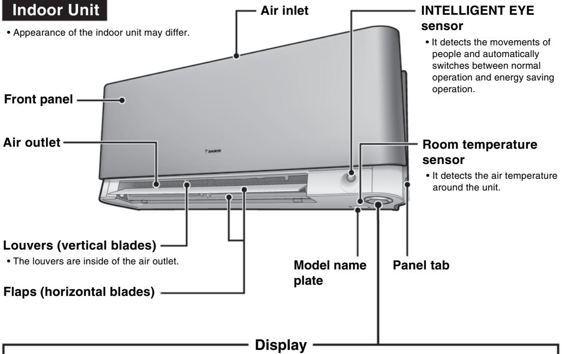
text_image
Indoor Unit • Appearance of the indoor unit may differ. Front panel Air outlet Louvers (vertical blades) • The louvers are inside of the air outlet. Flaps (horizontal blades) Air inlet INTELLIGENT EYE sensor • It detects the movements of people and automatically switches between normal operation and energy saving operation. Room temperature sensor • It detects the air temperature around the unit. Model name plate Panel tab DisplayINTELLIGENT EYE lamp (green)
Signal receiver and Indoor unit ON/OFF switch
Signal receiver
- It receives signals from the remote controller.
- When the unit receives a signal, you will hear a beep sound.
| Case | Sound type |
| Operation start | beep-beep |
| Setting changed | beep |
| Operation stop | long beep |
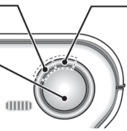
natural_image
Diagram of a mechanical or electrical component with concentric rings and dashed lines indicating internal features (no text or symbols)Multi-monitor lamp and TIMER lamp
Multi-monitor lamp
- The lamp colour changes according to the operation.
| Operation | Multi-monitor lamp |
| AUTO | Red/Blue |
| DRY | Green |
| COOL | Blue |
| HEAT | Red |
| FAN | White |
| TIMER | Orange |
TIMER lamp
- When operation by timer has been set, the multi-monitor lamp periodically changes to orange. After lighting orange for about 5 seconds, it returns to the colour of the operation mode. The multi-monitor lamp will turn orange on and off in cyclic manner while the air conditioner is not in operation.
Indoor unit ON/OFF switch
- Press this switch once to start operation. Press once again to stop it.
- The operation mode refer to the following table.
| Mode | Temperature setting | Airflow rate |
| AUTO | 25°C | AUTO |
- This switch is useful when the remote controller is missing.
TIMER lamp colour : For COOL
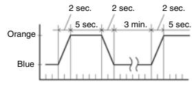
TIMER lamp colour
■ Open the front panel
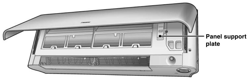
text_image
Panel support plate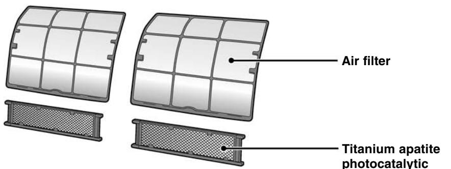
text_image
Air filter Titanium apatite photocatalyticName of Parts
Remote Controller
Signal transmitter
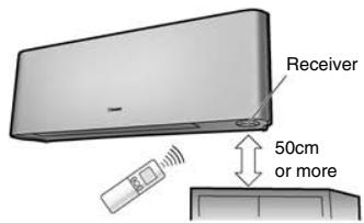
text_image
Receiver 50cm or more- To use the remote controller, aim the transmitter at the indoor unit. If there is anything to block signals between the unit and the remote controller, such as a curtain, the unit will not operate.
- Do not drop the remote controller. Do not get it wet.
- The maximum distance for communication is approx. 6m. Make sure that there are no obstacles within 50cm under the signal receiver.
Such obstacles, if any, may have an adverse influence on the reception performance of the receiver and the reception distance may be shortened.
FAN setting button
- It selects the airflow rate setting.
POWERFUL button
- POWERFUL operation.
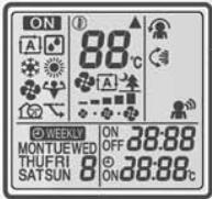
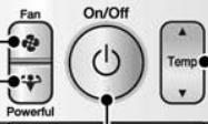
Display (LCD)
- It displays the current settings. (In this illustration, each section is shown with its displays on for the purpose of explanation.)
TEMPERATURE adjustment buttons
- It changes the temperature setting.
ON/OFF button
- Press this button once to start operation. Press once again to stop it.
Front cover
- Open the front cover.
Model
ARC466A1
■ Open the front cover

text_image
MODE selector button • It selects the operation mode. (AUTO/DRY/COOL/HEAT/ FAN) ECONO button • ECONO operation. SWING button • Adjusting the airflow direction. INTELLIGENT EYE button • INTELLIGENT EYE operation. QUIET button • OUTDOOR UNIT QUIET operation. COMFORT button • COMFORT AIRFLOW operation. OFF TIMER button TIMER CANCEL button • It cancels the timer setting. • It cannot be used for the WEEKLY TIMER operation. SELECT button • It changes the ON/OFF TIMER and WEEKLY TIMER settings. CLOCK buttonFTXS20/25K2V1B, CTXS15/35K2V1B
Name of Parts
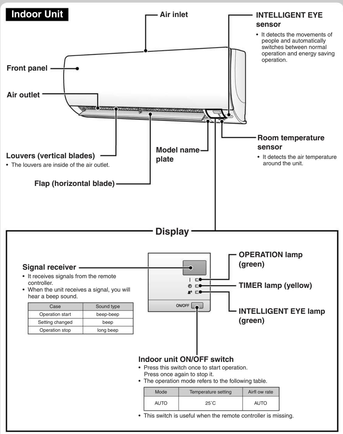
text_image
Indoor Unit Front panel Air outlet Louver (vertical blades) • The louvers are inside of the air outlet. Flap (horizontal blade) Air inlet INTELLIGENT EYE sensor • It detects the movements of people and automatically switches between normal operation and energy saving operation. Room temperature sensor • It detects the air temperature around the unit. Display Signal receiver • It receives signals from the remote controller. • When the unit receives a signal, you will hear a beep sound. Operation lamp (green) TIMER lamp (yellow) INTELLIGENT EYE lamp (green) ON/OFF Case Sound type Operation start beep-beep Setting changed beep Operation stop long beep Indoor unit ON/OFF switch • Press this switch once to start operation. Press once again to stop it. • The operation mode refers to the following table. Mode Temperature setting Airflow rate AUTO 25°C AUTO • This switch is useful when the remote controller is missing.■ Open the front panel
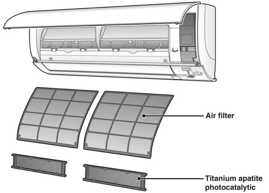
text_image
Air filter Titanium apatite photocatalyticName of Parts
Remote Controller
Signal transmitter
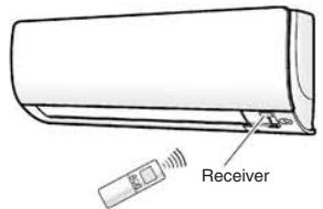
text_image
Receiver- To use the remote controller, aim the transmitter at the indoor unit. If there is anything to block signals between the unit and the remote controller, such as a curtain, the unit will not operate.
- Do not drop the remote controller. Do not get it wet.
- The maximum distance for communication is approx. 7m.
FAN setting button
- It selects the airflow rate setting.
POWERFUL button
- POWERFUL operation.
| Model | ARC466A6 |
Display (LCD)
- It displays the current settings. (In this illustration, each section is shown with its displays on for the purpose of explanation.)
TEMPERATURE adjustment buttons
- It changes the temperature setting.
ON/OFF button
- Press this button once to start operation. Press once again to stop it.
Front cover
- Open the front cover.
■ Open the front cover
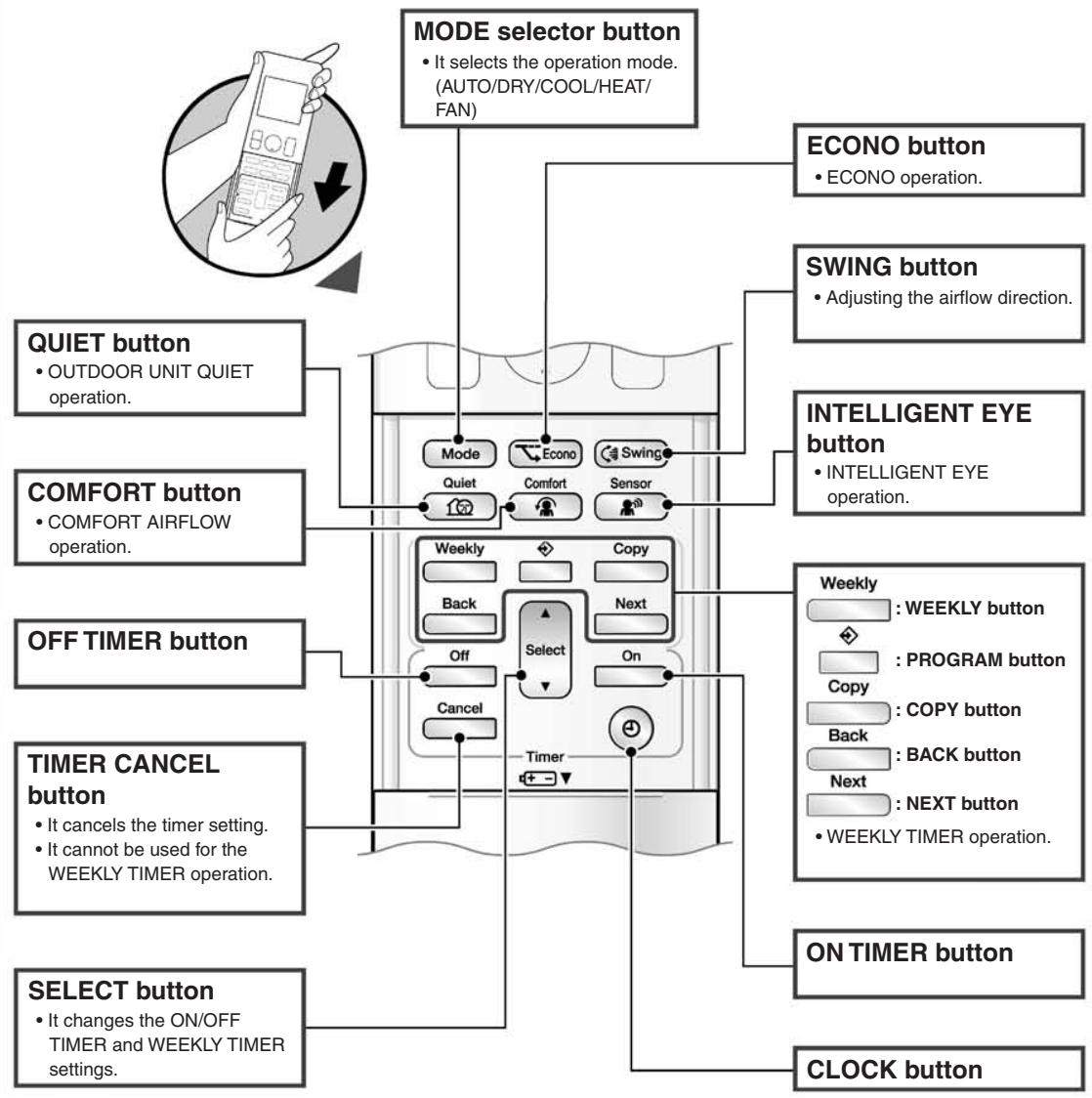
flowchart
graph TD
    A["MODE selector button"] --> B["MODE"]
    A --> C["ECONO button"]
    A --> D["SWING button"]
    A --> E["INTELLIGENT EYE button"]
    A --> F["ON TIMER button"]
    A --> G["CLOCK button"]

    B --> H["Mode"]
    B --> I["Quiet"]
    B --> J["Back"]
    B --> K["Cancel"]
    B --> L["Comfort"]
    B --> M["Sensor"]

    C --> N["ECONO operation."]
    D --> O["Adjusting the airflow direction."]

    F --> P["Weekly: WEEKLY button"]
    F --> Q["Copy: PROGRAM button"]
    F --> R["Back: COPY button"]
    F --> S["Next: NEXT button"]

    G --> T["ON TIMER button"]
    G --> U["SELECT button"]

    V["QUIET button"] --> W["OUTDOOR UNIT QUIET operation."]

    X["COMFORT button"] --> Y["COMFORT AIRFLOW operation."]

    Z["OFF TIMER button"] --> AA["Off Timer setting."]
    Z --> AB["Select Timer setting."]
    Z --> AC["IT cannot be used for the WEEKLY TIMER operation."]

    AD["TIMER CANCEL button"] --> AE["It cancels the timer setting."]
    AD --> AF["IT cannot be used for the WEEKLY TIMER operation."]

    AG["SELECT button"] --> AH["It changes the ON/OFF TIMER and WEEKLY TIMER settings."]
FVXG25/35/50K2V1B
Name of Parts
Indoor Unit
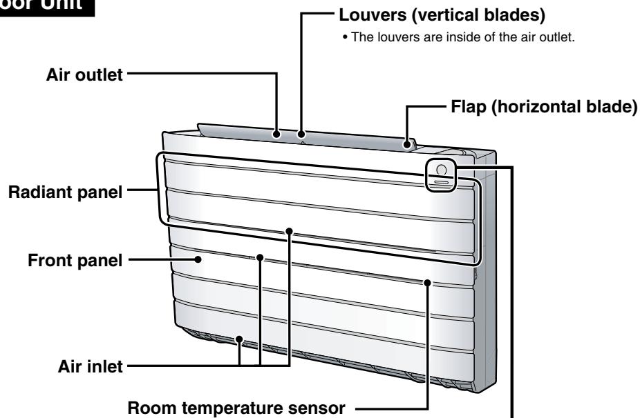
text_image
Louver (vertical blades) • The louvers are inside of the air outlet. Flap (horizontal blade) Air outlet Radiant panel Front panel Air inlet Room temperature sensor- It detects the air temperature around the unit.
Display
Signal receiver and Indoor unit ON/OFF switch
Signal receiver
- It receives signals from the remote controller.
- When the unit receives a signal, you will hear a beep sound.
| Case | Sound type |
| Operation start | beep-beep |
| Setting changed | beep |
| Operation stop | long beep |
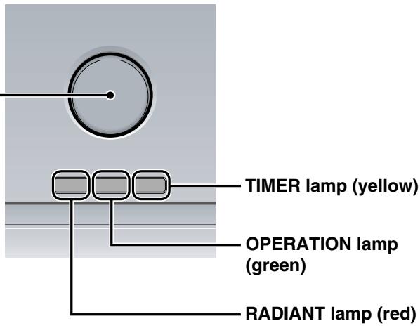
text_image
TIMER lamp (yellow) OPERATION lamp (green) RADIANT lamp (red)Indoor unit ON/OFF switch
- Press this switch once to start operation. Press once again to stop it.
- The operation mode refer to the following table.
| Mode | Temperature setting | Airflow rate |
| AUTO | 25°C | AUTO |
- This switch is useful when the remote controller is missing.
■ Open the front panel
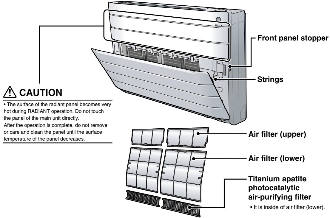
text_image
Front panel stopper Strings CAUTION • The surface of the radiant panel becomes very hot during RADIANT operation. Do not touch the panel of the main unit directly. After the operation is complete, do not remove or care and clean the panel until the surface temperature of the panel decreases. Air filter (upper) Air filter (lower) Titanium apatite photocatalytic air-purifying filter • It is inside of air filter (lower).Name of Parts
Remote Controller
Signal transmitter
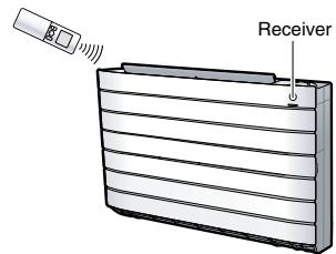
text_image
Receiver- To use the remote controller, aim the transmitter at the indoor unit. If there is anything to block signals between the unit and the remote controller, such as a curtain, the unit will not operate.
- Do not drop the remote controller. Do not get it wet.
- The maximum distance for communication is approximately 7m.
FAN setting button
- It selects the airflow rate setting.
RADIANT switching button
- RADIANT operation.
| Model | ARC466A2 |
Display (LCD)
- It displays the current settings. (In this illustration, each section is shown with its displays on for the purpose of explanation.)
TEMPERATURE adjustment buttons
- It changes the temperature setting.
ON/OFF button
- Press this button once to start operation.
Press once again to stop it.
Front cover
- Open the front cover.
■ Open the front cover
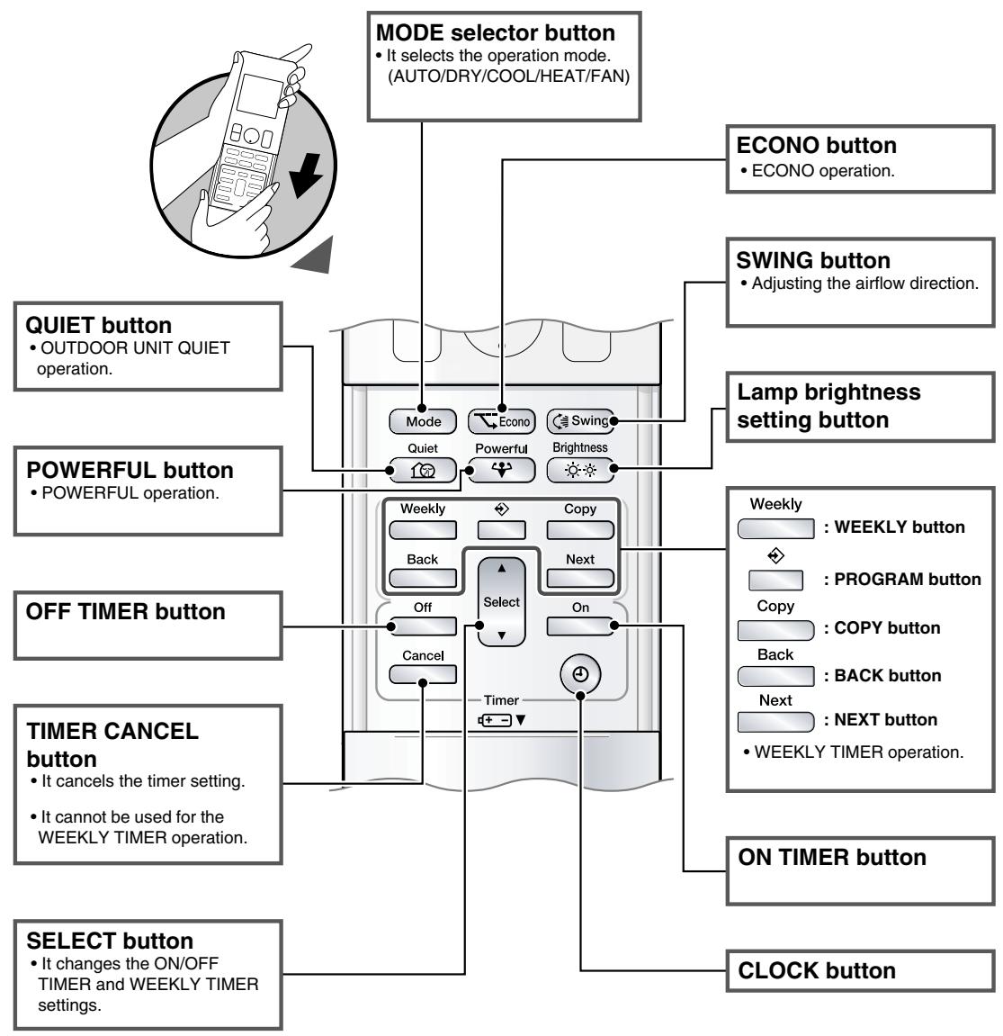
flowchart
graph TD
    A["MODE selector button"] --> B["ECONO button"]
    A --> C["SWING button"]
    A --> D["Lamp brightness setting button"]
    A --> E["ON TIMER button"]
    A --> F["CLOCK button"]
    A --> G["SELECT button"]
    A --> H["TIMER CANCEL button"]
    A --> I["OFF TIMER button"]
    A --> J["POWERFUL button"]
    A --> K["QUIET button"]
    A --> L["MODE selection: AUTO/DRY/COOL/HEAT/FAN"]

    B --> M["ECONO operation."]
    C --> N["Adjusting the airflow direction."]
    D --> O["Lamp brightness setting button"]
    E --> P["OK Timer"]
    F --> Q["OK Timer"]
    G --> R["OK Timer"]
    H --> S["OK Timer"]
    I --> T["OK Timer"]

    subgraph Mode
        U["Mode"] --> V["Econo"] --> W["Swing"] --> X["Switch"] --> Y["Quiet"] --> Z["Powerful"] --> AA["Brightness"] --> AB["Back"]
        AC["Off"] --> AD["Cancel"] --> AE["Select"] --> AF["On"] --> AG["Timer"]
    end

    subgraph Tools
        AH["Weekly"] --> AI[": WEEKLY button"] --> AJ[": PROGRAM button"] --> AK["Copy"] --> AL["Back"] --> AM[": BACK button"] --> AN["Next"] --> AO[": NEXT button"] --> AP["• WEEKLY TIMER operation."]
    end

    subgraph Settings
        AQ["OK Timer"] --> AR["OK Timer"]
        AS["OK Timer"] --> AT["OK Timer"]
        AU["OK Timer"] --> AV["OK Timer"]
        AW["OK Timer"] --> AX["OK Timer"]
        AY["OK Timer"] --> AZ["OK Timer"]
        BA["OK Timer"] --> BB["OK Timer"]
        BC["OK Timer"] --> BD["OK Timer"]
        BE["OK Timer"] --> BF["OK Timer"]
        BG["OK Timer"] --> BH["OK Timer"]
        BI["OK Timer"] --> BJ["OK Timer"]
        BK["OK Timer"] --> BL["OK Timer"]
        BM["OK Timer"] --> BN["OK Timer"]
        BO["OK Timer"] --> BP["OK Timer"]
        BQ["OK Timer"] --> BR["OK Timer"]
        BS["OK Timer"] --> BT["OK Timer"]
        BU["OK Timer"] --> BV["OK Timer"]
        BW["OK Timer"] --> BX["OK Timer"]
        BY["OK Timer"] --> BZ["OK Timer"]
        CA["OK Timer"] --> CB["OK Timer"]
        CC["OK Timer"] --> CD["OK Timer"]
        DE["OK Timer"] --> DF["OK Timer"]
        DG["OK Timer"] --> DH["OK Timer"]
        DI["OK Timer"] --> DJ["OK Timer"]
        DK["OK Timer"] --> DL["OK Timer"]
        DM["OK Timer"] --> DJ
    end
2.1.3 Preparation before Operation
Preparation before Operation
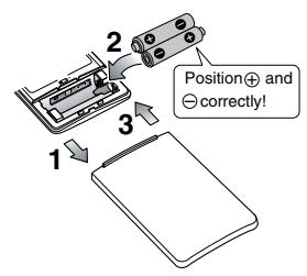
text_image
Position⊕ and ⊖ correctly!■ To set the batteries
- Slide the front cover to take it off.
- Set two dry batteries AAA.LR03 (alkaline).
- Set the front cover as before.
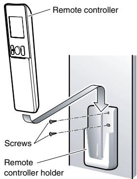
text_image
Remote controller Screws Remote controller holder■ To fix the remote controller holder on the wall
- Choose a place from where the signals reach the unit.
- Fix the holder to a wall, a pillar, or similar location with the screws procured locally
- Place the remote controller in the remote controller holder.
■ To set the luminance of the display
- The luminance of the indoor unit display can be set.
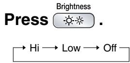
NOTE
■ Notes on batteries
- When replacing the batteries, use batteries of the same type, and replace both old batteries together.
- When the system is not used for a long time, take the batteries out.
- The batteries will last for approximately 1 year. If the remote controller display begins to fade and the degradation of reception performance occurs within a year, however, replace both batteries with new, size AAA.LR03 (alkaline).
- The attached batteries are provided for the initial use of the system.
The usable period of the batteries may be short depending on the manufactured date of the air conditioner.
■ Notes on remote controller
- Never expose the remote controller to direct sunlight.
- Dust on the signal transmitter or receiver will reduce the sensitivity. Wipe off dust with soft cloth.
- Signal communication may be disabled if an electronic-starter-type fluorescent lamp (such as inverter-type lamps) is in the room. Consult the shop if that is the case.
- If the remote controller signals happen to operate another appliance, move that appliance to somewhere else, or consult the service shop.
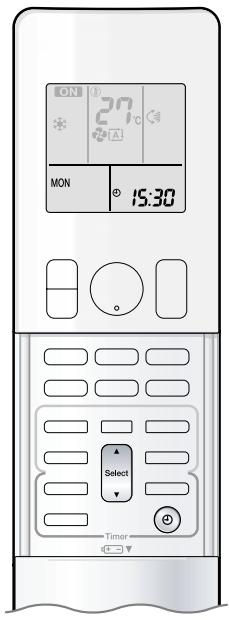
text_image
ON 27°C MON 15:30 Select Timer■ Turn the breaker on
- After the power is turned on, the flap of the indoor unit opens and closes once to set the reference position.
■ To set the clock
1. Press ⏻.
- “0:00” is displayed on the LCD.
- “MON” and “💡” blink.
2. Press Select to set the current day of the week.
3. Press ⏻ .
- “💡” blinks.
4. Press Select to set the clock to the present time.
- Holding down ▲ or ▼ rapidly increases or decreases the time display.
5. Press ☑ .
- Point the remote controller at the indoor unit when pressing the buttons.
- “:” blinks.
NOTE
■ Note on setting the clock
- If the indoor unit's internal clock is not set to the correct time, the ON TIMER, OFF TIMER and WEEKLY TIMER will not operate punctually.
text_image
ON 27°C MON 15:30 On/Off Mode TimerThe air conditioner operates with the operation mode of your choice.
From the next time on, the air conditioner will operate with the same operation mode.
■ To start operation
1. Press Mode and select an operation mode.
• Each pressing of the button advances the mode setting in sequence.
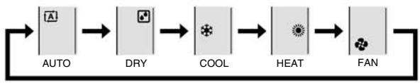
flowchart
graph LR
    A["AUTO"] --> B["DRY"]
    B --> C["COOL"]
    C --> D["HEAT"]
    D --> E["FAN"]
2. Press Ⓧ.
- “ON” is displayed on the LCD.
- The multi-monitor lamp lights up.
The colour of the lamp varies depending on the operation mode.

Display
| Operation | Multi-monitor lamp |
| AUTO | Red/Blue |
| DRY | Green |
| COOL | Blue |
| HEAT | Red |
| FAN | White |
■ To stop operation
Press On/Off again.
- “ON” disappears from the LCD.
- The multi-monitor lamp goes off.
NOTE
| MODE | Notes on each operation mode |
| HEAT | Since this air conditioner heats the room by taking heat from outdoor air to indoors, the heating capacity becomes smaller in lower outdoor temperatures. If the heating effect is insufficient, it is recommended to use another heating appliance in combination with the air conditioner.The heat pump system heats the room by circulating hot air around all parts of the room. After the start of HEAT operation, it takes some time before the room gets warmer.In HEAT operation, frost may occur on the outdoor unit and lower the heating capacity. In that case, the system switches into defrosting operation to take away the frost.During defrosting operation, hot air does not flow out of indoor unit. |
| COOL | This air conditioner cools the room by releasing the heat in the room outside.Therefore, the cooling performance of the air conditioner may be degraded if the outdoor temperature is high |
| DRY | The computer chip works to rid the room of humidity while maintaining the temperature as much as possible. It automatically controls temperature and airflow rate, so manual adjustment of these functions is unavailable. |
| AUTO | In AUTO operation, the system selects an appropriate operation mode (COOL or HEAT) based on the room and outside temperatures and starts the operation.The system automatically reselects setting at a regular interval to bring the room temperature to user-setting level. |
| FAN | This mode is valid for fan only. |
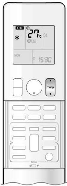
text_image
ON 27°C MON 15:30 Temp Timer■ To change the temperature setting
Press

- The displayed items on the LCD will change whenever either one of the buttons is pressed.
| COOL operation | HEAT operation | AUTO operation | DRY or FAN operation |
| 18-32°C | 10-30°C | 18-30°C | The temperature setting is not variable. |
| Press ▲ to raise the temperature and press ▼ to lower the temperature. | |||
■ Operating conditions
■ Recommended temperature setting
- For cooling: 26-28°C
- For heating: 20-24°C
■ Tips for saving energy
- Be careful not to cool (heat) the room too much.
Keeping the temperature setting at a moderate level helps save energy.
- Cover windows with a blind or a curtain.
Blocking sunlight and air from outdoors increases the cooling (heating) effect.
- Clogged air filters cause inefficient operation and waste energy. Clean them once in about every 2 weeks.
■ Notes on the operating conditions
- The outdoor unit consumes some power to have its electric components work even while it is not operating.
Connecting outdoor unit RXG25/35: 1-15W
Other outdoor units: 15-20W
The outdoor unit consumes 40 to 55W of power at the time of compressor preheating.
- If you are not going to use the air conditioner for a long period, for example in spring or autumn, turn the breaker off.
- Use the air conditioner in the following conditions.
| MODE | Operating conditions | If operation is continued out of this range |
| COOL | Outdoor temperature : <2/3/4/5MXS> -10-46°C-10-46°CIndoor temperature : 18-32°CIndoor humidity : 80% max. | A safety device may work to stop the operation.(In multi system, it may work to stop the operation of the outdoor unit only.)Condensation may occur on the indoor unit and drip. |
| HEAT | Outdoor temperature : <2MXS> -10-24°C<3/4/5MXS> -15-24°C-15-24°CIndoor temperature : 10-30°C | A safety device may work to stop the operation. |
| DRY | Outdoor temperature : <2/3/4/5MXS> -10-46°C-10-46°CIndoor temperature : 18-32°CIndoor humidity : 80% max. | A safety device may work to stop the operation.Condensation may occur on the indoor unit and drip. |
- Operation outside this humidity or temperature range may cause a safety device to disable the system.
FTXS20/25K2V1B, CTXS15/35K2V1B

The air conditioner operates with the operation mode of your choice.
From the next time on, the air conditioner will operate with the same operation mode.
■ To start operation
1. Press Mode and select an operation mode.
• Each pressing of the button advances the mode setting in sequence.
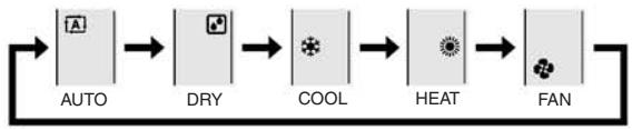
flowchart
graph LR
    A["AUTO"] --> B["DRY"]
    B --> C["COOL"]
    C --> D["HEAT"]
    D --> E["FAN"]
2. Press ⏻ .
- “ON” is displayed on the LCD.
• The OPERATION lamp lights green.

Display
■ To stop operation
Press On/Off again.
- “ON” disappears from the LCD.
- The OPERATION lamp goes off.
NOTE
| MODE | Notes on each operation mode |
| HEAT | Since this air conditioner heats the room by taking heat from outdoor air to indoors, the heating capacity becomes smaller in lower outdoor temperatures. If the heating effect is insufficient, it is recommended to use another heating appliance in combination with the air conditioner.The heat pump system heats the room by circulating hot air around all parts of the room. After the start of HEAT operation, it takes some time before the room gets warmer.In HEAT operation, frost may occur on the outdoor unit and lower the heating capacity. In that case, the system switches into defrosting operation to take away the frost.During defrosting operation, hot air does not flow out of indoor unit. |
| COOL | This air conditioner cools the room by releasing the heat in the room outside.Therefore, the cooling performance of the air conditioner may be degraded if the outdoor temperature is high |
| DRY | The computer chip works to rid the room of humidity while maintaining the temperature as much as possible. It automatically controls temperature and airflow rate, so manual adjustment of these functions is unavailable. |
| AUTO | In AUTO operation, the system selects an appropriate operation mode (COOL or HEAT) based on the room and outside temperatures and starts the operation.The system automatically reselects setting at a regular interval to bring the room temperature to user-setting level. |
| FAN | This mode is valid for fan only. |
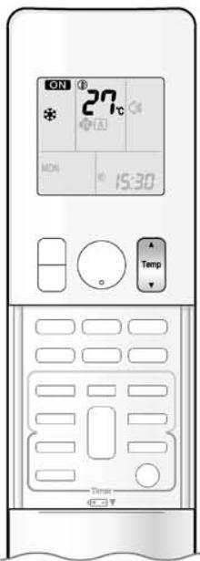
text_image
ON 27°C MON 15:30 Temp Time■ To change the temperature setting
Press

- The displayed items on the LCD will change whenever either one of the buttons is pressed.
| COOL operation | HEAT operation | AUTO operation | DRY or FAN operation |
| 18-32°C | 10-30°C | 18-30°C | The temperature setting is not variable. |
| Press ▲ to raise the temperature and press ▼ to lower the temperature. | |||
■ Operating conditions
■ Recommended temperature setting
- For cooling: 26-28°C
- For heating: 20-24°C
■ Tips for saving energy
- Be careful not to cool (heat) the room too much.
Keeping the temperature setting at a moderate level helps save energy. - Cover windows with a blind or a curtain.
Blocking sunlight and air from outdoors increases the cooling (heating) effect. - Clogged air filters cause inefficient operation and waste energy. Clean them once in about every 2 weeks.
■ Notes on the operating conditions
- The outdoor unit consumes some power to have its electric components work even while it is not operating.
Connecting outdoor unit RXS20/25: 1-15W
Other outdoor units: 15-20W
The outdoor unit consumes 40 to 55W of power at the time of compressor preheating.
- If you are not going to use the air conditioner for a long period, for example in spring or autumn, turn the breaker off.
- Use the air conditioner in the following conditions.
| MODE | Operating conditions | If operation is continued out of this range |
| COOL | Outdoor temperature: <2MXS> 10-46°C<3/4/5MXS> -10-46°C-RXS> -10-46°CIndoor temperature: 18-32°CIndoor humidity: 80% max. | A safety device may work to stop the operation.(In multi system, it may work to stop the operation of the outdoor unit only.)Condensation may occur on the indoor unit and drip. |
| HEAT | Outdoor temperature: <2/3/4/5MXS> -15-24°C-RXS> -15-24°CIndoor temperature: 10-30°C | A safety device may work to stop the operation. |
| DRY | Outdoor temperature: <2MXS> 10-46°C<3/4/5MXS> -10-46°C-RXS> -10-46°CIndoor temperature: 18-32°CIndoor humidity: 80% max. | A safety device may work to stop the operation.Condensation may occur on the indoor unit and drip. |
- Operation outside this humidity or temperature range may cause a safety device to disable the system.
FVXG25/35/50K2V1B

text_image
ON 27°C MON 15:30 On/Off Mode TimerThe air conditioner operates with the operation mode of your choice. From the next time on, the air conditioner will operate with the same operation mode.
■ To start operation
1. Press Mode and select an operation mode.
• Each pressing of the button advances the mode setting in sequence.
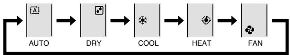
flowchart
graph LR
    A["AUTO"] --> B["DRY"]
    B --> C["COOL"]
    C --> D["HEAT"]
    D --> E["FAN"]
2. Press ⏻ .
- “ON” is displayed on the LCD.
• The OPERATION lamp lights green.

Display
■ To stop operation
Press On/Off again.
- “ON” disappears from the LCD.
• The OPERATION lamp goes off.
NOTE
| MODE | Notes on each operation mode |
| HEAT | Since this air conditioner heats the room by taking heat from outdoor air to indoors, the heating capacity becomes smaller in lower outdoor temperatures. If the heating effect is insufficient, it is recommended to use another heating appliance in combination with the air conditioner.The heat pump system heats the room by circulating hot air around all parts of the room. After the start of HEAT operation, it takes some time before the room gets warmer.In HEAT operation, frost may occur on the outdoor unit and lower the heating capacity. In that case, the system switches into defrosting operation to take away the frost.During defrosting operation, hot air does not flow out of indoor unit. |
| COOL | This air conditioner cools the room by releasing the heat in the room outside.Therefore, the cooling performance of the air conditioner may be degraded if the outdoor temperature is high.When the outdoor temperature is lower than 10^ , do not use COOL operation. If the operation is used when the outdoor temperature is lower than 10^ , the protective function of the main unit works and this disables the operation. |
| DRY | The computer chip works to rid the room of humidity while maintaining the temperature as much as possible. It automatically controls temperature and airflow rate, so manual adjustment of these functions is unavailable. |
| AUTO | In AUTO operation, the system selects an appropriate operation mode (COOL or HEAT) based on the room and outside temperatures and starts the operation.The system automatically reselects setting at a regular interval to bring the room temperature to user-setting level. |
| FAN | This mode is valid for fan only. |
2.1.5 RADIANT Operation

RADIANT Operation
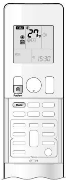
text_image
ON 27°C MON 15:30 Radiant Mode TimerThe RADIANT operation provides a comfortable environment with quiet and currentless heating operation in addition to the HEAT operation mode. The RADIANT operation has 2 operation modes.
■ To start RADIANT operation
1. Press Mode and select an HEAT operation.
• Each pressing of the button advances the mode setting in sequence.
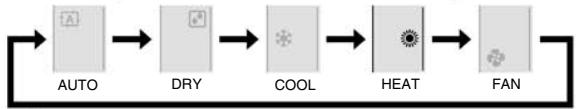
flowchart
graph LR
    A["A"] --> B["DRY"]
    B --> C["COOL"]
    C --> D["HEAT"]
    D --> E["FAN"]
- “☀️” is displayed on the LCD.
2. Press Radiant and select a RADIANT operation.
- “” is displayed on the LCD.
• The RADIANT lamp lights red. - This button can be used only in the HEAT operation mode.
- When the RADIANT operation starts, the temperature of the radiant panel increases.
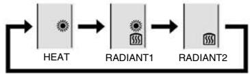
flowchart
graph LR
    A["HEAT"] --> B["RADIANT1"]
    B --> C["RADIANT2"]
Display
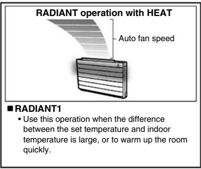
text_image
RADIANT operation with HEAT Auto fan speed ■ RADIANT1 • Use this operation when the difference between the set temperature and indoor temperature is large, or to warm up the room quickly.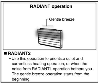
text_image
RADIANT operation Gentle breeze ■ RADIANT2 • Use this operation to prioritize quiet and currentless heating operation, or when the noise from RADIANT1 operation bothers you. The gentle breeze operation starts from the beginning.CAUTION
- During the RADIANT operation, the surface temperature of the panel will be about 55^ at maximum.
Even after the RADIANT operation is finished, the surface temperature of the panel of the air conditioner stays hot for a while. Do not touch the air conditioner until the surface temperature of the panel decreases.
Be careful that children do not touch the surface of the panel.
NOTE
■ Notes on RADIANT operation
- If RADIANT2 operation does not warm up the room, use HEAT or RADIANT1 operation.
- RADIANT1 can be used with POWERFUL operation. RADIANT2 cannot be used with the POWERFUL operation.
- This operation may not warm up the room adequately depending on conditions such as an extremely low outside temperature and lack of adequate performance.
- The RADIANT operation uses the auto fan speed, so the airflow rate cannot be changed.
- When the indoor units are connected using a multi system, please refer to "Selecting the operation mode" in note for multi system.
2.1.6 Temperature Setting
Temperature Setting
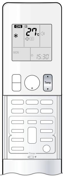
text_image
ON 27°C MON 15:30 Temp Timer■ To change the temperature setting
Press

- The displayed items on the LCD will change whenever either one of the buttons is pressed.
| COOL operation | HEAT or RADIANT operation | AUTO operation | DRY or FAN operation |
| 18-32°C | 10-30°C | 18-30°C | The temperature setting is not variable. |
| Press ▲ to raise the temperature and press ▼ to lower the temperature. | |||
■ Operating conditions
■ Recommended temperature setting
• For cooling: 26-28°C
- For heating: 20-24°C
■ Tips for saving energy
- Be careful not to cool (heat) the room too much.
Keeping the temperature setting at a moderate level helps save energy.
- Cover windows with a blind or a curtain.
Blocking sunlight and air from outdoors increases the cooling (heating) effect.
- Clogged air filters cause inefficient operation and waste energy. Clean them once in about every 2 weeks.
■ Notes on the operating conditions
- The outdoor unit consumes some power to have its electric components work even while it is not operating.
Connecting outdoor unit RXG25/35: 1-15W
Other outdoor units: 15-20W
The outdoor unit consumes 40 to 55W of power at the time of compressor preheating.
- If you are not going to use the air conditioner for a long period, for example in spring or autumn, turn the breaker off.
- Use the air conditioner in the following conditions.
| MODE | Operating conditions | If operation is continued out of this range |
| COOL | Outdoor temperature: <2/3/4/5MXS> 10-46°C10-46°CIndoor temperature: 18-32°CIndoor humidity: 80% max. | A safety device may work to stop the operation.(In multi system, it may work to stop the operation of the outdoor unit only.)Condensation may occur on the indoor unit and drip. |
| HEAT or RADIANT | Outdoor temperature: <2MXS> -10-24°C<3/4/5MXS> -15-24°C10-24°CIndoor temperature: 10-30°C | A safety device may work to stop the operation. |
| DRY | Outdoor temperature: <2/3/4/5MXS> 10-46°C10-46°CIndoor temperature: 18-32°CIndoor humidity: 80% max. | A safety device may work to stop the operation.Condensation may occur on the indoor unit and drip. |
- Operation outside this humidity or temperature range may cause a safety device to disable the system.
2.1.7 Adjusting the Airflow Direction and Rate
FTXG25/35/50JV1BW(A)

Adjusting the Airflow Direction and Rate
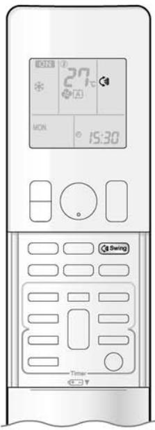
text_image
27 21°C MON 15:30 Swing TimerYou can adjust the airflow direction to increase your comfort.
■ To start auto swing
Upper and lower airflow direction
Press

- “C” is displayed on the LCD.
- The flaps (horizontal blades) will begin to swing.
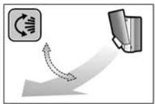
■ To set the flaps at desired position
- This function is effective while flaps are in auto swing mode.
Press Swing when the flaps have reached the desired position.
- “C” disappears from the LCD.
■ To adjust the louvers at desired position
Hold the knob and move the louvers.
- You will find a knob on the left-side and the right-side blades.
- When the unit is installed in the corner of a room, the direction of the louvers (vertical blades) should be facing away from the wall.
If they face the wall, the wall will block off the wind, causing the cooling (or heating) efficiency to drop.
- If the flaps are in the way, press Swing on the remote controller to move the flaps out of the way and then adjust the louvers.
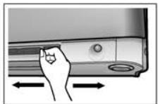
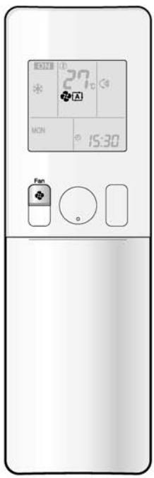
text_image
27°C MON 15:30 Fan■ To adjust the airflow rate setting
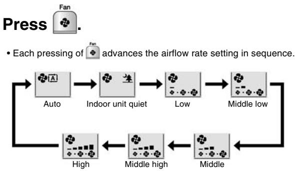
flowchart
graph TD
    A["Press Fan"] --> B["Auto"]
    B --> C["Indoor unit quiet"]
    C --> D["Low"]
    D --> E["Middle low"]
    E --> F["High"]
    F --> G["Middle high"]
    G --> H["Middle"]
    H --> I["End"]
    style A fill:#f9f,stroke:#333
    style I fill:#bbf,stroke:#333
- When the airflow is set to “生”, indoor unit quiet operation will start and the noise from the unit will become quieter.
- In indoor unit quiet operation, the airflow rate is set to a weak level.
- In DRY mode, the airflow rate setting is not variable.
NOTE
■ Note on the angles of the flaps
- The flaps swinging range depends on the operation. (See the figure.)
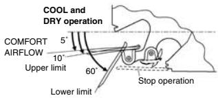
text_image
COOL and DRY operation COMFORT AIRFLOW 5° 10° Upper limit 60° Lower limit Stop operation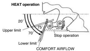
text_image
HEAT operation 20° Upper limit 75° 70° Lower limit Stop operation COMFORT AIRFLOW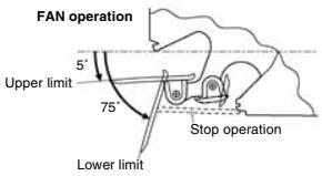
text_image
FAN operation Upper limit 5° 75° Stop operation Lower limit■ Note on airflow rate setting
- At smaller airflow rates, the cooling (heating) effect is also smaller.
- If the air conditioner is operated in COOL or DRY operation with the flaps kept stopped in the downward direction, the flaps will automatically start operating in approximately an hour in order to prevent dew condensation.

CAUTION
- Always use a remote controller to adjust the angles of the flaps. If you attempt to move it forcibly with hand when it is swinging, the mechanism may be broken.
- Be careful when adjusting the louvers.
Inside the air outlet, a fan is rotating at a high speed.
FTXS20/25K2V1B, CTXS15/35K2V1B

Adjusting the Airflow Direction and Rate
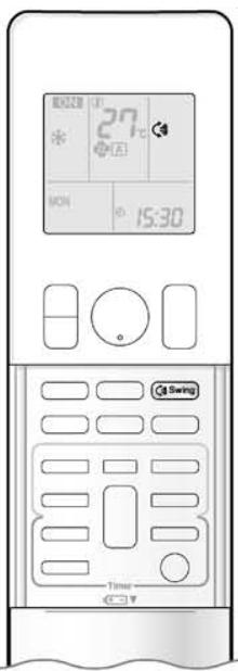
text_image
27°C MON 15:30 Switch TimeYou can adjust the airflow direction to increase your comfort.
■ To start auto swing
Upper and lower airflow direction
Press
Swing
- “C” is displayed on the LCD.
• The flap (horizontal blade) will begin to swing.
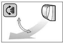
■ To set the flap at desired position
- This function is effective while flap is in auto swing mode.
Press Swing when the flap has reached the desired position.
- “C” disappears from the LCD.
■ To adjust the louvers at desired position
Hold the knob and move the louvers.
- You will find a knob on the left-side and the right-side blades.
- When the unit is installed in the corner of a room, the direction of the louvers (vertical blades) should be facing away from the wall.
If they face the wall, the wall will block off the wind, causing the cooling (or heating) efficiency to drop.
- If the flap is in the way, press Swing on the remote controller to move the flap out of the way and then adjust the louvers.
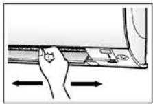
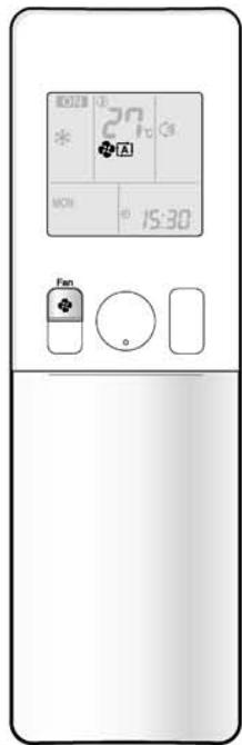
text_image
27 * + A MON 15:30 Fan o■ To adjust the airflow rate setting

• Each pressing of 📄 advances the airflow rate setting in sequence.
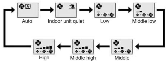
flowchart
graph TD
    A["Auto"] --> B["Indoor unit quiet"]
    B --> C["Low"]
    C --> D["Middle low"]
    D --> E["High"]
    E --> F["Middle high"]
    F --> G["Middle"]
- When the airflow is set to “♠”, indoor unit quiet operation will start and the noise from the unit will become quieter.
- In indoor unit quiet operation, the airflow rate is set to a weak level.
- If the temperature does not reach the desired point in the indoor unit quiet operation, change the airflow rate setting.
- In DRY mode, the airflow rate setting is not variable.
NOTE
■ Notes on the angles of the flap
- The flap swinging range depends on the operation. (See the figure.)
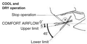
text_image
COOL and DRY operation Stop operation COMFORT AIRFLOW 0° Upper limit 5° 45° Lower limit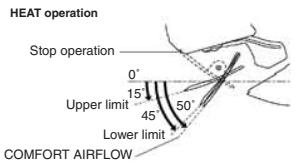
text_image
HEAT operation Stop operation 0° 15° Upper limit 45° 50° Lower limit COMFORT AIRFLOW
text_image
FAN operation Stop operation 0° 5° Upper limit 45° Lower limit- If the air conditioner is operated in COOL or DRY operation with the flap kept stopped in the downward direction, the flap will automatically start operating in approximately an hour in order to prevent dew condensation.
■ Note on airflow rate setting
- At smaller airflow rates, the cooling (heating) effect is also smaller.
CAUTION
• Always use a remote controller to adjust the angles of the flap. If you attempt to move the flap and louvers forcibly with hand when they are swinging, the mechanism may be broken.
- Be careful when adjusting the louvers.
Inside the air outlet, a fan is rotating at a high speed.
FVXG25/35/50K2V1B

Adjusting the Airflow Direction and Rate
You can adjust the airflow direction to increase your comfort.
■ To start auto swing
Upper and lower airflow direction
Press Swing.
- “ ⚪ ” is displayed on the LCD.
- The flap (horizontal blade) will begin to swing.
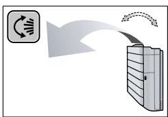
flowchart
graph TD
    A["Input"] --> B["Process"]
    B --> C["Output"]
    style A fill:#f9f,stroke:#333
    style C fill:#bbf,stroke:#333
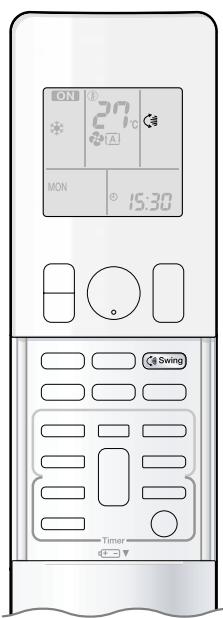
text_image
ON 27°C A MON 15:30 Swing Timer■ To set the flap at desired position
- This function is effective while flap is in auto swing mode.
Press Swing when the flap has reached the desired position.
- “ ⬇ ” disappears from the LCD.
■ To adjust the louvers at desired position
Hold the knob and move the louvers.
- You will find a knob on the left-side and the right-side blades.
- When the unit is installed in the corner of a room, the direction of the louvers (vertical blades) should be facing away from the wall.
If they face the wall, the wall will block off the wind, causing the cooling (or heating) efficiency to drop. - If the flap is in the way, press Swing on the remote controller to move the flap out of the way and then adjust the louvers.
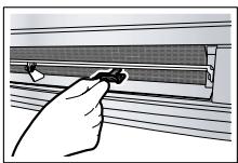

Adjusting the Airflow Direction and Rate
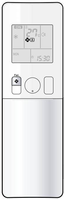
text_image
ON 27°C MON 15:30 Fan■ To adjust the airflow rate setting

• Each pressing of Fan advances the airflow rate setting in sequence.
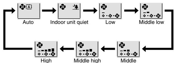
flowchart
graph TD
    A["Auto"] --> B["Indoor unit quiet"]
    B --> C["Low"]
    C --> D["Middle low"]
    D --> E["High"]
    E --> F["Middle high"]
    F --> G["Middle"]
- When the airflow is set to “▲”, indoor unit quiet operation will start and the noise from the unit will become quieter.
- In indoor unit quiet operation, the airflow rate is set to a weak level.
- In DRY or RADIANT operation, the airflow rate setting is not variable.
NOTE
■ Note on the angles of the flap
- The flap swinging range is the same by all operation. (See the figure.)

text_image
Upper limit 70° Lower limit 45° Stop operation■ Note on airflow rate setting
- At smaller airflow rates, the cooling (heating) effect is also smaller.
CAUTION
- Always use a remote controller to adjust the angles of the flap. If you attempt to move it forcibly with hand when it is swinging, the mechanism may be broken.
- Be careful when adjusting the louvers.
Inside the air outlet, a fan is rotating at a high speed.
2.1.8 COMFORT AIRFLOW Operation

COMFORT AIRFLOW Operation

text_image
ON 27°C MON 15:30 Comfort TimerThe flow of air will be in the upward direction while in COOL operation and in the downward direction while in HEAT operation, which will provide a comfortable wind that will not come in direct contact with people.
■ To start COMFORT AIRFLOW operation

- “💡” is displayed on the LCD.
- Airflow rate is set to Auto. COOL/DRY: The flap will go up. HEAT: The flap will go down.
■ To cancel COMFORT AIRFLOW operation

- The flaps will return to the memory position from before COMFORT AIRFLOW operation.
- “💡” disappears from the LCD.
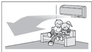
natural_image
Illustration of two children sitting on a bench with an air conditioner unit above (no text or symbols)COOL operation
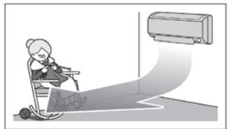
natural_image
Illustration of a person using a VR headset to reach a wall-mounted air conditioner (no text or symbols present)HEAT operation
NOTE
■ Notes on COMFORT AIRFLOW operation
- The flap position will change, preventing air from blowing directly on the occupants of the room.
- POWERFUL operation and COMFORT AIRFLOW operation cannot be used at the same time.
Priority is given to the function of whichever button is pressed last.
The airflow rate will be set to Auto. If the upper and lower airflow direction is selected, the COMFORT AIRFLOW operation will be canceled.
2.1.9 INTELLIGENT EYE Operation

INTELLIGENT EYE Operation
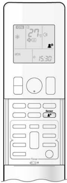
text_image
27°C MON 15:30 Sensor Time“INTELLIGENT EYE” is the infrared sensor which detects the human movement. If nobody in the room for more than 20 minutes, the operation automatically changes to energy saving operation.
■ To start INTELLIGENT EYE operation

- “” is displayed on the LCD.
- The INTELLIGENT EYE lamp lights green.
Display
■ To cancel INTELLIGENT EYE operation

• “ ” disappears from the LCD.
- The INTELLIGENT EYE lamp goes off.

INTELLIGENT EYE Operation
[Example]
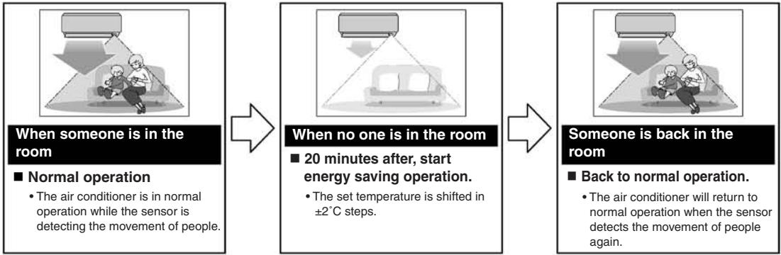
flowchart
graph LR
    A["When someone is in the room\n■ Normal operation\n• The air conditioner is in normal operation while the sensor is detecting the movement of people."] --> B["When no one is in the room\n■ 20 minutes after, start energy saving operation.\n• The set temperature is shifted in ±2°C steps."]
    B --> C["Someone is back in the room\n■ Back to normal operation.\n• The air conditioner will return to normal operation when the sensor detects the movement of people again."]
INTELLIGENT EYE operation is useful for energy saving
■ Energy saving operation
- If no presence detected in the room for 20 minutes, the energy saving operation will start.
- This operation changes the temperature -2^ in HEAT / +2^ in COOL / +1^ in DRY operation from set temperature.
When the room temperature exceeds 30^ C, the operation changes the temperature +1^ C in COOL / +1^ C in DRY operation from set temperature. - This operation decreases the airflow rate slightly in FAN operation only.
NOTE
■ Notes on INTELLIGENT EYE operation
- Application range is as follows.
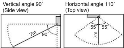
text_image
Vertical angle 90° (Side view) 7m 90° Horizontal angle 110° (Top view) 55° 55° 7m- Sensor may not detect moving objects further than 7m away. (Check the application range.)
- Sensor detection sensitivity changes according to indoor unit location, the speed of passersby, temperature range, etc.
- The sensor also mistakenly detects pets, sunlight, fluttering curtains and light reflected off of mirrors as passersby.
• INTELLIGENT EYE operation will not go on during POWERFUL operation. - NIGHT SET mode will not go on during use of INTELLIGENT EYE operation.

CAUTION
- Do not place large objects near the sensor.
Also keep heating units or humidifiers outside the sensor's detection area. This sensor can detect undesirable objects. - Do not hit or violently push the INTELLIGENT EYE sensor. This can lead to damage and malfunction.
2.1.10 POWERFUL Operation
FTXG25/35/50JV1BW(A), FTXS20/25K2V1B, CTXS15/35K2V1B

POWERFUL Operation
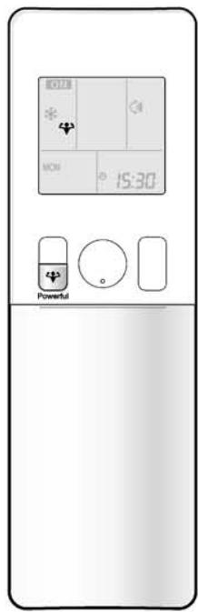
text_image
0:12 MOS 15:30 PowerfulPOWERFUL operation quickly maximizes the cooling (heating) effect in any operation modes. You can get the maximum capacity.
■ To start POWERFUL operation
Press Powerful during operation.
- POWERFUL operation ends in 20 minutes. Then the system automatically operates again with the previous settings which were used before POWERFUL operation.
- “ ” is displayed on the LCD.
■ To cancel POWERFUL operation
Press Powerful again.
- “♥” disappears from the LCD.
[Example]
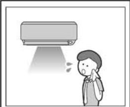
natural_image
Illustration of a person reacting to a small electric fan or air conditioner (no text or symbols present)■ Normal operation
- When you want to get the cooling effect quickly, start the POWERFUL operation.
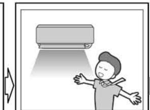
natural_image
Illustration of a person receiving air conditioner lighting from a wall-mounted air conditioner (no text or symbols)■ POWERFUL operation
- POWERFUL operation will work for 20 minutes.
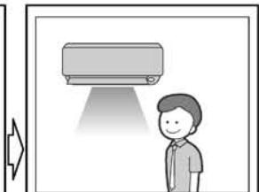
natural_image
Illustration of a person standing next to a wall-mounted air conditioner unit with a light beam (no text or symbols)■ Back to normal operation
NOTE
■ Notes on POWERFUL operation
- When using POWERFUL operation, there are some functions which are not available.
-
POWERFUL operation cannot be used together with ECONO, COMFORT AIRFLOW or OUTDOOR UNIT QUIET operation.
Priority is given to the function of whichever button is pressed last. -
POWERFUL operation can only be set when the unit is running. Pressing ⏻ causes the settings to be canceled, and the “♥” disappears from the LCD.
- POWERFUL operation will not increase the capacity of the air conditioner if the air conditioner is already in operation with its maximum capacity demonstrated.
• In COOL and HEAT operation
To maximize the cooling (heating) effect, the capacity of outdoor unit is increased and the airflow rate is fixed to the maximum setting. The temperature and airflow settings are not variable.
- In DRY operation
The temperature setting is lowered by 2.5^ C and the airflow rate is slightly increased.
- In FAN operation
The airflow rate is fixed to the maximum setting.
- In AUTO operation
To maximize the cooling (heating) effect, the capacity of outdoor unit is increased and the airflow rate is fixed to the maximum setting.
FVXG25/35/50K2V1B

POWERFUL Operation
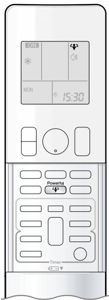
text_image
ON MON 15:30 Powerful TimerPOWERFUL operation quickly maximises the cooling (heating) effect in any operation mode. You can get the maximum capacity.
■ To start POWERFUL operation
Press Powerful during operation.
- POWERFUL operation ends in 20 minutes. Then the system automatically operates again with the previous settings which were used before POWERFUL operation.
- “ ” is displayed on the LCD.
■ To cancel POWERFUL operation
Press Powerful again.
- “▼” disappears from the LCD.
[Example]
natural_image
Illustration of a person reacting to a large industrial machine emitting smoke (no text or symbols present)■ Normal operation
- When you want to get the cooling effect quickly, start the POWERFUL operation.

natural_image
Illustration of a person standing with arms outstretched, standing beside a stack of books (no text or symbols visible)■ POWERFUL operation
- POWERFUL operation will work for 20 minutes.

natural_image
Illustration of a person standing beside a printer with a paper airplane in the background (no text or symbols)■Back to normal operation
NOTE
■ Notes on POWERFUL operation
- When using POWERFUL operation, there are some functions which are not available.
- POWERFUL operation cannot be used together with RADIANT2, ECONO or OUTDOOR UNIT QUIET operation.
Priority is given to the function of whichever button is pressed last.
- POWERFUL operation can only be set when the unit is running. Pressing ⏻ causes the settings to be canceled, and the “♥” disappears from the LCD.
- POWERFUL operation will not increase the capacity of the air conditioner if the air conditioner is already in operation with its maximum capacity demonstrated.
• In COOL, HEAT and RADIANT1 operation
To maximise the cooling (heating) effect, the capacity of outdoor unit is increased and the airflow rate is fixed to the maximum setting. The temperature and airflow settings are not variable.
- In DRY operation
The temperature setting is lowered by 2.5°C and the airflow rate is slightly increased.
• In FAN operation
The airflow rate is fixed to the maximum setting.
• In AUTO operation
To maximise the cooling (heating) effect, the capacity of outdoor unit is increased and the airflow rate is fixed to the maximum setting.
2.1.11 OUTDOOR UNIT QUIET Operation

OUTDOOR UNIT QUIET Operation
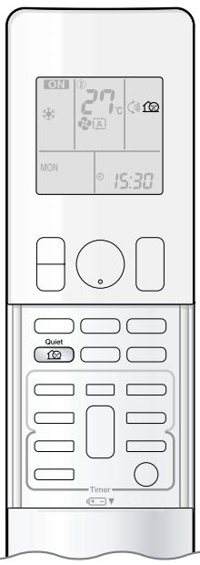
text_image
ON 27°C MON 15:30 Quiet TimerOUTDOOR UNIT QUIET operation lowers the noise level of the outdoor unit by changing the frequency and fan speed on the outdoor unit. This function is convenient during the night.
■ To start OUTDOOR UNIT QUIET operation

- “ 🔍 ” is displayed on the LCD.
■ To cancel OUTDOOR UNIT QUIET operation

- “ 🔒 ” disappears from the LCD.
[Example] Using the OUTDOOR UNIT QUIET operation during the night.
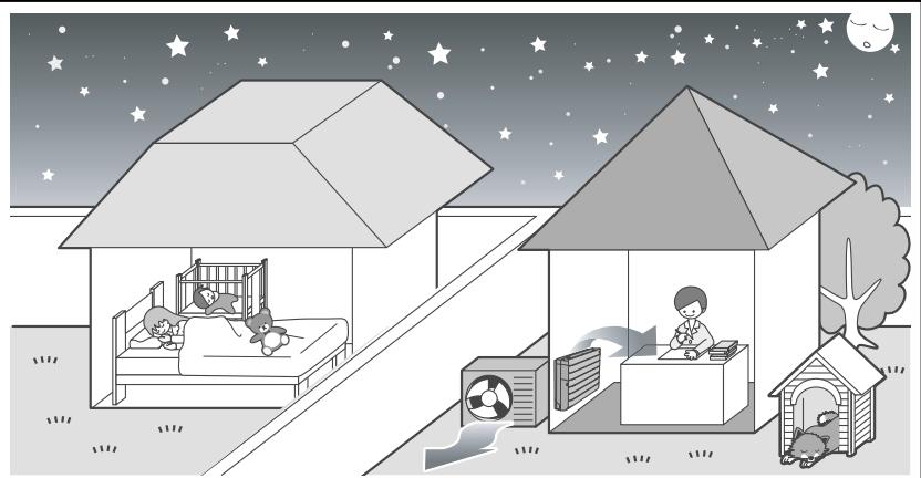
natural_image
Illustration of a night scene with two houses, a bed, and children in the sky (no text or symbols)- The noise level of the outdoor unit will be lower. This is convenient when you need to consideration for your neighbourhood.
NOTE
■ Notes on OUTDOOR UNIT QUIET operation
- This function is available in COOL, HEAT, and AUTO operation.
This is not available in RADIANT, FAN and DRY operation. - POWERFUL operation and OUTDOOR UNIT QUIET operation cannot be used at the same time.
Priority is given to the function of whichever button is pressed last.
• Even the operation is stopped using the remote controller or the indoor unit ON/OFF switch when using OUTDOOR UNIT QUIET operation,
“①” will remain on the remote controller display. - OUTDOOR UNIT QUIET operation will drop neither the frequency nor fan speed if they have been already dropped low enough.
2.1.12 ECONO Operation

ECONO Operation
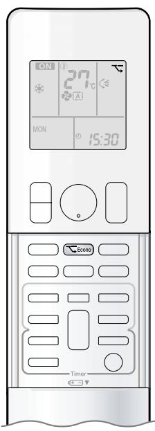
text_image
ON 27°C MON 15:30 Ecore TimerECONO operation is a function which enables efficient operation by limiting the maximum power consumption value. This function is useful for cases in which attention should be paid to ensure a circuit breaker will not trip when the product runs alongside other appliances.
■ To start ECONO operation
Press Econo during operation.
- “ ” is displayed on the LCD.
■ To cancel ECONO operation
Press Econo again.
- “ ↘ ” disappears from the LCD.
[Example]
Normal operation
![DAIKIN FVXM-F/FVXS-F - [Example] - 1](/content/2020/11/206417/images/7f3c7a96c340144ea13e55aaf2a860588662a90f9c75271c277876c6c884402b.jpg)
natural_image
Illustration of a person sleeping under a lamp, with thought bubbles showing household items like a lamp and a washing machine (no text or symbols)- In case the air conditioner and other appliances which require high power consumption are used at same time, a circuit breaker may trip if the air conditioner operate with its maximum capacity.
ECONO operation
![DAIKIN FVXM-F/FVXS-F - [Example] - 2](/content/2020/11/206417/images/7c09ec5611de9daa8900ae12f7bcb46eb31f598c4f1480aa2b43d06146c9f6b9.jpg)
natural_image
Illustration of a person reacting to printing and cleaning items including a printer, cleaning tools, and washing machine (no text or symbols)- The maximum power consumption of the air conditioner is limited by using ECONO operation.
The circuit breaker will hardly trip even if the air conditioner and other appliances are used at same time.
![DAIKIN FVXM-F/FVXS-F - [Example] - 3](/content/2020/11/206417/images/22228a8c46040bbc46a9a32954295151f05c23875e04ab3e951d68238e3af95b.jpg)
line
| Time | Running current and power consumption | |------|----------------------------------------| | 0 | Maximum during normal operation | | 1 | Normal operation | | 2 | ECONO operation | | 3 | Maximum during ECONO operation |From start up until set temperature is reached
- This diagram is a representation for illustrative purposes only.
The maximum running current and power consumption of the air conditioner in ECONO operation vary with the connecting outdoor unit.
NOTE
■ Notes on ECONO operation
- ECONO operation can only be set when the unit is running. Pressing ⏻ causes the settings to be canceled, and the “↖” disappears from the LCD.
- ECONO operation is a function which enables efficient operation by limiting the power consumption of the outdoor unit (operating frequency).
- ECONO operation functions in AUTO, COOL, DRY, and HEAT operation.
This is not available in RADIANT and FAN operation. - POWERFUL operation and ECONO operation cannot be used at the same time.
Priority is given to the function of whichever button is pressed last. - If the level of power consumption is already low, ECONO operation will not drop the power consumption.
2.1.13 OFF TIMER Operation
FTXG25/35/50JV1BW(A)

OFF TIMER Operation
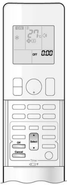
text_image
27°C OFF 0:00 OFF Select Cancel TimerTimer functions are useful for automatically switching the air conditioner on or off at night or in the morning. You can also use OFF TIMER and ON TIMER in combination.
■ To use OFF TIMER operation
- Check that the clock is correct. If not, set the clock to the present time.
1. Press

- “0:00” is displayed on the LCD. - “OFF” blinks.
- “④” and day of the week disappear from the LCD.
2. Press Select until the time setting reaches the point you like.
• Each pressing of either button increases or decreases the time setting by 10 minutes. Holding down either button changes the time setting rapidly.
3. Press Off again.
- “OFF” and setting time are displayed on the LCD. - The multi-monitor lamp blinks twice. The TIMER lamp periodically lights orange.

Display
■ To cancel OFF TIMER operation
Press

- “OFF” and setting time disappear from the LCD.
- “💡” and day of the week are displayed on the LCD.
NOTE
■ Notes on TIMER operation
- When TIMER is set, the present time is not displayed.
- Once you set ON/OFF TIMER, the time setting is kept in the memory. The memory is canceled when remote controller batteries are replaced.
- When operating the unit via the ON/OFF TIMER, the actual length of operation may vary from the time entered by the user. (Maximum approx. 10 minutes)
■ NIGHT SET mode
- When the OFF TIMER is set, the air conditioner automatically adjusts the temperature setting (0.5°C up in COOL, 2.0°C down in HEAT) to prevent excessive cooling (heating) for your pleasant sleep.
FTXS20/25K2V1B, CTXS15/35K2V1B

OFF TIMER Operation
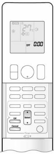
text_image
27°C OFF 0:00 Off Select Cancel TimeTimer functions are useful for automatically switching the air conditioner on or off at night or in the morning. You can also use OFF TIMER and ON TIMER in combination.
■ To use OFF TIMER operation
- Check that the clock is correct. If not, set the clock to the present time.
1. Press Off.
- “0:00” is displayed on the LCD. - “OFF” blinks.
- “💡” and day of the week disappear from the LCD.
2. Press Select until the time setting reaches the point you like.
• Each pressing of either button increases or decreases the time setting by 10 minutes. Holding down either button changes the time setting rapidly.
3. Press off again.
- “OFF” and setting time are displayed on the LCD. - The TIMER lamp lights yellow.
Display
■ To cancel OFF TIMER operation
Press Cancel.
- "OFF" and setting time disappear from the LCD.
- “💡” and day of the week are displayed on the LCD.
• The TIMER lamp goes off.
NOTE
■ Notes on TIMER operation
- When TIMER is set, the present time is not displayed.
- Once you set ON/OFF TIMER, the time setting is kept in the memory. The memory is canceled when remote controller batteries are replaced.
- When operating the unit via the ON/OFF TIMER, the actual length of operation may vary from the time entered by the user. (Maximum approx. 10 minutes)
■ NIGHT SET mode
- When the OFF TIMER is set, the air conditioner automatically adjusts the temperature setting (0.5°C up in COOL, 2.0°C down in HEAT) to prevent excessive cooling (heating) for your pleasant sleep.
FVXG25/35/50K2V1B

OFF TIMER Operation
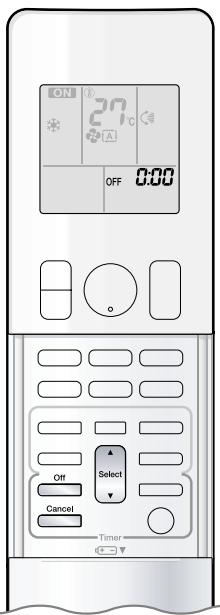
text_image
ON 27°C OFF 0:00 Off Select Cancel TimerTimer functions are useful for automatically switching the air conditioner on or off at night or in the morning. You can also use OFF TIMER and ON TIMER in combination.
■ To use OFF TIMER operation
- Check that the clock is correct. If not, set the clock to the present time.
1. Press Off.
- “0:00” is displayed on the LCD. - “OFF” blinks.
- “④” and day of the week disappear from the LCD.
2. Press Select until the time setting reaches the point you like.
• Each pressing of either button increases or decreases the time setting by 10 minutes. Holding down either button changes the time setting rapidly.
3. Press Off again.
- “OFF” and setting time are displayed on the LCD. - The OPERATION lamp blinks and the TIMER lamp lights yellow.

Display
■ To cancel OFF TIMER operation
Press Cancel.
- “OFF” and setting time disappear from the LCD.
- “④” and day of the week are displayed on the LCD.
NOTE
■ Notes on TIMER operation
- When TIMER is set, the present time is not displayed.
- Once you set ON/OFF TIMER, the time setting is kept in the memory. The memory is canceled when remote controller batteries are replaced.
- When operating the unit via the ON/OFF TIMER, the actual length of operation may vary from the time entered by the user. (Maximum approximately 10 minutes)
■ NIGHT SET mode
- When the OFF TIMER is set, the air conditioner automatically adjusts the temperature setting (0.5°C up in COOL, 2.0°C down in HEAT) to prevent excessive cooling (heating) for your pleasant sleep.
2.1.14 ON TIMER Operation
FTXG25/35/50JV1BW(A)

ON TIMER Operation
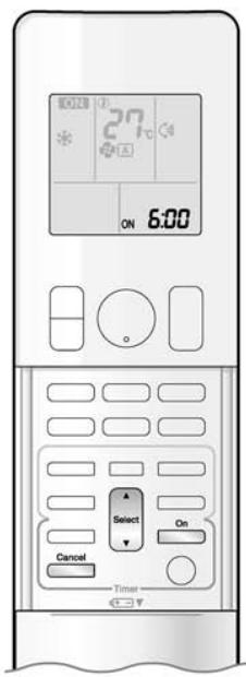
text_image
6:00 27°C ON 6:00 Select On Cancel Timer■ To use ON TIMER operation
- Check that the clock is correct. If not, set the clock to the present time.
1. Press On.
- “6:00” is displayed on the LCD. - “ON” blinks.
- “④” and day of the week disappear from the LCD.
2. Press Select until the time setting reaches the point you like.
• Each pressing of either button increases or decreases the time setting by 10 minutes. Holding down either button changes the setting rapidly.
3. Press On again.
- “ON” and setting time are displayed on the LCD. - The multi-monitor lamp blinks twice. The TIMER lamp periodically lights orange.
■ To cancel ON TIMER operation

- “ON” and setting time disappear from the LCD. - “⊕” and day of the week are displayed on the LCD.
■ To combine ON TIMER and OFF TIMER
- A sample setting for combining the 2 timers is shown below.
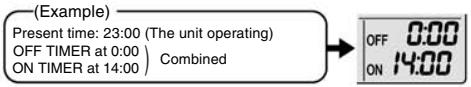
text_image
(Example) Present time: 23:00 (The unit operating) OFF TIMER at 0:00 ON TIMER at 14:00) Combined OFF 0:00 ON 14:00NOTE
■ In the following cases, set the timer again.
• After a breaker has turned off.
• After a power failure.
• After replacing batteries in the remote controller.
FTXS20/25K2V1B, CTXS15/35K2V1B

ON TIMER Operation
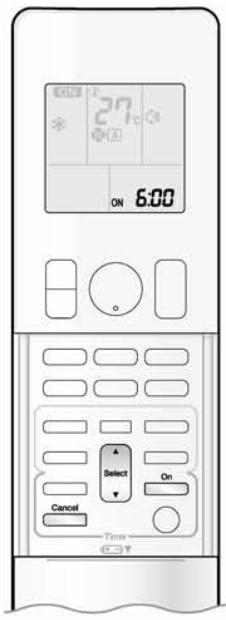
text_image
ON 6:00 27°C Select Cancel On Time OFF■ To use ON TIMER operation
- Check that the clock is correct. If not, set the clock to the present time.
1. Press On.
- “6:00” is displayed on the LCD. - “ON” blinks.
- “💡” and day of the week disappear from the LCD.
2. Press Select until the time setting reaches the point you like.
• Each pressing of either button increases or decreases the time setting by 10 minutes. Holding down either button changes the setting rapidly.
3. Press □ on again.
- “ON” and setting time are displayed on the LCD. - The TIMER lamp lights yellow.
Display
■ To cancel ON TIMER operation
Press Cancel.
- “ON” and setting time disappear from the LCD.
- “💡” and day of the week are displayed on the LCD.
• The TIMER lamp goes off.
■ To combine ON TIMER and OFF TIMER
- A sample setting for combining the 2 timers is shown below.
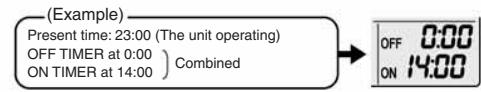
text_image
(Example) Present time: 23:00 (The unit operating) OFF TIMER at 0:00 ON TIMER at 14:00) Combined OFF 0:00 ON 14:00NOTE
■ In the following cases, set the timer again.
• After a breaker has turned off.
• After a power failure.
• After replacing batteries in the remote controller.
FVXG25/35/50K2V1B

ON TIMER Operation
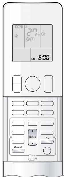
text_image
ON 27°C ON 6:00 Select Cancel On Timer■ To use ON TIMER operation
- Check that the clock is correct. If not, set the clock to the present time.
1. Press On.
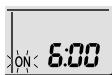
- “6:00” is displayed on the LCD. - “ON” blinks.
- “④” and day of the week disappear from the LCD.
2. Press Select until the time setting reaches the point you like.
• Each pressing of either button increases or decreases the time setting by 10 minutes. Holding down either button changes the time setting rapidly.
3. Press On again.
- “ON” and setting time are displayed on the LCD. - The OPERATION lamp blinks and the TIMER lamp lights yellow.

Display
■ To cancel ON TIMER operation
Press Cancel.
- “ON” and setting time disappear from the LCD.
- “ ⏻ ” and day of the week are displayed on the LCD.
■ To combine ON TIMER and OFF TIMER
- A sample setting for combining the 2 timers is shown below.
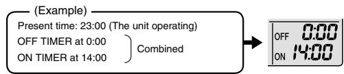
text_image
(Example) Present time: 23:00 (The unit operating) OFF TIMER at 0:00 ON TIMER at 14:00) Combined → OFF 0:00 ON 14:00NOTE
■ In the following cases, set the timer again.
• After a breaker has turned off.
• After a power failure.
• After replacing batteries in the remote controller.
2.1.15 WEEKLY TIMER Operation

WEEKLY TIMER Operation
Up to 4 timer settings can be saved for each day of the week. It is convenient if the WEEKLY TIMER is set according to the family's life style.
■ Using in these cases of WEEKLY TIMER
[Example] The same timer settings are made for the week from Monday through Friday while different timer settings are made for the weekend.
| [Monday] | Make timer settings up to programs 1-4.P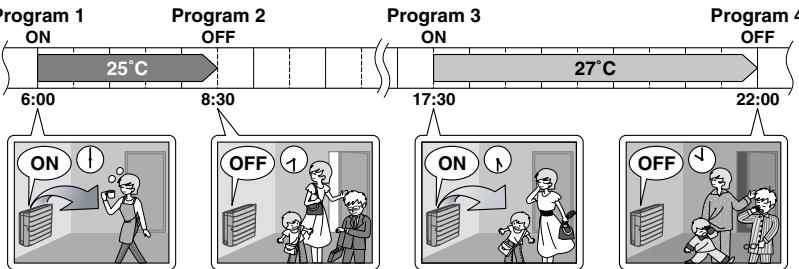 |
| [Tuesday] to [Friday] | Use the copy mode to make settings for Tuesday to Friday, because these settings are the same as those for Monday.| 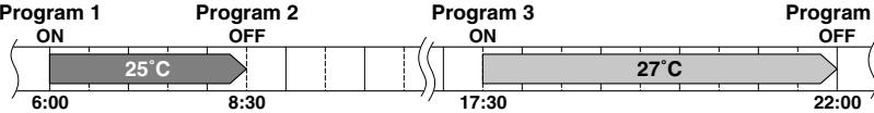 4 4 |
| [Saturday] | No timer settings |
| [Sunday] | Make timer settings up to programs 1-4.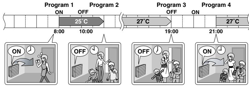 |
- Up to 4 reservations per day and 28 reservations per week can be set in the WEEKLY TIMER. The effective use of the copy mode ensures ease of making reservations.
- The use of ON-ON-ON-ON settings, for example, makes it possible to schedule operating mode and set temperature changes. Furthermore, by using OFF-OFF-OFF-OFF settings, only the turn off time of each day can be set. This will turn off the air conditioner automatically if the user forgets to turn it off.
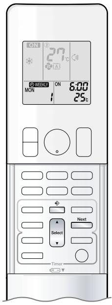
text_image
ON 27°C ON 6:00 MON 25°C Timer Next Select■To use WEEKLY TIMER operation
Setting mode
- Make sure the day of the week and time are set. If not, set the day of the week and time.
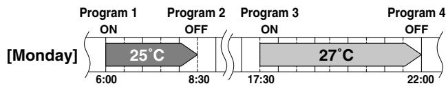
line
| Time Period | Phase | Temperature | | ----------- | --------- | ----------- | | [Monday] | ON | - | | 6:00 | OFF | 25°C | | 8:30 | OFF | - | | 17:30 | ON | - | | 22:00 | OFF | 27°C |Setting Displays
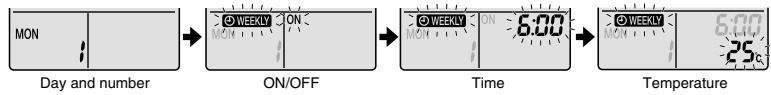
flowchart
graph LR
    A["MON"] --> B["ON/OFF"]
    B --> C["Time"]
    C --> D["Temperature"]
1. Press
- The day of the week and the reservation number of the current day will be displayed.
- 1 to 4 settings can be made per day
2. Press Select to select the desired day of the week and reservation number.
- Pressing ▲ Select changes the reservation number and the day of the week.
3. Press Next .
- The day of the week and reservation number will be set.
- “ ⏻ WEEKLY ” and “ ON ” blink.
4. Press Select to select the desired mode.
- Pressing Select changes "ON" or "OFF" setting in sequence.
Pressing ▲ alternates the following items appearing on the LCD in rotational sequence.
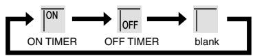
- In case the reservation has already been set, selecting “blank” deletes the reservation.
- Go to step 9 if "blank" is selected.
- To return to the day of the week and reservation number setting, press Back.
5. Press Next .
- The ON/OFF TIMER mode will be set.
- “ ⏻ WEEKLY ” and the time blink.

WEEKLY TIMER Operation
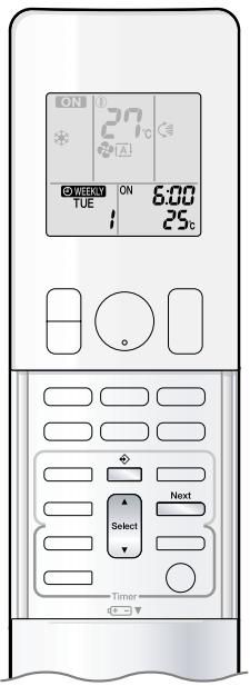
text_image
ON ON 6:00 TUE 25°C Next Select Timer6. Press Select to select the desired time.
- The time can be set between 0:00 and 23:50 in 10 minute intervals.
- To return to the ON/OFF TIMER mode setting, press Back.
- Go to step 9 when setting the OFF TIMER.
7. Press Next .
- The time will be set.
- “ ⏻ WEEKLY ” and the temperature blink.

8. Press Select to select the desired temperature.
- The temperature can be set between 10^ and 32^ .
COOL or AUTO: The unit operates at 18^ C even if it is set at 10 to 17^ C.
HEAT or AUTO: The unit operates at 30^ C even if it is set at 31 to 32^ C. - To return to the time setting, press Back
- The set temperature is only displayed when the mode setting is on.
9. Press Next .
- Be sure to direct the remote controller toward the indoor unit and check for a receiving tone and flashing the OPERATION lamp.
- The temperature is set while in ON TIMER operation, and the time is set while in OFF TIMER operation.
- The next reservation screen will appear.
- To continue further settings, repeat the procedure from step 4.
- The TIMER lamp lights yellow.

Display
10. Press ☐ to complete the setting.
- “ Ⓧ WEEKLY ” is displayed on the LCD and WEEKLY TIMER operation is activated.
- A reservation made once can be easily copied and the same settings used for another day of the week. Refer to copy mode.
NOTE
■ Notes on WEEKLY TIMER operation
- Do not forget to set the clock on the remote controller first.
- The day of the week, ON/OFF TIMER mode, time and set temperature (only for ON TIMER mode) can be set with WEEKLY TIMER.
Other settings for ON TIMER are based on the settings just before the operation. - Both WEEKLY TIMER and ON/OFF TIMER operation cannot be used at the same time. The ON/OFF TIMER operation has priority if it is set while WEEKLY TIMER is still active. The WEEKLY TIMER will go into standby state, and “WEEKLY” will disappear from the LCD. When ON/OFF TIMER is up, the WEEKLY TIMER will automatically become active.
- Shutting the breaker off, power failure, and other similar events will render operation of the indoor unit's internal clock inaccurate. Reset the clock.
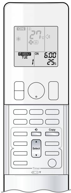
text_image
ON 27°C A WEEKLY TUE ON 6:00 25°C Copy Select TimerCopy mode
- A reservation made once can be copied to another day of the week. The whole reservation of the selected day of the week will be copied.
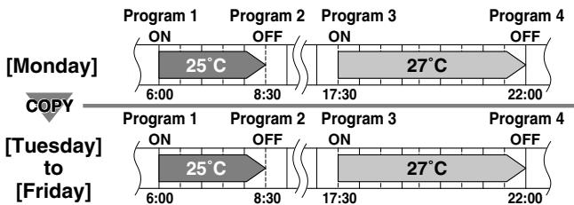
line
| Time Period | Program 1 ON | Program 2 OFF | Program 3 ON | Program 4 OFF | | --------------- | ------------ | ------------- | ------------ | ------------- | | [Monday] | 25°C | - | - | - | | 6:00 | - | - | - | - | | 8:30 | - | - | - | - | | 17:30 | - | - | - | - | | 22:00 | - | - | - | - | | [Tuesday] to [Friday] | 25°C | - | - | - | | 6:00 | - | - | - | - | | 8:30 | - | - | - | - | | 17:30 | - | - | - | - | | 22:00 | - | - | - | - |Setting Displays
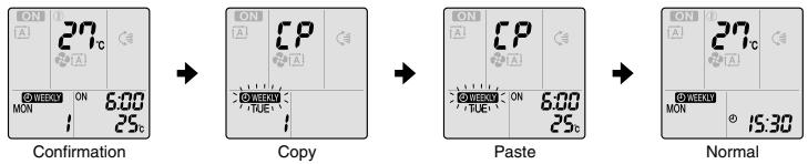
text_image
ON A 27c ON MON ON 6:00 25c Confirmation ON A CP ON TUE1 ON 6:00 25c Copy ON A CP ON TUE1 ON 6:00 25c Paste ON A CP ON TUE1 ON 6:00 25c Normal ON A 27c ON MON ON 15:30- Press
- Press Select to confirm the day of the week to be copied.
- Press Copy
- The whole reservation of the selected day of the week will be copied.
- Press Select to select the destination day of the week.
-
Press Copy .
-
Be sure to direct the remote controller toward the indoor unit and check for a receiving tone and flashing the OPERATION lamp.
- The reservation will be copied to the selected day of the week. The whole reservation of the selected day of the week will be copied.
-
To continue copying the settings to other days of the week, repeat step 4 and step 5.
-
Press ☐ to complete the setting.
- “ Ⓧ WEEKLY ” is displayed on the LCD and WEEKLY TIMER operation is activated.
NOTE
■ Note on copy mode
- The entire reservation of the source day of the week is copied in the copy mode.
In the case of making a reservation change for any day of the week individually after copying the content of weekly reservations, press and change the settings in the steps of setting mode.


WEEKLY TIMER Operation
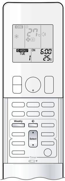
text_image
ON 27°C OFF/VEEY ON 6:00 TUE 25°C Weekly Select Timer■ Confirming a reservation
- The reservation can be confirmed.
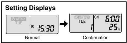
text_image
Setting Displays © WEEKLY TUE 15:30 Normal © WEEKLY TUE ON 6:00 25°C Confirmation- Press
- The day of the week and the reservation number of the current day will be displayed.
- Press Select to select the day of the week and the reservation number to be confirmed.
- Pressing Select displays the reservation details.
- To change the confirmed reserved settings, select the reservation number and press Next.
The mode is switched to setting mode. Go to setting mode step 2.
- Press ☐ to exit confirming mode.
■ To deactivate WEEKLY TIMER operation
Press ☐ while “ Ⓧ WEEKLY ” is displayed on the LCD.
- The “ Ⓧ WEEKLY ” will disappear from the LCD.
- The TIMER lamp goes off.
- To reactivate the WEEKLY TIMER operation, press □ again.
- If a reservation deactivated with ____ is activated once again, the last reservation mode will be used.
CAUTION
- If not all the reservation settings are reflected, deactivate the WEEKLY TIMER operation once. Then press again to reactivate the WEEKLY TIMER operation.
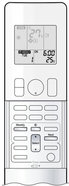
text_image
ON 27°C A 6:00 TUE ON 25°C Weekly Select Next Timer■ To delete reservations
The individual reservation
1. Press
- The day of the week and the reservation number will be displayed.
2. Press Select to select the day of the week and the reservation number to be deleted.
3. Press Next.
- “WEEKLY” and “ON” or “OFF” blink.
4. Press Select and select "blank".
- Pressing Select changes ON/OFF TIMER mode.
Pressing ▲ alternates the following items appearing on the LCD in rotational sequence.
- The reservation will be no setting with selecting "blank".
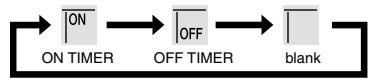
5. Press Next.
- The selected reservation will be deleted.
6. Press
- If there are still other reservations, WEEKLY TIMER operation will be activated.
The reservations for each day of the week
- This function can be used for deleting reservations for each day of the week.
- It can be used while confirming or setting reservations.
1. Press Select to select the day of the week to be deleted.
2. Hold Weekly for 5 seconds.
- The reservation of the selected day of the week will be deleted.
All reservations
Weekly
Hold □ for 5 seconds while normal display.
- Be sure to direct the remote controller toward the indoor unit and check for a receiving tone.
- This operation is not effective while WEEKLY TIMER is being set.
- All reservations will be deleted.
2.1.16 Note for Multi System
Note for Multi System
Multi system has one outdoor unit connected to multiple indoor units.
■ Selecting the operation mode
With the priority room setting present but inactive or not present.
When more than one indoor unit is operating, priority is given to the first unit that was turned on.
In this case, set the units that are turned on later to the same operation mode as the first unit.
Otherwise, they will enter the standby state, and the OPERATION lamp will flash: this does not indicate malfunction.
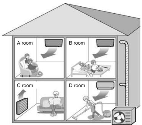
text_image
A room B room C room D roomOutdoor unit
NOTE
■ Notes on operation mode for multi system
- COOL, DRY and FAN operation may be used at the same time.
- HEAT and RADIANT operation may be used at the same time.
- AUTO operation automatically selects COOL operation or HEAT operation based on the room temperature.
Therefore, AUTO operation is available when selecting the same operation mode as that of the room with the first unit to be turned on.
CAUTION
- Normally, the operation mode in the room where the unit is first run is given priority, but the following situations are exceptions, so please keep this in mind.
If the operation mode of the first room is FAN operation, then using HEAT and RADIANT operation in any room after this will give priority to HEAT and RADIANT operation. In this situation, the air conditioner running in FAN operation will go on standby, and the OPERATION lamp will flash. When the RADIANT operation starts when the FAN operation is used in another room, the FAN operation is switched to the HEAT operation.
With the priority room setting active.
Refer to priority room setting on the next page.
■ NIGHT QUIET mode (Available only for COOL operation)
NIGHT QUIET mode requires initial programming during installation. Please consult your retailer or dealer for assistance.
NIGHT QUIET mode reduces the operation noise of the outdoor unit during the nighttime hours to prevent annoyance to neighbours.
- The NIGHT QUIET mode is activated when the temperature drops 5^ or more below the highest temperature recorded that day. Therefore, when the temperature difference is less than 5^ , this function will not be activated.
- NIGHT QUIET mode reduces slightly the cooling efficiency of the unit.
■ OUTDOOR UNIT QUIET operation
Refer to OUTDOOR UNIT QUIET operation.
With the priority room setting present but inactive or not present.
When using the OUTDOOR UNIT QUIET operation feature with the multi system, set all indoor units to OUTDOOR UNIT QUIET operation using their remote controllers.
When clearing OUTDOOR UNIT QUIET operation, clear one of the operating indoor units using their remote controller. However OUTDOOR UNIT QUIET operation display remains on the remote controller for other rooms.
We recommend you release all rooms using their remote controllers.
With the priority room setting active.
Refer to priority room setting on the next page.
COOL/HEAT mode lock
The COOL/HEAT mode lock requires initial programming during installation. Please consult your authorised dealer for assistance. The COOL/HEAT mode lock sets the unit forcibly to either COOL or HEAT operation. This function is convenient when you wish to set all indoor units connected to the multi system to the same operation mode. During the COOL mode, the DRY operation can also be used. During the HEAT mode, the RADIANT operation can also be used.
NOTE
- The COOL/HEAT mode lock cannot be activated together with the priority room setting.
■ Priority room setting
The priority room setting requires initial programming during installation. Please consult your authorised dealer for assistance.
The room designated as the priority room takes priority in the following situations.
Operation mode priority
- As the operation mode of the priority room takes precedence, the user can select a different operation mode from other rooms.
[Example]
- Room A is the priority room in the examples.
When COOL operation is selected in room A while operating the following modes in room B, C and D:
| Operation mode in room B, C and D | Status of room B, C and D when the unit in room A is in COOL operation |
| COOL or DRY or FAN | Current operation mode maintained |
| HEAT and RADIANT | The unit enters standby mode. Operation resumes when the room A unit stops operating. |
| AUTO | If the unit is set to COOL operation, it continues. If the unit is set to HEAT operation, it enters standby mode. Operation resumes when the room A unit stops operating. |
Priority when POWERFUL operation is used
[Example]
- Room A is the priority room in the examples. The indoor units in rooms A, B, C and D are all operating. If the unit in room A enters POWERFUL operation, operation capacity will be concentrated in room A. In such a case, the cooling (heating) efficiency of the units in room B, C and D may be slightly reduced.
Priority when using OUTDOOR UNIT QUIET operation
[Example]
- Room A is the priority room in the examples. Just by setting the unit in room A to QUIET operation, the air conditioner starts OUTDOOR UNIT QUIET operation. You don't have to set all the operated indoor units to QUIET operation.
2.1.17 Quick Reference
FTXG25/35/50JV1BW(A)
Quick Reference
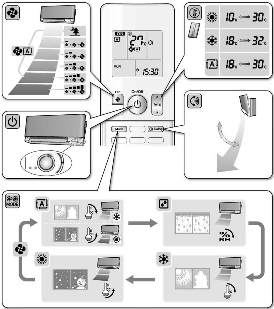
flowchart
graph TD
    A["App Store Air"] --> B["Fan On/Off"]
    B --> C["Mode Swing"]
    C --> D["Switch"]
    D --> E["Reversible Mode"]
    E --> F["Reversible Temperature"]
    F --> G["Reversible Humidity Indicator"]
    G --> H["Reversible Air Condition"]
    style A fill:#f9f,stroke:#333
    style B fill:#ccf,stroke:#333
    style C fill:#cfc,stroke:#333
    style D fill:#fcc,stroke:#333
    style E fill:#ffc,stroke:#333
    style F fill:#fcc,stroke:#333
    style G fill:#ffc,stroke:#333
    style H fill:#fcc,stroke:#333
FTXS20/25K2V1B, CTXS15/35K2V1B
Quick Reference
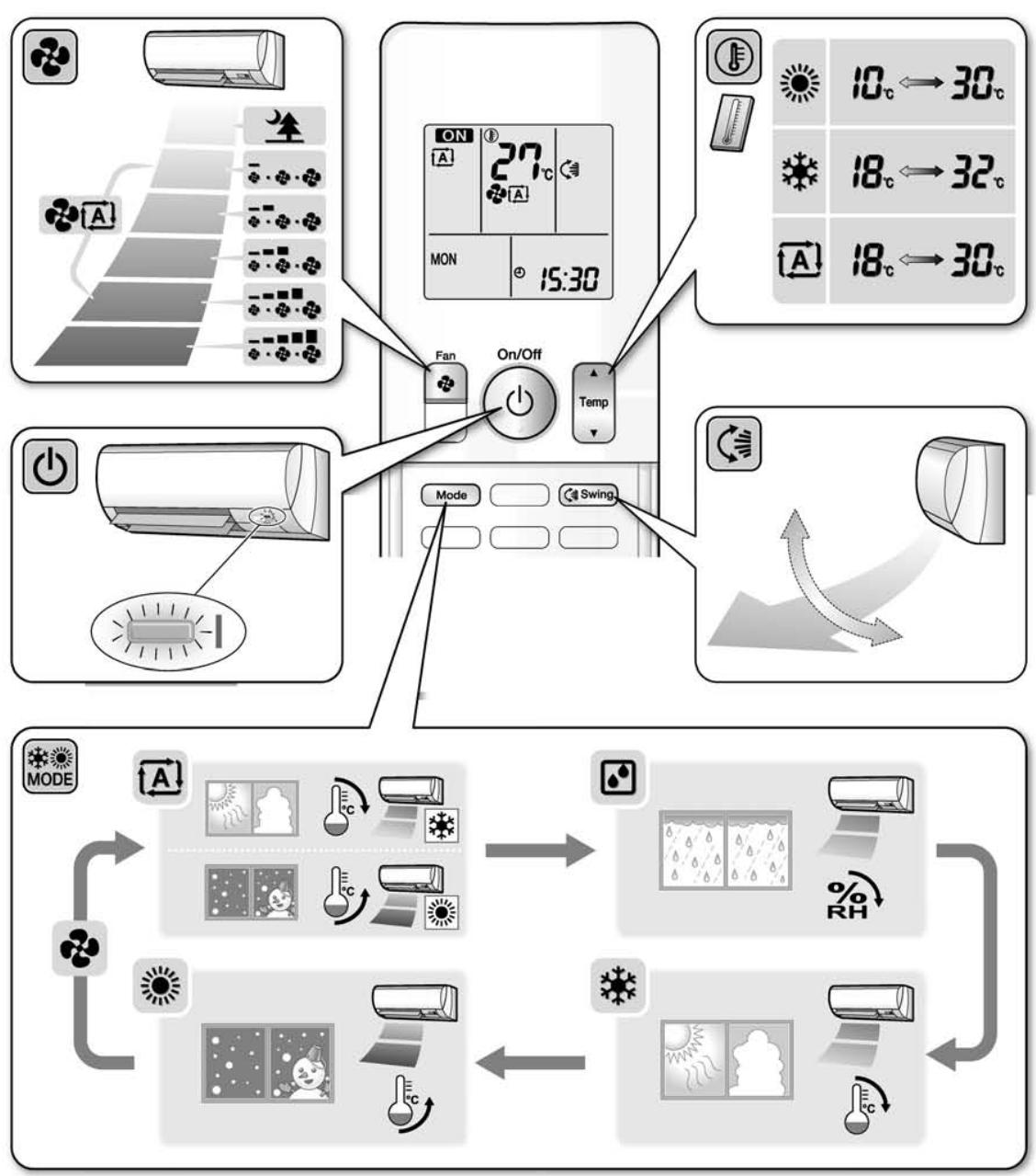
flowchart
graph TD
    A["Air Condition"] --> B["On/Off Fan"]
    B --> C["Mode"]
    B --> D["Swing"]
    E["Temperature Control"] --> F["ON 27°C MON 15:30"]
    G["Weather/Cooling"] --> H["10°C ← 30°C"]
    G --> I["18°C ← 32°C"]
    G --> J["18°C ← 30°C"]
    K["Directional Mode"] --> L["Receiving Air"]
    L --> M["Receiving Air"]
    M --> N["Receiving Air"]
    N --> O["Receiving Air"]
    O --> P["Receiving Air"]
    P --> Q["Receiving Air"]
    Q --> R["Receiving Air"]
    R --> S["Receiving Air"]
    S --> T["Receiving Air"]
    T --> U["Receiving Air"]
FVXG25/35/50K2V1B
Quick Reference
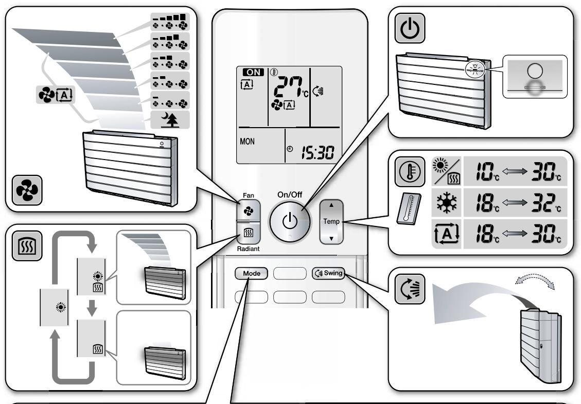
text_image
Diagram illustrating the installation of an air conditioner system with fan, radiant, and temperature control panels.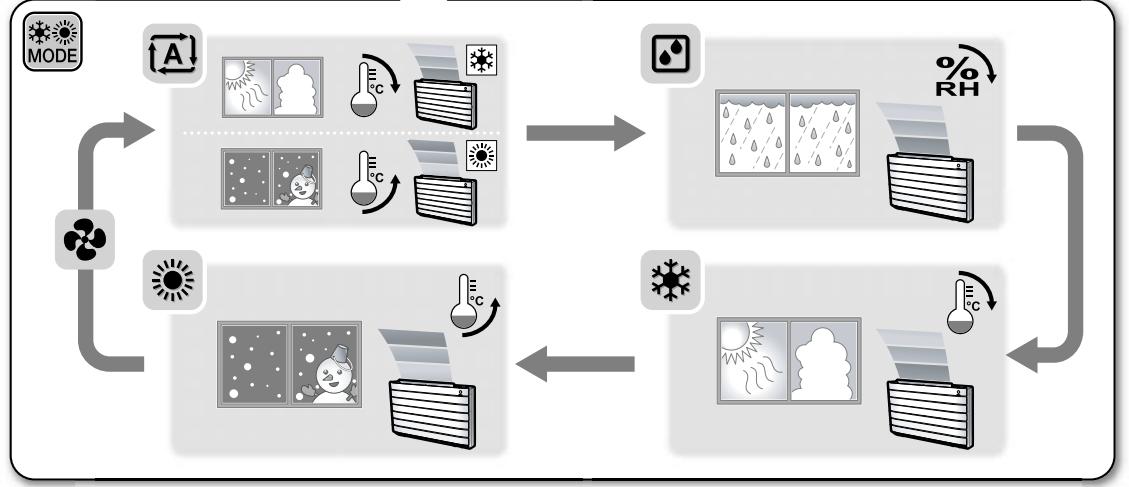
flowchart
graph TD
    A["MODE"] --> B["A"]
    B --> C["Weather Icon: Rain, Snow, Cloud"]
    C --> D["Temperature Sensor: 15°C, 20°C, 30°C"]
    D --> E["Light Storage System: 15% RH, 20% RH"]
    E --> F["Environment Indicator: Rain/Water, Temperature Sensor, Air Condition"]
    F --> G["Balance Sheet with Storm, Wind Turbines, Heat Exchanger"]
    G --> H["Recirculation Loop"]
    H --> I["Recovery Path"]
    I --> J["End"]
2.2 FTXS-J, FTXS-G, FVXS Series - ARC452A1, A3
2.2.1 Manual Contents and Reference Page
| Model Series | Wall Mounted Type | Floor Standing Type | |
| FTXS25-50J2V1B | FTXS60/71GV1B | FVXS25-50FV1B | |
| Read Before Operation | |||
| Names of Parts | 179 | 182 | 185 |
| Operation | |||
| AUTO · DRY · COOL · HEAT · FAN Operation ★ | 188 | 188 | 188 |
| Adjusting the Airflow Direction | 190 | 192 | 194 |
| COMFORT AIRFLOW and INTELLIGENT EYE Operation | 196 | 200 | — |
| POWERFUL Operation ★ | 203 | 203 | 203 |
| OUTDOOR UNIT QUIET Operation ★ | 204 | 204 | 204 |
| ECONO Operation ★ | 205 | 205 | 205 |
| OFF TIMER Operation ★ | 206 | 206 | 206 |
| ON TIMER Operation ★ | 207 | 207 | 207 |
| WEEKLY TIMER Operation ★ | 208 | 208 | 208 |
| Note for Multi System ★ | 216 | 216 | 216 |
| Drawing No. | 3P266959-2A | 3P248442-3 | 3P191290-1K |
★: The illustrations are for FTXS-J series as representative.
2.2.2 Names of Parts
FTXS20/25/35/42/50J2V1B
Names of Parts
■ Indoor Unit
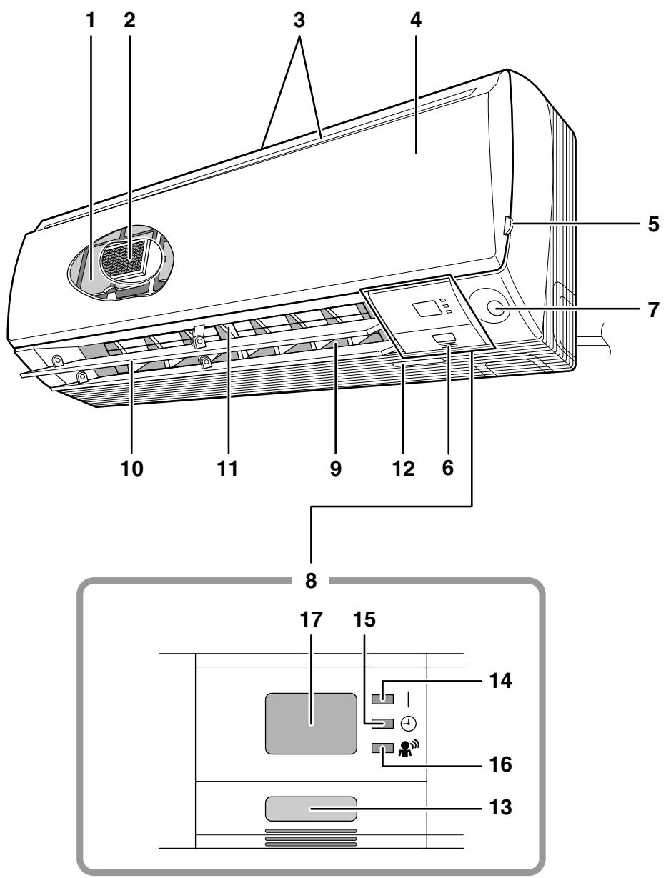
text_image
1 2 3 4 5 7 10 11 9 12 6 8 17 15 14 16 13■ Indoor Unit
1. Air filter
2. Titanium apatite photocatalytic air-purifying filter:
• These filters are attached to the inside of the air filters.
3. Air inlet
4. Front panel
5. Panel tab
6. Room temperature sensor:
- It senses the air temperature around the unit.
7. INTELLIGENT EYE sensor
8. Display
9. Air outlet
10. Flaps (horizontal blades)
11. Louvers (vertical blades):
- The louvers are inside of the air outlet.
12. Model name plate
13. Indoor unit ON/OFF switch:
- Push this switch once to start operation. Push once again to stop it.
- The operation mode refers to the following table.
| Model | Mode | Temperature setting | Airflow rate |
| COOLING ONLY | COOL | 22°C | AUTO |
| HEAT PUMP | AUTO | 25°C | AUTO |
- This switch is useful when the remote controller is missing.
14. OPERATION lamp (green)
15. TIMER lamp (yellow)
16. INTELLIGENT EYE lamp (green)
17. Signal receiver:
- It receives signals from the remote controller.
- When the unit receives a signal, you will hear a beep sound.
• Operation start ...... beep-beep
- Settings changed...... beep
• Operation stop ...... long beep
■ Remote Controller
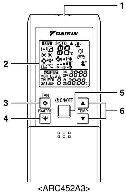
text_image
DAIKIN ON 8 STD 80°C A A WEEKY ON 38:88 MONTUEWED OFF THUFRI 8 ⊕ 38:88°C SATSUN 8 FAN POWERFUL ON/OFF TEMP- Signal transmitter:
- It sends signals to the indoor unit.
- Display:
- It displays the current settings. (In this illustration, each section is shown with its displays ON for the purpose of explanation.)
- FAN setting button:
- It selects the airflow rate setting.
- POWERFUL button:
POWERFUL operation
- ON/OFF button:
- Press this button once to start operation. Press once again to stop it.
- TEMPERATURE adjustment buttons:
- It changes the temperature setting.
- MODE selector button:
- It selects the operation mode. (AUTO/DRY/COOL/HEAT/FAN)
- QUIET button:
OUTDOOR UNIT QUIET operation
- ECONO button:
ECONO operation
- SWING button:
• Horizontal blades (flaps)
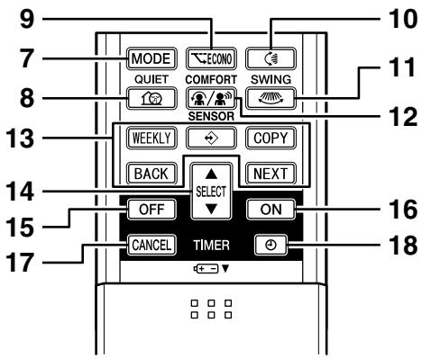
text_image
MODE ECO QUIET COMFORT SWING SENSOR WEEKLY COPY BACK NEXT SELECT ON OFF CANCEL TIMER 10 11 12 14 15 16 17- SWING button:
• Vertical blades (louvers)
- COMFORT/SENSOR button:
• COMFORT AIRFLOW and INTELLIGENT EYE operation
- WEEKLY/PROGRAM/COPY/BACK/NEXT button:
• WEEKLY TIMER operation
- SELECT button:
- It changes the ON/OFF TIMER and WEEKLY TIMER settings.
-
OFF TIMER button
-
ON TIMER button
-
TIMER CANCEL button:
- It cancels the timer setting. - It cannot be used for the WEEKLY TIMER operation.
- CLOCK button
FTXS60/71GV1B
Names of Parts
■ Indoor Unit
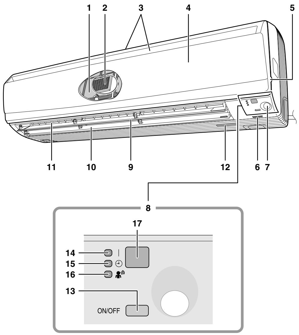
text_image
1 2 3 4 5 11 10 9 12 6 7 8 17 14 15 16 13 ON/OFF■ Indoor Unit
- Air filter
- Titanium apatite photocatalytic air-purifying filter:
• These filters are attached to the inside of the air filters.
-
Room temperature sensor:
-
Air inlet
- Front panel
- Panel tab
- It senses the air temperature around the unit.
- INTELLIGENT EYE sensor
- Display
-
Air outlet
-
Flaps (horizontal blades)
-
Louvers (vertical blades):
- The louvers are inside of the air outlet.
-
Model name plate
-
Indoor unit ON/OFF switch:
-
Push this switch once to start operation. Push once again to stop it.
- The operation mode refers to the following table.
| Model | Mode | Temperature setting | Airflow rate |
| COOLING ONLY | COOL | 22°C | AUTO |
| HEAT PUMP | AUTO | 25°C | AUTO |
- This switch is useful when the remote controller is missing.
- OPERATION lamp (green)
- TIMER lamp (yellow)
- INTELLIGENT EYE lamp (green)
-
Signal receiver:
-
It receives signals from the remote controller.
- When the unit receives a signal, you will hear a beep sound.
• Operation start ......beep-beep
- Settings changed......beep
• Operation stop......long beep
Names of Parts
■ Remote Controller

text_image
DAIKIN ON 1 STD 88°C ON MONTUWED ON 38:88 THUFRI ON 38:88°C SATSUN 8 FAN POWERFUL ON/OFF TEMP- Signal transmitter:
- It sends signals to the indoor unit.
- Display (LCD):
- It displays the current settings. (In this illustration, each section is shown with its displays on for the purpose of explanation.)
- FAN setting button:
- It selects the airflow rate setting.
- POWERFUL button:
POWERFUL operation
- ON/OFF button:
- Press this button once to start operation. Press once again to stop it.
- TEMPERATURE adjustment buttons:
- It changes the temperature setting.
- MODE selector button:
- It selects the operation mode. (AUTO/DRY/COOL/HEAT/FAN)
- QUIET button:
OUTDOOR UNIT QUIET operation
- ECONO button:
ECONO operation

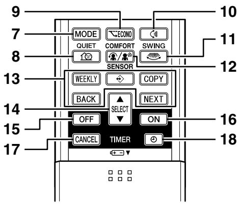
text_image
MODE ECONO QUIET COMFORT SWING SENSOR WEEKLY COPY BACK NEXT SELECT OFF ON CANCEL TIMER 9 7 8 10 11 12 14 15 16 17 18- SWING button:
- Flaps (horizontal blades)
- SWING button:
- Louvers (vertical blades)
- COMFORT/SENSOR button:
• COMFORT AIRFLOW and INTELLIGENT EYE operation
- WEEKLY/PROGRAM/COPY/BACK/NEXT button:
• WEEKLY TIMER operation
- SELECT button:
- It changes the ON/OFF TIMER and WEEKLY TIMER settings.
-
OFF TIMER button
-
ON TIMER button
-
TIMER CANCEL button:
- It cancels the timer setting. - It cannot be used for the WEEKLY TIMER operation.
- CLOCK button
FVXS25/35/50FV1B
Names of parts
■ Indoor Unit
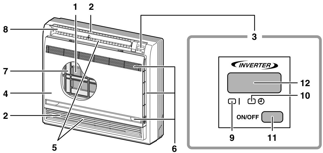
text_image
1 2 3 4 5 6 7 8 INVERTER 12 10 ON/OFF 9 11■ Opening the Front Panel
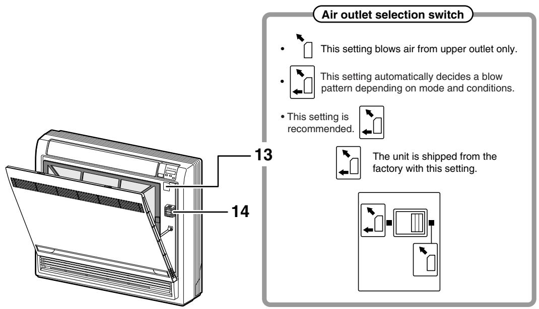
text_image
Air outlet selection switch • This setting blows air from upper outlet only. • This setting automatically decides a blow pattern depending on mode and conditions. • This setting is recommended. The unit is shipped from the factory with this setting. 13 14CAUTION
Before opening the front panel, be sure to stop the operation and turn the breaker OFF. Do not touch the metal parts on the inside of the indoor unit, as it may result in injury.
■ Indoor Unit
1. Titanium Apatite Photocatalytic Air-Purifying Filter:
- These filters are attached to the inside of the air filters.
-
Air outlet
-
Display
-
Front panel
-
Vertical blades (louvers)
- The louvers are inside of the air outlet.
-
Air inlet
-
Air filter
-
Horizontal blade (flap)
-
Operation lamp (green)
-
TIMER lamp (yellow)
-
Indoor Unit ON/OFF switch:
- Push this switch once to start operation. Push once again to stop it.
- The operation mode refers to the following table.
| Model | Mode | Temperature setting | Airflow rate |
| COOLING ONLY | COOL | 22°C | AUTO |
| HEAT PUMP | AUTO | 25°C | AUTO |
- This switch is useful when the remote controller is missing.
- Signal receiver:
- It receives signals from the remote controller.
- When the unit receives a signal, you will hear a short beep.
• Operation start ...... beep-beep
- Settings changed ..... beep
• Operation stop...... beeeeeep
-
Air outlet selection switch
-
Room temperature sensor:
- It senses the air temperature around the unit.
■ Remote Controller
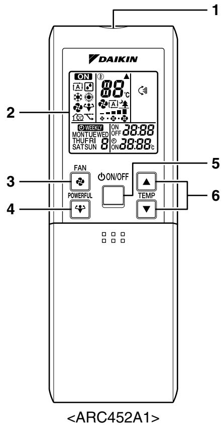
text_image
DAIKIN ON 88°C A A1 WEEKY ON 38:88 MONTUEVED OFF THUFRI ON 38:88 SATSUN ON 38:88°C FAN ON/OFF POWERFUL TEMP- Signal transmitter:
- It sends signals to the indoor unit.
- Display:
- It displays the current settings. (In this illustration, each section is shown with all its displays ON for the purpose of explanation.)
- FAN setting button:
- It selects the airflow rate setting.
- POWERFUL button:
POWERFUL operation
- ON/OFF button:
- Press this button once to start operation. Press once again to stop it.
- TEMPERATURE adjustment buttons:
- It changes the temperature setting.
- MODE selector button:
- It selects the operation mode. (AUTO/DRY/COOL/HEAT/FAN)
- QUIET button:
OUTDOOR UNIT QUIET operation

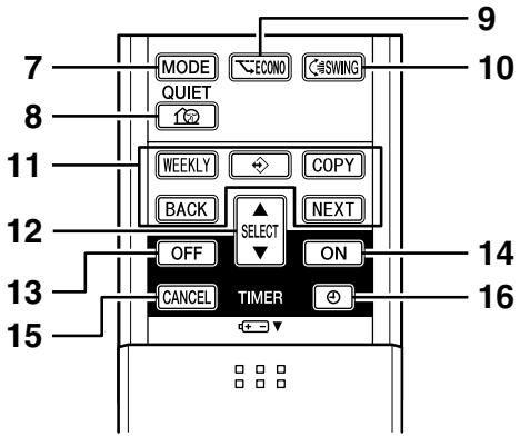
text_image
MODE ECONO GSWING QUIET WEEKLY COPY BACK SELECT NEXT OFF ON CANCEL TIMER 9 10 11 12 13 14 15 16- ECONO button:
ECONO operation
- SWING button:
- Adjusting the Airflow Direction
- WEEKLY/PROGRAM/COPY/BACK/NEXT button:
WEEKLY TIMER operation
- SELECT button:
- It changes the ON/OFF TIMER and WEEKLY TIMER settings.
-
OFF TIMER button
-
ON TIMER button
-
TIMER CANCEL button:
- It cancels the timer setting.
- It cannot be used for the WEEKLY TIMER operation.
- CLOCK button
2.2.3 AUTO · DRY · COOL · HEAT · FAN Operation
The air conditioner operates with the operation mode of your choice.
From the next time on, the air conditioner will operate with the same operation mode.
■ To start operation
1. Press MODE and select a operation mode.
• Each pressing of the button advances the mode setting in sequence.
A: AUTO
HEAT
: DRY
: FAN
: COOL
COOLING ONLY model
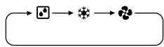
HEAT PUMP model
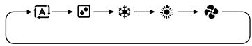
ON/OFF
2. Press ☐.
- “ON” is displayed on the LCD.
• The OPERATION lamp lights up.
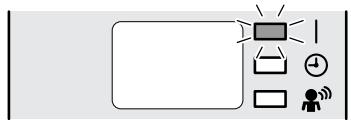
flowchart
graph TD
    A["User"] --> B["Timer Icon"]
    B --> C["User Icon"]
    C --> D["Timer Icon"]
    D --> E["User Icon"]
    E --> F["Timer Icon"]
    F --> G["User Icon"]
    G --> H["Timer Icon"]
    H --> I["User Icon"]
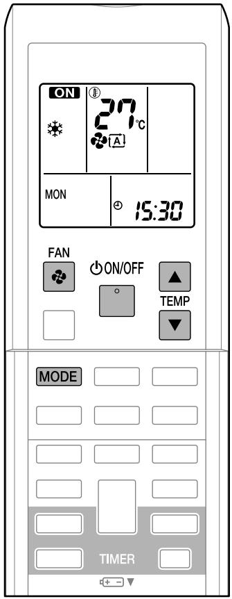
text_image
ON 27°C MON 15:30 FAN ON/OFF ▲ TEMP MODE TIMER■ To stop operation
ON/OFF
3. Press ☐ again.
- “ON” disappears from the LCD.
- Then OPERATION lamp goes off.
■ To change the temperature setting
4. Press ▲ or ▼.
| AUTO or COOL or HEAT operation | DRY or FAN operation |
| Press ▲ raise the temperature and press ▼ lower the temperature. | The temperature setting is not variable. |
| Set to the temperature you like. | ① \ 27 \ c | |

■ To change the airflow rate setting
5. Press

| AUTO or COOL or HEAT or FAN operation | DRY operation |
5 levels of airflow rate setting from “→” to “■” plus “A”  “▲” are available. “▲” are available. | The airflow rate setting is not variable. |
- Indoor unit quiet operation
When the airflow is set to “♠”, the noise from the indoor unit will become quieter. Use this when making the noise quieter.
NOTE
■ Notes on HEAT operation
- Since this air conditioner heats the room by taking heat from outdoor air to indoors, the heating capacity becomes smaller in lower outdoor temperatures. If the heating effect is insufficient, it is recommended to use another heating appliance in combination with the air conditioner.
- The heat pump system heats the room by circulating hot air around all parts of the room. After the start of heating operation, it takes some time before the room gets warmer.
- In heating operation, frost may occur on the outdoor unit and lower the heating capacity. In that case, the system switches into defrosting operation to take away the frost.
- During defrosting operation, hot air does not flow out of indoor unit.
- A pinging sound may be heard during defrosting operation, which, however does not mean that the air conditioner has failures.
■ Note on COOL operation
- This air conditioner cools the room by releasing the heat in the room outside.
Therefore, the cooling performance of the air conditioner may be degraded if the outdoor temperature is high.
■ Note on DRY operation
- The computer chip works to rid the room of humidity while maintaining the temperature as much as possible. It automatically controls temperature and airflow rate, so manual adjustment of these functions is unavailable.
■ Notes on AUTO operation
- In AUTO operation, the system selects an appropriate operation mode (COOL or HEAT) based on the room and outside temperatures and starts the operation.
- The system automatically reselects setting at a regular interval to bring the room temperature to user-setting level.
■ Note on FAN operation
- This mode is valid for fan only.
■ Note on airflow rate setting
- At smaller airflow rates, the cooling (heating) effect is also smaller.
2.2.4 Adjusting the Airflow Direction
FTXS20/25/35/42/50J2V1B
Adjusting the Airflow Direction
You can adjust the airflow direction to increase your comfort.
■ To start auto swing
Upper and lower airflow direction
Press

- “=” is displayed on the LCD.
- The flaps (horizontal blades) will begin to swing.
Right and left airflow direction
Press

- “” is displayed on the LCD.
- The louvers (vertical blades) will begin to swing.
The 3-D airflow direction
Press

and

[Non-Text]
- “◀” and “◀◀” are displayed on the LCD.
- The flaps and louvers move in turn.
- To cancel 3-D airflow, press either 🏠 or 🏠 again.
The flaps or louvers will stop moving.

text_image
ON 27°C A MON 15:30 SWING TIMER- The following illustrations show respective airflow directions.
Upper/Lower
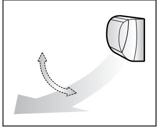
natural_image
Diagram showing a curved arrow and a 3D geometric shape with dashed lines, no text or symbols present.Right/Left
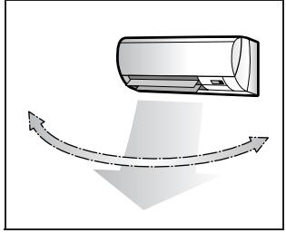
natural_image
Diagram showing airflow or fluid flow around a cylindrical object (no text or symbols)3-D
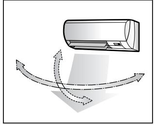
natural_image
Diagram showing airflow around a car with curved arrows indicating direction (no text or symbols)■ To set the flaps or louvers at desired position
- This function is effective while flaps or louvers are in auto swing mode.
Press 🏠 and 🏠 when the flaps or louvers have reached the desired position.
- In the 3-D airflow, the flaps and louvers move in turn.
- “◀” or “◀◀◀” disappears from the LCD.

CAUTION
- Always use a remote controller to adjust the angles of the flaps and louvers. If you attempt to move the flaps and louvers forcibly with hand when they are swinging, the mechanism may be broken.
- Always use a remote controller to adjust the louvers angles. In side the air outlet, a fan is rotating at a high speed.
NOTE
■ Note on the angles of the flaps
- The flaps swinging range depends on the operation. (See the figure.)
■ Note on 3-D airflow
- Using 3-D airflow circulates cold air, which tends to collected at the bottom of the room, and hot air, which tends to collect near the ceiling, throughout the room, preventing are as of cold and hot developing.
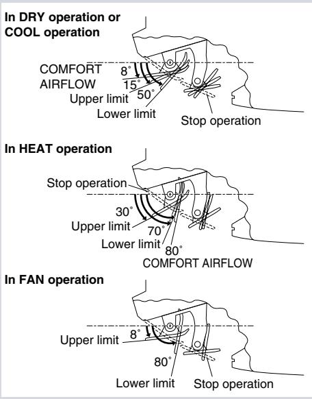
FTXS60/71GV1B
Adjusting the Airflow Direction
You can adjust the airflow direction to increase your comfort.
■ To start auto swing
Upper and lower airflow direction
Press
- “=” is displayed on the LCD.
- The flaps (horizontal blades) will begin to swing.
Right and left airflow direction
Press

- “” is displayed on the LCD.
- The louvers (vertical blades) will begin to swing.
The 3-D airflow direction
Press

and

- “◀” and “◀◀◀” are displayed on the LCD.
- The flaps and louvers move in turn.
- To cancel 3-D airflow, press either 🏠 or 🏠 again.
The flaps or louvers will stop moving.
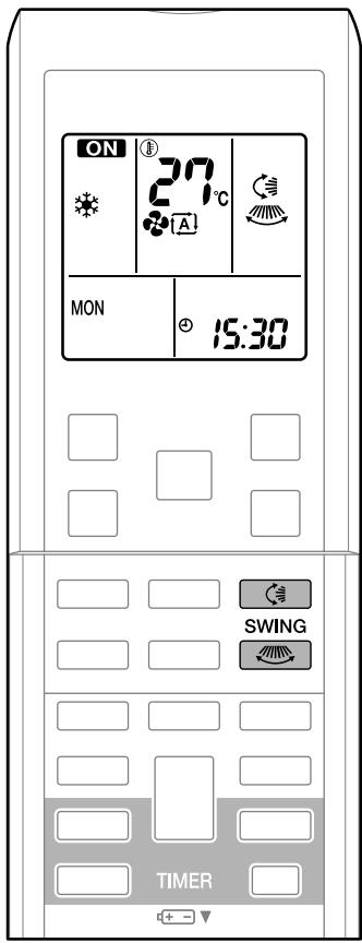
text_image
ON 27°C A MON 15:30 SWING TIMER- The following illustrations show respective airflow directions.
Upper/Lower
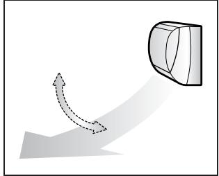
natural_image
Diagram showing a curved arrow and a 3D geometric shape with dashed lines, no text or symbols present.Right/Left

natural_image
Diagram showing a cylindrical object with a curved arrow indicating motion or force, no text or symbols present3-D
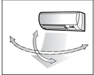
natural_image
Diagram of a car air conditioner with airflow arrows indicating airflow direction (no text or symbols)■ To set the flaps or louvers at desired position
- This function is effective while flaps or louvers are in auto swing mode.
Press 🏠 and 🏠 when the flaps or louvers have reached the desired position.
- In the 3-D airflow, the flaps and louvers move in turn.
- “◀” or “◀◀◀” disappears from the LCD.

CAUTION
- Always use a remote controller to adjust the angles of the flaps and louvers. If you attempt to move it forcibly with hand when it is swinging, the mechanism may be broken.
- Always use a remote controller to adjust the louvers angles. In side the air outlet, a fan is rotating at a high speed.
NOTE
■ Note on the angles of the flaps
- The flaps swinging range depends on the operation. (See the figure.)
■ Note on 3-D airflow
- Using 3-D airflow circulates cold air, which tends to collected at the bottom of the room, and hot air, which tends to collect near the ceiling, throughout the room, preventing areas of cold and hot developing.
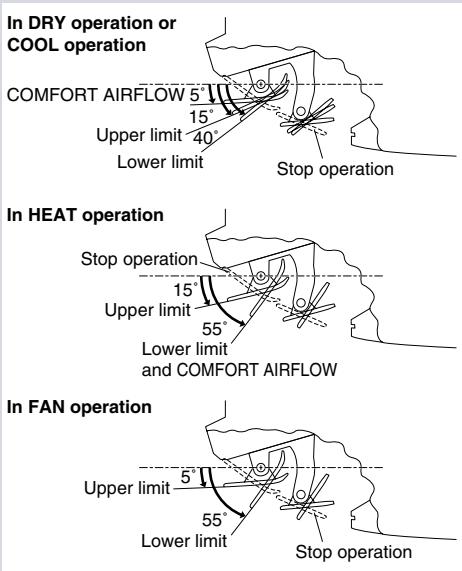
FVXS25/35/50FV1B
Adjusting the Airflow Direction
You can adjust the airflow direction to increase your comfort.
■ To adjust the horizontal blade (flap)
1. Press "SWING button

- “⇐” is displayed on the LCD and the flaps will begin to swing.
2. When the flap has reached the desired position, press "SWING button" once more.
- The flap will stop moving.
- “◀” disappears from the LCD.
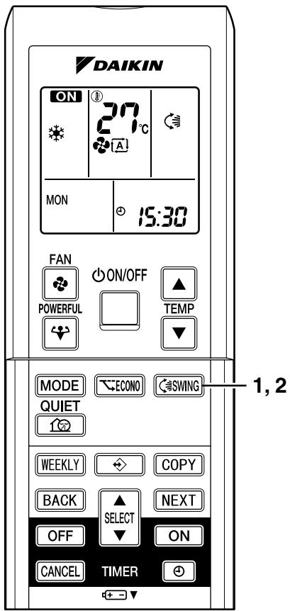
text_image
DAIKIN ON 27°C MON 15:30 FAN ON/OFF POWERFUL TEMP MODE ECONO SWING QUIET WEEKLY COPY BACK SELECT NEXT OFF ON CANCEL TIMER + -▼ 1, 2■ To adjust the vertical blades (louvers)
Hold the knob and move the louver.
(You will find a knob on the left-side and the right-side blades.)
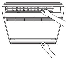
natural_image
Line drawing of a hand pressing down on a device panel (no text or symbols)Notes on flap and louvers angle
- Unless “SWING” is selected, you should set the flap at a near-horizontal angle in HEAT mode and at a upward position in COOL or DRY mode to obtain the best performance.
■ ATTENTION
- When adjusting the flap by hand, turn off the unit, and use the remote controller to restart the unit.
- Be careful when adjusting the louvers. Inside the air outlet, a fan is rotating at a high speed.
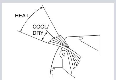
text_image
HEAT COOL/ DRY■ Airflow selection
- Make airflow selection according to what suits you.
When setting the airflow selection switch to

- Air conditioner automatically decides the appropriate blowing pattern depending on the operating mode/situation.
| Operating mode | Situation | Blowing pattern |
| COOL mode | When the room has become fully cool, or when one hour has passed since turning on the air conditioner. | So that air does not come into direct contact with people, air is blown upper air outlet, room temperature is equalized. |
| At start of operation or other times when the room is not fully cooled. | 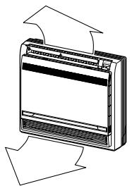 | |
| HEAT mode | At times other than below. (Normal time.) | Air is blown from the upper and lower air outlets for high speed cooling during COOL mode, and for filling the room with warm air during HEAT mode. |
| At start or when air temperature is low. | So that air does not come into direct contact with people. Air is blown upper air outlet. |
- During Dry mode, so that cold air does not come into direct contact with people, air is blown upper air outlet.
When setting the air outlet selection switch to 📁.
- Regardless of the operating mode or situation, air blows from the upper air outlet.
- Use this switch when you do not want air coming out of the lower air outlet. (While sleeping etc.)
CAUTION
- Do not try to adjust the flap by hand.
- When adjusting by hand, the mechanism may not operate properly or condensation may drip from air outlets.
2.2.5 COMFORT AIRFLOW and INTELLIGENT EYE Operation
FTXS20/25/35/42/50J2V1B
COMFORT AIRFLOW and INTELLIGENT EYE Operation
■ COMFORT AIRFLOW operation
The flow of air will be in the upward direction while in COOL operation and in the downward direction while in HEAT operation, which will provide a comfortable wind that will not come in direct contact with people.
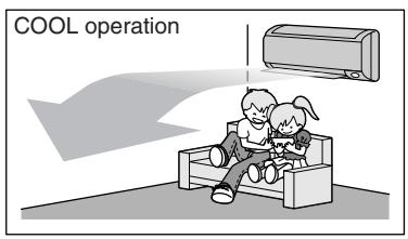
text_image
COOL operation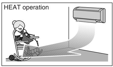
text_image
HEAT operation■ INTELLIGENT EYE operation
"INTELLIGENT EYE" is the infrared sensor which detects the human movement. If no one is in the room for more than 20 minutes, the operation automatically changes to energy saving operation. The INTELLIGENT EYE sensor according to the following situations.
■ A person is detected in area 1.
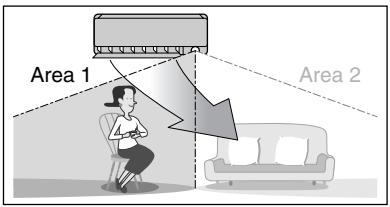
text_image
Area 1 Area 2■ A person is detected in area 2.
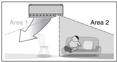
text_image
Area 1 Area 2■ People are detected in both areas.
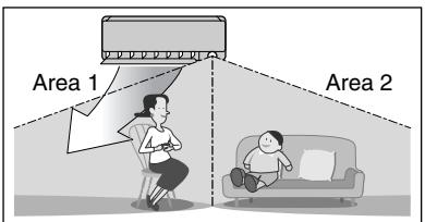
text_image
Area 1 Area 2Use the INTELLIGENT EYE Operation in combination with the COMFORT AIRFLOW Operation.
■ No people are detected in the areas.
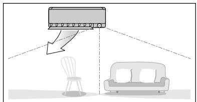
natural_image
Diagram showing a car air conditioner emitting exhaust from a chair to a sofa, with no text or symbols present.The air conditioner will go into energy-saving mode after 20 minutes.
*The wind direction may differ from the illustrated direction depending on the actions and movements of the people in the areas.
■ To start operation
Press 🏠/ 🏠 and select the desired mode.
- Each time the 📤/ passengers is pressed a different setting option is displayed on the LCD.
- By selecting “💡💡” from the following icons, the air conditioner will be in COMFORT AIRFLOW operation combined with INTELLIGENT EYE operation.
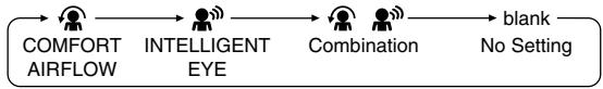
flowchart
graph LR
    A["COMFORT AIRFLOW"] --> B["INTELLIGENT EYE"]
    B --> C["Combination"]
    C --> D["blank\nNo Setting"]
- When the flaps (horizontal blades) are swinging, the operating as above will stop movement of them.
- The INTELLIGENT EYE lamp lights up.
- The lamp will be lit while human movements are detected.
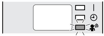
flowchart
graph TD
    A[" "] --> B[" "]
    B --> C[" "]
    C --> D[" "]
    D --> E[" "]
    E --> F[" "]
    style A fill:#fff,stroke:#000
    style B fill:#fff,stroke:#000
    style C fill:#fff,stroke:#000
    style D fill:#fff,stroke:#000
    style E fill:#fff,stroke:#000
    style F fill:#fff,stroke:#000
■ To cancel operation
Press 🏠/ 🏠 and select "blank" on the LCD.
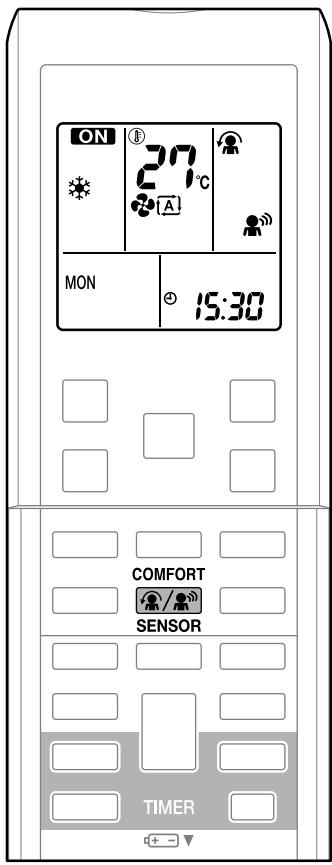
text_image
ON 27°C A MON 15:30 COMFORT SENSOR TIMER| Display | Operation mode | Explanation |
| COMFORT AIRFLOW | The flaps will adjust the airflow direction upward while cooling, and adjust the airflow direction downward while heating. | |
| INTELLIGENT EYE | The sensors will detect the movement of people in the sensing areas and the louvers will adjust the airflow direction to an area where people are not present. When there are no people in the sensing areas, the air conditioner will go into energy-saving mode. | |
| COMFORT AIRFLOW and INTELLIGENT EYE | The air conditioner will be in COMFORT AIRFLOW operation combined with INTELLIGENT EYE operation. | |
| Blank | No function | - |
COMFORT AIRFLOW and INTELLIGENT EYE Operation
NOTE
■ Notes on COMFORT AIRFLOW operation
- The flap position will change, preventing air from blowing directly on the occupants of the room.
- POWERFUL operation and COMFORT AIRFLOW operation cannot be used at the same time.
- Priority is given to the function of whichever button is pressed last.
- The airflow rate will be set to AUTO. If the upper and lower airflow direction is selected, the COMFORT AIRFLOW operation will be canceled.
■ Notes on INTELLIGENT EYE operation
- Application range is as follows.
Vertical angle 90° (Side view)

text_image
7m 90°Horizontal angle 110° (Top view)
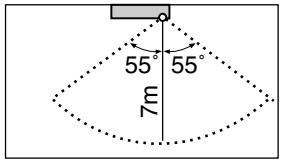
text_image
55° 55° 7m- While the air conditioner is in INTELLIGENT EYE operation, the louvers will adjust the airflow direction if there are people in the sensing areas of the INTELLIGENT EYE so that the leftward or rightward airflow will not be directed to the people.
If no people are detected in either area 1 or 2 in 20 minutes, the air conditioner will go into energy-saving mode with the set temperature shifted by 2^ C.
The air conditioner may go into energy-saving operation even if there are people in the areas. This may occur depending on the clothes the people are wearing if there are no movements of the people in the areas.
- The airflow direction from the louvers will be leftward if there are people in both areas 1 and 2 or if there is a person right in front of the sensors because the sensors on the both sides will detect the person.
- Due to the position of the sensor, people might be exposed to the airflow of the indoor unit if they are close to the front side of the indoor unit.
If there are people close to the front side of the indoor unit or in both areas, it is recommended to use the COMFORT AIRFLOW and INTELLIGENT EYE functions simultaneously. When both of them are in use, the air conditioner will not direct the airflow towards the people.
- Sensor may not detect moving objects further than 7m away. (Check the application range)
- Sensor detection sensitivity changes according to indoor unit location, the speed of passersby, temperature range, etc.
- The sensor also mistakenly detects pets, sunlight, fluttering curtains and light reflected off of mirrors as passersby.
- INTELLIGENT EYE operation will not go on during POWERFUL operation.
- NIGHT SET mode will not go on during use of INTELLIGENT EYE operation.
NOTE
■ Note on combination of COMFORT AIRFLOW operation and INTELLIGENT EYE operation
- The airflow rate will be set to AUTO. If the upper and lower airflow direction is selected, the COMFORT AIRFLOW operation will be canceled. Priority is given to the function of whichever button is pressed last.
- The air conditioner can go into operation with the COMFORT AIRFLOW and INTELLIGENT EYE functions combined.
The flaps adjust the airflow direction upward (while in cooling operation) and downward (while in heating operation), during which the sensors of the INTELLIGENT EYE are working to detect the movement of people. When the sensors detect people, the louvers will direct the airflow in such way that it will not be blown directly on them. If there are no people, the air conditioner will go into energy-saving operation after 20 minutes.
INTELLIGENT EYE operation is useful for energy saving
■ Energy saving operation
- If no presence detected in the room for 20 minutes, the energy saving operation will start.
- This operation changes the temperature -2^ in HEAT / +2^ in COOL / +2^ in DRY operation from set temperature.
- This operation decreases the airflow rate slightly in FAN operation only.
CAUTION
- Do not place large objects near the sensor.
Also keep heating units or humidifiers outside the sensor's detection area. This sensor can detect undesirable objects. - Do not hit or violently push the INTELLIGENT EYE sensor. This can lead to damage and malfunction.
FTXS60/71GV1B
COMFORT AIRFLOW and INTELLIGENT EYE Operation
■ COMFORT AIRFLOW operation
The flow of air will be in the upward direction while in COOL operation and in the downward direction while in HEAT operation, which will provide a comfortable wind that will not come in direct contact with people.
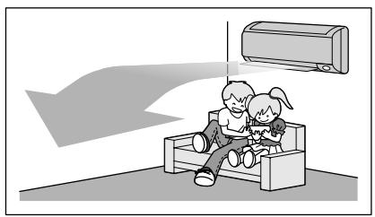
natural_image
Illustration of two children sitting on a bench with an air conditioner above, no text or symbols presentCOOL operation

natural_image
Illustration of a person using a cart to interact with a large air conditioner unit (no text or symbols present)HEAT operation
■ INTELLIGENT EYE operation
"INTELLIGENT EYE" is the infrared sensor which detects the human movement.
If nobody in the room for more than 20 minutes, the operation automatically changes to energy saving operation.
[Example]
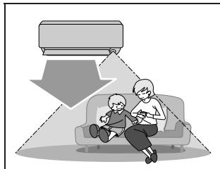
natural_image
Illustration of a child sitting on a sofa using a tablet, with an umbrella and camera screen above (no text or symbols)When somebody in the room

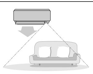
natural_image
Diagram showing a sofa with a mounted air conditioner unit above it, connected to a floor-mounted device (no text or symbols present)When nobody in the room

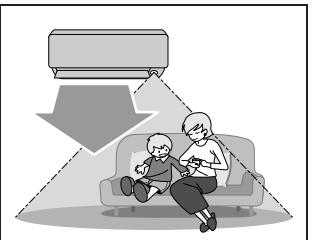
natural_image
Illustration of an elderly person sitting on a sofa watching a car, with a downward arrow indicating motion (no text or symbols)Somebody back in the room
■ Normal operation
- The air conditioner is in normal operation while the sensor is detecting the movement of people.
- The INTELLIGENT EYE lamp lights up.
■ 20 minutes after, start energy saving operation.
- The set temperature is shifted in ± 2^ steps.
- The INTELLIGENT EYE lamp is goes off.
■ Back to normal operation.
- The air conditioner will return to normal operation when the sensor detects the movement of people again.
- The INTELLIGENT EYE lamp lights up again.
■ To combine COMFORT AIRFLOW and INTELLIGENT EYE operation
The air conditioner can go into operation with the COMFORT AIRFLOW and INTELLIGENT EYE operation combined.
■ To start operation
Press 🐘/ passengers and select the desired mode.
- Each time the 📷/ passengers is pressed a different setting option is displayed on the LCD.
- By selecting “💡💡” from the following icons, the air conditioner will be in COMFORT AIRFLOW operation combined with INTELLIGENT EYE operation.

flowchart
graph LR
    A["COMFORT AIRFLOW"] --> B["INTELLIGENT EYE"]
    B --> C["Combination"]
    C --> D["blank"]
    D --> E["No Setting"]
- When the flaps (horizontal blades) are swinging, the operating as above will stop movement of them.
- The INTELLIGENT EYE lamp lights up.
- The lamp will be lit while human movements are detected.
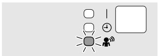
■ To cancel operation
Press 🏠/ passengers and select "blank" on the LCD.
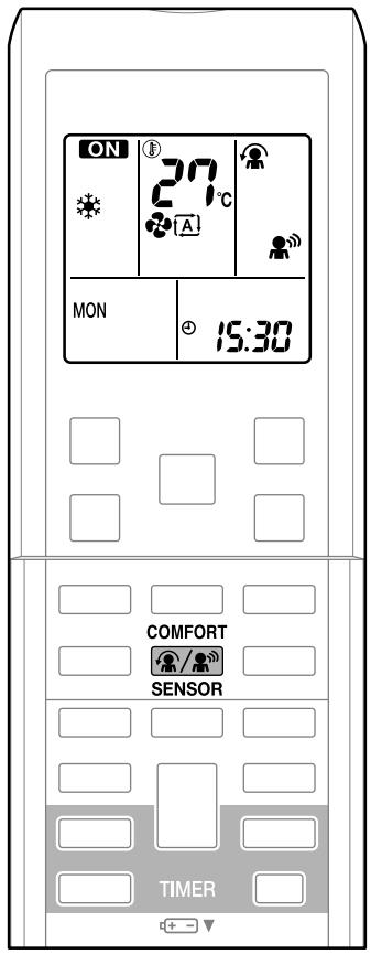
text_image
ON 27°C A MON 15:30 COMFORT SENSOR TIMERINTELLIGENT EYE operation is useful for energy saving
■ Energy saving operation
- If no presence detected in the room for 20 minutes, the energy saving operation will start.
- This operation changes the temperature -2^ in HEAT / +2^ in COOL / +2^ in DRY operation from set temperature.
- This operation decreases the airflow rate slightly in FAN operation only.
COMFORT AIRFLOW and INTELLIGENT EYE Operation
NOTE
■ Notes on COMFORT AIRFLOW operation
- The flap position will change, preventing air from blowing directly on the occupants of the room.
- POWERFUL operation and COMFORT AIRFLOW operation cannot be used at the same time.
Priority is given to the function of whichever button is pressed last. - The airflow rate will be set to AUTO. If the upper and lower airflow direction is selected, the COMFORT AIRFLOW operation will be canceled.
■ Notes on INTELLIGENT EYE operation
- Application range is as follows.
Vertical angle 90° (Side view)
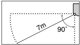
text_image
7m 90°Horizontal angle 110° (Top view)
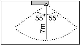
text_image
55° 55° 7m- Sensor may not detect moving objects further than 7m away. (Check the application range)
- Sensor detection sensitivity changes according to indoor unit location, the speed of passersby, temperature range, etc.
- The sensor also mistakenly detects pets, sunlight, fluttering curtains and light reflected off of mirrors as passersby.
- INTELLIGENT EYE operation will not go on during POWERFUL operation.
- NIGHT SET mode will not go on during use of INTELLIGENT EYE operation.
■ Note on combination of COMFORT AIRFLOW operation and INTELLIGENT EYE operation
- The airflow rate will be set to AUTO. If the upper and lower airflow direction is selected, the COMFORT AIRFLOW operation will be canceled.
Priority is given to the function of whichever button is pressed last.
CAUTION
- Do not place large objects near the sensor.
Also keep heating units or humidifiers outside the sensor's detection area. This sensor can detect undesirable objects. - Do not hit or violently push the INTELLIGENT EYE sensor. This can lead to damage and malfunction.
2.2.6 POWERFUL Operation
POWERFUL Operation
POWERFUL operation quickly maximizes the cooling (heating) effect in any operation mode. You can get the maximum capacity.
■ To start POWERFUL operation
1. Press

- POWERFUL operation ends in 20 minutes. Then the system automatically operates again with the previous settings which were used before POWERFUL operation.
- “” is displayed on the LCD.
■ To cancel POWERFUL operation
2. Press

again.
- “” disappears from the LCD.
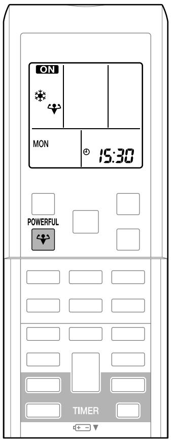
text_image
ON MON 15:30 POWERFUL TIMERNOTE
■ Notes on POWERFUL operation
- When using POWERFUL operation, there are some functions which are not available.
- POWERFUL operation cannot be used together with ECONO, COMFORT AIRFLOW or OUTDOOR UNIT QUIET operation. Priority is given to the function of whichever button is pressed last.
- POWERFUL operation can only be set when the unit is running.
- POWERFUL operation will not increase the capacity of the air conditioner if the air conditioner is already in operation with its maximum capacity demonstrated.
• In COOL, HEAT and AUTO mode
To maximize the cooling (heating) effect, the capacity of outdoor unit is increased and the airflow rate is fixed to the maximum setting.
The temperature and airflow settings are not variable.
• In DRY operation
The temperature setting is lowered by 2.5^ C and the airflow rate is slightly increased.
- In FAN operation
The airflow rate is fixed to the maximum setting.
2.2.7 OUTDOOR UNIT QUIET Operation
OUTDOOR UNIT QUIET Operation
OUTDOOR UNIT QUIET operation lowers the noise level of the outdoor unit by changing the frequency and fan speed on the outdoor unit. This function is convenient during night.
■ To start OUTDOOR UNIT QUIET operation
1. Press

- “山区” is displayed on the LCD.
■ To cancel OUTDOOR UNIT QUIET operation
2. Press

again.
- “” disappears from the LCD.
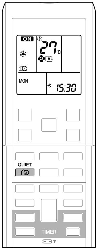
text_image
ON 27°C MON 15:30 QUIET TIMERNOTE
■ Notes on OUTDOOR UNIT QUIET operation
- If using a multi system, the OUTDOOR UNIT QUIET operation will work only when this function is set on all operated indoor units.
- This function is available in COOL, HEAT, and AUTO operation. (This is not available in FAN and DRY operation.)
- POWERFUL operation and OUTDOOR UNIT QUIET operation cannot be used at the same time. Priority is given to the function of whichever button is pressed last.
- Even the operation is stopped using the remote controller or the indoor unit ON/OFF switch when using OUTDOOR UNIT QUIET operation, “💡” will remain on the remote controller display.
- OUTDOOR UNIT QUIET operation will drop neither the frequency nor fan speed if the frequency and fan speed have been already dropped low enough.
2.2.8 ECONO Operation
ECONO Operation
ECONO operation is a function which enables efficient operation by limiting the maximum power consumption value.
This function is useful for cases in which attention should be paid to ensure a circuit breaker will not trip when the product runs alongside other appliances.
■ To start ECONO operation
1. Press ECONO .
- “ ” is displayed on the LCD.
■ To cancel ECONO operation
2. Press ECONO again.
- “ ” disappears from the LCD.
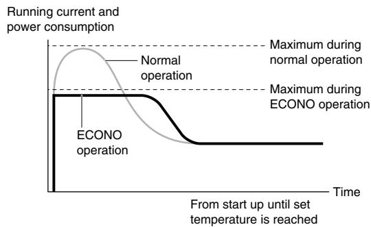
line
| Time | ECONO operation | Normal operation | |------|-----------------|------------------| | 0 | 0 | 0 | | Peak | 0 | Peak | | End | 0 | 0 |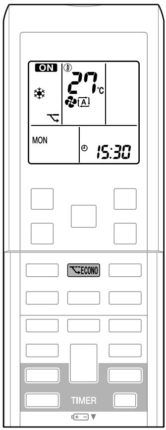
text_image
ON 27°C MON 15:30 ECONO TIMER- This diagram is a representation for illustrative purposes only.
* The maximum running current and power consumption of the air conditioner in ECONO operation vary with the connecting outdoor unit.
NOTE
■ Notes on ECONO operation
- ECONO operation can only be set when the unit is running.
- ECONO operation is a function which enables efficient operation by limiting the power consumption of the outdoor unit (operating frequency).
- ECONO operation functions in AUTO, COOL, DRY and HEAT operation.
- POWERFUL and ECONO operation cannot be used at the same time. Priority is given to the function of whichever button is pressed last.
- If the level of power consumption is already low, ECONO operation will not drop the power consumption.
2.2.9 OFF TIMER Operation
OFF TIMER Operation
Timer functions are useful for automatically switching the air conditioner on or off at night or in the morning. You can also use OFF TIMER and ON TIMER in combination.
■ To use OFF TIMER operation
- Check that the clock is correct. If not, set the clock to the present time.
1. Press OFF .
- “OFF” and setting time are displayed on the LCD.
- “0:00” is displayed on the LCD.
- “OFF” blinks.
2. Press SELECT until the time setting reaches the point you like.
• Each pressing of either button increases or decreases the time setting by 10 minutes. Holding down either button changes the setting rapidly.
3. Press OFF again.
• The TIMER lamp lights up.
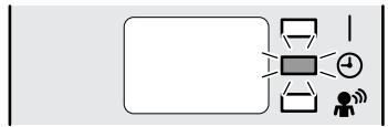
flowchart
graph TD
    A["User"] --> B["Device"]
    B --> C["Control Unit"]
    C --> D["Feedback Loop"]
    D --> E["User icon"]
    style A fill:#f9f,stroke:#333
    style B fill:#ccf,stroke:#333
    style C fill:#cfc,stroke:#333
    style D fill:#fcc,stroke:#333
    style E fill:#ffc,stroke:#333
■ To cancel the OFF TIMER Operation
4. Press CANCEL .
- “OFF” and setting time disappear from the LCD.
- “💡” and day of the week are displayed on the LCD.
- The TIMER lamp goes off.
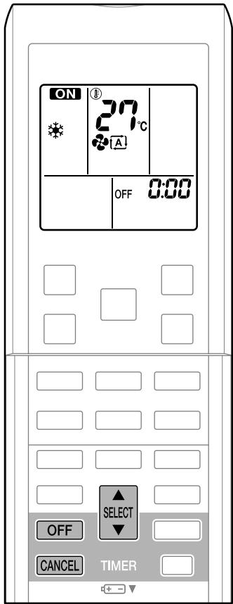
text_image
ON 27°C OFF 0.00 SELECT OFF CANCEL TIMERNOTE
■ Notes on TIMER operation
- When TIMER is set, the present time is not displayed.
- Once you set ON/OFF TIMER, the time setting is kept in the memory. The memory is canceled when remote controller batteries are replaced.
- When operating the unit via the ON/OFF TIMER, the actual length of operation may vary from the time entered by the user. (Maximum approx. 10 minutes)
■ NIGHT SET mode
When the OFF TIMER is set, the air conditioner automatically adjusts the temperature setting (0.5°C up in COOL, 2.0°C down in HEAT) to prevent excessive cooling (heating) for your pleasant sleep.
2.2.10 ON TIMER Operation
ON TIMER Operation
■ To use ON TIMER operation
- Check that the clock is correct. If not, set the clock to the present time.
1. Press ON .
- “ON” and setting time are displayed on the LCD.
- “5:00” is displayed on the LCD.
- “ON” blinks.
2. Press SELECT until the time setting reaches the point you like.
• Each pressing of either button increases or decreases the time setting by 10 minutes. Holding down either button changes the setting rapidly.
3. Press ON again.
• The TIMER lamp lights up.
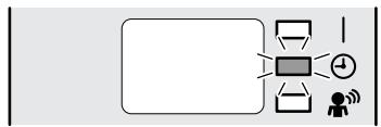
flowchart
graph LR
    A["Input"] --> B["Processing"]
    B --> C["Output"]
    style A fill:#fff,stroke:#000
    style B fill:#ccc,stroke:#000
    style C fill:#fff,stroke:#000
■ To cancel ON TIMER operation
4. Press CANCEL .
- “ON” and setting time disappear from the LCD.
- “💡” and day of the week are displayed on the LCD.
• The TIMER lamp goes off.
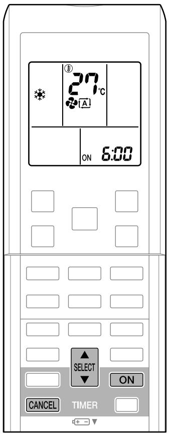
text_image
27°C ON 6:00 SELECT ON CANCEL TIMER■ To combine ON TIMER and OFF TIMER
- A sample setting for combining the 2 timers is shown below.
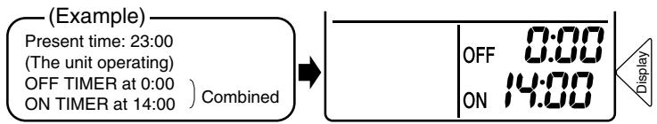
text_image
(Example) Present time: 23:00 (The unit operating) OFF TIMER at 0:00 ) ON TIMER at 14:00 ) Combined OFF 0:00 ON 14:00 DisplayNOTE
■ In the following cases, set the timer again.
• After a breaker has turned off.
• After a power failure.
• After replacing batteries in the remote controller.
2.2.11 WEEKLY TIMER Operation
WEEKLY TIMER Operation
Up to 4 timer settings can be saved for each day of the week. It is convenient if the WEEKLY TIMER is set according to the family's life style.
■ Using in these cases of WEEKLY TIMER
An example of WEEKLY TIMER settings is shown below.
Example: The same timer settings are made for the week from Monday through Friday while different timer settings are made for the weekend.
| [Monday] | Make timer settings up to programs 1-4. | |||
| Program 1 ON 25°C OFF 6:00 8:30 17:30 22:00 Program 2 ON OFF OFF Program 3 ON OFF Program 4 OFF Program 1 ON 25°C OFF Program 2 ON 27°C OFF Program 3 ON 27°C OFF Program 4 OFF Program 1 ON 25°C OFF Program 2 ON 27°C OFF Program 3 ON 27°C OFF Program 4 OFF Program 1 ON 25°C OFF Program 2 ON 27°C OFF Program 3 ON 27°C OFF Program 4 OFF Program 1 ON 30000000000000000000000000000000000000000000000000000000000000000000000000000000000000000000000000000 | ||||
| [Tuesday] to [Friday] | Use the copy mode to make settings for Tuesday to Friday, because these settings are the same as those for Monday. | |||
| Program 1 ON 25°C OFF 6:00 8:30 17:30 22:00 | ||||
| [Saturday] | No timer settings | |||
| [Sunday] | Make timer settings up to programs 1-4. | |||
| Program 1 ON 25°C OFF 8:00 10:00 19:00 21:00 | ||||
| Program 2 ON 27°C OFF OFF | ||||
| Program 3 ON 27°C OFF | ||||
| Program 4 ON 27°C | ||||
- Up to 4 reservations per day and 28 reservations per week can be set in the WEEKLY TIMER. The effective use of the copy mode ensures ease of making reservations.
- The use of ON-ON-ON-ON settings, for example, makes it possible to schedule operating mode and set temperature changes. Furthermore, by using OFF-OFF-OFF-OFF settings, only the turn-off time of each day can be set. This will turn off the air conditioner automatically if the user forgets to turn it off.
WEEKLY TIMER Operation
■ To use WEEKLY TIMER operation
Setting mode
- Make sure the day of the week and time are set. If not, set the day of the week and time.
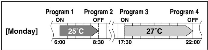
line
| Program | Timeframe Label | Temperature (°C) | |---|---|---| | Program 1 | 6:00 | ON | | Program 2 | 8:30 | OFF | | Program 3 | 17:30 | ON | | Program 4 | 22:00 | OFF | [Monday] 25°C1. Press
- The day of the week and the reservation number of the current day will be displayed.
- 1 to 4 settings can be made per day.
2. Press SELECT to select the desired day of the week and reservation number.
- Pressing the ▲ SELECT changes the reservation number and the day of the week.
3. Press NEXT .
- The day of the week and reservation number will be set.
- “WEEKLY” and “ON” blink.
4. Press ▲ SELECT to select the desired mode.
- Pressing the ▲▲▼ changes “ON” or “OFF” setting in sequence.
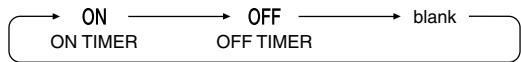
- In case the reservation has already been set, selecting “blank” deletes the reservation.
- Go to step 9 if "blank" is selected.
5. Press NEXT .
- The ON/OFF TIMER mode will be set.
- “ WEEKLY ” and the time blink.
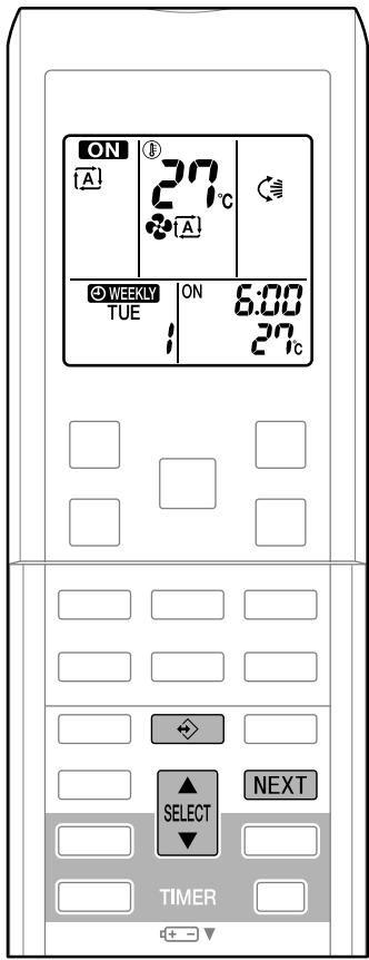
text_image
ON A 27°C A WEEKLY TUE ON 6:00 27°C NEXT SELECT TIMER6. Press SELECT to select the desired time.
- The time can be set between 0:00 and 23:50 in 10 minute intervals.
- To return to the ON/OFF TIMER mode setting, press
BACK - Go to step 9 when setting the OFF TIMER.
7. Press NEXT .
- The time will be set.
- “ WEEKLY ” and the temperature blink.
8. Press | SELECT to select the desired
temperature.
- The temperature can be set between 10^ and 32^ .
Cooling: The unit operates at 18^ C even if it is set at 10 to 17^ C.
Heating: The unit operates at 30^ C even if it is set at 31 to 32^ C. - To return to the time setting, press BACK.
- The set temperature is only displayed when the mode setting is on.
9. Press NEXT .
- The temperature will be set and go to the next reservation setting.
- To continue further settings, repeat the procedure from step 4.

text_image
ON A 27°C A WEEKLY TUE ON 6:00 1 27°C BACK SELECT NEXT TIMER10. Press ◆ to complete the setting.
- Be sure to direct the remote controller toward the indoor unit and check for a receiving tone and flashing the OPERATION lamp.
- “WEEKLY” is displayed on the LCD and WEEKLY TIMER operation is activated.
• The TIMER lamp lights up. - A reservation made once can be easily copied and the same settings used for another day of the week.
Refer to copy mode.
WEEKLY TIMER Operation
Setting Displays
Day and number


ON/OFF


Time

Temperature
NOTE
■ Notes on WEEKLY TIMER operation
- Do not forget to set the clock on the remote control first.
- The day of the week, ON/OFF TIMER mode, time and set temperature (only for ON TIMER mode) can be set with WEEKLY TIMER. Other settings for ON TIMER are based on the settings just before the operation.
- Both WEEKLY TIMER and ON/OFF TIMER operation cannot be used at the same time. The ON/OFF TIMER operation has priority if it is set while WEEKLY TIMER is still active. The WEEKLY TIMER will go into standby state, and “WEEKLY” will disappear from the LCD. When ON/OFF TIMER is up, the WEEKLY TIMER will automatically become active.
- Only the time and set temperature with the weekly timer are sent with the ⬆. Set the weekly timer only after setting the operation mode, the fan strength, and the fan direction ahead of time.
- Shutting the breaker off, power failure, and other similar events will render operation of the indoor unit's internal clock inaccurate. Reset the clock.
- The BACK can be used only for the time and temperature settings. It cannot be used to go back to the reservation number.
Copy mode
- A reservation made once can be copied another day of the week. The whole reservation of the selected day of the week will be copied.
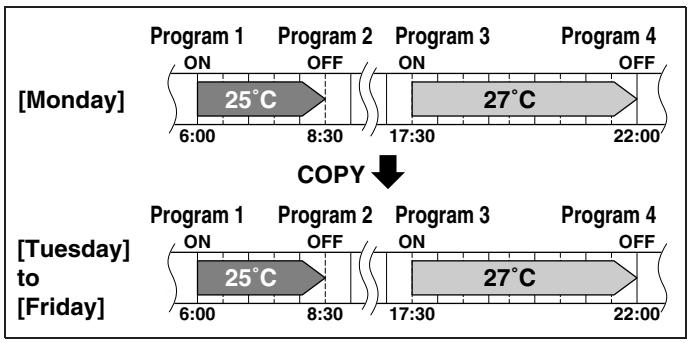
text_image
[Monday] Program 1 ON Program 2 OFF 6:00 8:30 Program 3 ON 27°C 17:30 22:00 Program 4 OFF COPY [Tuesday] to [Friday] Program 1 ON Program 2 OFF 6:00 8:30 Program 3 ON 27°C 17:30 22:00 Program 4 OFF- Press
- Press SELECT to confirm the day of the week to be copied.
- Press COPY to activate copy mode.
- The whole reservation of the selected day of the week will be copied.
- Press SELECT to select the destination day of the week.
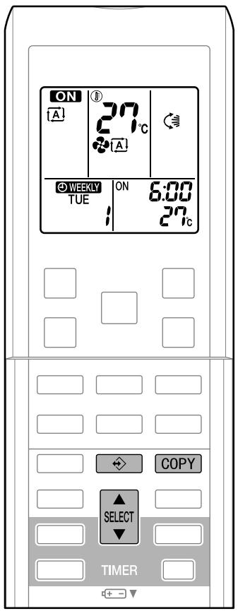
text_image
ON A 27°C A WEEKLY TUE ON 6:00 1 27°C COPY SELECT TIMERWEEKLY TIMER Operation
5. Press COPY .
- The reservation will be copied to the selected day of the week. The whole reservation of the selected day of the week will be copied.
- To continue copying the settings to other days of the week, repeat step 4 and step 5.
6. Press → to complete the setting.
- “WEEKLY” is displayed on the LCD and WEEKLY TIMER operation is activated.
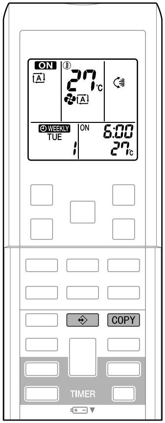
text_image
ON A 27°C A WEEKLY TUE ON 6:00 1 27°C COPY TIMERSetting Displays
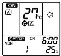
text_image
ON A 27°C A © WEEKLY MON ON 6:00 25°CConfirmation
▶
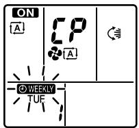
text_image
ON A CP A © WEEKLY TUFCopy
▶
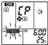
text_image
ON A CP A WEEKLY TUF ON 6:00 25cPaste
▶
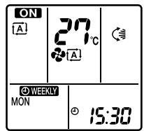
text_image
ON [A] 27°C © WEEKLY MON 15:30Normal
NOTE
■ Note on COPY MODE
- The entire reservation of the source day of the week is copied in the copy mode. In the case of making a reservation change for any day of the week individually after copying the content of weekly reservations, press and change the settings in the steps of setting mode.
■ Confirming a reservation
- The reservation can be confirmed.
1. Press
- The day of the week and the reservation number of current day will be displayed.
2. Press SELECT to select the day of the week and the reservation number to be confirmed.
- Pressing the ▲ SELECT ▼ displays the reservation details.
- To change the confirmed reserved settings, select the reservation number and press NEXT.
The mode is switched to setting mode. Go to setting mode step 4.
3. Press → to exit confirming mode.
- “WEEKLY” is displayed on the LCD and WEEKLY TIMER operation is activated.
• The TIMER lamp lights up.
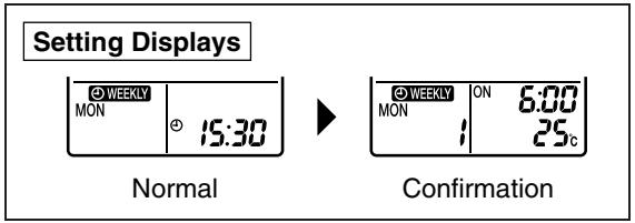
text_image
Setting Displays WEEKLY MON 15:30 Normal WEEKLY ON 6:00 MON 1 25c Confirmation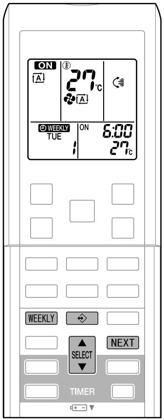
text_image
ON A 27°C A WEEKLY TUE ON 6:00 27°C WEEKLY SELECT NEXT TIMER■ To deactivate WEEKLY TIMER operation
4. Press WEEKLY while “WEEKLY” is displayed on the LCD.
- “ WEEKLY ” disappears from the LCD.
- The TIMER lamp goes off.
- To reactivate the WEEKLY TIMER operation, press the WEEKLY again.
- If a reservation deactivated with WEEKLY is activated once again, the last reservation mode will be used.
WEEKLY TIMER Operation
■ To delete reservations
The individual reservation
- Refer to setting mode. When selecting desired mode at step 4 in setting mode, select "blank". The reservation will be deleted.
The reservations for each day of the week
- This function can be used for deleting reservations for each day of the week. - It can be used while confirming or setting reservations.
5. Press
6. Select the day of the week to be canceled

7. Hold WEEKLY for 5 seconds.
- The reservation of the selected day of the week will be deleted.
All reservations
8. Hold WEEKLY for 5 seconds while normal display.
- Be sure to direct the remote control toward the main unit and check for a receiving tone.
- This operation is not effective on the setting display of WEEKLY TIMER.
- All reservations will be deleted.

text_image
ON A 27°C A WEEKLY TUE ON 6:00 27°C WEEKLY SELECT NEXT TIMER2.2.12 Note for Multi System
Note for Multi System
This system has one outdoor unit connected to multiple indoor units.
■ Selecting the operation mode
1. With the priority room setting present but inactive or not present.
When more than 1 indoor unit is operating, priority is given to the first unit that was turned on. In this case, set the units that are turned on later to the same operation mode as the first unit. Otherwise, they will enter the standby state, and the OPERATION lamp will flash: this does not indicate malfunction.
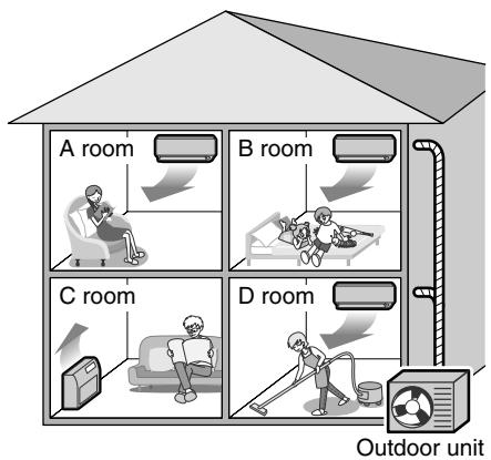
text_image
A room B room C room D room Outdoor unitNOTE
■ Notes on operation mode for multi system
- COOL, DRY and FAN operation may be used at the same time.
- AUTO operation automatically selects COOL operation or HEAT operation based on the room temperature.
Therefore, AUTO operation is available when selecting the same operation mode as that of the room with the first unit to be turned on.
CAUTION
- Normally, the operation mode in the room where the unit is first run is given priority, but the following situations are exceptions, so please keep this in mind.
If the operation mode of the first room is FAN operation, then using HEAT operation in any room after this will give priority to HEAT operation. In this situation, the air conditioner running in FAN operation will go on standby, and the OPERATION lamp will flash.
2. With the priority room setting active.
See “Priority room setting” on the next page.
■ NIGHT QUIET mode (Available only for COOL operation)
NIGHT QUIET mode requires initial programming during installation. Please consult your retailer or dealer for assistance.
NIGHT QUIET mode reduces the operation noise of the outdoor unit during the night time hours to prevent annoyance to neighbors.
- The NIGHT QUIET mode is activated when the temperature drops 5^ or more below the highest temperature recorded that day. Therefore, when the temperature difference is less than 5^ , this function will not be activated.
- NIGHT QUIET mode reduces slightly the cooling efficiency of the unit.
Note for Multi System
■ OUTDOOR UNIT QUIET operation
1. With the priority room setting present but inactive or not present.
When using the OUTDOOR UNIT QUIET operation feature with the Multi system, set all indoor units to OUTDOOR UNIT QUIET operation using their remote controllers.
When clearing OUTDOOR UNIT QUIET operation, clear one of the operating indoor units using their remote controller. However OUTDOOR UNIT QUIET operation display remains on the remote controller for other rooms. We recommend you release all rooms using their remote controllers.
2. With the priority room setting active.
See "Priority room setting".
■ COOL/HEAT mode lock
(Available only for heat pump models)
The COOL/HEAT mode lock requires initial programming during installation. Please consult your authorized dealer for assistance. The COOL/HEAT mode lock sets the unit forcibly to either COOL or HEAT operation. This function is convenient when you wish to set all indoor units connected to the multi system to the same operation mode.
NOTE
- The COOL/HEAT mode lock cannot be activated together with the priority room setting.
■ Priority room setting
The priority room setting requires initial programming during installation. Please consult your retailer or dealer for assistance. The room designated as the priority room takes priority in the following situations;
1. Operation mode priority.
As the operation mode of the priority room takes precedence, the user can select a different operation mode from other rooms.
* Room A is the priority room in the examples.
When COOL operation is selected in room A while operating the following modes in room B, C and D:
| Operation mode in room B, C and D | Status of room B, C and D when the unit in room A is in COOL operation |
| COOL or DRY or FAN | Current operation mode maintained |
| HEAT | The unit enters standby mode. Operation resumes when the room A unit stops operating. |
| AUTO | If the unit is set to COOL operation, it continues. If set to HEAT operation, it enters standby mode. Operation resumes when the room A unit stops operating. |
2. Priority when POWERFUL operation is used.
* Room A is the priority room in the examples.
The indoor units in rooms A, B, C and D are all operating. If the unit in room A enters POWERFUL operation, operation capacity will be concentrated in room A. In such a case, the cooling (heating) efficiency of the units in rooms B, C and D may be slightly reduced.
3. Priority when using OUTDOOR UNIT QUIET operation.
* Room A is the priority room in the examples.
Just by setting the unit in room A to QUIET operation, the air conditioner starts OUTDOOR UNIT QUIET operation. You don't have to set all the operated indoor units to QUIET operation.
2.3 FLXS, FDXS Series - ARC433B67, B69
2.3.1 Manual Contents and Reference Page
| Model Series | Floor / Ceiling Suspended Dual Type | Duct Connected Type |
| FLXS25-60BAVMB | FDXS25/35E7VMBFDXS50/60C7VMB | |
| Read Before Operation | ||
| Remote Controller | 219 | 220 |
| Operation | ||
| AUTO · DRY · COOL · HEAT · FAN Operation ★ | 221 | 221 |
| Adjusting the Airflow Direction | 223 | — |
| POWERFUL Operation ★ | 225 | 225 |
| OUTDOOR UNIT QUIET Operation ★ | 226 | 226 |
| HOME LEAVE Operation ★ | 227 | 227 |
| TIMER Operation ★ | 229 | 229 |
| Note for Multi System | 231 | 231 |
| Drawing No. | 3P194444-5C | 3P196326-9C (Reference) |
★: The illustrations are for FLXS series as representative.
2.3.2 Remote Controller
FLXS25/35/50/60BAVMB
■ Remote Controller
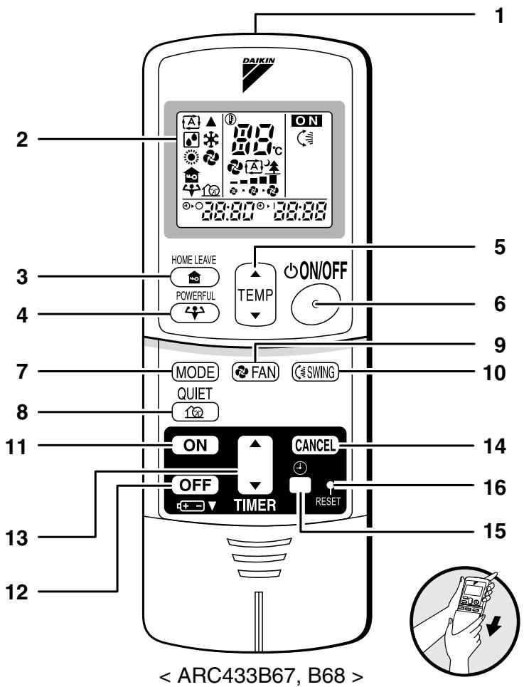
text_image
DAIKIN 2 3 4 5 6 7 8 9 10 11 12 < ARC433B67, B68 >- Signal transmitter:
- It sends signals to the indoor unit.
- Display:
- It displays the current settings. (In this illustration, each section is shown with all its displays ON for the purpose of explanation.)
- HOME LEAVE button:
HOME LEAVE operation
- POWERFUL button:
POWERFUL operation
- TEMPERATURE adjustment buttons:
- It changes the temperature setting.
- ON/OFF button:
- Press this button once to start operation. Press once again to stop it.
- MODE selector button:
- It selects the operation mode. (AUTO/DRY/COOL/HEAT/FAN)
-
QUIET button: OUTDOOR UNIT QUIET operation
-
FAN setting button:
- It selects the air flow rate setting.
-
SWING button
-
ON TIMER button
-
OFF TIMER button
-
TIMER Setting button:
- It changes the time setting.
- TIMER CANCEL button:
- It cancels the timer setting.
-
CLOCK button
-
RESET button:
-
Restart the unit if it freezes.
- Use a thin object to push.
FDXS25/35E7VMB, FDXS50/60C7VMB
■ Remote Controller
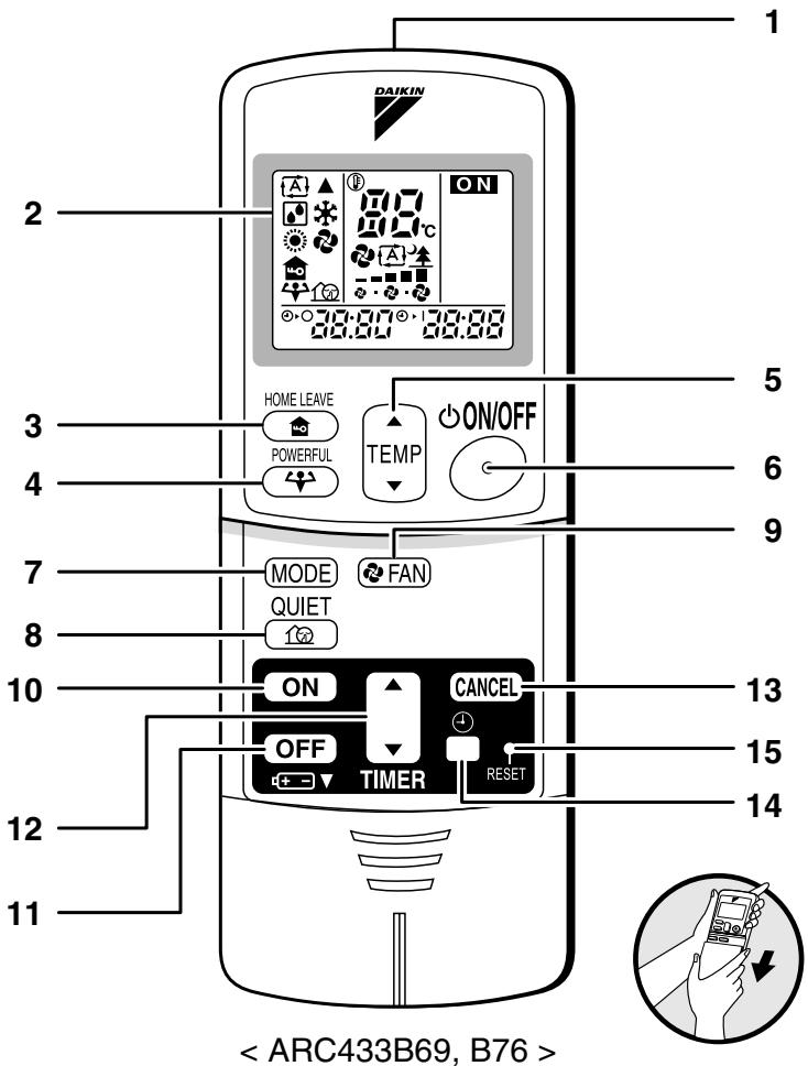
text_image
DAIKIN 1 2 ON 3 HOME LEAVE POWERFUL TEMP ON/OFF 5 6 4 7 MODE FAN QUIET 8 10 ON CANCEL OFF TIMER RESET 13 15 14 12 11 < ARC433B69, B76 >1. Signal transmitter:
- It sends signals to the indoor unit.
2. Display:
- It displays the current settings. (In this illustration, each section is shown with all its displays ON for the purpose of explanation.)
3. HOME LEAVE button:
HOME LEAVE operation
4. POWERFUL button:
POWERFUL operation
5. TEMPERATURE adjustment buttons:
- It changes the temperature setting.
6. ON/OFF button:
- Press this button once to start operation. Press once again to stop it.
7. MODE selector button:
- It selects the operation mode. (AUTO/DRY/COOL/HEAT/FAN)
8. QUIET button: OUTDOOR UNIT QUIET operation
9. FAN setting button:
- It selects the air flow rate setting.
10. ON TIMER button
11. OFF TIMER button
12. TIMER Setting button:
- It changes the time setting.
13. TIMER CANCEL button:
- It cancels the timer setting.
14. CLOCK button
15. RESET button:
- Restart the unit if it freezes. - Use a thin object to push.
The air conditioner operates with the operation mode of your choice.
From the next time on, the air conditioner will operate with the same operation mode.
■ To start operation
1. Press "MODE selector button" and select a operation mode.
• Each pressing of the button advances the mode setting in sequence.
A: AUTO
: DRY
: COOL
HEAT
: FAN

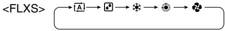
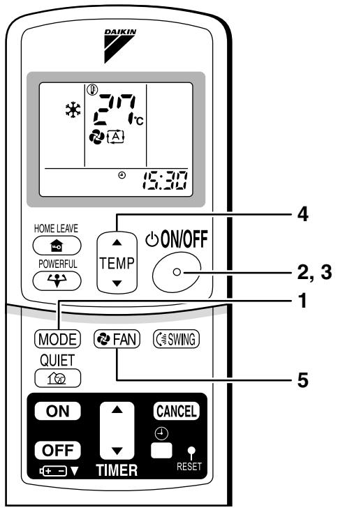
text_image
DAIKIN 27°C 15:30 HOME LEAVE POWERFUL TEMP ON/OFF MODE FAN SWING QUIET ON CANCEL OFF TIMER RESET 4 2, 3 1 52. Press "ON/OFF button".
- The OPERATION lamp lights up.

■ To stop operation
3. Press "ON/OFF button" again.
- Then OPERATION lamp goes off.
■ To change the temperature setting
- Press "TEMPERATURE adjustment button".
| DRY or FAN mode | AUTO or COOL or HEAT mode |
| The temperature setting is not variable. | Press “▲” to raise the temperature and press“▼” to lower the temperature. |
| Set to the temperature you like. 9 \ 2 \ 1 |
■ To change the air flow rate setting
5. Press "FAN setting button".
| DRY mode | AUTO or COOL or HEAT or FAN mode |
| The air flow rate setting is not variable. | Five levels of air flow rate setting from “ ♂ ” to “ ” plus “ ♂ ” “ ” are available. |
- Indoor unit quiet operation
When the air flow is set to “▲”, the noise from the indoor unit will become quieter.
Use this when making the noise quieter.
The unit might lose capacity when the air flow rate is set to a weak level.
NOTE
■ Note on HEAT operation
- Since this air conditioner heats the room by taking heat from outdoor air to indoors, the heating capacity becomes smaller in lower outdoor temperatures. If the heating effect is insufficient, it is recommended to use another heating appliance in combination with the air conditioner.
- The heat pump system heats the room by circulating hot air around all parts of the room. After the start of heating operation, it takes some time before the room gets warmer.
- In heating operation, frost may occur on the outdoor unit and lower the heating capacity. In that case, the system switches into defrosting operation to take away the frost.
- During defrosting operation, hot air does not flow out of indoor unit.
■ Note on COOL operation
- This air conditioner cools the room by blowing the hot air in the room outside, so if the outside temperature is high, performance drops.
■ Note on DRY operation
- The computer chip works to rid the room of humidity while maintaining the temperature as much as possible. It automatically controls temperature and fan strength, so manual adjustment of these functions is unavailable.
■ Note on AUTO operation
- In AUTO operation, the system selects a temperature setting and an appropriate operation mode (COOL or HEAT) based on the room temperature at the start of the operation.
- The system automatically reselects setting at a regular interval to bring the room temperature to user-setting level.
- If you do not like AUTO operation, you can manually select the operation mode and setting you like.
■ Note on air flow rate setting
- At smaller air flow rates, the cooling (heating) effect is also smaller.
2.3.4 Adjusting the Airflow Direction
FLXS25/35/50/60BAVMB
Adjusting the Airflow Direction
You can adjust the air flow direction to increase your comfort.
■ To adjust the horizontal blade (flap)
1. Press "SWING button".
- “ ⏻ ” is displayed on the LCD and the flaps will begin to swing.
2. When the flaps have reached the desired position, press "SWING button" once more.
• The flap will stop moving.
- “ ⬇ ” disappears from the LCD.
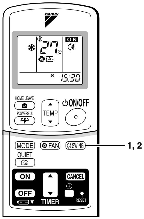
text_image
DAIKIN 717 21°C ON 15:30 HOME LEAVE POWERFUL TEMP ON/OFF MODE FAN SWING QUIET 10° ON CANCEL OFF TIMER RESET 1, 2■ To adjust the vertical blades (louvers)
- When adjusting the louver, use a robust and stable stool and watch your steps carefully.
Hold the knob and move the louvers.
(You will find a knob on the left side and the right side blades.)
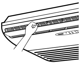
natural_image
Line drawing of a hand pressing down on a car grille (no text or symbols)Notes on flap and louvers angles.
- Unless [SWING] is selected, you should set the flap at a near- horizontal angle in COOL or DRY mode to obtain the best performance.
- In COOL or DRY mode, if the flap is fixed at a downward position, the flap automatically moves in about 60 minutes to prevent condensation on it.
■ ATTENTION
- Always use a remote controller to adjust the flap angle.
If you attempt to move it forcibly with hand when it is swinging, the mechanism may be broken.
- Be careful when adjusting the louvers. Inside the air outlet, a fan is rotating at a high speed.
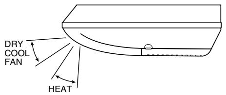
text_image
DRY COOL FAN HEAT2.3.5 POWERFUL Operation
POWERFUL Operation
POWERFUL operation quickly maximizes the cooling (heating) effect in any operation mode. You can get the maximum capacity.
■ To start POWERFUL operation
1. Press "POWERFUL button".
- POWERFUL operation ends in 20 minutes. Then the system automatically operates again with the settings which were used before POWERFUL operation.
- When using POWERFUL operation, there are some functions which are not available.
- “ ” is displayed on the LCD.
■ To cancel POWERFUL operation
2. Press "POWERFUL button" again.
- “” disappears from the LCD.
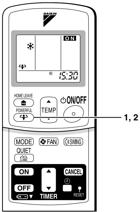
text_image
DAIKIN ON 15:30 HOME LEAVE POWERFUL TEMP ON/OFF MODE FAN SWING QUIET ON CANCEL OFF TIMER RESET 1, 2NOTE
■ Notes on POWERFUL operation
- In COOL and HEAT mode To maximize the cooling (heating) effect, the capacity of outdoor unit must be increased and the air flow rate be fixed to the maximum setting. The temperature and air flow settings are not variable.
- In DRY mode The temperature setting is lowered by 2.5°C and the air flow rate is slightly increased.
- In FAN mode The air flow rate is fixed to the maximum setting.
2.3.6 OUTDOOR UNIT QUIET Operation
OUTDOOR UNIT QUIET Operation
OUTDOOR UNIT QUIET operation lowers the noise level of the outdoor unit by changing the frequency and fan speed on the outdoor unit. This function is convenient during night.
■ To start OUTDOOR UNIT QUIET operation
1. Press "QUIET button".
- “💡” is displayed on the LCD.
■ To cancel OUTDOOR UNIT QUIET operation
2. Press "QUIET button" again.
- “山区” disappears from the LCD.
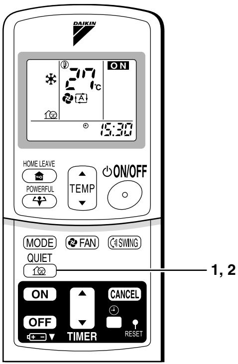
text_image
DAIKIN 717 21°C ON 15:30 HOME LEAVE POWERFUL TEMP ON/OFF MODE FAN SWING QUIET ON CANCEL OFF TIMER RESET 1, 2NOTE
■ Note on OUTDOOR UNIT QUIET operation
- This function is available in COOL, HEAT, and AUTO modes.
(This is not available in FAN and DRY mode.)
- POWERFUL operation and OUTDOOR UNIT QUIET operation cannot be used at the same time.
Priority is given to the function of whichever button is pressed last.
- If operation is stopped using the remote controller or the main unit ON/OFF switch when using OUTDOOR UNIT QUIET operation, “💡” will remain on the remote controller display.
2.3.7 HOME LEAVE Operation
HOME LEAVE Operation
HOME LEAVE operation is a function which allows you to record your preferred temperature and air flow rate settings.
■ To start HOME LEAVE operation
1. Press "HOME LEAVE button".
• The HOME LEAVE lamp lights up.

■ To cancel HOME LEAVE operation
2. Press "HOME LEAVE button" again.
• The HOME LEAVE lamp goes off.
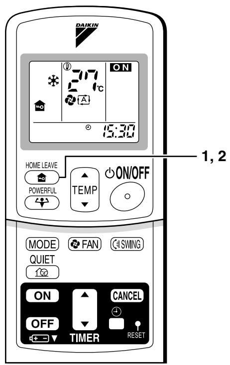
text_image
DAIKIN 37°C ON 15:30 HOME LEAVE POWERFUL TEMP ON/OFF MODE FAN SWING QUIET ON CANCEL OFF TIMER RESET 1, 2Before using HOME LEAVE operation.
■ To set the temperature and air flow rate for HOME LEAVE operation
When using HOME LEAVE operation for the first time, please set the temperature and air flow rate for HOME LEAVE operation. Record your preferred temperature and air flow rate.
| Initial setting | Selectable range | |||
| temperature | Air flow rate | temperature | Air flow rate | |
| Cooling | 25°C | “ ” | 18-32°C | 5 step, “ ” and “ ” |
| Heating | 25°C | “ ” | 10-30°C | 5 step, “ ” and “ ” |
- Press "HOME LEAVE button". Make sure "♠" is displayed in the remote controller display.
- Adjust the set temperature with “▲” or “▼” as you like.
- Adjust the air flow rate with "FAN" setting button as you like.
Home leave operation will run with these settings the next time you use the unit. To change the recorded information, repeat steps 1 – 3.
■ What's the HOME LEAVE operation?
Is there a set temperature and air flow rate which is most comfortable, a set temperature and air flow rate which you use the most? HOME LEAVE operation is a function that allows you to record your favorite set temperature and air flow rate. You can start your favorite operation mode simply by pressing the HOME LEAVE button on the remote controller. This function is convenient in the following situations.
■ Useful in these cases
1. Use as an energy-saving mode.
Set the temperature 2-3°C higher (cooling) or lower (heating) than normal. Setting the fan strength to the lowest setting allows the unit to be used in energy-saving mode. Also convenient for use while you are out or sleeping.
• Every day before you leave the house...
natural_image
Illustration of a woman and child in a living room with a wall-mounted air conditioner (no text or symbols)When you go out, push the "HOME LEAVE Operation" button, and the air conditioner will adjust capacity to reach the preset temperature for HOME LEAVE Operation.

natural_image
Illustration of a woman and child in a living room with wall-mounted air conditioner (no text or symbols)When you return, you will be welcomed by a comfortably air conditioned room.

natural_image
Illustration of a family with a child sitting on a bench, a woman holding a tablet, and a potted plant beside a window (no text or symbols)Push the "HOME LEAVE Operation" button again, and the air conditioner will adjust capacity to the set temperature for normal operation.
- Before bed...
natural_image
Illustration of a woman standing in a living room with a sofa, lamp, and a child (no text or symbols)Set the unit to HOME LEAVE Operation before leaving the living room when going to bed.

natural_image
Interior scene illustration of a minimalist living room with sofa, lamp, and potted plant (no text or symbols)The unit will maintain the temperature in the room at a comfortable level while you sleep.

natural_image
Illustration of a woman and child in a living room with a lamp and sofa (no text or symbols)When you enter the living room in the morning, the temperature will be just right. Disengaging HOME LEAVE Operation will return the temperature to that set for normal operation. Even the coldest winters will pose no problem!
2. Use as a favorite mode.
Once you record the temperature and air flow rate settings you most often use, you can retrieve them by pressing HOME LEAVE button. You do not have to go through troublesome remote control operations.
NOTE
- Once the temperature and air flow rate for HOME LEAVE operation are set, those settings will be used whenever HOME LEAVE operation is used in the future. To change these settings, please refer to the “Before using HOME LEAVE operation” section above.
- HOME LEAVE operation is only available in COOL and HEAT mode. Cannot be used in AUTO, DRY, and FAN mode.
- HOME LEAVE operation runs in accordance with the previous operation mode (COOL or HEAT) before using HOME LEAVE operation.
- HOME LEAVE operation and POWERFUL operation cannot be used at the same time. Last button that was pressed has priority.
- The operation mode cannot be changed while HOME LEAVE operation is being used.
- When operation is shut off during HOME LEAVE operation, using the remote controller or the indoor unit ON/OFF switch, “ 🔊 ” will remain on the remote controller display.
2.3.8 TIMER Operation
TIMER Operation
Timer functions are useful for automatically switching the air conditioner on or off at night or in the morning. You can also use OFF TIMER and ON TIMER in combination.
■ To use OFF TIMER operation
- Check that the clock is correct. If not, set the clock to the present time.
1. Press "OFF TIMER button".
0:00 is displayed.
④▶○ blinks.
2. Press "TIMER Setting button" until the time setting reaches the point you like.
- Every pressing of either button increases or decreases the time setting by 10 minutes. Holding down either button changes the setting rapidly.
3. Press "OFF TIMER button" again.
- The TIMER lamp lights up.

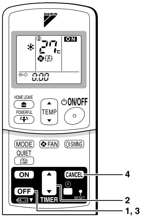
text_image
DAIKIN 717 ON 0:00 HOME LEAVE POWERFUL TEMP ON/OFF MODE FAN SWING QUIET ON CANCEL OFF TIMER RESET 4 2 1, 3■ To cancel the OFF TIMER operation
4. Press "CANCEL button".
• The TIMER lamp goes off.
NOTE
- When TIMER is set, the present time is not displayed.
- Once you set ON, OFF TIMER, the time setting is kept in the memory. (The memory is canceled when remote controller batteries are replaced.)
- When operating the unit via the ON/OFF Timer, the actual length of operation may vary from the time entered by the user. (Maximum approx. 10 minutes)
■ NIGHT SET MODE
When the OFF TIMER is set, the air conditioner automatically adjusts the temperature setting (0.5°C up in COOL, 2.0°C down in HEAT) to prevent excessive cooling (heating) for your pleasant sleep.
■ To use ON TIMER operation
- Check that the clock is correct. If not, set the clock to the present time
1. Press "ON TIMER button".
6:00 is displayed.
| blinks.
2. Press "TIMER Setting button" until the time setting reaches the point you like.
- Every pressing of either button increases or decreases the time setting by 10 minutes. Holding down either button changes the setting rapidly.
3. Press "ON TIMER button" again.
- The TIMER lamp lights up.

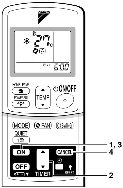
text_image
DAIKIN 7:17 2°C 6:00 HOME LEAVE POWERFUL TEMP ON/OFF MODE FAN SWING QUIET ON CANCEL OFF TIMER RESET 1, 3 4 2■ To cancel ON TIMER operation
4. Press "CANCEL button".
- The TIMER lamp goes off.
■ To combine ON TIMER and OFF TIMER
- A sample setting for combining the two timers is shown below.
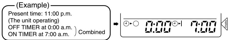
text_image
(Example) Present time: 11:00 p.m. (The unit operating) OFF TIMER at 0:00 a.m. ) ON TIMER at 7:00 a.m. ) Combined → ④▶○ 7.77④▶1 7.77 4.241 7.441 CircuitsATTENTION
■ In the following cases, set the timer again.
• After a breaker has turned OFF.
• After a power failure.
• After replacing batteries in the remote controller.
2.3.9 Note for Multi System
Note for Multi System
<< What is a "Multi System"? >>
This system has one outdoor unit connected to multiple indoor units.
■ Selecting the Operation Mode
1. With the Priority Room Setting present but inactive or not present.
When more than one indoor unit is operating, priority is given to the first unit that was turned on.
In this case, set the units that are turned on later to the same operation mode (*1) as the first unit.
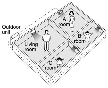
text_image
Outdoor unit Living room A room B room C roomOtherwise, they will enter the Standby Mode, and the operation lamp will flash; this does not indicate malfunction. (*1)
• COOL, DRY and FAN mode may be used at the same time.
- AUTO mode automatically selects COOL mode or HEAT mode based on the room temperature. Therefore, AUTO mode is available when selecting the same operation mode as that of the room with the first unit to be turned on.
Normally, the operation mode in the room where the unit is first run is given priority, but the following situations are exceptions, so please keep this in mind.
If the operation mode of the first room is FAN Mode, then using Heating Mode in any room after this will give priority to heating. In this situation, the air conditioner running in FAN Mode will go on standby, and the operation lamp will flash.
2. With the Priority Room Setting active.
See "Priority Room Setting" on the next page.
■ NIGHT QUIET Mode (Available only for cooling operation)
NIGHT QUIET Mode requires initial programming during installation. Please consult your retailer or dealer for assistance. NIGHT QUIET Mode reduces the operation noise of the outdoor unit during the night time hours to prevent annoyance to neighbors.
- The NIGHT QUIET Mode is activated when the temperature drops 5^ or more below the highest temperature recorded that day. Therefore, when the temperature difference is less than 5^ , this function will not be activated.
- NIGHT QUIET Mode reduces slightly the cooling efficiency of the unit.
■ OUTDOOR UNIT QUIET Operation
1. With the Priority Room Setting present but inactive or not present.
When using the OUTDOOR UNIT QUIET operation feature with the Multi system, set all indoor units to OUTDOOR UNIT QUIET operation using their remote controllers.
When clearing OUTDOOR UNIT QUIET operation, clear one of the operating indoor units using their remote controller. However OUTDOOR UNIT QUIET operation display remains on the remote controller for other rooms.
We recommend you release all rooms using their remote controllers.
2. With the Priority Room Setting active.
See "Priority Room Setting" on the next page.
■ Cooling / Heating Mode Lock (Available only for heat pump models)
The Cooling / Heating Mode Lock requires initial programming during installation. Please consult your retailer or dealer for assistance. The Cooling / Heating Mode Lock sets the unit forcibly to either Cooling or Heating Mode. This functions convenient when you wish to set all indoor units connected to the Multi system to the same operation mode.
■ Priority Room Setting
The Priority Room Setting requires initial programming during installation. Please consult your retailer or dealer for assistance.
The room designated as the Priority Room takes priority in the following situations;
1. Operation Mode Priority.
As the operation mode of the Priority Room takes precedence, the user can select a different operation mode from other rooms.
* Room A is the Priority Room in the examples.
When COOL mode is selected in Room A while operating the following modes in Room B,C and D:
| Operation mode in Room B, C and D | Status of Room B, C and D when the unit in Room A is in COOL mode |
| COOL or DRY or FAN | Current operation mode maintained |
| HEAT | The unit enters Standby Mode. Operation resumes when the Room A unit stops operating. |
| AUTO | If the unit is set to COOL mode, operation continues. If set to HEAT mode, it enters Standby Mode. Operation resumes when the Room A unit stops operating. |
2. Priority when POWERFUL operation is used.
* Room A is the Priority Room in the examples.
The indoor units in Rooms A,B,C and D are all operating. If the unit in Room A enters POWERFUL operation, operation capacity will be concentrated in Room A. In such a case, the cooling (heating) efficiency of the units in Rooms B,C and D may be slightly reduced.
3. Priority when using OUTDOOR UNIT QUIET operation.
* Room A is the Priority Room in the examples.
Just by setting the unit in Room A to QUIET operation, the air conditioner starts OUTDOOR UNIT QUIET operation.
You don't have to set all the operated indoor units to QUIET operation.
3. SA Indoor Unit
3.1 BRC1D528
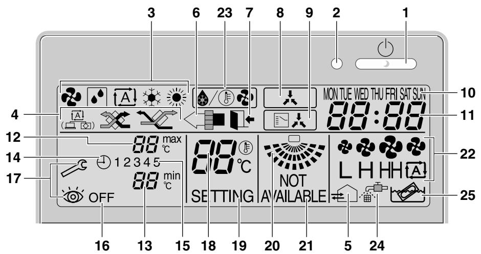
text_image
3 6 23 7 8 9 2 1 MON TUE WED THU FRI SAT SUN 88:88 4 10 12 11 88 max °C 88°C 22 14 12 3 4 5 NOT L H H H A 17 88 min °C SETTING AVAILABLE OFF 16 13 15 18 19 20 21 5 24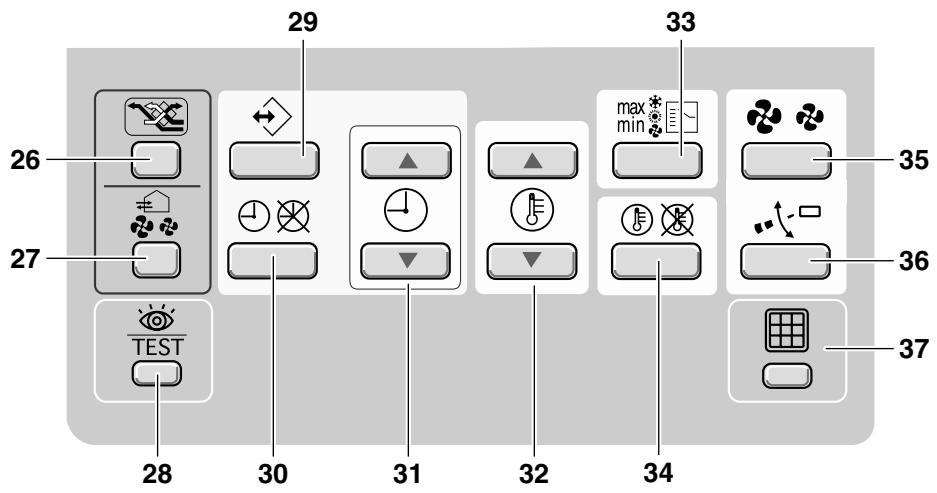
text_image
26 27 TEST 28 30 31 32 34 35 36 37 29 331
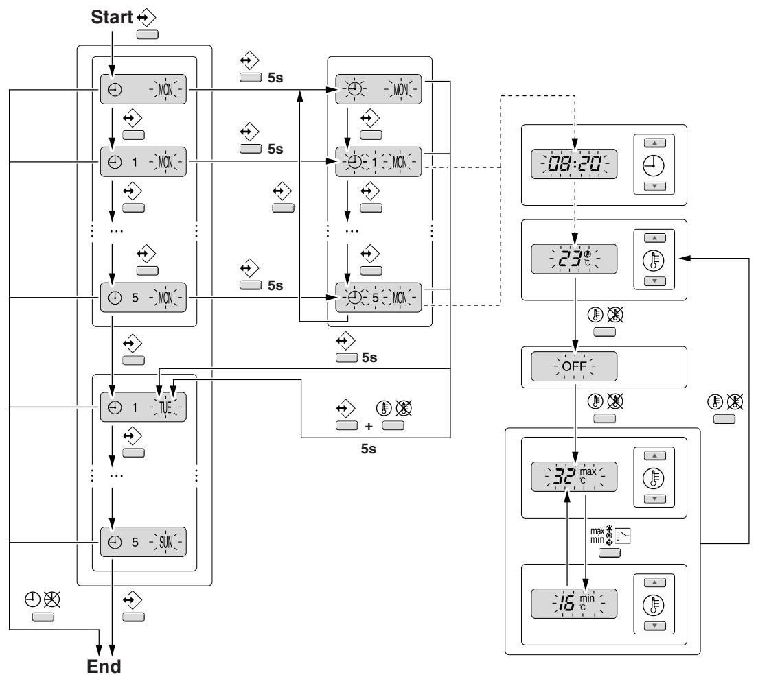
flowchart
graph TD
    A["Start"] --> B["MON"]
    B --> C["1 MON"]
    C --> D["..."]
    D --> E["5 MON"]
    E --> F["TUE"]
    F --> G["SUN"]
    G --> H["End"]
    B --> I["MON"]
    I --> J["1 MON"]
    J --> K["..."]
    K --> L["5 MON"]
    L --> M["TUE"]
    M --> N["SUN"]
    N --> O["End"]
    I --> P["MON"]
    P --> Q["1 MON"]
    Q --> R["..."]
    R --> S["5 MON"]
    S --> T["TUE"]
    T --> U["SUN"]
    U --> V["End"]
    style A fill:#f9f,stroke:#333
    style V fill:#bbf,stroke:#333
2

BRC1D528
Remote controller
Operation manual

THANK YOU FOR PURCHASING THIS CONTROLLER. READ THE MANUAL ATTENTIVELY BEFORE USING THE INSTALLATION. AFTER READING THE MANUAL, STORE IT IN A SAFE PLACE FOR FUTURE USE.

Before initial operation, contact your dealer to obtain all details concerning your air conditioning installation.
WARNING
- Never let the remote controller get wet, this may cause an electric shock or fire.
- Never press the buttons of the remote controller with a hard, pointed object. The remote controller may be damaged.
- Never inspect or service the remote controller yourself, ask a qualified service person to do this.
Contents
page
- Features and functions....1
- Name and function of switches and icons......2
- Setting up the controller....4
- Description of the operation modes.....5
- Operation....5
- Programming the schedule timer....10
1. Features and functions
The BRC1D528 is a state of the art remote controller that offers full control over your installation.
1 BASIC REMOTE CONTROLLER
The basic remote controller functions are:
- ON/OFF,
• operation mode change-over,
• temperature adjustment,
• air volume adjustment
• air flow direction adjustment.
2 CLOCK FUNCTION
The clock functions are:
• 24 hours real time clock,
• day of the week indicator.
3 SCHEDULE TIMER FUNCTION
The schedule timer functions are:
• a maximum of 5 actions can be programmed for each day of the week (totalling 35 actions),
- schedule timer can be enabled/disabled at any time,
- linked to a set temperature or a LIMIT operation or an OFF operation,
- "last command" overrules previous command until next scheduled command.
4 LIMIT OPERATION
Limit operation provides thermostat control within the range of the set minimum and maximum temperature. The minimum temperature setting will trigger heating, the maximum temperature setting will trigger cooling.
Operation manual
1
DAIKIN
BRC1D528
Remote controller
4PW23717-1
5 LEAVE HOME
The leave home function prevents the room temperature from dropping when the occupants are out for a longer period. If the room temperature drops below 10^ C, heating is started automatically. As soon as 15^ C is reached, the controller returns to its original status.
Three hierarchical permission levels can be set to limit the user action.
2. Name and function of switches and icons (Refer to figure 1)
1 ON/OFF BUTTON

Press the ON/OFF button to start or stop the system.
2 OPERATION LAMP ○
The operation lamp lights up during operation or blinks if a malfunction occurs.
These icons indicate the current operation mode (FAN, DRY, AUTOMATIC, COOLING, HEATING).
4 VENTILATION MODE ICON

These icons indicate the current ventilation mode (HRV only) (AUTOMATIC, HEAT EXCHANGE, BYPASS).
5 VENTILATION ICON

The ventilation icon appears when the ventilation is adjusted with the ventilation amount button (HRV only). Simultaneously, the ventilation amount is indicated by the fan speed icon (see 22).
6 AIR CLEANING ICON

This icon indicates that the air cleaning unit (option) is operational.
7 LEAVE HOME ICON

The leave home icon shows the status of the leave home function.
| ON | Leave home is enabled |
| FLASHING | Leave home is active |
| OFF | Leave home is disabled |
8 EXTERNAL CONTROL ICON
This icon indicates that another controller with higher priority is controlling or disabling your installation.
9 CHANGE-OVER UNDER CENTRALISED CONTROL ICON
This icon indicates that the change-over of the installation is under centralised control assigned to another indoor unit or optional cool/heat selector connected to the outdoor unit (= master remote controller).
10 DAY OF THE WEEK INDICATOR MON TUE WED THU FRI SAT SUN
The day of the week indicator shows the current week day (or the set day when reading or programming the schedule timer).
11 CLOCK DISPLAY 88:88
The clock display indicates the current time (or the action time when reading or programming the schedule timer).
BRC1D528
Remote controller
4PW23717-1
DAIKIN
Operation manual
12 MAXTEMPERATURE IMUM SET 88 max °C
The maximum set temperature indicates the maximum set temperature when in limit operation.
13 MINIMUM SET TEMPERATURE 88 min ℃
The minimum set temperature indicates the minimum set temperature when in limit operation.
14 SCHEDULE TIMER ICON ⏻
This icon indicates that the schedule timer is enabled.
15 ACTION ICONS 1 2 3 4 5
These icons indicate the actions for each day of the schedule timer.
16 OFF ICON OFF
This icon indicates that the OFF action is selected when programming the schedule timer.
17 INSPECTION REQUIRED and
These icons indicate that inspection is required. Consult your installer.
18 SET TEMPERATURE DISPLAY 88 ^ ℃
This indicates the current set temperature of the installation (not shown in LIMIT operation or in FAN or DRY mode).
19 SETTING SETTING
Not used, for service purposes only.
20 AIR FLOW DIRECTION ICON
This icon indicates the air flow direction (only for installations with motorised air flow Baps).
21 NOT AVAILABLE NOT AVAILABLE
NOT AVAILABLE is displayed whenever a non-installed option is addressed or a function is not available.
22 FAN SPEED ICON L H H H A
This icon indicates the set fan speed.
23 DEFROST/HOTSTART MODE ICON
This icon indicates that the defrost/hotstart mode is active.
24 AIR FILTER CLEANING TIME ICON
This icon indicates the air filter must be cleaned. Refer to the manual of the indoor unit.
25 ELEMENT CLEANING TIME ICON
This icon indicates the element must be cleaned (HRV only).
26 VENTILATION MODE BUTTON
The ventilation mode button operates the HRV; refer to the HRV manual for more details.
27 VENTILATION AMOUNT BUTTON
This button sets the ventilation amount; refer to the HRV manual for more details.
Not used, for service purposes only.
29 PROGRAMMING BUTTON
This button is a multi-purpose button.
Depending on the previous manipulations of the user, the programming button can have various functions.
Operation manual
3
DAIKIN
BRC1D528
Remote controller
4PW23717-1
30 SCHEDULE TIMER BUTTON ⏻
This button enables or disables the schedule timer.
31 TIME ADJUST BUTTON ⏻ ▲ ⏻ ▼
These buttons are used to adjust the clock or, when in programming mode, to adjust the programmed action time. Both buttons have an auto-repeat function.
32 TEMPERATURE ADJUST BUTTONS
# ▲ #
These buttons are used to adjust the current setpoint or, when in programming mode, to adjust the programmed setpoint temperature (step = 1°C). Both buttons are also used to adjust the day of the week.
This button is a multi-purpose button. Depending on the previous manipulations of the user, it can have following functions:
1 select the operation mode of the installation (FAN, DRY, AUTOMATIC, COOLING, HEATING)
2 toggle between minimum temperature and maximum temperature when in limit operation
34 SETPOINT/LIMIT BUTTON
This button toggles between setpoint, limit operation or OFF (programming mode only).
35 FAN SPEED BUTTON
This button toggles between L (Low), H (High), HH (very High), ☑ (Automatic).
36 AIR FLOW DIRECTION ADJUST BUTTON
This button enables to adjust the air flow direction.
37 AIR FILTER CLEANING TIME ICON RESET
BUTTON
This button is used to reset the air filter cleaning time icon.
3. Setting up the controller
After initial installation, the user can set the clock and day of the week.
The controller is equipped with a schedule timer that enables the user to operate the installation automatically; setting the clock and day of the week is required to be able to use the schedule timer.
1 CLOCK SETTING FUNCTION
Hold down the ⏻ button for 5 seconds. The clock read-out and the day of week indicator will blink, both can now be adjusted.
Use the ⊕▲ & ⊕▼ buttons to adjust the clock. Each time pressing the time adjust button will in/decrease the time by 1 minute. Keeping the ⊕▲ or ⊕▼ button pressed will in/decrease the time by 10 minutes.
Use the Ⓗ ▲ & Ⓗ ▼ buttons to adjust the day of the week. Each time pressing the Ⓗ ▲ or Ⓗ ▼ buttons will display the next or previous day. Press the ◆ button to confirm the current set time and day of the week.
If the controller, with blinking clock and day of week read-out, is left untouched for 5 minutes, the clock and day of the week will return to their previous settings; the clock setting function is no longer active.
2 SETTING UP THE SCHEDULE TIMER
To set up the schedule timer, refer to chapter 6. "Programming the schedule timer" on page 10.
BRC1D528
Remote controller
4PW23717-1
DAIKIN
Operation manual
4
4. Description of the operation modes
In this mode, air only circulates without heating or cooling.
2 DRY OPERATION
In this mode, the air humidity will be lowered with a minimal temperature decrease.
The temperature and fan speed are controlled automatically and cannot be controlled by the remote controller.
Dry operation will not function if the room temperature is too low.
In this mode, the controller will automatically switch between heating and cooling as required by the setpoint or limit temperature.
4 COOLING OPERATION
In this mode, cooling will be activated as required by the setpoint or limit temperature.
5 HEATING OPERATION
In this mode, heating will be activated as required by the setpoint or limit temperature.
Hot start (heat pump types only)
At the start of a heating operation, the indoor fan is stopped until a certain indoor heat exchanger temperature is reached and 🏠/ respiratory is displayed. This prevents cold air from leaving the indoor unit.
Defrost (heat pump types only)
In heating operation, freezing of the outdoor heat exchanger may occur. If so, the heating capacity of the system lowers and the system goes into defrost operation. The indoor unit fan stops and is displayed. After maximum 10 minutes of defrost operation, the system returns to heating operation again.
6 LIMIT OPERATION ^min & ^max
Limit operation is an additional mode that enables to keep the room temperature within certain limits. The _℃ & _℃ icons are displayed to confirm the activation of the limit operation.
7 LEAVE HOME
LEAVE HOME is a feature that enables to keep the room temperature above 10^ C when the occupants are out. This function will switch on heating if the installation is switched off.
5. Operation
Manual operation
In manual operation, the user decides about the settings of the installation. The last setting remains active until the user changes it.
As the controller can be implemented for a wide variety of installations and features, it might occur that you select a function that is not available on your installation; if this is the case, the NOT message will appear.
Operation manual
5
DAIKIN
BRC1D528
Remote controller
4PW23717-1
Use the max * * button to select the desired operation mode.
| Fan only operation | |
| Dry operation | |
| Automatic operation | |
| Cooling operation | |
| Heating operation |
Press the ⏻ button to toggle between limit operation and the operations listed above.
In limit operation, use the max min + button to select minimum and maximum temperature settings. Use the □ or ▼ buttons to adjust the minimum and maximum temperature settings.
Press the ⏻▲ and ⏻▼ buttons simultaneously to enable the LEAVE HOME function.

KEEP IN MIND THAT THE ⏻ BUTTON MUST BE OFF TO GUARANTEE TRIGGERING OF THE LEAVE HOME FUNCTION.
2 Adjusting the air flow direction
Use the ⚡️ button to adjust the air flow direction. Press the button to switch between fixed or variable air flow direction. Use the ⚡️ icon to determine the fixed air flow direction by pressing the ⚡️ button when the ⚡️ icon indicates the desired direction.
NOTE

Even if fixed air flow direction is selected, variable air flow direction can be enabled automatically to preserve proper operation of your installation.
3 SCHEDULE TIMER
All features and operation and programming of the schedule timer are described below.
Schedule timer operation
In schedule timer operation, the installation is also controlled by the schedule timer. The actions programmed in the schedule timer will be executed automatically.
The schedule timer always executes the last command; this means the user can temporarily overrule the last executed programmed action. Refer to "Manual operation" on page 5. The next programmed action (in the schedule timer) will return control to the schedule timer.
Use the ⏻ button to enable or disable the schedule timer.
NOTE

The schedule timer overrules the button, only use the ⏻ button to enable or disable the schedule timer. The schedule timer is enabled when the icon is visible. The button only overrules the schedule timer until the next programmed action.

The programmed schedule is time driven. Make sure that the clock and day of the week are set correctly. Refer to "CLOCK SETTING FUNCTION" on page 4.

Manually adjust the clock for summertime and wintertime. Refer to "CLOCK SETTING FUNCTION" on page 4.

A power failure exceeding 1 hour will reset the clock and the day of the week. Refer to "CLOCK SETTING FUNCTION" on page 4 to adjust the clock and the day of the week. The actions programmed in the schedule timer will not be lost after a power failure; reprogramming the schedule timer is not required.
To set up the SCHEDULE TIMER refer to chapter 6. "Programming the schedule timer" on page 10.
Operation manual
7
DAIKIN
BRC1D528
Remote controller
4PW23717-1
What can the schedule timer do?
The concept of the schedule timer is simple, straightforward though powerful.
The schedule timer can order 3 actions:
1 switch on the installation at a scheduled time, in combination with a setpoint (exact temperature control)
2 switch off the installation (end of control)
3 switch on the installation at a scheduled time, in limit operation
The schedule timer can accept a maximum of 5 actions per day.
For each day of the week a maximum of 5 actions can be programmed, totalling a maximum of 35 programmed actions. The action that was programmed first for a certain day is action 1, the last programmed action for a day could be action 1 (in case only one action is programmed for that day) to 5.

It is of utmost importance to understand that the number assigned to the programmed action, DOES NOT DETERMINE WHEN the programmed action will be executed. Only the TIME, being a part of the data entered when programming the action, will determine when the programmed action will be executed.
What will the schedule timer do?
If enabled, the schedule timer will execute the programmed actions.
It will order the installation to:
• cool or heat, depending on the current operation, if applicable; the setpoint will be displayed,
OR
- switch off the installation (the schedule timer remains enabled and reactivates the installation as programmed); the operation lamp will turn off,
OR
• cool or heat, whichever is required to keep the room temperature within a specified range (limit operation); _C and _C are displayed.

The schedule timer will change the operation mode in LIMIT operation only.
To be able to verify the programmed actions, you can browse the programmed actions, see below.
What will the schedule timer NOT do?
The schedule timer will not:
• control fan speed,
• control air flow direction,
• control ventilation mode,
• control ventilation amount,
- change the operation mode for a scheduled setpoint.
The parameters listed above can be set manually, without interfering with the schedule timer.
More sophisticated remote controllers are available. Consult your dealer for more information.
Browsing the programmed actions in the schedule timer (read-out only)
Refer to figure 2.
Browsing the programmed actions of the schedule timer is a sequential process. Only 2 buttons are used to browse the entire schedule timer program.
The button is used to start browsing, to display the next programmed action or to exit browsing when displaying the last programmed action.
BRC1D528
Remote controller
4PW23717-1
DAIKIN
Operation manual
The ⏻ button is used to exit browsing at once (without having to scroll through all programmed actions).
Press the button to enter the browse mode, the icon appears, MON will blink.
NOTE

Browsing always starts on Monday and ends on Sunday.
Check the 12345 icon. If at least 1 action is programmed for Monday, 1 will appear.
The clock indicates the time when the programmed action is scheduled, either 24^ C, OFF or 16^ C and 30^ C is being displayed.
NOTE

The temperatures mentioned above are for clarifying purposes only, temperature values on your controller may vary.
If 1 does not appear, it indicates that there are no programmed actions for Monday.
Press the button again to go to the next day of the week. TUE will blink, this indicates that the programmed actions for Tuesday are being browsed.
The process described above is now restarted.
If at least 1 action is programmed for Tuesday, 1 will appear. The clock indicates the time when the programmed action will be enabled, either ^n^① ,
OFF or 16 min ^ C and 30 max ^ C is being displayed.
If 1 does not appear, it indicates that there are no programmed actions for Tuesday.
Press the button to display the next programmed action. If a second action is programmed for Tuesday, TUE will still be blinking and 12 will appear.
Assuming that 5 actions were programmed for Tuesday, a total of 5 presses will be required to display all programmed actions.
Continue pressing the button until the day of the week indicator displays the current day (not blinking), you have now quit browsing.
NOTE

The number of times that the button will have to be pressed to quit browsing depends on the number of programmed actions in the schedule timer.
How do I interpret the programmed actions
To be able to understand the behaviour of your installation when the schedule timer is enabled, it is important to look at all programmed actions for the current day and maybe the last programmed action of yesterday.
If the first programmed action for today is not active yet, the current status of your installation depends, most probably but not necessarily, on the last programmed action from yesterday. Read the important note below.
If the first programmed action for today is already active, the current status of your installation depends, most probably but not necessarily, on the parameters programmed in the first programmed action for today. Read the important note below.
NOTE

To keep the operation of your installation simple, the schedule timer settings can easily be overruled by altering the current setting ("last command" overrules previous command until next scheduled command).
Conclusion: Although ⊕ is displayed, somebody might have altered the settings. The next programmed action will overrule the altered settings and all settings return as programmed.
Operation manual
9
DAIKIN
BRC1D528
Remote controller
4PW23717-1
Programmed actions might overlap; due to the "last command overrules" logic, the last scheduled command will rule.
How do I interpret the readings on the display when the schedule timer is active
As described above, the schedule timer settings, (and as a consequence the display readings) might be overruled temporarily by a manual intervention. If you want to be absolutely sure about the schedule timer settings for this very moment, you must browse the schedule timer programmed actions. Refer to "Browsing the programmed actions in the schedule timer" on page 8.
6. Programming the schedule timer
What do I have to program?
As the schedule timer is based on a week program (the same actions will be repeated every week) you will have to select the day of the week first.
Now you must choose an action:
1 switch on the installation at a scheduled time, in combination with a setpoint (exact temperature control)
2 switch off the installation (end of control)
3 switch on the installation at a scheduled time, in limit operation
Finally you must enter the time of the day when the action must be enabled.
NOTE

If you program 2 or more actions on the same day and at the same time of the day, only the action with the highest action number (2 - 5) will be executed.
Getting started
Programming the schedule timer is flexible (you can add, remove or alter programmed actions whenever required) and straightforward (programming steps are limited to a minimum).
Below are some tips and tricks to ensure successful programming of the schedule timer:
- familiarise yourself with the icons and the buttons, you will need them when programming,
- familiarise yourself with the browse function, you will need it to start programming. Refer to "Browsing the programmed actions in the schedule timer" on page 8,
• fill out the form at the end of this manual; note the time and the required action for each day (keep in mind that the number of actions is limited to 5 per day),
• take your time to enter all data accurately, - try to program the actions for each day in logical sequence (start with action 1 for the first action and end with the highest number for the last action). This is not a requirement but it will make it much easier to interpret the program later,
- keep in mind that you can always alter, add or remove the programmed actions later.
BRC1D528
Remote controller
4PW23717-1
DAIKIN
Operation manual
10
Programming
1 THE SCHEDULE TIMER IS PROGRAMMED FOR THE FIRST TIME
NOTE

When changing day during programming you will have to confirm "the last action". Each day can have 5 programmed actions (numbered 1 to 5) but for some reason you might want to delete one, several or all programmed actions.
Tobe able to delete programmed actions, you must select the last action that you want to keep, this can be 1 to 5 or no action (⊕ is displayed and no action displayed).
All programmed actions with a number HIGHER than the selected one, or all programmed actions if no last action was selected will be deleted.
PROGRAMMING THE FIRST DAY OF THE WEEK
NOTE

In the guidelines below it is assumed that you start programming the schedule timer actions on Monday and end with the schedule timer actions for Sunday.
If you prefer NOT to start on Monday, first browse to the desired day and then enter the PROGRAM mode.
In this particular case, no actions have been programmed before, all schedule timer actions are idle.
- Browse to Monday by pressing the ➕ button. The ⊕ icon appears, MON will blink and one of the ⚙️ 🖱️ 📐 🌿 🌿 🌿 icons might be displayed but all other fields remain blank, indicating that no actions are programmed for Monday.
- Enter the program mode by holding down the button for 5 seconds, the ⏻ icon will now blink too.
- Press the button to activate the first programmed action.
- A blinking 1 is displayed indicating that the first programmed action for Monday is being programmed; The set temperature and clock display are blinking.
- Press the ⏻ button to select either set temperature, OFF, or limit operation.
- Enter the desired temperature using the ⏻ ▲ & ⏻ ▼ buttons.
- Press the max * * * * * * * * * * * * * * * * * * * * * * * * * * * * * * * * * * * * * * * * * * * * * * * * * * * * * * * * * * * * * * * * * * * * * * * * * * * * * * * * * * * * * * * * * * * * * * * * * * * *
- Enter the time when the action must start using the ⏻▲ & ⏻▼ buttons (min. step = 10 minutes).
NOTE

If, by accident, you pressed the button, you activated the next action; 12 is displayed (1 steady and 2 blinking). Press the button repeatedly until a blinking 1 is displayed. You can now continue adjusting the settings for the first schedule timer action.
Operation manual
11
DAIKIN
BRC1D528
Remote controller
4PW23717-1
If the action and the corresponding time are correct, you can proceed to the second schedule timer action. This is done by pressing the button, the data is saved and the next schedule timer action can be programmed.
Programming the remaining schedule timer actions for the same day is similar.
You can browse the schedule timer actions by pressing the ➕ button.
NOTE
Don't worry if you add additional schedule timer actions by pressing the button repeatedly, they can be deleted when finishing the current day.
When all data for the schedule timer actions for Monday are entered, you must confirm the programmed actions.
Make sure the last schedule timer action you want to keep is selected (schedule timer actions with a higher number will be deleted).
Now you must choose between 2 options:
1 CONFIRM AND COPY TO NEXT DAY
The schedule timer action programmed for the current day are also valid for the next day: use the "confirm last action and copy actions to next day" function by pressing the and buttons simultaneously for 5 seconds.
2 CONFIRM ONLY
The schedule timer action programmed for the current day are only valid for the selected day: use the "confirm last action and go to next day" function by pressing the button for 5 seconds.
Program mode is quit and depending on the choice made, the programmed actions are saved for Monday (and possibly Tuesday).
PROGRAMMING THE OTHER DAYS OF THE WEEK
Programming the other days of the week is identical to programming the first day of the week. TUE is blinking to indicate the selected day, ⊕ and 1 are steady if actions were copied from Monday to Tuesday, only ⊕ is displayed if no actions were copied from Monday to Tuesday.
2 I WANT TO EDIT PROGRAMMED ACTIONS Editing programmed actions is easy.
Make sure you are not in program mode (⊕ not blinking); if required, press the ⊕ button to quit program mode.
Browse to the programmed actions using the button, select the day and action you want to edit. Press the button for 5 seconds; program mode is enabled, the icon and selected action are blinking. Edit the settings using the same buttons described above.
Select the "last action" using the button and decide if you do or do not want to copy the programmed action(s) to the next day (pressing the and buttons simultaneously or only the button for 5 seconds).
BRC1D528
Remote controller
4PW23717-1
DAIKIN
Operation manual
12
3 I WANT TO DELETE ONE OR MORE PROGRAMMED ACTIONS
Make sure you are not in program mode ( ① not blinking); if required, press ② to quit program mode.
Browse to the programmed actions using the button, select the day you want to edit.
Press the button for 5 seconds; program mode is enabled, the icon and selected action are blinking. Select the "last action" you want to keep using the button. All higher actions will be deleted.
Confirm the deletion by pressing the button for 5 seconds, OR confirm the deletion for the current and the next day too by pressing the and & buttons simultaneously for 5 seconds.
NOTE

In the case above, if for example the last action was 3, the programmed actions 4 and 5 will also be deleted (if they were present).
4 I WANT TO DELETE ALL PROGRAMMED ACTIONS AT ONCE
Quit programming or browsing.
Press the and buttons simultaneously for 5 seconds; the icon will invert and disappear to confirm deletion.
7. Maintenance
The remote controller does not need maintenance. Remove dirt with a soft damp cloth.
NOTE

Only use clear tepid water to moisten the cloth.
8. Troubleshooting
The guidelines below might help to solve your problem. If you cannot remedy the problem, consult your installer.
No readings on the remote controller (display blank)
Check if the mains power is still applied to your installation.
Only 88 is displayed
This indicates that the installation has just been powered, please wait until 88 disappears.
The schedule timer does work but the programmed actions are executed at the wrong time (e.g. 1 hour too late or too early)
Check if the clock and the day of the week are set correctly, correct if necessary (refer to "CLOCK SETTING FUNCTION" on page 4).
I cannot enable the schedule timer (the ⏻ icon blinks for 2 seconds and disappears)
The schedule timer has not been programmed yet. First program the schedule timer (refer to "Programming the schedule timer" on page 10).
I cannot enable the schedule timer (the NOT AVAILABLE icon is displayed)
The schedule timer can not be enabled when a centralised control is connected.
Limit operation cannot be selected
Limit operation is not available for cooling only installations.
Operation manual
13
DAIKIN
BRC1D528
Remote controller
4PW23717-1
4PW23717-1
Part 6
Service Diagnosis
1. Troubleshooting with LED....250
1.1 Indoor Unit....250
1.2 Outdoor Unit 252
2. Problem Symptoms and Measures....253
3. Service Check Function 254
3.1 RA Indoor Unit - FTXG, FTXS, CTXS, FVXG, FVXS, FLXS, FDXS Series....254
3.2 SA Indoor Unit - FCQG, FFQ, FHQ, FDBQ, FBQ Series .....263
4. Code Indication on Remote Controller 267
4.1 RA Indoor Unit - FTXG, FTXS, CTXS, FVXG, FVXS, FLXS, FDXS Series....267
4.2 SA Indoor Unit - FCQG, FFQ, FHQ, FDBQ, FBQ Series .....267
4.3 Sub Codes for SA Indoor Unit 268
4.4 Outdoor Unit 269
5. Troubleshooting for RA Indoor Unit - FTXG, FTXS, CTXS, FVXG, FVXS, FLXS, FDXS Series 270
5.1 Indoor Unit PCB Abnormality 270
5.2 Freeze-up Protection Control or Heating Peak-cut Control......272
5.3 Fan Motor or Related Abnormality ....274
5.4 Radiant Panel Temperature Rise, Indoor Electronic Expansion Valve (Motor Operated Valve) Abnormality, Freeze-up Protection Control (FVXG Series Only)....278
5.5 Thermistor or Related Abnormality (RA Indoor Unit)....280
5.6 Front Panel Open / Close Fault (FTXG Series Only) 281
5.7 Signal Transmission Error (between Indoor Unit and Outdoor Unit) ....282
5.8 Unspecified Voltage (between Indoor Unit and Outdoor Unit) .....283
6. Troubleshooting for SA Indoor Unit - FCQG, FFQ, FHQ, FDBQ, FBQ Series....284
6.1 Indoor Unit PCB Abnormality 284
6.2 Drain Water Level System Abnormality....285
6.3 Fan Motor or Related Abnormality .....287
6.4 Swing Motor Lock (FHQ Series Only) 289
6.5 Drain System Abnormality....290
6.6 Thermistor or Related Abnormality (SA Indoor Unit)....291
6.7 Remote Controller Thermistor Abnormality 292
6.8 Signal Transmission Error
(between Indoor Unit and Remote Controller)....293
6.9 Signal Transmission Error
(between MAIN Remote Controller and SUB Remote Controller)......294
6.10 Field Setting Abnormality .....295
7. Troubleshooting for Outdoor Unit....296
7.1 Refrigerant Shortage....296
7.2 Low-voltage Detection or Over-voltage Detection.....298
7.3 Signal Transmission Error (on Outdoor Unit PCB)....300
7.4 Unspecified Voltage (between Indoor Unit and Outdoor Unit) / Anti-icing Function in Other Rooms....301
7.5 Anti-icing Function....302
7.6 Outdoor Unit PCB Abnormality....304
7.7 OL Activation (Compressor Overload) 305
7.8 Compressor Lock 306
7.9 DC Fan Lock 307
7.10 Input Overcurrent Detection 308
7.11 Discharge Pipe Temperature Control....309
7.12 High Pressure Control in Cooling 310
7.13 Compressor Sensor System Abnormality ....311
7.14 Position Sensor Abnormality ....313
7.15 CT or Related Abnormality 315
7.16 Thermistor or Related Abnormality (Outdoor Unit)....317
7.17 Electrical Box Temperature Rise....319
7.18 Radiation Fin Temperature Rise 321
7.19 Output Overcurrent Detection 323
8. Check....325
8.1 Thermistor Resistance Check 325
8.2 Fan Motor Connector Check 326
8.3 Hall IC Check 327
8.4 Indoor Electronic Expansion Valve Coil Check 327
8.5 Power Supply Waveform Check....328
8.6 Outdoor Electronic Expansion Valve Check 329
8.7 Four Way Valve Performance Check....330
8.8 Inverter Unit Refrigerant System Check....330
8.9 "Inverter Checker" Check 331
8.10 Rotation Pulse Check on the Outdoor Unit PCB 332
8.11 Installation Condition Check....333
8.12 Discharge Pressure Check....333
8.13 Outdoor Fan System Check....334
8.14 Capacitor Voltage Check....334
8.15 Power Module Check....335
1. Troubleshooting with LED
1.1 Indoor Unit
Operation Lamp
The operation lamp blinks when any of the following errors is detected.
- When a protection device of the indoor or outdoor unit is activated, or when the thermistor malfunctions.
- When a signal transmission error occurs between the indoor and outdoor units. In either case, conduct the diagnostic procedure described in the following pages.
Wall Mounted Type: FTXG Series
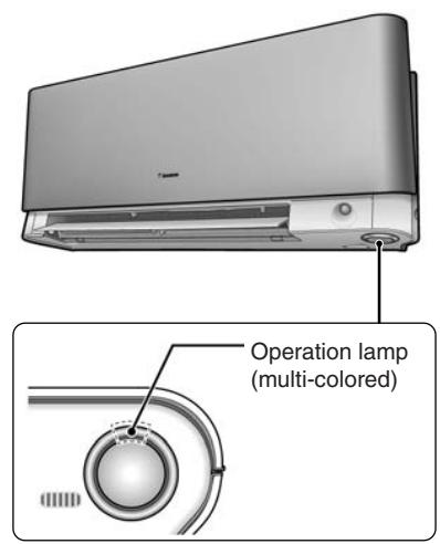
text_image
Operation lamp (multi-colored)(R12750)
Wall Mounted Type: FTXS-K, CTXS-K Series
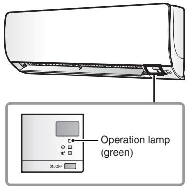
text_image
Operation lamp (green) ON/OFF(R17161)
Wall Mounted Type: FTXS-J Series
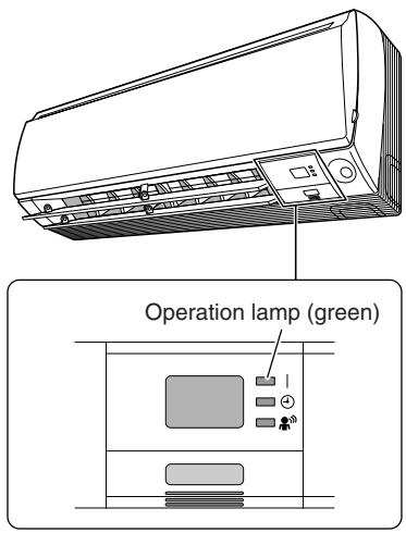
text_image
Operation lamp (green)(R12187)
Wall Mounted Type: FTXS-G Series
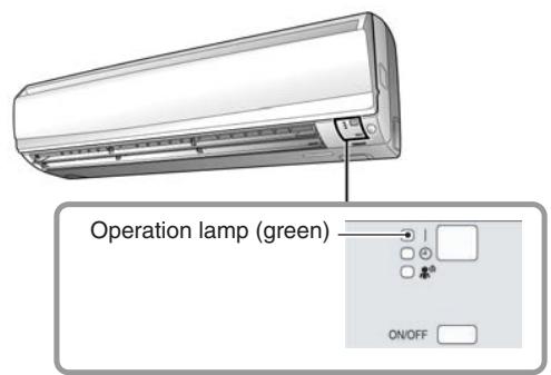
text_image
Operation lamp (green) ON/OFF(R16008)
Floor Standing Type: FVXG Series
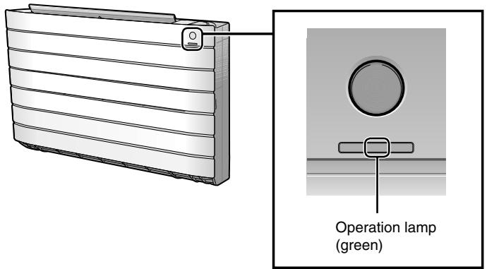
text_image
Operation lamp (green)(R14646)
Floor Standing Type: FVXS Series
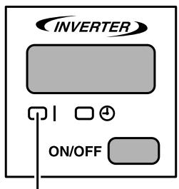
text_image
INVERTER ON/OFFOperation lamp (green)
(R11687)
Floor / Ceiling Suspended Dual Type
text_image
Operation lamp (green) DAIKIN < INVERTER > R11688Duct Connected Type
text_image
Operation lamp (green) Q0340BRC1D528
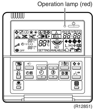
text_image
Operation lamp (red) OFF 12345 88 ℃ 88 ℃ 60℃ NOT L H H A SETTING AVAILABLE R12851BRC1E52A7, BRC1E52B7
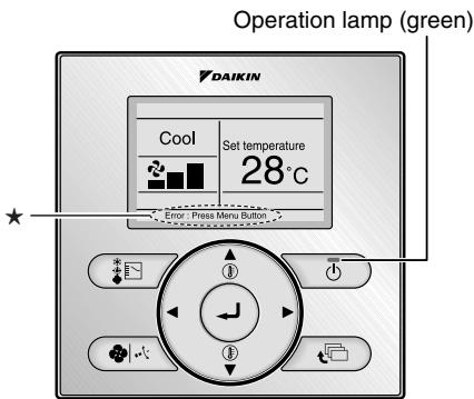
text_image
Operation lamp (green) DAIKIN Cool Set temperature 28°C Error Press Menu Button ① ② ③★ The error or warning message also blinks on the basic screen.
(R17162)

Caution:
When operation stops suddenly and the operation lamp blinks, it could be "operation mode conflict".
Check followings;
Are the operation modes all the same for the indoor units connected to multi system outdoor unit?
If not, set all the indoor units to the same operation mode and confirm that the operation lamp is not blinking.
Moreover, when the operation mode is automatic, set all the indoor unit operation mode as "cooling" or "heating" and check again if the operation lamp is normal.
If the lamp stops blinking after the above steps, there is no malfunction.
* Operation stops and operation lamp blinks only for indoor unit which different operation mode is set later. (The first set operation mode has priority.)
Service Monitor
The indoor unit has one green LED (LED A) on the control PCB. When the microcomputer works in order, the LED A blinks.
1.2 Outdoor Unit
The outdoor unit has one green LED (LED A) on the PCB. When the LED A blinks, the microcomputer works in order.
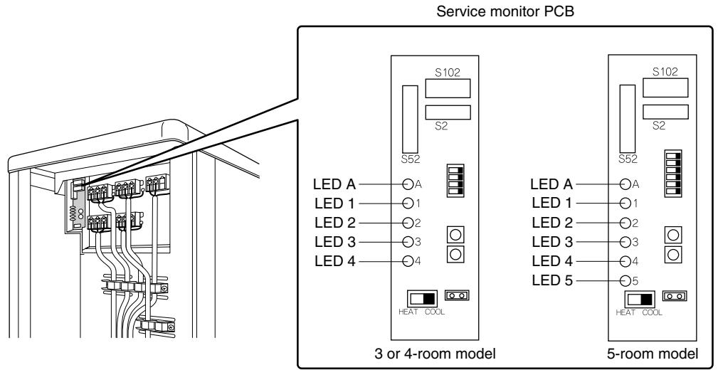
text_image
Service monitor PCB S102 S2 S52 LED A —○A LED 1 —○1 LED 2 —○2 LED 3 —○3 LED 4 —○4 HEAT COOL S102 S2 S52 LED A —○A LED 1 —○1 LED 2 —○2 LED 3 —○3 LED 4 —○4 LED 5 —○5 HEAT COOL 3 or 4-room model 5-room model(R17270)
There are a green LED (LED A) and red LEDs on the outdoor unit PCB. The LED A indicates microcomputer operation condition. In normal condition, the LED A is blinking and the other LEDs are OFF.
Even after the error is canceled and the unit operates in normal condition, the LED indication remains.
- Problem Symptoms and Measures
| Problem Symptom | Check Item | Details of Measure | Reference Page |
| None of the units operates. | Check the power supply. | Check if the rated voltage is supplied. | — |
| Check the types of the indoor units. | Check if the indoor unit type is compatible with the outdoor unit. | — | |
| Check the outdoor temperature. | Heating operation cannot be used when the outdoor temperature is 20°C or higher, and cooling operation cannot be used when the outdoor temperature is below -10 ~ 10°C (depending on the model). | — | |
| Diagnose with remote controller indication | — | 267 | |
| Check the remote controller addresses. | Check if address settings for the remote controller and indoor unit are correct. | 415 | |
| Operation sometimes stops. | Check the power supply. | A power failure of 2 to 10 cycles can stop air conditioner operation. (Operation lamp OFF) | — |
| Check the outdoor temperature. | Heating operation cannot be used when the outdoor temperature is 20°C or higher, and cooling operation cannot be used when the outdoor temperature is below -10 ~ 10°C (depending on the model). | — | |
| Diagnose with remote controller indication. | — | 267 | |
| Some indoor units do not operate. | Check the type of the indoor units. | Check if the indoor unit type is compatible with the outdoor unit. | — |
| Diagnose with remote controller indication | — | 267 | |
| Units operate but do not cool, or do not heat. | Check for wiring and piping errors in the connection between the indoor and outdoor units. | Conduct the wiring/piping error check described on the product diagnosis nameplate. | — |
| Check for thermistor detection errors. | Check if the thermistor is mounted securely. | — | |
| Check for faulty operation of the outdoor electronic expansion valve. | Set all the units to cooling operation, and compare the temperatures of the liquid pipes to see if the each outdoor electronic expansion valve works. | — | |
| Diagnose with remote controller indication. | — | 267 | |
| Diagnose by service port pressure and operating current. | Check for refrigerant shortage. | 296 | |
| Large operating noise and vibrations | Check the output voltage of the power module. | — | 335 |
| Check the power module. | — | — | |
| Check the installation condition. | Check if the required spaces for installation (specified in the installation manual) are provided. | — |
3. Service Check Function
3.1 RA Indoor Unit - FTXG, FTXS, CTXS, FVXG, FVXS, FLXS, FDXS Series
3.1.1 ARC466 Series Remote Controller
Check Method 1
- When the timer cancel button is held down for 5 seconds, 00 is displayed on the temperature display screen.
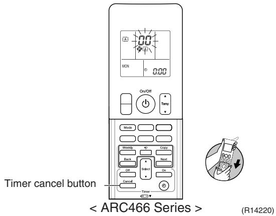
text_image
Timer cancel button < ARC466 Series > (R14220)- Press the timer cancel button repeatedly until a long beep sounds.
■ The code indication changes in the sequence shown below.
| No. | Code | No. | Code | No. | Code |
| 1 | 00 | 13 | 07 | 25 | 08 |
| 2 | 04 | 14 | 83 | 26 | 04 |
| 3 | 15 | 15 | 88 | 27 | 44 |
| 4 | 86 | 16 | 89 | 28 | 13 |
| 5 | 86 | 17 | 09 | 29 | 14 |
| 6 | 80 | 18 | 04 | 30 | 07 |
| 7 | 86 | 19 | 05 | 31 | 42 |
| 8 | 07 | 20 | 03 | 32 | 88 |
| 9 | 00 | 21 | 06 | 33 | 84 |
| 10 | F3 | 22 | 05 | 34 | 88 |
| 11 | 85 | 23 | 81 | 35 | 81 |
| 12 | F6 | 24 | 81 | 36 | 89 |
| No. | Code | No. | Code | No. | Code |
| 1 | 00 | 14 | 07 | 27 | 08 |
| 2 | 04 | 15 | 83 | 28 | 09 |
| 3 | 15 | 16 | 88 | 29 | 94 |
| 4 | 86 | 17 | 89 | 30 | 13 |
| 5 | 86 | 18 | 09 | 31 | 14 |
| 6 | 80 | 19 | 04 | 32 | 97 |
| 7 | 86 | 20 | 05 | 33 | 02 |
| 8 | 07 | 21 | 06 | 34 | 88 |
| 9 | 00 | 22 | 03 | 35 | 84 |
| 10 | F3 | 23 | 06 | 36 | 88 |
| 11 | 85 | 24 | 05 | 37 | 81 |
| 12 | F6 | 25 | 01 | 38 | 99 |
| 13 | 89 | 26 | 01 |

Note:
- A short beep and two consecutive beeps indicate non-corresponding codes.
- To return to the normal mode, hold the timer cancel button down for 5 seconds. When the remote controller is left untouched for 60 seconds, it also returns to the normal mode.
- Not all the error codes are displayed. When you cannot find the error code, try the check method 2. ( Refer to page 255.)
Check Method 2
- Press the center of the [Temp] button and the [Mode] button at the same time.
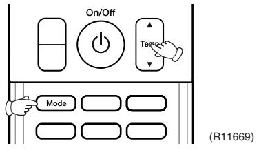
text_image
On/Off Timer Mode (R11669)SC is displayed on the LCD.
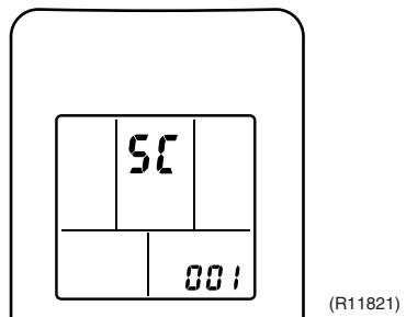
text_image
5C 001 (R11821)- Select SC (service check) with the [Temp] ▲ or ▼ button.
- Press the [Mode] button to enter the service check mode.
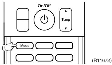
text_image
On/Off Temp Mode (R11672)The left-side number blinks.
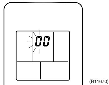
text_image
00 (R11670)- Press the [Temp] ▲ or ▼ button and change the number until you hear the two consecutive beeps or the long beep.
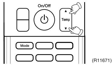
text_image
On/Off Temp Mode (R11671)- Diagnose by the sound.
★beep : The left-side number does not correspond with the error code.
★tow consecutive beeps : The left-side number corresponds with the error code but the right-side number does not.
★long beep : Both the left-side and right-side numbers correspond with the error code. The numbers indicated when you hear the long beep are the error code. Error codes and description → Refer to page 267.
- Press the [Mode] button.
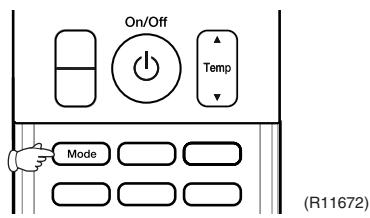
text_image
On/Off Temp Mode (R11672)The right-side number blinks.
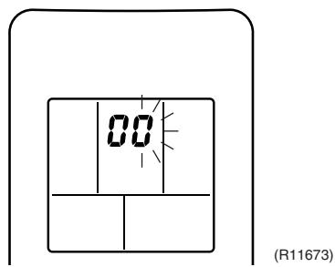
text_image
00 (R11673)- Press the [Temp] ▲ or ▼ button and change the number until you hear the long beep.
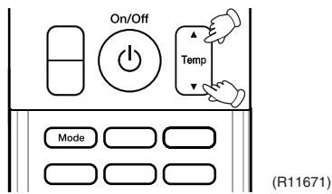
text_image
On/Off Temp Mode (R11671)- Diagnose by the sound.
★beep : The left-side number does not correspond with the error code.
★two consecutive beeps : The left-side number corresponds with the error code but the right-side number does not.
★long beep : Both the left-side and right-side numbers correspond with the error code.
- Determine the error code.
The numbers indicated when you hear the long beep are the error code.
Error codes and description → Refer to page 267.
- Press the [Mode] button for 5 seconds to exit from the service check mode.
(When the remote controller is left untouched for 60 seconds, it returns to the normal mode also.)
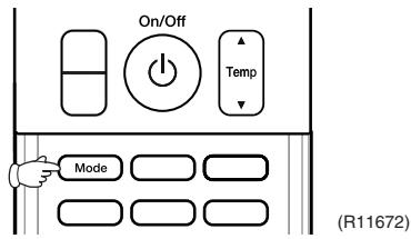
text_image
On/Off Temp Mode (R11672)3.1.2 ARC452 Series Remote Controller
Check Method 1
- When the timer cancel button is held down for 5 seconds, 30 is displayed on the temperature display screen.
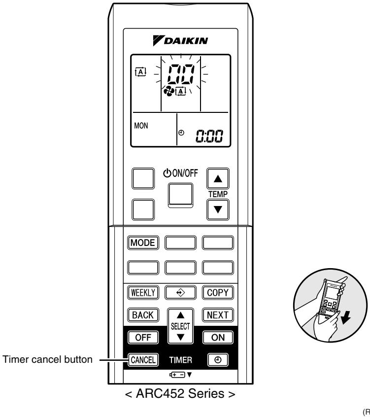
text_image
DAIKIN A 0:00 MON ON/OFF ▲ TEMP MODE WEEKLY COPY BACK SELECT OFF ON CANCEL TIMER Timer cancel button < ARC452 Series > (R)- Press the timer cancel button repeatedly until a long beep sounds.
■ The code indication changes in the sequence shown below.
| No. | Code | No. | Code | No. | Code |
| 1 | 00 | 13 | 07 | 25 | 08 |
| 2 | 04 | 14 | 83 | 26 | 09 |
| 3 | 15 | 15 | 88 | 27 | 94 |
| 4 | 86 | 16 | 89 | 28 | 13 |
| 5 | 86 | 17 | 09 | 29 | 14 |
| 6 | 00 | 18 | 04 | 30 | 07 |
| 7 | 86 | 19 | 05 | 31 | 02 |
| 8 | 87 | 20 | 03 | 32 | 88 |
| 9 | 00 | 21 | 06 | 33 | 89 |
| 10 | F3 | 22 | 85 | 34 | 88 |
| 11 | 85 | 23 | 81 | ||
| 12 | F6 | 24 | 81 |

Note:
- A short beep or 2 consecutive beeps indicate non-corresponding codes.
- To return to the normal mode, hold the timer cancel button down for 5 seconds. When the remote controller is left untouched for 60 seconds, it also returns to the normal mode.
- Not all the error codes are displayed. When you cannot find the error code, try the check method 2. ( Refer to page 258.)
Check Method 2
- Press the 3 buttons ([TEMP] ▲, [TEMP] ▼, [MODE]) at the same time to enter the diagnosis mode.
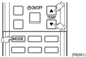
text_image
ON/OFF TEMP MODE (R8381)The left-side number blinks.
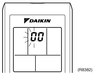
text_image
DAIKIN 00 (R8382)- Press the [TEMP] ▲ or ▼ button and change the number until you hear the two consecutive beeps or the long beep.

text_image
ON/OFF TEMP MODE (R8383)- Diagnose by the sound.
★ beep : The left-side number does not correspond with the error code.
★ two consecutive beeps : The left-side number corresponds with the error code but the right-side number does not.
★ long beep : Both the left-side and right-side numbers correspond with the error code. The numbers indicated when you hear the long beep are the error code. Error codes and description → Refer to page 267.
- Press the [MODE] button.
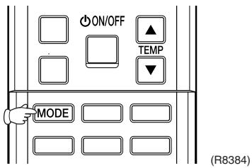
text_image
ON/OFF TEMP MODE (R8384)The right-side number blinks.
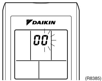
text_image
DAIKIN 00 (R8385)- Press the [TEMP] ▲ or ▼ button and change the number until you hear the long beep.
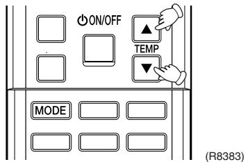
text_image
ON/OFF TEMP MODE (R8383)- Diagnose by the sound.
★ beep : The left-side number does not correspond with the error code.
★ two consecutive beeps : The left-side number corresponds with the error code but the right-side number does not.
★ long beep : Both the left-side and right-side numbers correspond with the error code.
- Determine the error code.
The numbers indicated when you hear the long beep are the error code.
Error codes and description → Refer to page 267.
- Press the [MODE] button to exit from the diagnosis mode.
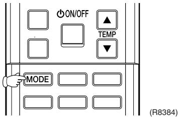
text_image
ON/OFF TEMP MODE (R8384)The display 7 means the trial operation mode.
Refer to page 408 for trial operation.

text_image
DAIKIN 7- (R9659)- Press the [ON/OFF] button twice to return to the normal mode.

text_image
ON/OFF TEMP MODE (R9660)
Note: When the remote controller is left untouched for 60 seconds, it returns to the normal mode.
3.1.3 ARC433 Series Remote Controller
Check Method 1
- When the timer cancel button is held down for 5 seconds, 30 is displayed on the temperature display screen.
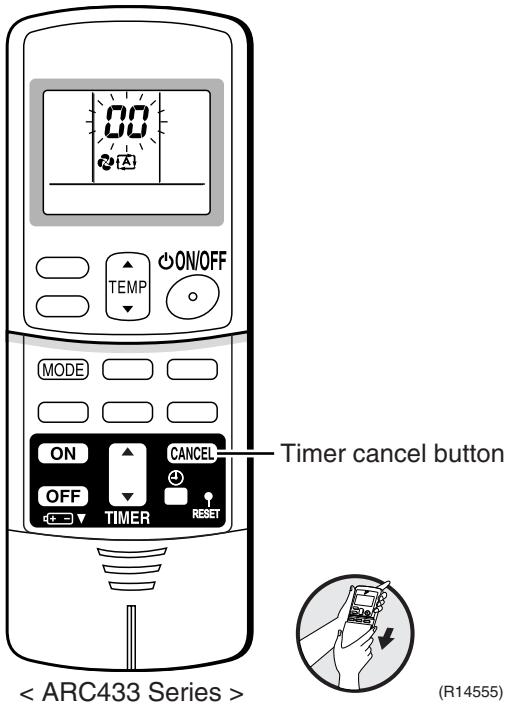
text_image
00 ON/OFF TEMP MODE ON CANCEL OFF TIMER RESET Timer cancel button < ARC433 Series > (R14555)- Press the timer cancel button repeatedly until a long beep sounds.
■ The code indication changes in the sequence shown below.
| No. | Code | No. | Code | No. | Code |
| 1 | 00 | 12 | 07 | 23 | 80 |
| 2 | 04 | 13 | 08 | 24 | 81 |
| 3 | F3 | 14 | 03 | 25 | 94 |
| 4 | E6 | 15 | 83 | 26 | L3 |
| 5 | L5 | 16 | 81 | 27 | L4 |
| 6 | R6 | 17 | C4 | 28 | K6 |
| 7 | E5 | 18 | C5 | 29 | K7 |
| 8 | F6 | 19 | K9 | 30 | U2 |
| 9 | C9 | 20 | J6 | 31 | U4 |
| 10 | 00 | 21 | 08 | 32 | E8 |
| 11 | E7 | 22 | 85 | 33 | 84 |

Note:
- A short beep or two consecutive beeps indicate non-corresponding codes.
- To return to the normal mode, hold the timer cancel button down for 5 seconds. When the remote controller is left untouched for 60 seconds, it also returns to the normal mode.
- Not all the error codes are displayed. When you cannot find the error code, try the check method 2. ( Refer to page 261.)
Check Method 2
- Press the center of the [TEMP] button and the [MODE] button at the same time to enter the diagnosis mode.
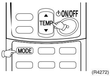
text_image
ON/OFF TEMP MODE (R4272)The left-side number blinks.
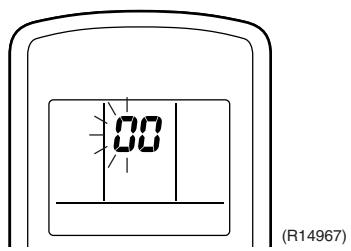
text_image
00 (R14967)- Press the [TEMP] ▲ or ▼ button and change the number until you hear the two consecutive beeps or the long beep.
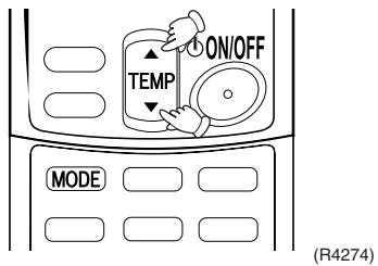
text_image
ON/OFF TEMP MODE (R4274)- Diagnose by the sound.
★ beep : The left-side number does not correspond with the error code.
★ two consecutive beeps : The left-side number corresponds with the error code but the right-side number does not.
★ long beep : Both the left-side and right-side numbers correspond with the error code. The numbers indicated when you hear the long beep are the error code. Error codes and description → Refer to page 267.
- Press the [MODE] button.
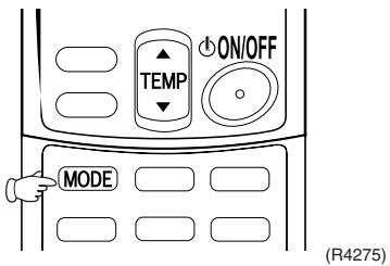
text_image
ON/OFF TEMP MODE (R4275)The right-side number blinks.
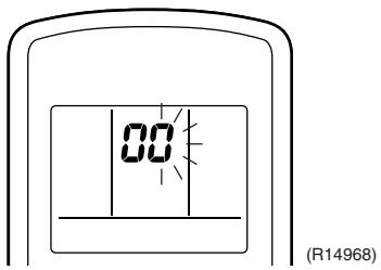
text_image
00 (R14968)- Press the [TEMP] ▲ or ▼ button and change the number until you hear the long beep.
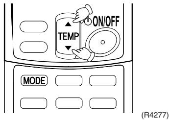
text_image
ON/OFF TEMP MODE (R4277)- Diagnose by the sound.
★ beep : The left-side number does not correspond with the error code.
★ two consecutive beeps : The left-side number corresponds with the error code but the right-side number does not.
★ long beep : Both the left-side and right-side numbers correspond with the error code.
- Determine the error code.
The numbers indicated when you hear the long beep are the error code.
Error codes and description → Refer to page 267.
- Press the [MODE] button to exit from the diagnosis mode.
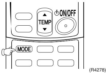
text_image
ON/OFF TEMP MODE (R4278)The display 7 means the trial operation mode. Refer to page 408 for trial operation.
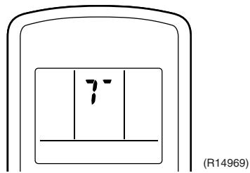
text_image
7 (R14969)- Press the [ON/OFF] button twice to return to the normal mode.
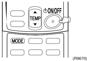
text_image
TEMP ON/OFF MODE (R9670)
Note: When the remote controller is left untouched for 60 seconds, it returns to the normal mode.
3.2 SA Indoor Unit - FCQG, FFQ, FHQ, FDBQ, FBQ Series
3.2.1 Relations between Modes
BRC1D528
The following modes can be selected by using the [Inspection / Test] button on the remote controller.
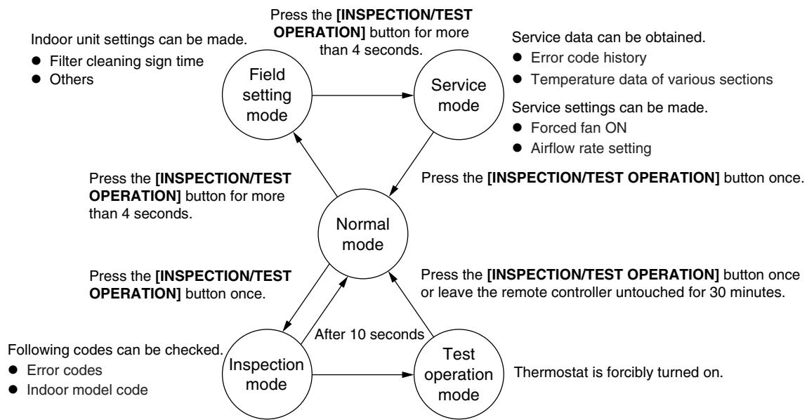
flowchart
graph TD
    A["Field setting mode"] --> B["Service mode"]
    B --> C["Normal mode"]
    C --> D["Inspection mode"]
    D --> E["Test operation mode"]
    E --> C
    style A fill:#f9f,stroke:#333
    style B fill:#f9f,stroke:#333
    style C fill:#ccf,stroke:#333
    style D fill:#ccf,stroke:#333
    style E fill:#ccf,stroke:#333
    note1["Indoor unit settings can be made."]
    note2["Filter cleaning sign time"]
    note3["Others"]
    note4["Press the [INSPECTION/TEST OPERATION"] button for more than 4 seconds.]
    note5["Press the [INSPECTION/TEST OPERATION"] button once.]
    note6["Press the [INSPECTION/TEST OPERATION"] button once or leave the remote controller untouched for 30 minutes.]
    note7["Following codes can be checked."]
    note8["Error codes"]
    note9["Indoor model code"]
    note10["Thermostat is forcibly turned on."]
    note11["Press the [INSPECTION/TEST OPERATION"] button once or leave the remote controller untouched for 30 minutes.]
    note12["Press the [INSPECTION/TEST OPERATION"] button once or leave the remote controller untouched for 30 minutes.]
    note13["Service data can be obtained."]
    note14["Error code history"]
    note15["Temperature data of various sections"]
    note16["Service settings can be made."]
    note17["Forced fan ON"]
    note18["Airflow rate setting"]
Press the [INSPECTION/TEST OPERATION] button once.
(R15367)
BRC1E52A7, BRC1E52B7
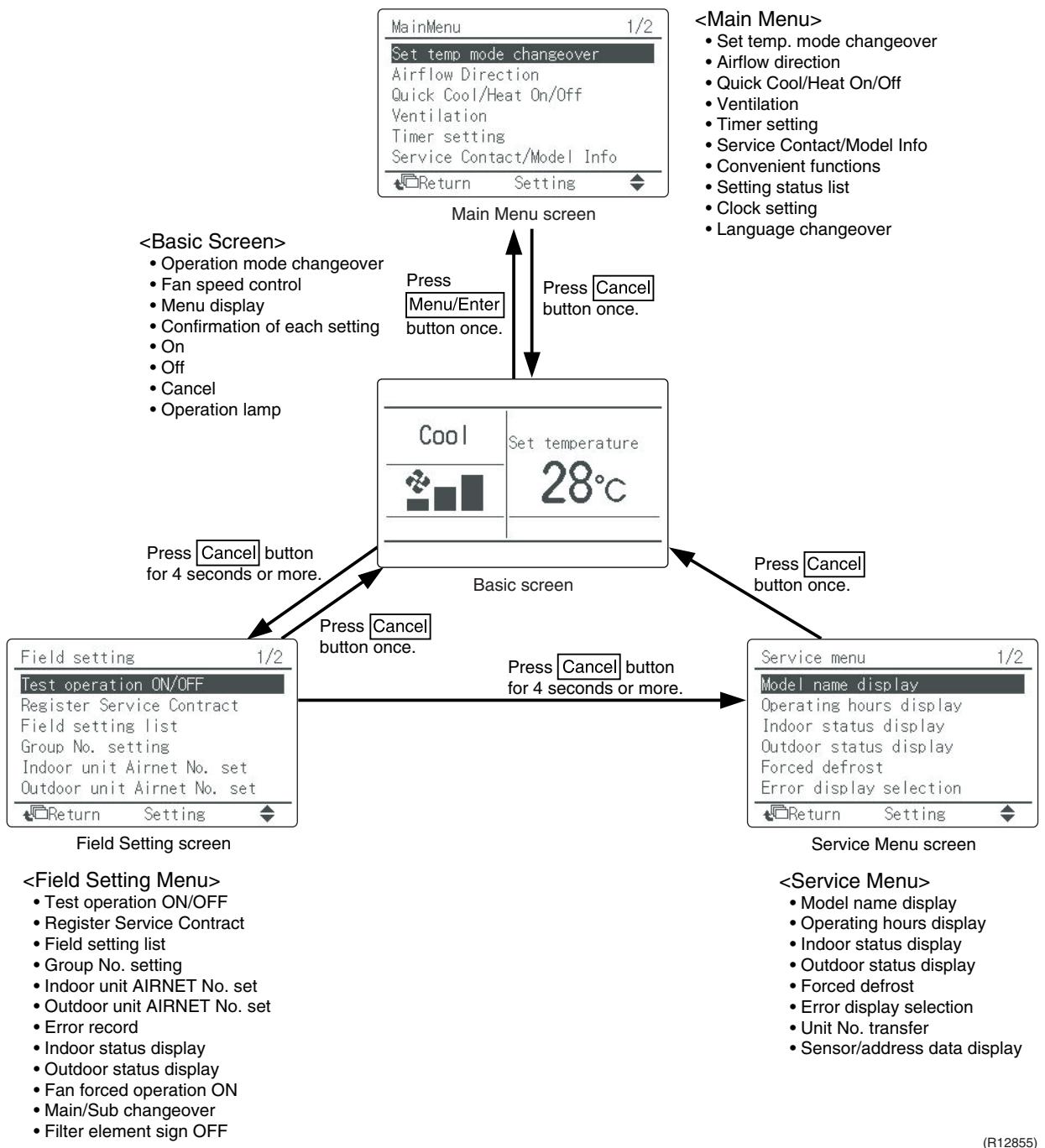
flowchart
graph TD
    A["Field Setting Screen"] --> B["Basic Screen"]
    B --> C["Service Menu Screen"]
    subgraph Field Setting Screen
        D["Field setting 1/2 Test operation ON/OFF"]
        E["Register Service Contract Field setting list Group No. setting Indoor unit Airnet No. set Outdoor unit Airnet No. set Return Setting"]
    end
    subgraph Service Menu Screen
        F["Model name display Operating hours display Indoor status display Outdoor status display Forced defrost Error display selection Return Setting"]
    end
    G["Main Menu 1/2 Set temp. mode changeover Airflow direction Quick Cool/Heat On/Off Ventilation Timer setting Service Contact/Model Info Convenient functions Setting status list Clock setting Language changeover"] --> H[Press Cancel button once. Press Menu/Enter button once. Press Cancel button once. Press Cancel button for 4 seconds or more. Press Cancel button once. Press Cancel button for 4 seconds or more. Press Cancel button once. Press Cancel button once. Press Cancel button once. Press Cancel button once. Press Cancel button once. Press Cancel button once. Press Cancel button once. Press Cancel button once. Press Cancel button once. Press Cancel button once. Press Cancel button once. Press Cancel button once. Press Cancel button once. Press Cancel button once. Press Cancel button once. Press Cancel button once. Press Cancel button once. Press Cancel button once. Press Cancel button once. Press Cancel button once. Press Cancel button on the main screen
    end
3.2.2 BRC1D528
If operation stops due to malfunction, the operation lamp on the remote controller blinks, and error code is displayed. (Even if stop operation is carried out, malfunction contents are displayed when inspection mode is entered.) The error code enables you to tell what kind of malfunction caused operation to stop.
Refer to page 267 for error code and malfunction contents.
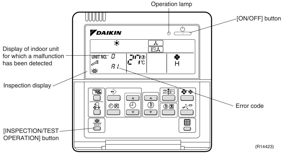
text_image
Operation lamp [ON/OFF] button DAIKIN Display of indoor unit for which a malfunction has been detected UNIT NO. 0 27°C H Inspection display Error code [INSPECTION/TEST OPERATION] button (R14423)
Note:
- When you press the [INSPECTION/TEST OPERATION] button, the inspection display blinks.
- While in the inspection mode, press the [ON/OFF] button for 5 seconds or more to clear the failure history indication. In this case, the error code blinks twice and then changes to (= Normal), the UNIT No. changes to , and the operation mode automatically switches from the inspection mode to the normal mode (displaying the set temperature).
3.2.3 BRC1E52A7, BRC1E52B7
The following display appears on the screen when a error (or a warning) occurs during operation.
Check the error code and take the corrective action specified for the particular model.
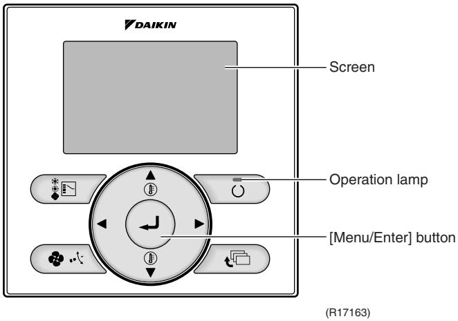
text_image
DAIKIN Screen Operation lamp [Menu/Enter] button (R17163)(1) Check if it is error or warning.
| Operation status | Display | ||
| Abnormal shutdown | The system stops operating. | The operation lamp (green) starts to blink. The message "Error: Press Menu Button" appears and blinks at the bottom of the screen. | 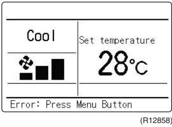 |
| Warning | The system continues its operation. | The operation lamp (green) remains on. The message "Warning: Press Menu Button" appears and blinks at the bottom of the screen. | 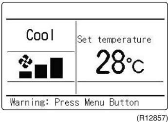 |
(2) Take corrective action.
- Press the [Menu/Enter] button to check the error code.

· Take the corrective action specific to the model.
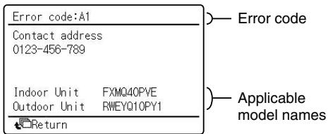
text_image
Error code:A1 Contact address 0123-456-789 Indoor Unit FXMQ40PVE Outdoor Unit RWEYQ10PY1 Return Error code Applicable model names(R12859)
4. Code Indication on Remote Controller
4.1 RA Indoor Unit - FTXG, FTXS, CTXS, FVXG, FVXS, FLXS, FDXS Series
| Error Codes | Description | Reference Page | |
| 00 | Normal condition | — | |
| R1 | Indoor unit PCB abnormality | 270 | |
| R5 | Freeze-up protection control or heating peak-cut control | 272 | |
| R6 | Fan motor or related abnormality | DC motor (wall, floor standing) | 274 |
| AC motor (floor / ceiling, duct) | 277 | ||
| R9 | Radiant panel temperature rise, indoor electronic expansion valve (motor operated valve) abnormality, freeze-up protection control (FVXG series only) | 278 | |
| C4 | Indoor heat exchanger thermistor or related abnormality | 280 | |
| C7 | Front panel open / close fault (FTXG series only) | 281 | |
| C9 | Room temperature thermistor or related abnormality | 280 | |
| CE | Radiant panel thermistor or related abnormality (FVXG series only) | 280 | |
| U4 | Signal transmission error (between indoor unit and outdoor unit) | 282 | |
| U8 | Unspecified voltage (between indoor unit and outdoor unit) | 283 | |
4.2 SA Indoor Unit - FCQG, FFQ, FHQ, FDBQ, FBQ Series
| Error Codes | Description | Reference Page |
| 00 | Normal condition | — |
| R1 | Indoor unit PCB abnormality | 284 |
| R3 | Drain water level system abnormality | 285 |
| R6 | Fan motor or related abnormality | 287 |
| R7 | Swing motor lock (FHQ series only) | 289 |
| R9 | Drain system abnormality | 290 |
| C4 | Indoor heat exchanger thermistor or related abnormality | 291 |
| C9 | Room temperature thermistor or related abnormality | 291 |
| CJ | Remote controller thermistor abnormality | 292 |
| US | Signal transmission error (between indoor unit and remote controller) | 293 |
| US | Signal transmission error (between MAIN remote controller and SUB remote controller) | 294 |
| UR | Field setting abnormality | 295 |
: Error code displays automatically and system stops.
Inspect and solve the error.
: In the case of the shaded error codes, "inspection" is not displayed. The system
operates, but be sure to inspect and solve the error.
4.3 Sub Codes for SA Indoor Unit
If an error code like the one shown below is displayed when the navigation remote controller (BRC1E52A7, BRC1E52B7) is in use, make a detailed diagnosis or a diagnosis of the relevant unit referring to the attached list.
| Error codes | Description | Troubleshooting |
| A6 - 01 | Fan motor locked | A locked fan motor current has been detected.Turn the fan by hand to check for the connection of connectors. |
| A6 - 10 | Fan overcurrent error | A fan motor overcurrent has been detected.Check for the connection of the connector between the fan motor and the PCB. If the connection is normal, replace the fan motor. If this still cannot solve the error, replace the PCB. |
| A6 - 11 | Fan position detection error | An error in the detection of position of the fan motor. Check for the connection of the connector between the fan motor and the PCB. If the connection is normal, replace the fan motor. If this still cannot solve the error, replace the PCB. |
| AH - 03 | Transmission error (between the self-cleaning decoration panel and the indoor unit)[when the self-cleaning decoration panel is mounted] | Check for the connection of the harness connector between the panel PCB and the indoor unit PCB. |
| AH - 04 | Dust detection sensor error[when the self-cleaning decoration panel is mounted] | Check for the connections of the connector X12A on the panel PCB and the connectors X18A and X19A on the sensor PCBs. |
| AH - 05 | Dust collection sign error[when the self-cleaning decoration panel is mounted] | Check for clogging with dust at the dust collection port as well as in the brush unit, S-shaped pipe, and dust box.Furthermore, check for any stains of the light receiving and emitting parts of the infrared unit. |
| AH - 06 | Air filter rotation error[when the self-cleaning decoration panel is mounted] | Check for anything getting in the way of rotating the filter (e.g. the filter comes off or the drive gear is clogged with foreign matters). |
| AH - 07 | Damper rotation error[when the self-cleaning decoration panel is mounted] | The damper does not rotate normally. Check for any foreign matters around the damper and for the operation of the gear and limit switch. |
| AH - 08 | Filter self-cleaning operation error[when the self-cleaning decoration panel is mounted] | The unit has not yet completed the filter self-cleaning operation even after the lapse of specified period of time. Check for any external noise, etc. |
| AH - 09 | Filter self-cleaning operation start disabled error[when the self-cleaning decoration panel is mounted] | The unit has been put into a state in which the filter self-cleaning operation is disabled. Check the unit for the operating conditions. |
| C6 - 01 | Faulty combination of indoor unit PCB and fan PCB | A combination of indoor unit PCB and fan PCB is defective. Check whether the capacity setting adaptor is correct and the type of the fan PCB is correct. |
4.4 Outdoor Unit
☀: ON, ●: OFF, ⏻: Blinks
Green : Blinks in normal condition
Red : OFF in normal condition
| Outdoor Unit LED Indication | Error Codes | Description | Reference Page | |||||
| Green | Red | |||||||
| A | 1 | 2 | 3 | 4 | 5★ | |||
| ● | ● | ● | ● | ● | 00 | Normal condition | — | |
| U9 | Unspecified voltage (between indoor unit and outdoor unit) | 301 | ||||||
| UH | Anti-icing function in other rooms | 301 | ||||||
| ● | ● | ○ | ○ | ● | (UO) | Refrigerant shortage | 296 | |
| ○ | ● | ● | ○ | ● | U2 | Low-voltage detection or over-voltage detection | 298 | |
| ● | ○ | ○ | ○ | ● | U7 | Signal transmission error (on outdoor unit PCB) | 300 | |
| ○ | ● | ○ | ○ | ● | AS | Anti-icing function | 302 | |
| ○ | ○ | ○ | ● | ● | E1 | Outdoor unit PCB abnormality | 304 | |
| ○ | ● | ○ | ● | ● | (ES) | OL activation (compressor overload) | 305 | |
| ● | ○ | ○ | ● | ● | (ES) | Compressor lock | 306 | |
| ○ | ○ | ○ | ○ | ● | E7 | DC fan lock | 307 | |
| ● | ○ | ● | ○ | ● | E8 | Input overcurrent detection | 308 | |
| ○ | ● | ○ | ● | ● | F3 | Discharge pipe temperature control | 309 | |
| ○ | ● | ○ | ○ | ● | F6 | High pressure control in cooling | 310 | |
| ○ | ○ | ● | ● | ● | HO | Compressor sensor system abnormality | 311 | |
| HO | Position sensor abnormality | 313 | ||||||
| HO | CT or related abnormality | 315 | ||||||
| HO | Outdoor temperature thermistor or related abnormality | 317 | ||||||
| U3 | Discharge pipe thermistor or related abnormality | 317 | ||||||
| U6 | Outdoor heat exchanger thermistor or related abnormality | 317 | ||||||
| U8 | Liquid pipe thermistor or related abnormality | 317 | ||||||
| U9 | Gas pipe thermistor or related abnormality | 317 | ||||||
| P4 | Radiation fin thermistor or related abnormality | 317 | ||||||
| ○ | ○ | ● | ○ | ● | L3 | Electrical box temperature rise | 319 | |
| ● | ● | ● | ○ | ● | L4 | Radiation fin temperature rise | 321 | |
| ● | ● | ○ | ● | ● | L5 | Output overcurrent detection | 323 | |

Note:
- The error codes in the parenthesis ( ) are displayed only when the system is shut down.
- When a sensor error occurs, check the remote controller display to determine which sensor is malfunctioning.
If the remote controller does not indicate the error code, conduct the following procedure.
* Turn the power switch off and back on again. If the same LED indication appears again immediately after the power is turned on, the fault is in the thermistor.
* If the above condition does not result, the fault is in the CT.
-
The indoor unit error code may take the precedence in the remote controller display.
-
★ 3-room models and 4-room models do not have LED5.
5. Troubleshooting for RA Indoor Unit - FTXG, FTXS, CTXS, FVXG, FVXS, FLXS, FDXS Series
5.1 Indoor Unit PCB Abnormality
| Remote Controller Display | R1 |
| Method of Malfunction Detection | The system checks if the circuit works properly within the microcomputer of the indoor unit. |
| Malfunction Decision Conditions | The system cannot set the internal settings. |
| Supposed Causes | ■ Wrong models interconnected■ Defective indoor unit PCB■ Disconnection of connector■ Reduction of power supply voltage |
Troubleshooting
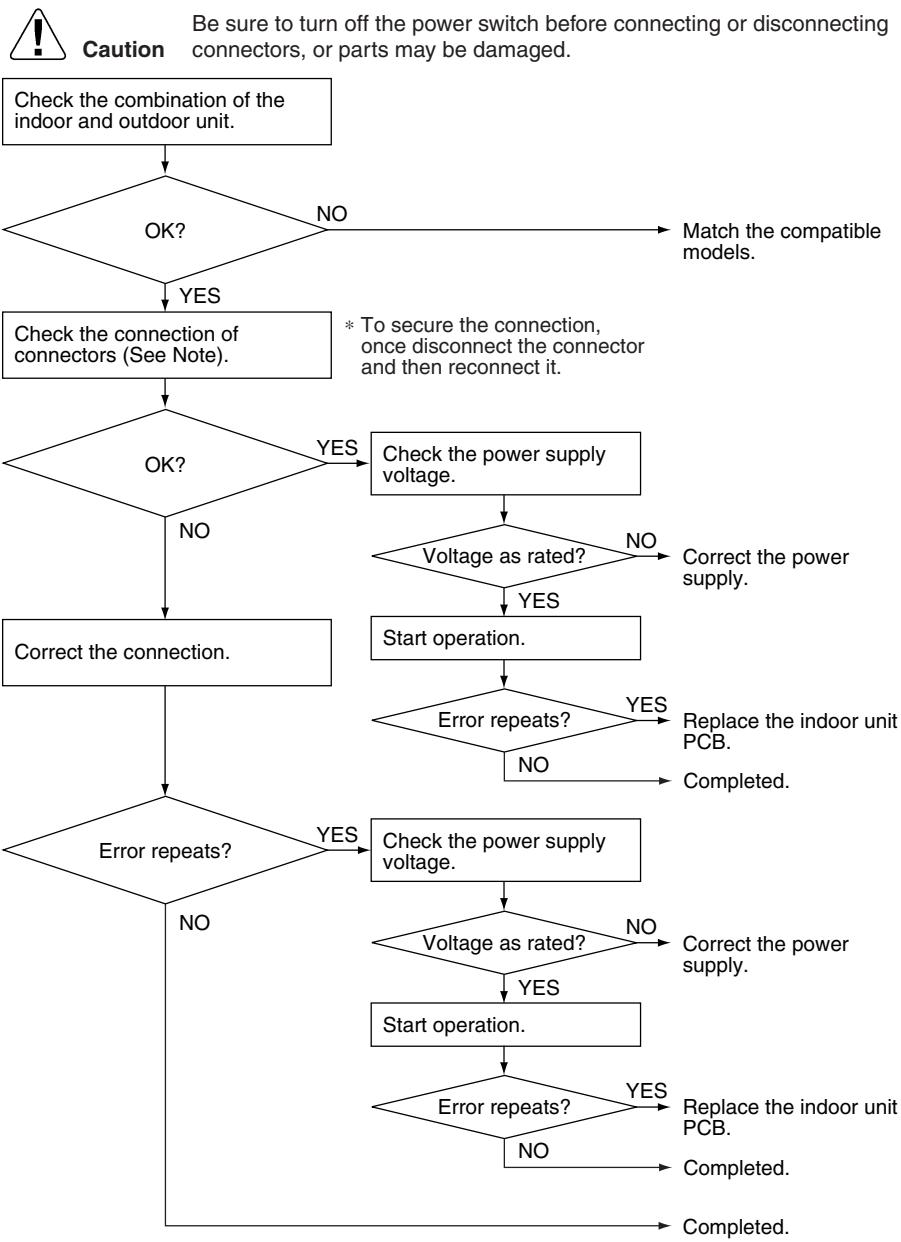
flowchart
graph TD
    A["Check the combination of the indoor and outdoor unit."] --> B{OK?}
    B -->|NO| C["Match the compatible models."]
    B -->|YES| D["Check the connection of connectors (See Note)."]
    D --> E{OK?}
    E -->|NO| F["Correct the connection."]
    E -->|YES| G["Check the power supply voltage."]
    G --> H{Voltage as rated?}
    H -->|NO| I["Correct the power supply."]
    H -->|YES| J["Start operation."]
    J --> K{Error repeats?}
    K -->|NO| L["Replace the indoor unit PCB."]
    K -->|YES| M["Completed."]
    K -->|YES| N["Check the power supply voltage."]
    N --> O{Voltage as rated?}
    O -->|NO| P["Correct the power supply."]
    O -->|YES| Q["Start operation."]
    Q --> R{Error repeats?}
    R -->|NO| S["Replace the indoor unit PCB."]
    R -->|YES| T["Completed."]
    R -->|YES| U["Completed."]
    R -->|YES| V["Completed."]
    N --> W["No"]
    O --> X["No"]
    style A fill:#f9f,stroke:#333
    style V fill:#f9f,stroke:#333
(R15310)

Note: Check the following connector.
| Model Type | Connector |
| Wall mounted type | Terminal board ~ Control PCB |
| Floor standing type | Terminal board ~ Control PCB |
| Floor / ceiling suspended dual type | S36 ~ S37 |
| Duct connected type | Terminal board ~ Control PCB |
5.2 Freeze-up Protection Control or Heating Peak-cut Control
| Remote Controller Display | RS |
| Method of Malfunction Detection | ■ Freeze-up protection controlDuring cooling operation, the freeze-up protection control (operation halt) is activated according to the temperature detected by the indoor heat exchanger thermistor.■ Heating peak-cut controlDuring heating operation, the temperature detected by the indoor heat exchanger thermistor is used for the heating peak-cut control (operation halt, outdoor fan stop, etc.) |
| Malfunction Decision Conditions | ■ Freeze-up protection controlDuring cooling operation, the indoor heat exchanger temperature is below 0°C.■ Heating peak-cut controlDuring heating operation, the indoor heat exchanger temperature is above 65°C. |
| Supposed Causes | ■ Short-circuited air■ Clogged air filter of the indoor unit■ Dust accumulation on the indoor heat exchanger■ Defective indoor heat exchanger thermistor■ Defective indoor unit PCB |
Troubleshooting

Check No.01
Refer to P.325

Caution
Be sure to turn off the power switch before connecting or disconnecting connectors, or parts may be damaged.
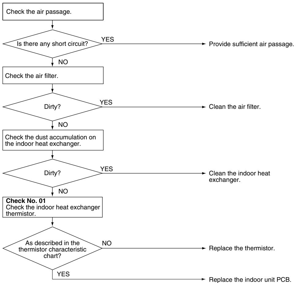
flowchart
graph TD
    A["Check the air passage."] --> B{Is there any short circuit?}
    B -->|YES| C["Provide sufficient air passage."]
    B -->|NO| D["Check the air filter."]
    D --> E{Dirty?}
    E -->|YES| F["Clean the air filter."]
    E -->|NO| G["Check the dust accumulation on the indoor heat exchanger."]
    G --> H{Dirty?}
    H -->|YES| I["Clean the indoor heat exchanger."]
    H -->|NO| J["Check No. 01 Check the indoor heat exchanger thermistor."]
    J --> K{As described in the thermistor characteristic chart?}
    K -->|NO| L["Replace the thermistor."]
    K -->|YES| M["Replace the indoor unit PCB."]
(R15715)
5.3 Fan Motor or Related Abnormality
5.3.1 DC Motor (Wall Mounted Type, Floor Standing Type)
| Remote Controller Display | 86 |
| Method of Malfunction Detection | The rotation speed detected by the Hall IC during fan motor operation is used to determine abnormal fan motor operation. |
| Malfunction Decision Conditions | The detected rotation speed does not reach the demanded rotation speed of the target tap, and is less than 50% of the maximum fan motor rotation speed. |
| Supposed Causes | ■ Disconnection of connector■ Foreign matters stuck in the fan■ Layer short inside the fan motor winding■ Breaking of wire inside the fan motor■ Breaking of the fan motor lead wires■ Defective capacitor of the fan motor■ Defective indoor unit PCB |
Troubleshooting

Check No.02
Refer to P.326
FTXG, FTXS-J, FTXS-G, FVXG, FVXS Series

Caution
Be sure to turn off the power switch before connecting or disconnecting connectors, or parts may be damaged.
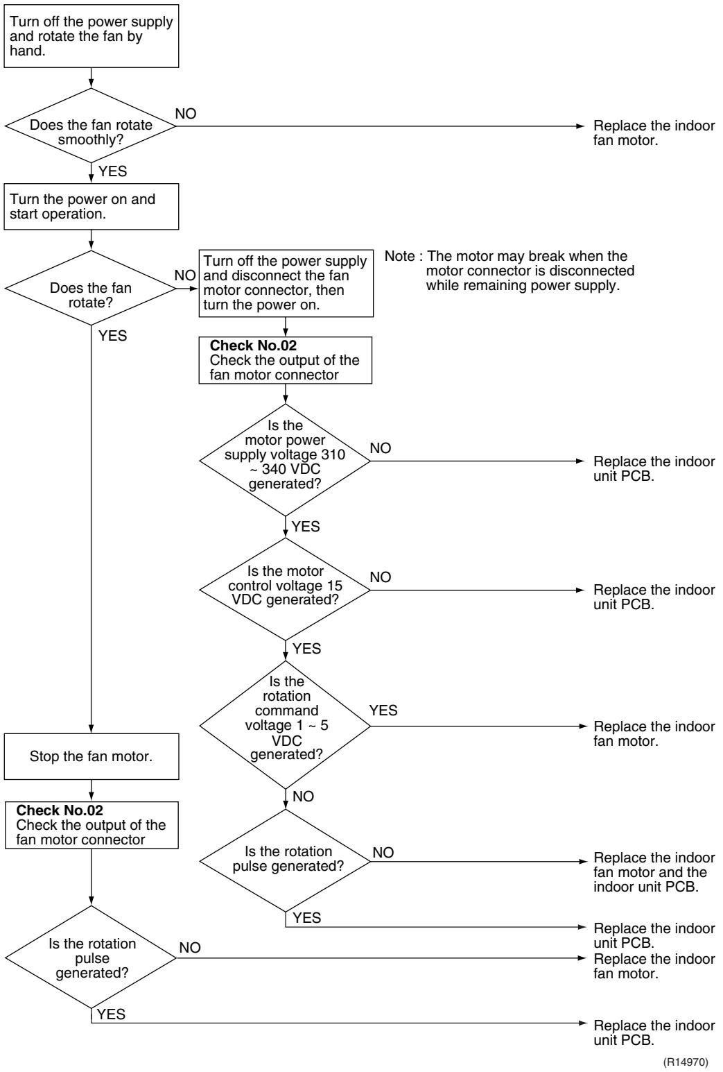
flowchart
graph TD
    A["Turn off the power supply and rotate the fan by hand."] --> B{Does the fan rotate smoothly?}
    B -->|NO| C["Replace the indoor fan motor."]
    B -->|YES| D["Turn the power on and start operation."]
    D --> E{Does the fan rotate?}
    E -->|NO| F["Turn off the power supply and disconnect the fan motor connector, then turn the power on."]
    F --> G["Check No.02<br>Check the output of the fan motor connector"]
    G --> H{Is the motor power supply voltage 310 ~ 340 VDC generated?}
    H -->|NO| I["Replace the indoor unit PCB."]
    H -->|YES| J{Is the motor control voltage 15 VDC generated?}
    J -->|NO| K["Replace the indoor unit PCB."]
    J -->|YES| L{Is the rotation command voltage 1 ~ 5 VDC generated?}
    L -->|YES| M["Replace the indoor fan motor."]
    L -->|NO| N{Is the rotation pulse generated?}
    N -->|NO| O["Replace the indoor fan motor and the indoor unit PCB."]
    N -->|YES| P["Replace the indoor unit PCB."]
    P --> Q["Stop the fan motor."]
    Q --> R["Check No.02<br>Check the output of the fan motor connector"]
    R --> S{Is the rotation pulse generated?}
    S -->|NO| T["Replace the indoor unit PCB."]
    S -->|YES| U["Replace the indoor unit PCB."]
    U --> V["(R14970)"]
Troubleshooting

Check No.03
Refer to P.326
FTXS-K, CTXS-K Series

Caution
Be sure to turn off the power switch before connecting or disconnecting connectors, or parts may be damaged.
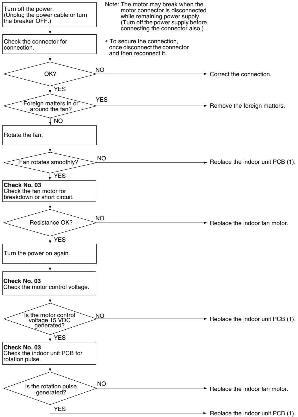
flowchart
graph TD
    A["Turn off the power.<br>(Unplug the power cable or turn<br>the breaker OFF.)"] --> B["Check the connector for connection."]
    B --> C{OK?}
    C -->|NO| D["Correct the connection."]
    C -->|YES| E{Foreign matters in or around the fan?}
    E -->|YES| F["Remove the foreign matters."]
    E -->|NO| G["Rotate the fan."]
    G --> H{Fan rotates smoothly?}
    H -->|NO| I["Replace the indoor unit PCB (1)."]
    H -->|YES| J["Check No. 03<br>Check the fan motor for breakdown or short circuit."]
    J --> K{Resistance OK?}
    K -->|NO| L["Replace the indoor fan motor."]
    K -->|YES| M["Turn the power on again."]
    M --> N["Check No. 03<br>Check the motor control voltage."]
    N --> O{Is the motor control voltage 15 VDC generated?}
    O -->|NO| P["Replace the indoor unit PCB (1)."]
    O -->|YES| Q["Check No. 03<br>Check the indoor unit PCB for rotation pulse."]
    Q --> R{Is the rotation pulse generated?}
    R -->|NO| S["Replace the indoor fan motor."]
    R -->|YES| T["Replace the indoor unit PCB (1)."]
(R16048)
5.3.2 AC Motor (Duct Connected Type, Floor / Ceiling Suspended Dual Type)
| Remote Controller Display | RIS |
| Method of Malfunction Detection | The rotation speed detected by the Hall IC during fan motor operation is used to determine abnormal fan motor operation. |
| Malfunction Decision Conditions | The detected rotation speed does not reach the demanded rotation speed of the target tap, and is less than 50% of the maximum fan motor rotation speed. |
| Supposed Causes | ■ Layer short inside the fan motor winding■ Breaking of wire inside the fan motor■ Breaking of the fan motor lead wires■ Defective capacitor of the fan motor■ Defective indoor unit PCB |
Troubleshooting

Check No.04
Refer to P.327

Caution
Be sure to turn off the power switch before connecting or disconnecting connectors, or parts may be damaged.
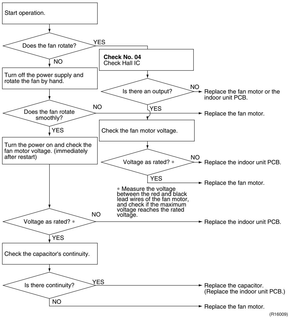
flowchart
graph TD
    A["Start operation."] --> B{Does the fan rotate?}
    B -->|NO| C["Turn off the power supply and rotate the fan by hand."]
    B -->|YES| D["Check No. 04 Check Hall IC"]
    C --> E{Does the fan rotate smoothly?}
    E -->|NO| F["Check the fan motor voltage."]
    E -->|YES| G["Turn the power on and check the fan motor voltage. (immediately after restart)"]
    E -->|YES| H{Voltage as rated? *}
    H -->|NO| I["Check the capacitor's continuity."]
    H -->|YES| J["Voltage as rated? *"]
    J --> K{Is there continuity?}
    K -->|NO| L["End"]
    K -->|YES| M["Replace the capacitor. (Replace the indoor unit PCB.)"]
    L --> N["Replace the fan motor."]
    M --> O["Replace the indoor unit PCB."]
    N --> P["Replace the fan motor."]
    O --> Q["Replace the fan motor."]
    P --> R["Replace the fan motor."]
    Q --> S["Replace the fan motor."]
    R --> T["Replace the fan motor."]
5.4 Radiant Panel Temperature Rise, Indoor Electronic Expansion Valve (Motor Operated Valve) Abnormality, Freeze-up Protection Control (FVXG Series Only)
| Remote Controller Display | 89 |
| Method of Malfunction Detection | Radiant panel temperature riseDuring RADIANT operation, high temperature control (e.g., operation halt, indoor electronic expansion valve closure) is activated according to the temperature detected by the radiant panel thermistors.Indoor electronic expansion valve abnormalityThe indoor electronic expansion valve is required to be fully closed during cooling, dry or heating operation. When the indoor electronic expansion valve is open due to malfunction, the refrigerant flows into the radiant panel and the radiant panel temperature rises or drops.The indoor electronic expansion valve is required to be open during RADIANT operation.When the indoor electronic expansion valve is closed due to malfunction, the refrigerant does not flow into the radiant panel and the radiant panel temperature does not rise.For multi systemThe indoor electronic expansion valve is required to be fully closed in the room where the system does not run. When the indoor electronic expansion valve is open due to malfunction and heating or RADIANT operation is conducted in the other room(s), the refrigerant flows into the radiant panel and the radiant panel temperature rises.Freeze-up protection controlThe temperature detected by the radiant panel thermistors is used to prevent the indoor unit from freezing during cooling operation. |
| Malfunction Decision Conditions | Radiant panel temperature riseThe radiant panel surface temperature calculated by the radiant panel thermistors is above 70°C.Indoor electronic expansion valve abnormalityDuring cooling or dry operation, the temperature detected by the radiant panel thermistor ( 4) has dropped.During heating operation, the temperature detected by the radiant panel thermistor ( 4) has risen.During RADIANT operation, the temperature detected by the radiant panel thermistor ( 4) does not rise.For multi systemWhile the system does not run and heating or RADIANT operation is conducted in the other room(s), the temperature detected by the radiant panel thermistor ( 4) has risen.Freeze-up protection controlDuring cooling operation, the operation stops when the temperature detected by the radiant panel thermistor ( 4) has dropped. |
| Supposed Causes | Clogged air filter of the indoor unitDust accumulation on the indoor heat exchangerShort-circuited airDefective radiant panel thermistor(s)Defective indoor heat exchanger thermistorDefective room temperature thermistorDefective indoor electronic expansion valve (or coil) |
Troubleshooting

Check No.01
Refer to P.325

Check No.06
Refer to P.327

Caution
Be sure to turn off the power switch before connecting or disconnecting connectors, or parts may be damaged.
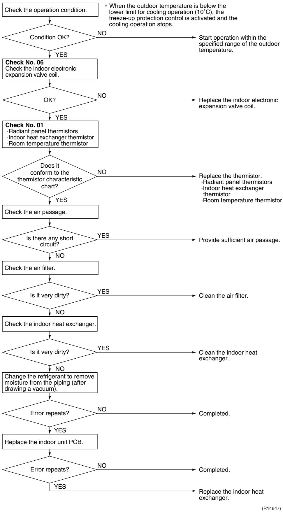
flowchart
graph TD
    A["Check the operation condition."] --> B{Condition OK?}
    B -->|NO| C["Start operation within the specified range of the outdoor temperature."]
    B -->|YES| D["Check No. 06<br>Check the indoor electronic expansion valve coil."]
    D --> E{OK?}
    E -->|NO| F["Replace the indoor electronic expansion valve coil."]
    E -->|YES| G["Check No. 01<br>·Radiant panel thermistors<br>·Indoor heat exchanger thermistor<br>·Room temperature thermistor"]
    G --> H{Does it conform to the thermistor characteristic chart?}
    H -->|NO| I["Replace the thermistor.<br>·Radiant panel thermistors<br>·Indoor heat exchanger thermistor<br>·Room temperature thermistor"]
    H -->|YES| J["Check the air passage."]
    J --> K{Is there any short circuit?}
    K -->|YES| L["Provide sufficient air passage."]
    K -->|NO| M["Check the air filter."]
    M --> N{Is it very dirty?}
    N -->|YES| O["Clean the air filter."]
    N -->|NO| P["Check the indoor heat exchanger."]
    P --> Q{Is it very dirty?}
    Q -->|YES| R["Clean the indoor heat exchanger."]
    Q -->|NO| S["Change the refrigerant to remove moisture from the piping (after drawing a vacuum)."]
    S --> T{Error repeats?}
    T -->|NO| U["Completed."]
    T -->|YES| V["Replace the indoor unit PCB."]
    V --> W{Error repeats?}
    W -->|NO| X["Completed."]
    W -->|YES| Y["Replace the indoor heat exchanger."]
5.5 Thermistor or Related Abnormality (RA Indoor Unit)
| Remote Controller Display | C4, C9, CE |
| Method of Malfunction Detection | The temperatures detected by the thermistors are used to determine thermistor errors. |
| Malfunction Decision Conditions | The thermistor input is more than 4.96 V or less than 0.04 V during compressor operation. |
| Supposed Causes | ■ Disconnection of connector■ Defective thermistor■ Defective indoor unit PCB |
Troubleshooting

Check No.01
Refer to P.325

Caution
Be sure to turn off the power switch before connecting or disconnecting connectors, or parts may be damaged.
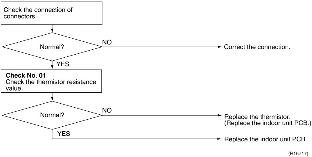
flowchart
graph TD
    A["Check the connection of connectors."] --> B{Normal?}
    B -->|NO| C["Correct the connection."]
    B -->|YES| D["Check No. 01\nCheck the thermistor resistance value."]
    D --> E{Normal?}
    E -->|NO| F["Replace the thermistor.\n(Replace the indoor unit PCB.)"]
    E -->|YES| G["Replace the indoor unit PCB."]
C4: Indoor heat exchanger thermistor
C9 : Room temperature thermistor
CE : Radiant panel thermistor (FVXG series only)
5.6 Front Panel Open / Close Fault (FTXG Series Only)
| Remote Controller Display | [1] |
| Method of Malfunction Detection | |
| Malfunction Decision Conditions | ■ If the error repeats, the system is shut down. |
| Supposed Causes | ■ Defective reduction motor■ Malfunction or deterioration of the front panel mechanism■ Defective limit switch |
Troubleshooting
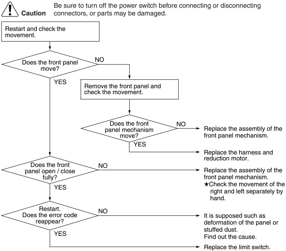
flowchart
graph TD
    A["Restart and check the movement."] --> B{Does the front panel move?}
    B -->|NO| C["Remove the front panel and check the movement."]
    B -->|YES| D{Does the front panel open / close fully?}
    C --> E{Does the front panel mechanism move?}
    E -->|NO| F["Replace the assembly of the front panel mechanism."]
    E -->|YES| G["Replace the harness and reduction motor."]
    D -->|NO| H{Does the front panel open / close fully?}
    H -->|YES| I{Restart. Does the error code reappear?}
    H -->|NO| J["Replace the assembly of the front panel mechanism. ★Check the movement of the right and left separately by hand."]
    I -->|YES| K["Replace the limit switch."]
    I -->|NO| L["It is supposed such as deformation of the panel or stuffed dust. Find out the cause."]
(R17249)

Note: You cannot operate the unit by the remote controller when the front panel mechanism breaks down.
-
Turn off the power.
-
Remove the front panel.
-
Turn on the power.
(Wait until the initialization finishes.)
- Operate the unit by the indoor unit [ON/OFF] button.
5.7 Signal Transmission Error (between Indoor Unit and Outdoor Unit)
| Remote Controller Display | 14 |
| Method of Malfunction Detection | The data received from the outdoor unit in indoor unit-outdoor unit signal transmission is checked whether it is normal. |
| Malfunction Decision Conditions | The data sent from the outdoor unit cannot be received normally, or the content of the data is abnormal. |
| Supposed Causes | ■ Wiring error■ Breaking of the connection wires between the indoor and outdoor units (wire No. 3)■ Defective outdoor unit PCB■ Defective indoor unit PCB■ Disturbed power supply waveform |
Troubleshooting

Check No.11
Refer to P.328
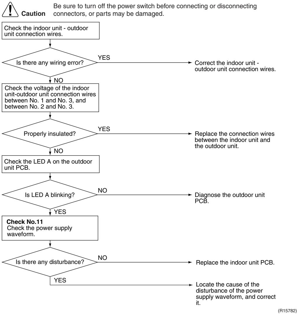
flowchart
graph TD
    A["Check the indoor unit - outdoor unit connection wires."] --> B{Is there any wiring error?}
    B -->|YES| C["Correct the indoor unit - outdoor unit connection wires."]
    B -->|NO| D["Check the voltage of the indoor unit-outdoor unit connection wires between No. 1 and No. 3, and between No. 2 and No. 3."]
    D --> E{Properly insulated?}
    E -->|YES| F["Replace the connection wires between the indoor unit and the outdoor unit."]
    E -->|NO| G["Check the LED A on the outdoor unit PCB."]
    G --> H{Is LED A blinking?}
    H -->|NO| I["Diagnose the outdoor unit PCB."]
    H -->|YES| J["Check No.11 Check the power supply waveform."]
    J --> K{Is there any disturbance?}
    K -->|NO| L["Replace the indoor unit PCB."]
    K -->|YES| M["Locate the cause of the disturbance of the power supply waveform, and correct it."]
5.8 Unspecified Voltage (between Indoor Unit and Outdoor Unit)
| Remote Controller Display | U19 |
| Method of Malfunction Detection | The supply power is detected for its requirements (different from pair type and multi type) by the indoor / outdoor transmission signal. |
| Malfunction Decision Conditions | The pair type and multi type are interconnected. |
| Supposed Causes | ■ Wrong models interconnected■ Wrong wiring of connecting wires■ Wrong indoor unit PCB or outdoor unit PCB mounted■ Defective indoor unit PCB■ Defective outdoor unit PCB |
Troubleshooting
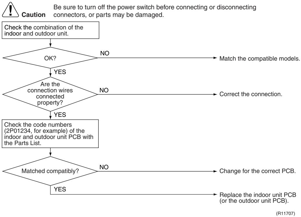
flowchart
graph TD
    A["Check the combination of the indoor and outdoor unit."] --> B{OK?}
    B -->|NO| C["Match the compatible models."]
    B -->|YES| D{Are the connection wires connected property?}
    D -->|NO| E["Correct the connection."]
    D -->|YES| F["Check the code numbers (2P01234, for example) of the indoor and outdoor unit PCB with the Parts List."]
    F --> G{Matched compatibly?}
    G -->|NO| H["Change for the correct PCB."]
    G -->|YES| I["Replace the indoor unit PCB (or the outdoor unit PCB)."]
6. Troubleshooting for SA Indoor Unit - FCQG, FFQ, FHQ, FDBQ, FBQ Series
6.1 Indoor Unit PCB Abnormality
| Remote Controller Display | R1 |
| Method of Malfunction Detection | The system checks the data from EEPROM. |
| Malfunction Decision Conditions | When the data from the EEPROM is not received correctlyEEPROM (Electrically Erasable Programmable Read Only Memory): A memory chip that holds its content without power. It can be erased, either within the computer or externally and usually requires more voltage for erasure than the common +5 volts used in logic circuits. It functions like non-volatile RAM, but writing to EEPROM is slower than writing to RAM. |
| Supposed Causes | ■ Defective indoor unit PCB |
Troubleshooting
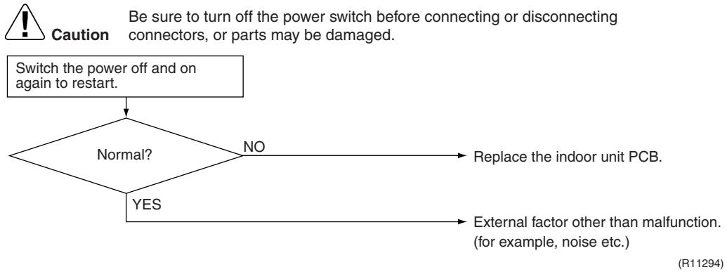
flowchart
graph TD
    A["Switch the power off and on again to restart."] --> B{Normal?}
    B -->|YES| C["Replace the indoor unit PCB."]
    B -->|NO| D["Replace the indoor unit PCB."]
    C --> E["External factor other than malfunction. (for example, noise etc.)"]
6.2 Drain Water Level System Abnormality
| Remote Controller Display | 83 |
| Method of Malfunction Detection | The float switch detects error. |
| Malfunction Decision Conditions | When the water level reaches its upper limit and when the float switch turns OFF |
| Supposed Causes | ■ Defective drain pump■ Improper drain piping work■ Clogged drain piping■ Defective float switch■ Defective indoor unit PCB■ Defective short circuit connector X15A on indoor unit PCB |
Troubleshooting
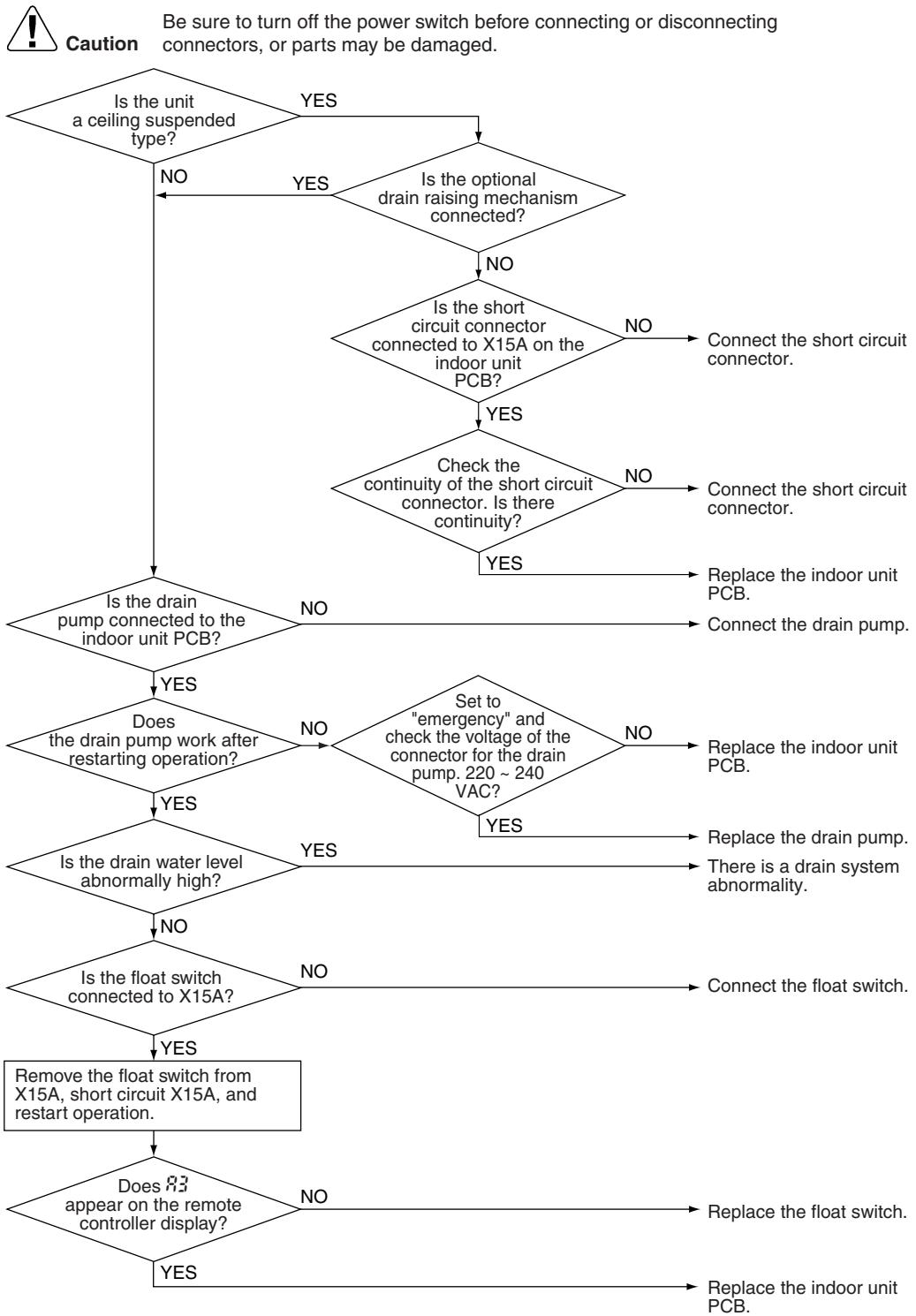
flowchart
graph TD
    A["Is the unit a ceiling suspended type?"] -->|NO| B{Is the optional drain raising mechanism connected?}
    A -->|YES| C["Is the short circuit connector connected to X15A on the indoor unit PCB?"]
    B -->|NO| D{Check the continuity of the short circuit connector. Is there continuity?}
    B -->|YES| E{Is the drain pump connected to the indoor unit PCB?}
    D -->|NO| F["Connect the short circuit connector."]
    D -->|YES| G["Replace the indoor unit PCB."]
    E -->|NO| H["Connect the drain pump."]
    E -->|YES| I{Does the drain pump work after restarting operation?}
    I -->|YES| J{Is the drain water level abnormally high?}
    I -->|NO| K{Is the float switch connected to X15A?}
    J -->|YES| L["Remove the float switch from X15A, short circuit X15A, and restart operation."]
    J -->|NO| M["Set to "emergency" and check the voltage of the connector for the drain pump. 220 ~ 240 VAC?"]
    K -->|YES| N["Replace the indoor unit PCB."]
    K -->|NO| O["There is a drain system abnormality."]
    L --> P["Remove the float switch from X15A, short circuit X15A, and restart operation."]
    M --> Q["Replace the float switch."]
    N --> R{Does it appear on the remote controller display?}
    O --> S["Replace the indoor unit PCB."]
    P --> T["Remove the float switch from X15A, short circuit X15A, and restart operation."]
    Q --> U["Remove the float switch from X15A, short circuit X15A, and restart operation."]
    R --> V["No"]
    S --> W["No"]
    T --> X["No"]
    U --> Y["No"]
(R17250)

Note: If R3 is detected by the indoor unit PCB which is not mounted with X15A, the indoor unit PCB is defective.
6.3 Fan Motor or Related Abnormality
| Remote Controller Display | 86 |
| Method of Malfunction Detection | The signal from the fan motor detects abnormal fan speed. |
| Malfunction Decision Conditions | When the fan rotations are not detected while the output voltage to the fan is at its maximum |
| Supposed Causes | ■ Defective indoor fan motor■ Broken or disconnected wire■ Defective contact■ Defective indoor unit PCB |
Troubleshooting FCQC, FFQ, FDBQ, FBQ Series

Caution
Be sure to turn off the power switch before connecting or disconnecting connectors, or parts may be damaged.
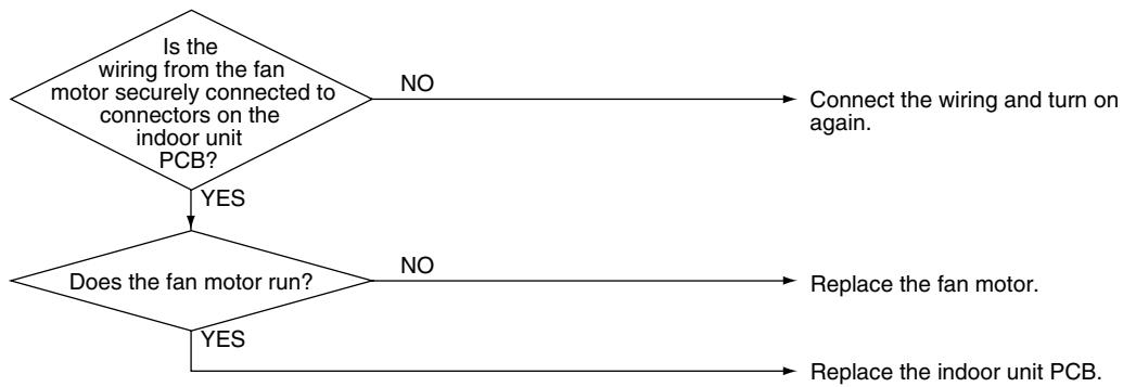
flowchart
graph TD
    A{Is the wiring from the fan motor securely connected to connectors on the indoor unit PCB?}
    B{Does the fan motor run?}
    A -->|NO| C["Connect the wiring and turn on again."]
    B -->|YES| D["Replace the fan motor."]
    B -->|YES| E["Replace the indoor unit PCB."]
(R11296)
Troubleshooting
FHQ Series

Caution
Be sure to turn off the power switch before connecting or disconnecting connectors, or parts may be damaged.
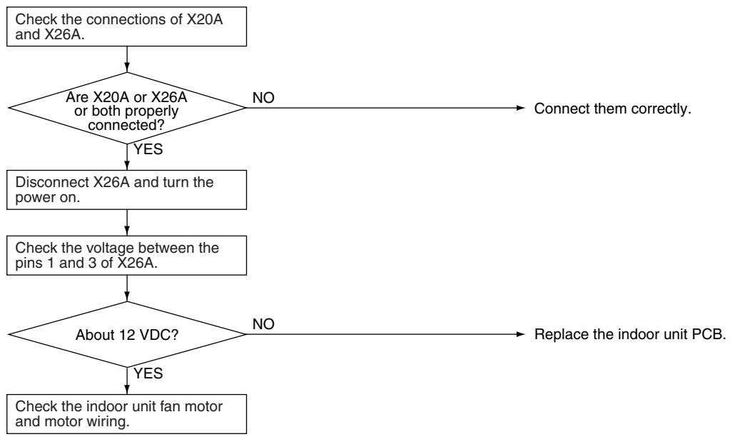
flowchart
graph TD
    A["Check the connections of X20A and X26A."] --> B{Are X20A or X26A or both properly connected?}
    B -->|NO| C["Connect them correctly."]
    B -->|YES| D["Disconnect X26A and turn the power on."]
    D --> E["Check the voltage between the pins 1 and 3 of X26A."]
    E --> F{About 12 VDC?}
    F -->|NO| G["Replace the indoor unit PCB."]
    F -->|YES| H["Check the indoor unit fan motor and motor wiring."]
(R12862)

Note: There is a possibility of open phase power supply, also check the power supply.
6.4 Swing Motor Lock (FHQ Series Only)
| Remote Controller Display | 87 |
| Method of Malfunction Detection | The error is detected by the limit switch when the motor turns. |
| Malfunction Decision Conditions | When the ON/OFF micro-switch for position detection cannot be reversed even though the swing motor is energized for a specified amount of time (about 30 seconds). |
| Supposed Causes | ■ Defective swing motor■ Defective micro-switch■ Disconnection of connector■ Defective indoor unit PCB |
Troubleshooting
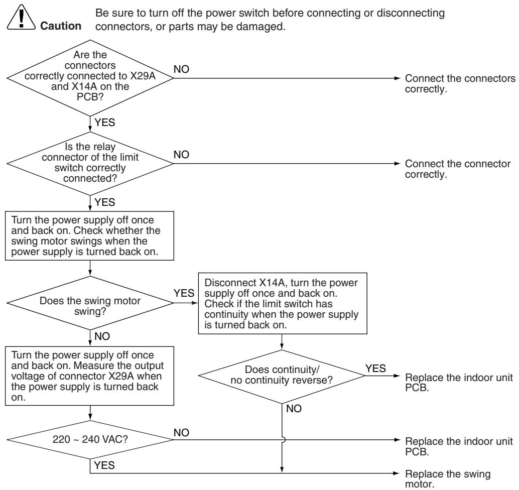
flowchart
graph TD
    A{Are the connectors correctly connected to X29A and X14A on the PCB?}
    B{Is the relay connector of the limit switch correctly connected?}
    C["Turn the power supply off once and back on. Check whether the swing motor swings when the power supply is turned back on."] --> D{Does the swing motor swing?}
    D -->|YES| E["Disconnect X14A, turn the power supply off once and back on.<br>Check if the limit switch has continuity when the power supply is turned back on."]
    D -->|NO| F["Turn the power supply off once and back on. Measure the output voltage of connector X29A when the power supply is turned back on."]
    E --> G{Does continuity/no continuity reverse?}
    F --> G
    G -->|YES| H["Replace the indoor unit PCB."]
    G -->|NO| I["Replace the indoor unit PCB."]
    G -->|NO| J["Replace the swing motor."]
    I --> K["Replace the swing motor."]
    J --> K
    K --> L{220 ~ 240 VAC?}
    L -->|YES| M["Replace the indoor unit PCB."]
    L -->|NO| N["Replace the indoor unit PCB."]
    M --> O["Connect the connectors correctly."]
    N --> P["Connect the connector correctly."]
(R17251)
6.5 Drain System Abnormality
| Remote Controller Display | RF |
| Method of Malfunction Detection | Water leakage is detected based on the float switch ON/OFF changeover while the compressor is not operating. |
| Malfunction Decision Conditions | When the float switch changes from ON to OFF while the compressor is OFF |
| Supposed Causes | ■ Error in the drain pipe installation■ Defective float switch■ Defective indoor unit PCB |
Troubleshooting
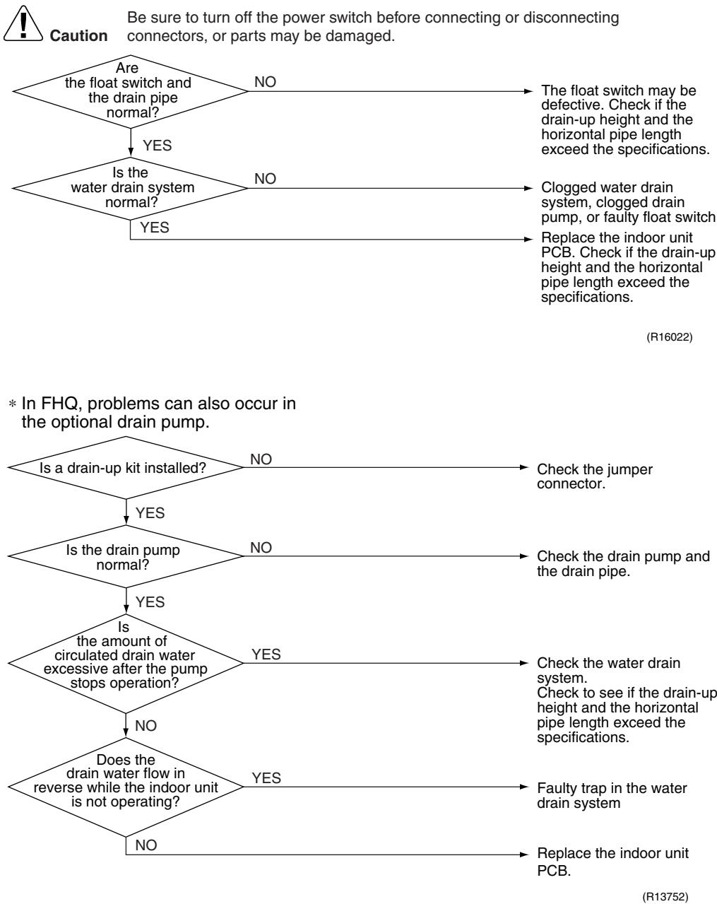
flowchart
graph TD
    A["Are the float switch and the drain pipe normal?"] -->|YES| B{Is the water drain system normal?}
    A -->|NO| C["The float switch may be defective. Check if the drain-up height and the horizontal pipe length exceed the specifications."]
    B -->|YES| D{Is a drain-up kit installed?}
    B -->|NO| E["Clogged water drain system, clogged drain pump, or faulty float switch"]
    B -->|YES| F["Replace the indoor unit PCB. Check if the drain-up height and the horizontal pipe length exceed the specifications."]
    D -->|YES| G{Is the drain pump normal?}
    D -->|NO| H["Check the jumper connector."]
    G -->|YES| I{Is the amount of circulated drain water excessive after the pump stops operation?}
    G -->|NO| J["Check the drain pump and the drain pipe."]
    I -->|YES| K{Does the drain water flow in reverse while the indoor unit is not operating?}
    I -->|NO| L["Check the water drain system. Check to see if the drain-up height and the horizontal pipe length exceed the specifications."]
    J --> M["Faulty trap in the water drain system"]
    J --> N["Replace the indoor unit PCB."]
6.6 Thermistor or Related Abnormality (SA Indoor Unit)
| Remote Controller Display | £4, £9 |
| Method of Malfunction Detection | The temperatures detected by the thermistors determine thermistor errors. |
| Malfunction Decision Conditions | The thermistor input is more than 4.96 V or less than 0.04 V during compressor operation. |
| Supposed Causes | ■ Disconnection of connector■ Defective thermistor■ Defective indoor unit PCB |
Troubleshooting

Check No.01
Refer to P.325
If the cause of the problem is related to the thermistors, the thermistors should be checked prior to changing the indoor unit PCB.
To check the thermistors, proceed as follows:
| Step | Action |
| 1 | Disconnect the thermistor from the indoor unit PCB. |
| 2 | Read the temperature and the resistance value. |
| 3 | Check if the measured values correspond with the values in the table of thermistor resistance check. |
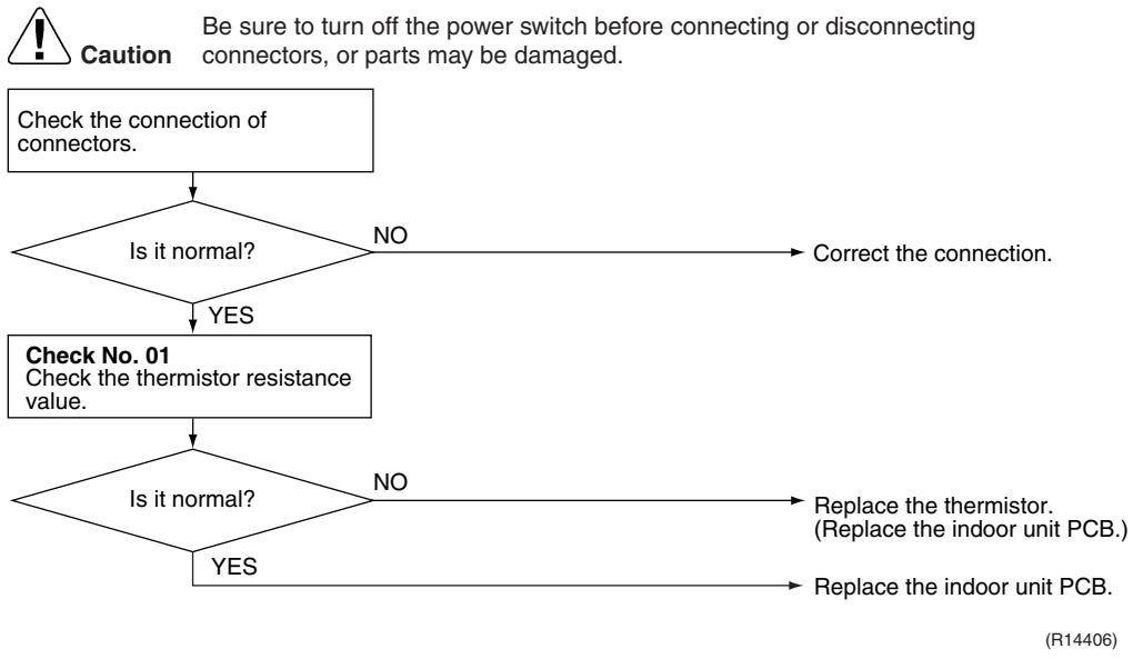
flowchart
graph TD
    A["Check the connection of connectors."] --> B{Is it normal?}
    B -->|NO| C["Correct the connection."]
    B -->|YES| D["Check No. 01<br>Check the thermistor resistance value."]
    D --> E{Is it normal?}
    E -->|NO| F["Replace the thermistor.<br>(Replace the indoor unit PCB.)"]
    E -->|YES| G["Replace the indoor unit PCB."]
C4: Indoor heat exchanger thermistor (R2T, R3T)
C9 : Room temperature thermistor (R1T)
6.7 Remote Controller Thermistor Abnormality
| Remote Controller Display | CJ |
| Method of Malfunction Detection | Even if remote controller thermistor is faulty, system is possible to operate by system thermistor. Malfunction detection is carried out by the temperature detected by remote controller thermistor. |
| Malfunction Decision Conditions | When the remote controller thermistor becomes disconnected or shorted while the unit is running. |
| Supposed Causes | ■ Defective thermistor■ Broken wire |
Troubleshooting
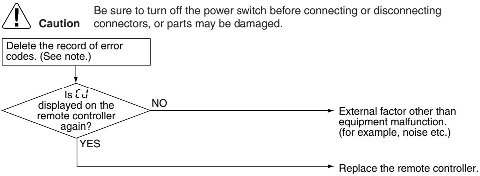
flowchart
graph TD
    A["Delete the record of error codes. (See note.)"] --> B{Is this displayed on the remote controller again?}
    B -->|YES| C["Replace the remote controller."]
    B -->|NO| D["External factor other than equipment malfunction. (for example, noise etc.)"]
    D --> E["Be sure to turn off the power switch before connecting or disconnecting connectors, or parts may be damaged."]
(R17252)

Note: To delete the record of error codes, press the [ON/OFF] button for 4 seconds or more while the error code is displayed in the inspection mode.
6.8 Signal Transmission Error (between Indoor Unit and Remote Controller)
| Remote Controller Display | UIS |
| Method of Malfunction Detection | Microcomputer checks if transmission between indoor unit and remote controller is normal. |
| Malfunction Decision Conditions | Normal transmission does not continue for specified period. |
| Supposed Causes | ■ Connection of 2 main remote controllers (when using 2 remote controllers)■ Defective indoor unit PCB■ Defective remote controller■ Transmission error caused by noise |
Troubleshooting
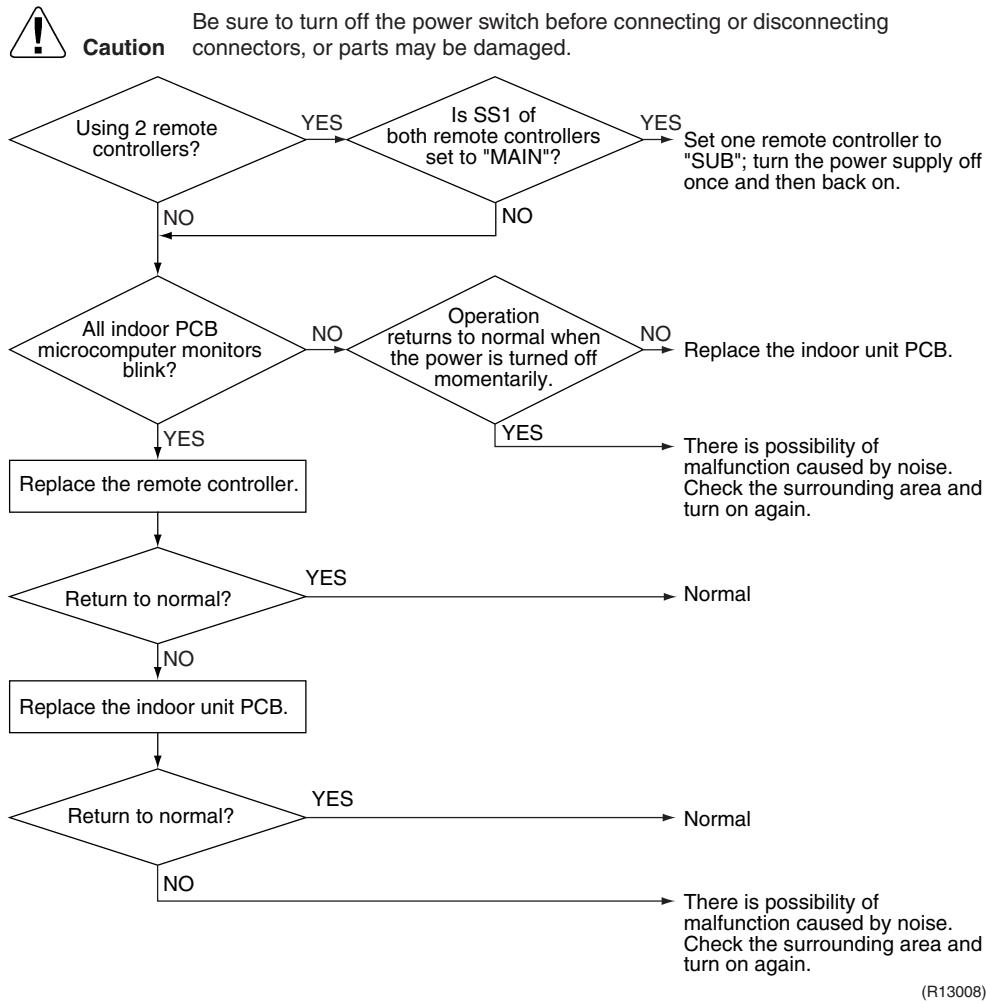
flowchart
graph TD
    A["Using 2 remote controllers?"] -->|NO| B{All indoor PCB microcomputer monitors blink?}
    A -->|YES| C{Is SS1 of both remote controllers set to "MAIN"?}
    C -->|NO| B
    C -->|YES| D["Set one remote controller to "SUB"; turn the power supply off once and then back on."]
    B -->|NO| E{Operation returns to normal when the power is turned off momentarily.}
    E -->|NO| F["Replace the indoor unit PCB."]
    E -->|YES| G["Replace the remote controller."]
    G --> H{Return to normal?}
    H -->|NO| I["Replace the indoor unit PCB."]
    H -->|YES| J["Normal"]
    I --> K{Return to normal?}
    K -->|NO| L["There is possibility of malfunction caused by noise. Check the surrounding area and turn on again."]
    K -->|YES| M["There is possibility of malfunction caused by noise. Check the surrounding area and turn on again."]
6.9 Signal Transmission Error (between MAIN Remote Controller and SUB Remote Controller)
| Remote Controller Display | 118 |
| Method of Malfunction Detection | In case of controlling with 2 remote controllers, check the system using micro-computer if signal transmission between indoor unit and remote controller (main and sub) is normal. |
| Malfunction Decision Conditions | Normal transmission does not continue for specified period. |
| Supposed Causes | ■ Remote controller is set to “SUB” when using 1 remote controller■ Connection of 2 sub remote controllers (when using 2 remote controllers)■ Defective remote controller PCB |
Troubleshooting
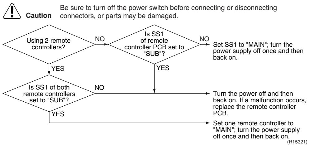
flowchart
graph TD
    A["Using 2 remote controllers?"] -->|NO| B{Is SS1 of remote controller PCB set to "SUB"?}
    B -->|YES| C{Is SS1 of both remote controllers set to "SUB"?}
    B -->|NO| D["Set SS1 to "MAIN"; turn the power supply off once and then back on."]
    C -->|YES| E["Turn the power off and then back on. If a malfunction occurs, replace the remote controller PCB."]
    C -->|NO| F["Set one remote controller to "MAIN"; turn the power supply off once and then back on."]
6.10 Field Setting Abnormality
| Remote Controller Display | U19 |
| Method of Malfunction Detection | |
| Malfunction Decision Conditions | Incorrect field setting |
| Supposed Causes | ■ Defective indoor unit PCB■ Defective outdoor unit PCB■ Defective power supply PCB■ Indoor-outdoor, indoor-indoor unit transmission wiring■ Defective remote controller wiring |
Troubleshooting
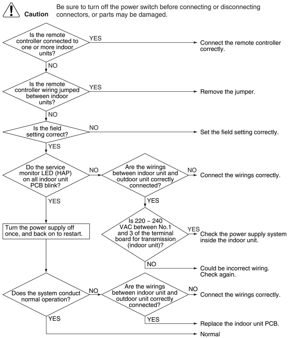
flowchart
graph TD
    A{Is the remote controller connected to one or more indoor units?} -->|NO| B{Is the remote controller wiring jumped between indoor units?}
    B -->|YES| C["Connect the remote controller correctly."]
    B -->|NO| D{Is the field setting correct?}
    D -->|YES| E{Do the service monitor LED (HAP) on all indoor unit PCB blink?}
    E -->|YES| F["Turn the power supply off once, and back on to restart."]
    E -->|NO| G{Are the wirings between indoor unit and outdoor unit correctly connected?}
    G -->|YES| H{Is 220 ~ 240 VAC between No.1 and 3 of the terminal board for transmission (indoor unit)?}
    G -->|NO| I{Are the wirings between indoor unit and outdoor unit correctly connected?}
    H -->|YES| J["Check the power supply system inside the indoor unit."]
    H -->|NO| K["Could be incorrect wiring. Check again."]
    I -->|YES| L["Replace the indoor unit PCB."]
    I -->|NO| M["Normal"]
    J --> N["Be sure to turn off the power switch before connecting or disconnecting connectors, or parts may be damaged."]
    K --> N
    L --> N
    M --> N
(R17253)
7. Troubleshooting for Outdoor Unit
7.1 Refrigerant Shortage
| Remote Controller Display | LED | |||
| Outdoor Unit LED Display | A ⚡ 1 ⚡ 2 ⚡ 3 ⚡ 4 ⚡ 5 ⚡ | |||
| Method of Malfunction Detection | Refrigerant shortage detection I:Refrigerant shortage is detected by checking the input current value and the compressor output frequency. If the refrigerant is short, the input current is smaller than the normal value. | |||
| Refrigerant shortage detection II:Refrigerant shortage is detected by checking the discharge pipe temperature and the opening of the outdoor electronic expansion valve. If the refrigerant is short, the discharge pipe temperature tends to rise. | ||||
| Malfunction Decision Conditions | Refrigerant shortage detection I:The following conditions continue for 7 minutes.◆ DC current ≤ A × Compressor output frequency + B◆ Output frequency > C | |||
| A (−) | B (A) | C (Hz) | ||
| 40/50/52/58 class | 0.01 | 0.3 | 54 | |
| 68/75 class | 0.035 | 0.5 | 55 | |
| 80/90 class | 0.027 | 2.0 | 40 | |
| Refrigerant shortage detection II:The following conditions continue for 80 seconds.◆ Opening of the outdoor electronic expansion valve ≥ D◆ Discharge pipe temperature > E × target discharge pipe temperature + F | ||||
| D (pulse) | E (−) | F (°C) | ||
| Cooling | 450 | 255/256 | 20 | |
| Heating | 40 | |||
| ■ If the error repeats, the system is shut down.■ Reset condition: Continuous run for about 60 minutes without any other error | ||||
| Supposed Causes | ■ Disconnection of the discharge pipe thermistor, indoor or outdoor heat exchanger thermistor, room or outdoor temperature thermistor■ Closed stop valve■ Refrigerant shortage (refrigerant leakage)■ Poor compression performance of compressor■ Defective outdoor electronic expansion valve | |||
Troubleshooting

Check No.01
Refer to P.325

Check No.12
Refer to P.329

Caution
Be sure to turn off the power switch before connecting or disconnecting connectors, or parts may be damaged.
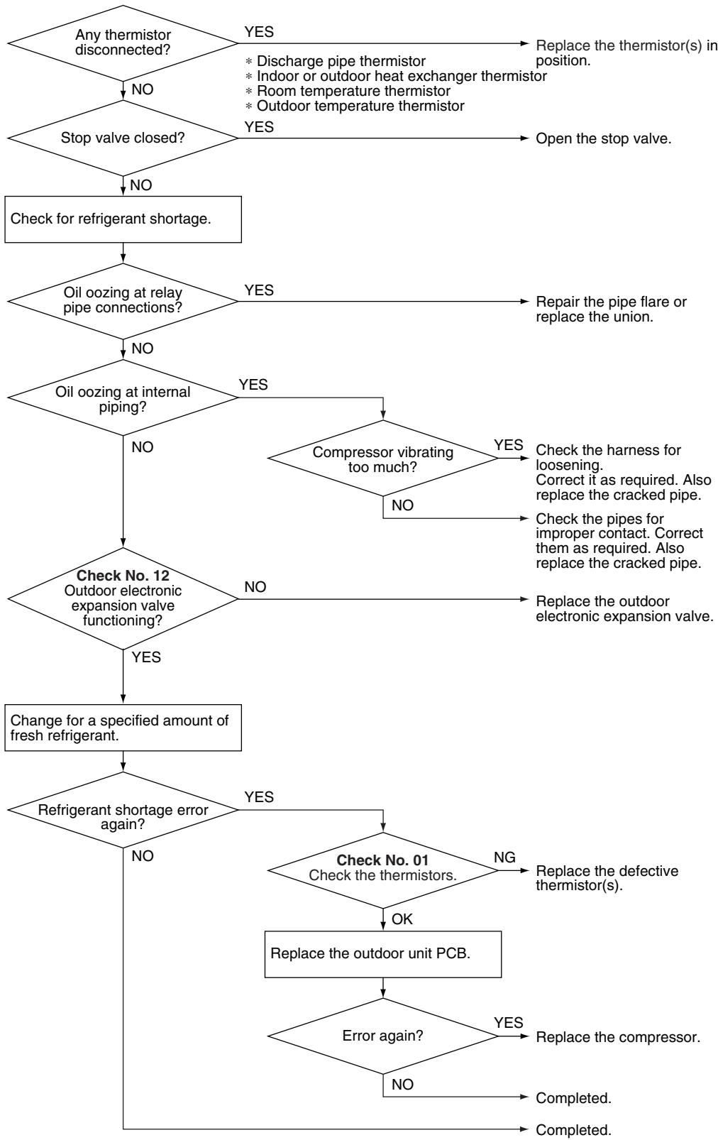
flowchart
graph TD
    A{Any thermistor disconnected?} -->|YES| B["Replace the thermistor(s) in position."]
    A -->|NO| C{Stop valve closed?}
    C -->|YES| D["Open the stop valve."]
    C -->|NO| E["Check for refrigerant shortage."]
    E --> F{Oil oozing at relay pipe connections?}
    F -->|YES| G["Repair the pipe flare or replace the union."]
    F -->|NO| H{Oil oozing at internal piping?}
    H -->|YES| I{Compressor vibrating too much?}
    I -->|YES| J["Check the harness for loosening. Correct it as required. Also replace the cracked pipe."]
    I -->|NO| K["Check the pipes for improper contact. Correct them as required. Also replace the cracked pipe."]
    H -->|NO| L{Check No. 12 Outdoor electronic expansion valve functioning?}
    L -->|YES| M["Change for a specified amount of fresh refrigerant."]
    L -->|NO| N{Refrigerant shortage error again?}
    N -->|YES| O{Check No. 01 Check the thermistors.}
    O -->|NG| P["Replace the defective thermistor(s)."]
    O -->|OK| Q["Replace the outdoor unit PCB."]
    Q --> R{Error again?}
    R -->|YES| S["Replace the compressor."]
    R -->|NO| T["Completed."]
    R -->|No| U["Completed."]
    N --> V["No"]
(R17254)
7.2 Low-voltage Detection or Over-voltage Detection
| Remote Controller Display | U2 |
| Outdoor Unit LED Display | A ⏻ 1 ⏻ 2 ⬤ 3 ⬤ 4 ⏻ 5 ⬤ |
| Method of Malfunction Detection | ★ Indoor UnitThe zero-cross detection of the power supply is evaluated by the indoor unit PCB.★ Outdoor UnitLow-voltage detection:An abnormal voltage drop is detected by the DC voltage detection circuit.Over-voltage detection:An abnormal voltage rise is detected by the over-voltage detection circuit. |
| Malfunction Decision Conditions | ★ Indoor UnitThere is no zero-cross detection in approximately 10 seconds.★ Outdoor UnitLow-voltage detection:The voltage detected by the DC voltage detection circuit is below 150 V for 0.1 second.If the error repeats, the system is shut down.Reset condition: Continuous run for about 60 minutes without any other errorOver-voltage detection:An over-voltage signal is fed from the over-voltage detection circuit to the microcomputer.The compressor stops if the error occurs, and restarts automatically after 3-minute standby. |
| Supposed Causes | ■ Supply voltage is not as specified.Defective DC voltage detection circuitDefective over-voltage detection circuitDefective PAM control partDisconnection of compressor harnessNoiseMomentary fall of voltageMomentary power failureDefective indoor unit PCB |
Troubleshooting
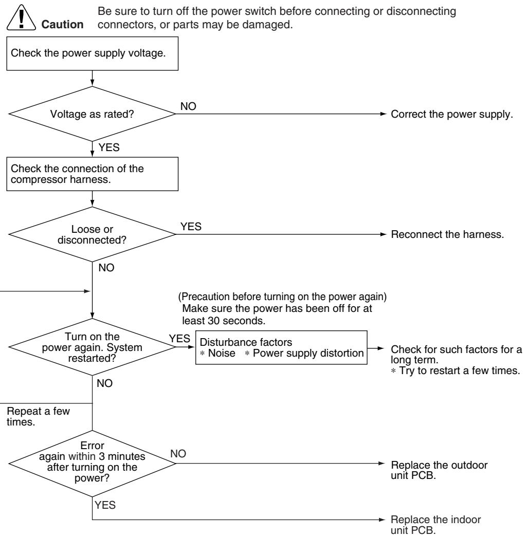
flowchart
graph TD
    A["Check the power supply voltage."] --> B{Voltage as rated?}
    B -->|NO| C["Correct the power supply."]
    B -->|YES| D["Check the connection of the compressor harness."]
    D --> E{Loose or disconnected?}
    E -->|NO| F["Turn on the power again. System restarted?"]
    E -->|YES| G["Reconnect the harness."]
    F --> H{Error again within 3 minutes after turning on the power?}
    H -->|NO| I["Repeat a few times."]
    H -->|YES| J["Replace the indoor unit PCB."]
    F --> K["Disturbance factors\n* Noise\n* Power supply distortion"]
    K --> L["Check for such factors for a long term.\n* Try to restart a few times."]
    L --> M["Replace the outdoor unit PCB."]
(R17269)
7.3 Signal Transmission Error (on Outdoor Unit PCB)
| Remote Controller Display | U7 |
| Outdoor Unit LED Display | A ⚙ 1 ⚙ 2 ⚙ 3 ⚙ 4 ⚙ 5 ⚙ |
| Method of Malfunction Detection | Communication error between microcomputer mounted on the main PCB and PM1. |
| Malfunction Decision Conditions | ■ The abnormality is determined when the data sent from the PM1 can not be received for 9 seconds.■ The error counter is reset when the data from the PM1 can be successfully received. |
| Supposed Causes | ■ Defective outdoor unit PCB |
Troubleshooting
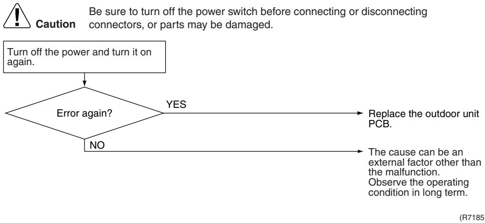
flowchart
graph TD
    A["Turn off the power and turn it on again."] --> B{Error again?}
    B -->|YES| C["Replace the outdoor unit PCB"]
    B -->|NO| D["The cause can be an external factor other than the malfunction. Observe the operating condition in long term."]
7.4 Unspecified Voltage (between Indoor Unit and Outdoor Unit) / Anti-icing Function in Other Rooms
| Remote Controller Display | UW, UW |
| Outdoor Unit LED Display | A 1 2 3 4 5 ● |
| Method of Malfunction Detection | A wrong connection is detected by checking the combination of indoor and outdoor units on the microcomputer. |
| Malfunction Decision Conditions | ■ Anti-icing function in other rooms■ Unspecified internal and/or external voltages■ Mismatching of indoor and outdoor units |
| Supposed Causes | ■ Anti-icing function in other rooms■ Wrong models interconnected■ Wrong indoor unit PCB or outdoor unit PCB mounted |
Troubleshooting
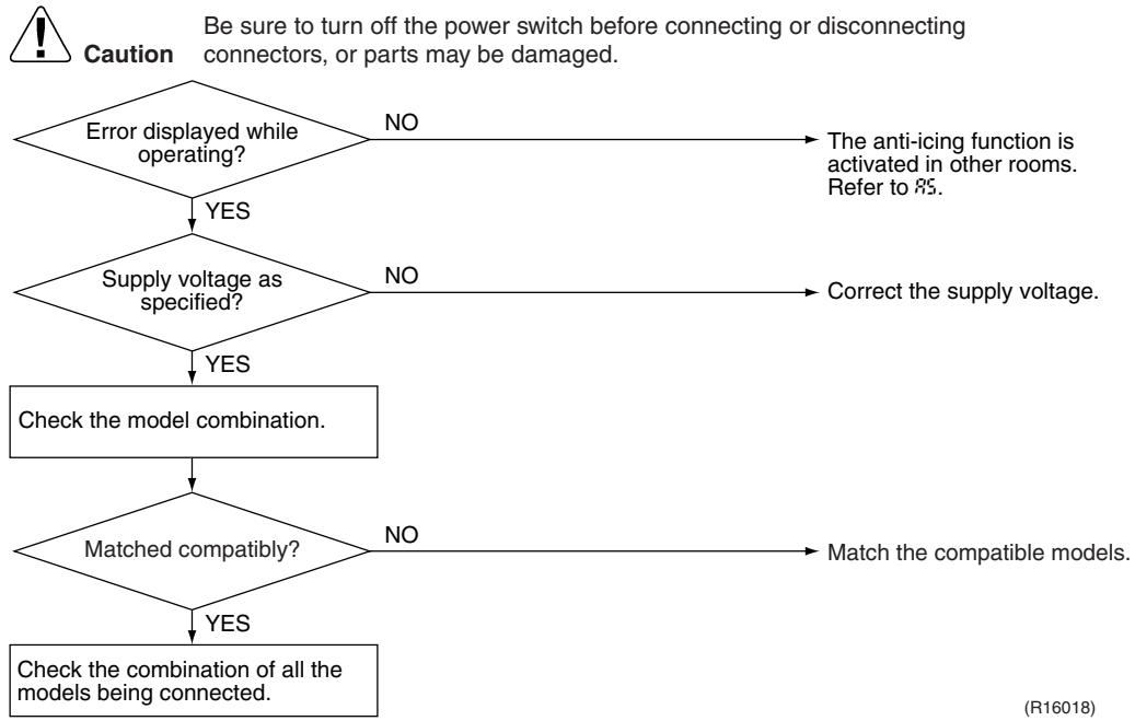
flowchart
graph TD
    A["Error displayed while operating?"] -->|YES| B{Supply voltage as specified?}
    A -->|NO| C["The anti-icing function is activated in other rooms. Refer to 85."]
    B -->|YES| D["Check the model combination."]
    B -->|NO| E["Correct the supply voltage."]
    D --> F{Matched compatibly?}
    F -->|YES| G["Check the combination of all the models being connected."]
    F -->|NO| H["Match the compatible models."]

Note: Refer to “Anti-icing function” on page 302 for detail.
7.5 Anti-icing Function
| Remote Controller Display | RS |
| Outdoor Unit LED Display | A ⏻ 1 ⏻ 2 ⬤ 3 ⏻ 4 ⏻ 5 ⬤ |
| Method of Malfunction Detection | During cooling operation, indoor unit icing is detected by checking the temperatures sensed by the indoor heat exchanger thermistor and room temperature thermistor that are located in a shut-down room. |
| Malfunction Decision Conditions | ■ In cooling operation, the both conditions (A) and (B) are met for 5 minutes.(A) Room temperature – Indoor heat exchanger temperature ≥ 10°C(B) Indoor heat exchanger temperature ≤ -1°C■ If the error repeats, the system is shut down.■ Reset condition: Continuous run for about 60 minutes without any other error |
| Supposed Causes | ■ Wrong wiring or piping■ Defective outdoor electronic expansion valve■ Short-circuited air■ Defective indoor heat exchanger thermistor■ Defective room temperature thermistor |
Troubleshooting

Check No.01
Refer to P.325

Check No.12
Refer to P.329
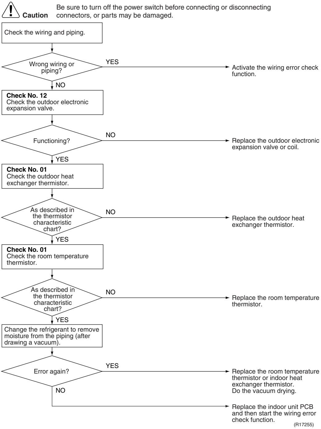
flowchart
graph TD
    A["Check the wiring and piping."] --> B{Wrong wiring or piping?}
    B -->|YES| C["Activate the wiring error check function."]
    B -->|NO| D["Check No. 12<br>Check the outdoor electronic expansion valve."]
    D --> E{Functioning?}
    E -->|NO| F["Replace the outdoor electronic expansion valve or coil."]
    E -->|YES| G["Check No. 01<br>Check the outdoor heat exchanger thermistor."]
    G --> H{As described in the thermistor characteristic chart?}
    H -->|NO| I["Replace the outdoor heat exchanger thermistor."]
    H -->|YES| J["Check No. 01<br>Check the room temperature thermistor."]
    J --> K{As described in the thermistor characteristic chart?}
    K -->|NO| L["Replace the room temperature thermistor."]
    K -->|YES| M["Change the refrigerant to remove moisture from the piping (after drawing a vacuum)."]
    M --> N{Error again?}
    N -->|YES| O["Replace the room temperature thermistor or indoor heat exchanger thermistor. Do the vacuum drying."]
    N -->|NO| P["Replace the indoor unit PCB and then start the wiring error check function."]
7.6 Outdoor Unit PCB Abnormality
| Remote Controller Display | E 1 |
| Outdoor Unit LED Display | A ⏻ 1 ⏱ 2 ⏱ 3 ⏱ 4 ⬤ 5 ⬤ |
| Method of Malfunction Detection | Detect within the program of the microcomputer. |
| Malfunction Decision Conditions | The program of the microcomputer is in abnormal running order. |
| Supposed Causes | ■ Defective outdoor unit PCB■ Noise■ Momentary fall of voltage■ Momentary power failure |
Troubleshooting
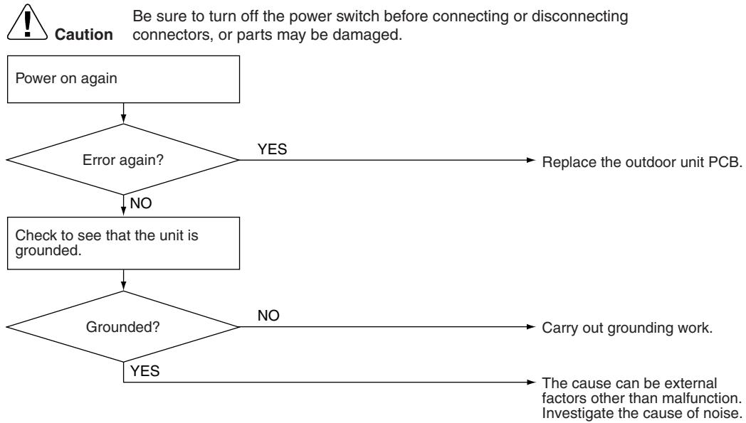
flowchart
graph TD
    A["Power on again"] --> B{Error again?}
    B -->|YES| C["Replace the outdoor unit PCB."]
    B -->|NO| D["Check to see that the unit is grounded."]
    D --> E{Grounded?}
    E -->|NO| F["Carry out grounding work."]
    E -->|YES| G["The cause can be external factors other than malfunction. Investigate the cause of noise."]
(R7183)
7.7 OL Activation (Compressor Overload)
| Remote Controller Display | ES |
| Outdoor Unit LED Display | A 1 2 3 4 5 ● |
| Method of Malfunction Detection | A compressor overload is detected through compressor OL. |
| Malfunction Decision Conditions | ■ If the error repeats, the system is shut down.■ Reset condition: Continuous run for about 60 minutes without any other error* The operating temperature condition is not specified. |
| Supposed Causes | ■ Defective discharge pipe thermistor■ Defective outdoor electronic expansion valve or coil■ Defective four way valve or coil■ Defective outdoor unit PCB■ Refrigerant shortage■ Water mixed in refrigerant■ Defective stop valve |
Troubleshooting

Check No.01
Refer to P.325

Check No.12
Refer to P.329

Check No.13
Refer to P.330

Check No.14
Refer to P.330
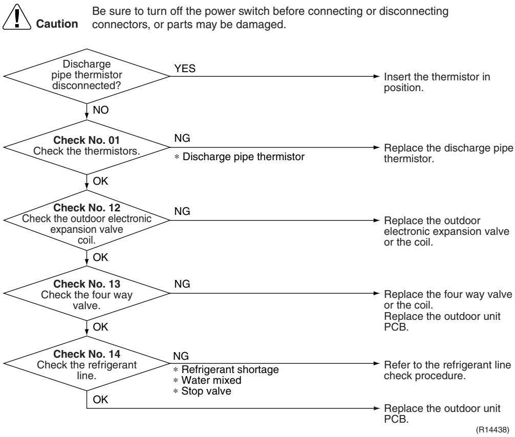
flowchart
graph TD
    A["Discharge pipe thermistor disconnected?"] -->|NO| B["Check No. 01"]
    B -->|NG| C["* Discharge pipe thermistor"]
    B -->|NG| D["Replace the discharge pipe thermistor."]
    B -->|NG| E["Check No. 12"]
    E -->|OK| F["Check the outdoor electronic expansion valve coil."]
    E -->|NG| G["Replace the outdoor electronic expansion valve or the coil."]
    E -->|NG| H["Check No. 13"]
    H -->|OK| I["Check the four way valve."]
    H -->|NG| J["Replace the four way valve or the coil. Replace the outdoor unit PCB."]
    H -->|OK| K["Check No. 14"]
    K -->|OK| L["Check the refrigerant line."]
    K -->|NG| M["* Refrigerant shortage<br>* Water mixed<br>* Stop valve"]
    K -->|NG| N["Refer to the refrigerant line check procedure."]
    K -->|OK| O["Replace the outdoor unit PCB."]
7.8 Compressor Lock
| Remote Controller Display | E6 |
| Outdoor Unit LED Display | A ⚙ 1 ⚙ 2 ⚙ 3 ⚙ 4 ⚙ 5 ⚙ |
| Method of Malfunction Detection | A compressor lock is detected by checking the compressor running condition through the position detection circuit. |
| Malfunction Decision Conditions | ■ Judging from the current waveform generated when high-frequency voltage is applied to the compressor.■ If the error repeats, the system is shut down.■ Reset condition: Continuous run for about 5 minutes without any other error |
| Supposed Causes | ■ Compressor locked■ Compressor harness disconnected |
Troubleshooting

Check No.15
Refer to P.331

Caution
Be sure to turn off the power switch before connecting or disconnecting connectors, or parts may be damaged.
(Precaution before turning on the power again)
Make sure the power has been off for at least 30 seconds.
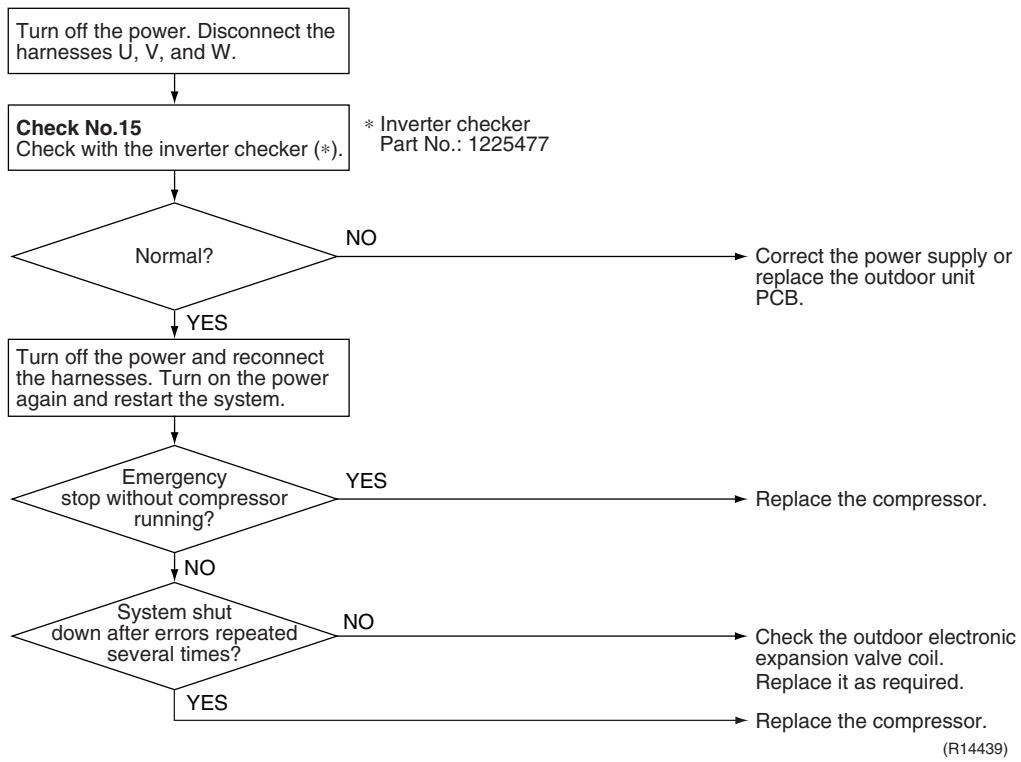
flowchart
graph TD
    A["Turn off the power. Disconnect the harnesses U, V, and W."] --> B["Check No.15\nCheck with the inverter checker (*)."]
    B --> C{Normal?}
    C -->|NO| D["Correct the power supply or replace the outdoor unit PCB."]
    C -->|YES| E["Turn off the power and reconnect the harnesses. Turn on the power again and restart the system."]
    E --> F{Emergency stop without compressor running?}
    F -->|YES| G["Replace the compressor."]
    F -->|NO| H["System shut down after errors repeated several times?"]
    H --> I{System shut down after errors repeated several times?}
    I -->|NO| J["Check the outdoor electronic expansion valve coil.\nReplace it as required."]
    I -->|YES| K["Replace the compressor."]
    D --> L["* Inverter checker\nPart No.: 1225477"]
7.9 DC Fan Lock
| Remote Controller Display | E7 |
| Outdoor Unit LED Display | A ⏻ 1 ⚙ 2 ⚙ 3 ⚙ 4 ⚙ 5 ● |
| Method of Malfunction Detection | An error is determined with the high-voltage fan motor rotation speed detected by the Hall IC. |
| Malfunction Decision Conditions | ■ The fan does not start in 30 seconds even when the fan motor is running.■ If the error repeats, the system is shut down.■ Reset condition: Continuous run for about 5 minutes without any other error |
| Supposed Causes | ■ Disconnection of the fan motor■ Foreign matter stuck in the fan■ Defective fan motor■ Defective outdoor unit PCB |
Troubleshooting

Check No.16
Refer to P.332
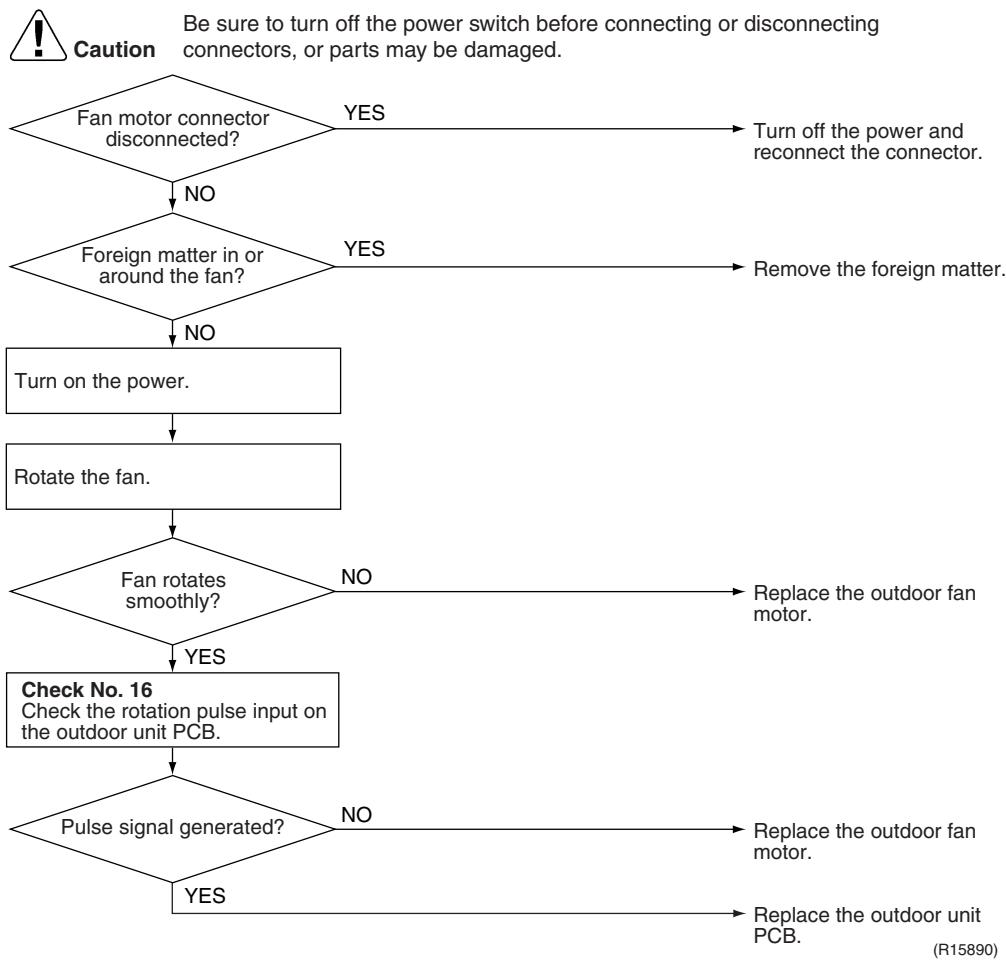
flowchart
graph TD
    A{Fan motor connector disconnected?} -->|NO| B{Foreign matter in or around the fan?}
    B -->|NO| C["Turn on the power."]
    B -->|YES| D["Remove the foreign matter."]
    C --> E["Rotate the fan."]
    E --> F{Fan rotates smoothly?}
    F -->|NO| G["Replace the outdoor fan motor."]
    F -->|YES| H["Check No. 16 Check the rotation pulse input on the outdoor unit PCB."]
    H --> I{Pulse signal generated?}
    I -->|NO| J["Replace the outdoor fan motor."]
    I -->|YES| K["Replace the outdoor unit PCB."]
    D --> L["Turn off the power and reconnect the connector."]
7.10 Input Overcurrent Detection
| Remote Controller Display | 88 |
| Outdoor Unit LED Display | A ⏻ 1 ⬤ 2 ⚙ 3 ⬤ 4 ⚙ 5 ⬤ |
| Method of Malfunction Detection | Detected by checking the input current value |
| Malfunction Decision Conditions | ■ The input current is at a certain value (depending on the condition) for 2.5 seconds.■ The compressor halts if the error occurs, and restarts automatically after 3-minute standby. |
| Supposed Causes | ■ Outdoor temperature is out of operation range.■ Defective compressor■ Defective power module■ Defective outdoor unit PCB■ Short circuit |
Troubleshooting

Check No.15
Refer to P.331

Check No.17
Refer to P.333

Check No.18
Refer to P.333
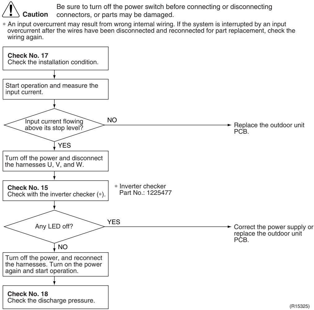
flowchart
graph TD
    A["Check No. 17\nCheck the installation condition."] --> B["Start operation and measure the input current."]
    B --> C{Input current flowing above its stop level?}
    C -->|NO| D["Replace the outdoor unit PCB."]
    C -->|YES| E["Turn off the power and disconnect the harnesses U, V, and W."]
    E --> F["Check No. 15\nCheck with the inverter checker (*)."]
    F --> G{Any LED off?}
    G -->|YES| H["Correct the power supply or replace the outdoor unit PCB."]
    G -->|NO| I["Turn off the power, and reconnect the harnesses. Turn on the power again and start operation."]
    I --> J["Check No. 18\nCheck the discharge pressure."]
7.11 Discharge Pipe Temperature Control
| Remote Controller Display | F3 | ||
| Outdoor Unit LED Display | A ⚙ 1 ⚙ 2 ⚙ 3 ⚙ 4 ⚙ 5 ⚙ | ||
| Method of Malfunction Detection | Detected by the discharge pipe thermistor | ||
| Malfunction Decision Conditions | ■ If the temperature detected by the discharge pipe thermistor rises above A °C, the compressor stops.■ The error is cleared when the discharge pipe temperature is dropped below B °C. | ||
| A (°C) | B (°C) | ||
| 40/50/52/58 class | 110 | 95 | |
| 68/75/80/90 class | 120 | 107 | |
| ■ If the error repeats, the system is shut down.■ Reset condition: Continuous run for about 60 minutes without any other error | |||
| Supposed Causes | ■ Defective discharge pipe thermistor(Defective outdoor heat exchanger thermistor or outdoor temperature thermistor)■ Defective outdoor electronic expansion valve or coil■ Refrigerant shortage■ Defective four way valve■ Water mixed in refrigerant■ Defective stop valve■ Defective outdoor unit PCB | ||
Troubleshooting

Check No.01
Refer to P.325

Check No.12
Refer to P.329

Check No.14
Refer to P.330
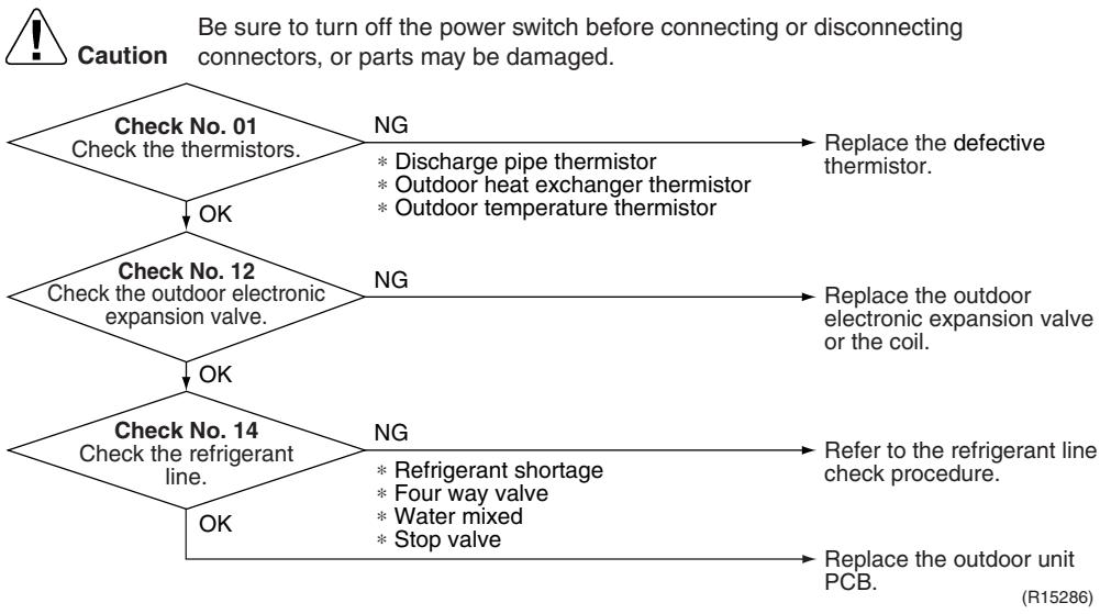
flowchart
graph TD
    A["Check No. 01\nCheck the thermistors."] -->|NG\n* Discharge pipe thermistor\n* Outdoor heat exchanger thermistor\n* Outdoor temperature thermistor| B["Replace the defective thermistor."]
    A -->|OK| C["Check No. 12\nCheck the outdoor electronic expansion valve."]
    C -->|NG| D["Replace the outdoor electronic expansion valve or the coil."]
    C -->|OK| E["Check No. 14\nCheck the refrigerant line."]
    E -->|NG\n* Refrigerant shortage\n* Four way valve\n* Water mixed\n* Stop valve| F["Refer to the refrigerant line check procedure."]
    E -->|OK| G["Replace the outdoor unit PCB."]
7.12 High Pressure Control in Cooling
| Remote Controller Display | FE |
| Outdoor Unit LED Display | A ⚙ 1 ⚙ 2 ⚙ 3 ⚙ 4 ⚙ 5 ⚙ |
| Method of Malfunction Detection | High-pressure control (operation halt, frequency drop, etc.) is activated in cooling mode if the temperature sensed by the outdoor heat exchanger thermistor exceeds the limit. |
| Malfunction Decision Conditions | ■ The temperature sensed by the outdoor heat exchanger thermistor rises above about 65°C.■ The error is cleared when the temperature drops below about 50°C. |
| Supposed Causes | ■ The installation space is not large enough.■ Dirty outdoor heat exchanger■ Defective outdoor fan motor■ Defective stop valve■ Defective outdoor electronic expansion valve or coil■ Defective outdoor heat exchanger thermistor■ Defective outdoor unit PCB |
Troubleshooting

Check No.01
Refer to P.325

Check No.12
Refer to P.329

Check No.17
Refer to P.333

Check No.18
Refer to P.333

Check No.19
Refer to P.334

Caution
Be sure to turn off the power switch before connecting or disconnecting connectors, or parts may be damaged.
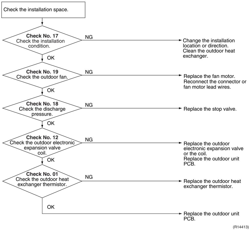
flowchart
graph TD
    A["Check the installation space."] --> B{Check No. 17 Check the installation condition.}
    B -->|NG| C["Change the installation location or direction. Clean the outdoor heat exchanger."]
    B -->|OK| D{Check No. 19 Check the outdoor fan.}
    D -->|NG| E["Replace the fan motor. Reconnect the connector or fan motor lead wires."]
    D -->|OK| F{Check No. 18 Check the discharge pressure.}
    F -->|NG| G["Replace the stop valve."]
    F -->|OK| H{Check No. 12 Check the outdoor electronic expansion valve coil.}
    H -->|NG| I["Replace the outdoor electronic expansion valve or the coil. Replace the outdoor unit PCB."]
    H -->|OK| J{Check No. 01 Check the outdoor heat exchanger thermistor.}
    J -->|NG| K["Replace the outdoor heat exchanger thermistor."]
    J -->|OK| L["Replace the outdoor unit PCB."]
7.13 Compressor Sensor System Abnormality
| Remote Controller Display | HD |
| Outdoor Unit LED Display | A 1 2 3 4 5 ● |
| Method of Malfunction Detection | ■ Fault condition is identified by the supply voltage and the DC voltage which is detected before the compressor startup.■ Fault condition is identified by the compressor current which is detected right after the compressor startup.■ If the error repeats, the system is shut down.■ Reset condition: Continuous run for about 5 minutes without any other error |
| Malfunction Decision Conditions | ■ The detected value of the supply voltage and the DC voltage is obviously low or high.■ The compressor current does not run when the compressor is started. |
| Supposed Causes | ■ Disconnection of reactor■ Disconnection of compressor harness■ Defective outdoor unit PCB■ Defective compressor |
Troubleshooting
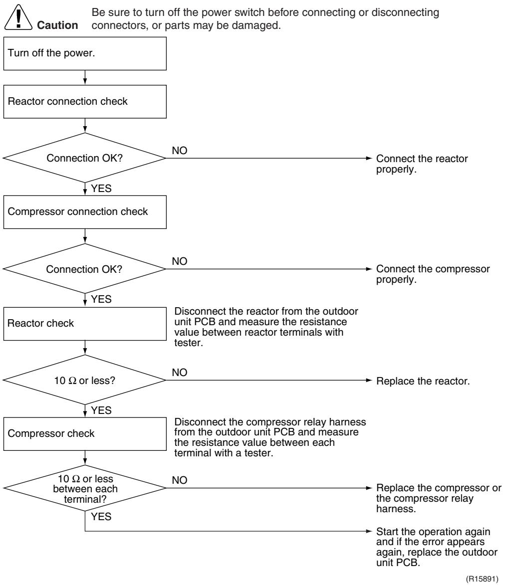
flowchart
graph TD
    A["Turn off the power."] --> B["Reactor connection check"]
    B --> C{Connection OK?}
    C -->|NO| D["Connect the reactor properly."]
    C -->|YES| E["Compressor connection check"]
    E --> F{Connection OK?}
    F -->|NO| G["Connect the compressor properly."]
    F -->|YES| H["Reactor check"]
    H --> I{10 Ω or less?}
    I -->|NO| J["Replace the reactor."]
    I -->|YES| K["Compressor check"]
    K --> L{10 Ω or less between each terminal?}
    L -->|NO| M["Replace the compressor or the compressor relay harness."]
    L -->|YES| N["Start the operation again and if the error appears again, replace the outdoor unit PCB."]
7.14 Position Sensor Abnormality
| Remote Controller Display | HIS |
| Outdoor Unit LED Display | A ⏻ 1 ⚙ 2 ⚙ 3 ⬤ 4 ⬤ 5 ⬤ |
| Method of Malfunction Detection | A compressor startup failure is detected by checking the compressor running condition through the position detection circuit. |
| Malfunction Decision Conditions | ■ If the error repeats, the system is shut down.■ Reset condition: Continuous run for about 5 minutes without any other error |
| Supposed Causes | ■ Disconnection of the compressor relay cable■ Defective compressor■ Defective outdoor unit PCB■ Start-up failure caused by the closed stop valve■ Input voltage is outside the specified range. |
Troubleshooting

Check No.15
Refer to P.331

Check No.18
Refer to P.333

Caution
Be sure to turn off the power switch before connecting or disconnecting connectors, or parts may be damaged.

flowchart
graph TD
    A["Turn off the power."] --> B["Check the power supply voltage."]
    B --> C{Voltage as rated?}
    C -->|NO| D["Correct the power supply."]
    C -->|YES| E["Check No. 18\nCheck the discharge pressure."]
    E --> F{OK?}
    F -->|NO| G["Replace the stop valve."]
    F -->|YES| H["Check the connection."]
    H --> I{Electrical components or compressor harnesses connected as specified?}
    I -->|NO| J["Reconnect the electrical components or compressor harnesses as specified."]
    I -->|YES| K["Turn on the power.\nCheck the electrolytic capacitor voltage."]
    K --> L{320 ± 50 VDC?}
    L -->|NO| M["Replace the outdoor unit PCB."]
    L -->|YES| N["Turn off the power. Disconnect the harnesses U, V, and W."]
    N --> O["Check No.15\nCheck with the inverter checker (*)."]
    O --> P{Any LED OFF?}
    P -->|YES| Q["Correct the power supply or replace the outdoor unit PCB."]
    P -->|NO| R["Replace the compressor."]
7.15 CT or Related Abnormality
| Remote Controller Display | 88 | ||
| Outdoor Unit LED Display | A 1 2 3 4 5 | ||
| Method of Malfunction Detection | A CT or related error is detected by checking the compressor running frequency and CT-detected input current. | ||
| Malfunction Decision Conditions | ■ The compressor running frequency is more than A Hz and input current is less than B A. | ||
| A (Hz) | B (A) | ||
| 40/50/52/58/68/75 class | 55 | 0.5 | |
| 80/90 class | 32 | 0.5 | |
| ■ If the error repeats, the system is shut down.■ Reset condition: Continuous run for about 60 minutes without any other error | |||
| Supposed Causes | ■ Defective power module■ Broken or disconnected wiring■ Defective reactor■ Defective outdoor unit PCB | ||
Troubleshooting

Check No.15
Refer to P.331

Check No.21
Refer to P.334

Caution
Be sure to turn off the power switch before connecting or disconnecting connectors, or parts may be damaged.
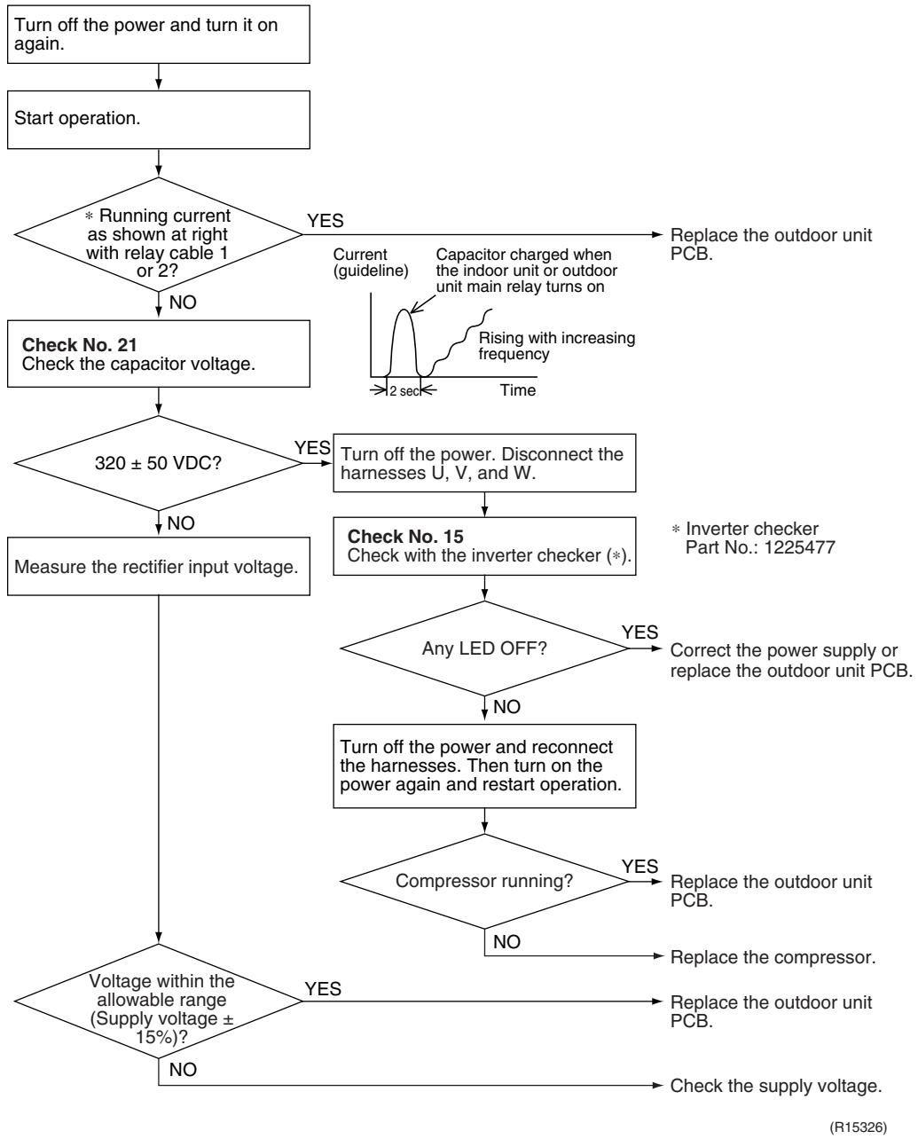
flowchart
graph TD
    A["Turn off the power and turn it on again."] --> B["Start operation."]
    B --> C{* Running current as shown at right with relay cable 1 or 2?}
    C -->|YES| D["Replace the outdoor unit PCB."]
    C -->|NO| E["Check No. 21 Check the capacitor voltage."]
    E --> F{320 ± 50 VDC?}
    F -->|YES| G["Turn off the power. Disconnect the harnesses U, V, and W."]
    F -->|NO| H["Measure the rectifier input voltage."]
    G --> I["Check No. 15 Check with the inverter checker (*)."]
    I --> J{Any LED OFF?}
    J -->|YES| K["Correct the power supply or replace the outdoor unit PCB."]
    J -->|NO| L["Turn off the power and reconnect the harnesses. Then turn on the power again and restart operation."]
    L --> M{Compressor running?}
    M -->|YES| N["Replace the outdoor unit PCB."]
    M -->|NO| O{Voltage within the allowable range (Supply voltage ± 15)?}
    O -->|YES| P["Replace the outdoor unit PCB."]
    O -->|NO| Q["Check the supply voltage."]
7.16 Thermistor or Related Abnormality (Outdoor Unit)
| Remote Controller Display | 49, 43, 46, 48, 49, 54 |
| Outdoor Unit LED Display | A ⚙ 1 ⚙ 2 ⚙ 3 ⚙ 4 ⚙ 5 ⚙ |
| Method of Malfunction Detection | This type of error is detected by checking the thermistor input voltage to the microcomputer. A thermistor error is detected by checking the temperature sensed by each thermistor. |
| Malfunction Decision Conditions | ■ The thermistor input is above 4.96 V or below 0.04 V with the power on. ■ 43 error is judged if the discharge pipe temperature is lower than the heat exchanger temperature. ■ The system is shut down if all the units are judged as the 48 error. |
| Supposed Causes | ■ Disconnection of the connector for the thermistor ■ Defective thermistor corresponding to the error code ■ Defective heat exchanger thermistor in the case of 43 error (outdoor heat exchanger thermistor in cooling operation, or indoor heat exchanger thermistor in heating operation) ■ Defective outdoor unit PCB |
Troubleshooting
In case of P4

Caution
Be sure to turn off the power switch before connecting or disconnecting connectors, or parts may be damaged.
Replace the outdoor unit PCB.
In case of H9, U3, U6, U8, U9

Caution
Be sure to turn off the power switch before connecting or disconnecting connectors, or parts may be damaged.
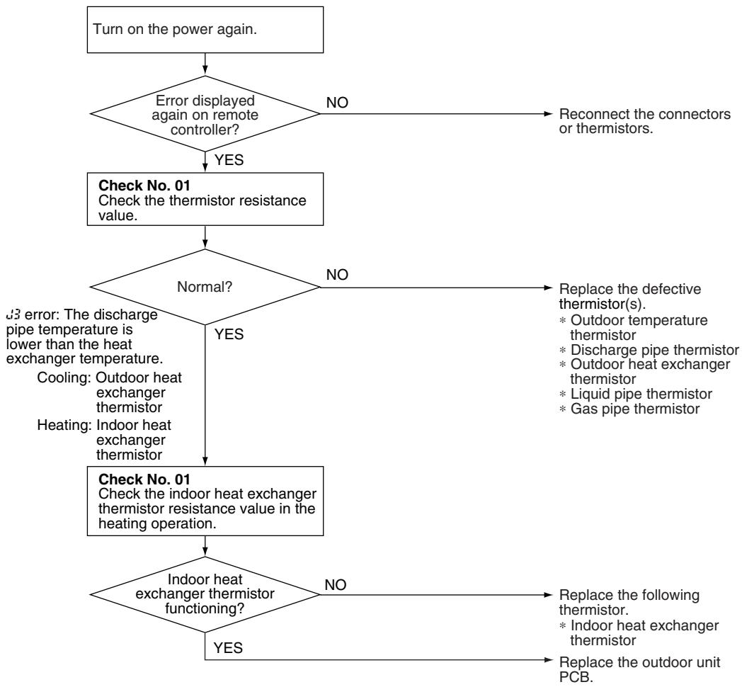
flowchart
graph TD
    A["Turn on the power again."] --> B{Error displayed again on remote controller?}
    B -->|NO| C["Reconnect the connectors or thermistors."]
    B -->|YES| D["Check No. 01\nCheck the thermistor resistance value."]
    D --> E{Normal?}
    E -->|NO| F["Replace the defective thermistor(s).\n* Outdoor temperature thermistor\n* Discharge pipe thermistor\n* Outdoor heat exchanger thermistor\n* Liquid pipe thermistor\n* Gas pipe thermistor"]
    E -->|YES| G["Check No. 01\nCheck the indoor heat exchanger thermistor resistance value in the heating operation."]
    G --> H{Indoor heat exchanger thermistor functioning?}
    H -->|NO| I["Replace the following thermistor.\n* Indoor heat exchanger thermistor"]
    H -->|YES| J["Replace the outdoor unit PCB."]
(R17164)
49 : Outdoor temperature thermistor
JB3 : Discharge pipe thermistor
JS : Outdoor heat exchanger thermistor
J8 : Liquid pipe thermistor
JS : Gas pipe thermistor
7.17 Electrical Box Temperature Rise
| Remote Controller Display | L3 | ||
| Outdoor Unit LED Display | A ⚙ 1 ⚙ 2 ⚙ 3 ⚙ 4 ⚙ 5 ⚙ | ||
| Method of Malfunction Detection | An electrical box temperature rise is detected by checking the radiation fin thermistor with the compressor off. | ||
| Malfunction Decision Conditions | ■ With the compressor off, the radiation fin temperature is above A °C.■ The error is cleared when the temperature drops below B °C.■ To cool the electrical components, the outdoor fan starts when the radiation fin temperature rises above C °C and stops when it drops below B °C. | ||
| A (°C) | B (°C) | C (°C) | |
| 100 | 70 | 85 | |
| Supposed Causes | ■ Defective outdoor fan motor■ Short circuit■ Defective radiation fin thermistor■ Disconnection of connector■ Defective outdoor unit PCB | ||
Troubleshooting

Check No.17
Refer to P.333

Check No.19
Refer to P.334
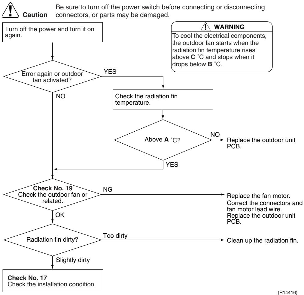
flowchart
graph TD
    A["Turn off the power and turn it on again."] --> B{Error again or outdoor fan activated?}
    B -->|YES| C["Check the radiation fin temperature."]
    B -->|NO| D{Check No. 19 Check the outdoor fan or related.}
    D -->|NG| E["Replace the fan motor. Correct the connectors and fan motor lead wire. Replace the outdoor unit PCB."]
    D -->|OK| F{Radiation fin dirty?}
    F -->|Too dirty| G["Clean up the radiation fin."]
    F -->|Slightly dirty| H["Check No. 17 Check the installation condition."]
    C --> I{Above A °C?}
    I -->|NO| J["Replace the outdoor unit PCB."]
    I -->|YES| D
    style A fill:#f9f,stroke:#333
    style H fill:#f9f,stroke:#333
| Remote Controller Display | L4 | ||
| Outdoor Unit LED Display | A ⚙ 1 ⚙ 2 ⚙ 3 ⚙ 4 ⚙ 5 ⚙ | ||
| Method of Malfunction Detection | A radiation fin temperature rise is detected by checking the radiation fin temperature with the compressor on. | ||
| Malfunction Decision Conditions | ■ The radiation fin temperature with the compressor on is above A °C.■ The error is cleared when the temperature drops below B °C | ||
| A (°C) | B (°C) | ||
| 40/50/52/58/68/75 class | 103 | 95 | |
| 80/90 class | 105 | 97 | |
| ■ If the error repeats, the system is shut down.■ Reset condition: Continuous run for about 60 minutes without any other error | |||
| Supposed Causes | ■ Defective outdoor fan motor■ Short circuit■ Defective radiation fin thermistor■ Disconnection of connector■ Defective outdoor unit PCB■ Silicon grease is not applied properly on the radiation fin after replacing the outdoor unit PCB. | ||
Troubleshooting

Check No.17
Refer to P.333

Check No.19
Refer to P.334

Caution
Be sure to turn off the power switch before connecting or disconnecting connectors, or parts may be damaged.
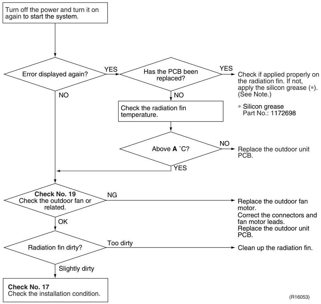
flowchart
graph TD
    A["Turn off the power and turn it on again to start the system."] --> B{Error displayed again?}
    B -->|NO| C{Check No. 19 Check the outdoor fan or related.}
    B -->|YES| D{Has the PCB been replaced?}
    D -->|NO| E["Check the radiation fin temperature."]
    D -->|YES| F["Check if applied properly on the radiation fin. If not, apply the silicon grease (*). (See Note.)"]
    E --> G{Above A °C?}
    G -->|NO| H["Replace the outdoor unit PCB."]
    G -->|YES| I{Radiation fin dirty?}
    I -->|Slightly dirty| J["Check No. 17 Check the installation condition."]
    I -->|TOO dirty| K["Clean up the radiation fin."]
    C --> L{OK}
    L --> M{Radiation fin dirty?}
    M -->|NG| N["Replace the outdoor fan motor. Correcting connectors and fan motor leads. Replace the outdoor unit PCB."]
    M -->|NO| O["Check the radiation fin temperature."]
| A (°C) | |
| 40/50/52/58/68/75 class | 103 |
| 80/90 class | 105 |

Note: Refer to “Application of silicon grease to a power transistor and a diode bridge” on page 423 for detail.
7.19 Output Overcurrent Detection
| Remote Controller Display | LS |
| Outdoor Unit LED Display | A ⚙ 1 ⚙ 2 ⚙ 3 ⚙ 4 ⚙ 5 ⚙ |
| Method of Malfunction Detection | An output overcurrent is detected by checking the current that flows in the inverter DC section. |
| Malfunction Decision Conditions | ■ A position signal error occurs while the compressor is running.■ A speed error occurs while the compressor is running.■ An output overcurrent signal is fed from the output overcurrent detection circuit to the microcomputer.■ If the error repeats, the system is shut down.■ Reset condition: Continuous run for about 5 minutes without any other error |
| Supposed Causes | ■ Poor installation condition■ Closed stop valve■ Defective power module■ Wrong internal wiring■ Abnormal power supply voltage■ Defective outdoor unit PCB■ Defective compressor |
Troubleshooting

Check No.15
Refer to P.331

Check No.17
Refer to P.333

Check No.18
Refer to P.333

Check No.22
Refer to P.335

Caution
Be sure to turn off the power switch before connecting or disconnecting connectors, or parts may be damaged.
* An output overcurrent may result from wrong internal wiring. If the system is interrupted by an output overcurrent after the wires have been disconnected and reconnected for part replacement, check the wiring again.
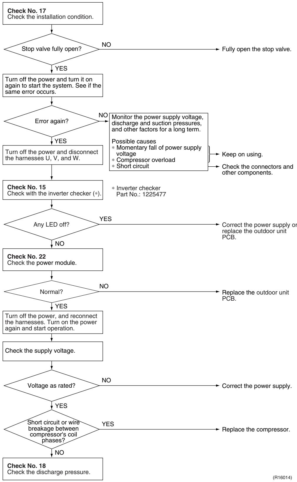
flowchart
graph TD
    A["Check No. 17\nCheck the installation condition."] --> B{Stop valve fully open?}
    B -->|NO| C["Fully open the stop valve."]
    B -->|YES| D["Turn off the power and turn it on again to start the system. See if the same error occurs."]
    D --> E{Error again?}
    E -->|NO| F["Monitor the power supply voltage, discharge and suction pressures, and other factors for a long term."]
    E -->|YES| G["Turn off the power and disconnect the harnesses U, V, and W."]
    F --> H["Possible causes\n* Momentary fall of power supply voltage\n* Compressor overload\n* Short circuit"]
    H --> I["Keep on using."]
    H --> J["Check the connectors and other components."]
    G --> K["Check No. 15\nCheck with the inverter checker (*)."]
    K --> L{Any LED off?}
    L -->|YES| M["Correct the power supply or replace the outdoor unit PCB."]
    L -->|NO| N["Check No. 22\nCheck the power module."]
    N --> O{Normal?}
    O -->|NO| P["Replace the outdoor unit PCB."]
    O -->|YES| Q["Turn off the power, and reconnect the harnesses. Turn on the power again and start operation."]
    Q --> R["Check the supply voltage."]
    R --> S{Voltage as rated?}
    S -->|NO| T["Correct the power supply."]
    S -->|YES| U{Short circuit or wire breakage between compressor's coil phases?}
    U -->|YES| V["Replace the compressor."]
    U -->|NO| W["Check No. 18\nCheck the discharge pressure."]
8. Check
8.1 Thermistor Resistance Check
Check No.01
Disconnect the connectors of the thermistors from the PCB, and measure the resistance of each thermistor using tester.
The relationship between normal temperature and resistance is shown in the table and the graphs below.
The data is for reference purpose only.
| Thermistor temperature (°C) | Resistance (kΩ) | |
| Room temperature thermistor for FTXS-K and CTXS-K series | Other thermistors | |
| -20 | 70.3 | 197.8 |
| -15 | 56.1 | 148.2 |
| -10 | 44.1 | 112.1 |
| -5 | 34.9 | 85.60 |
| 0 | 28.2 | 65.93 |
| 5 | 22.3 | 51.14 |
| 10 | 18.1 | 39.99 |
| 15 | 14.8 | 31.52 |
| 20 | 12.2 | 25.02 |
| 25 | 10.0 | 20.00 |
| 30 | 8.3 | 16.10 |
| 35 | 6.9 | 13.04 |
| 40 | 5.8 | 10.62 |
| 45 | 4.9 | 8.707 |
| 50 | 4.1 | 7.176 |
(R25°C = 10 kΩ, B = 3435 K) (R25°C = 20 kΩ, B = 3950 K)
Room temperature thermistor
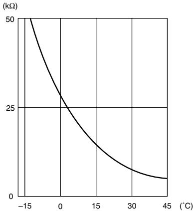
line
| Temperature (°C) | Resistance (kΩ) | | ---------------- | --------------- | | -15 | 50 | | 0 | 25 | | 15 | 10 | | 30 | 5 | | 45 | 2 |Other thermistors
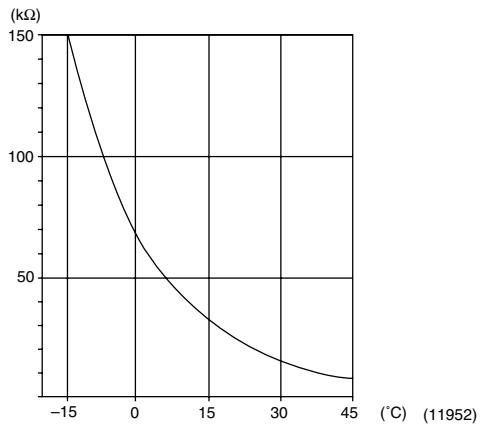
line
| Temperature (°C) | Resistance (kΩ) | | ---------------- | --------------- | | -15 | 150 | | 0 | 75 | | 15 | 37.5 | | 30 | 20 | | 45 | 10 |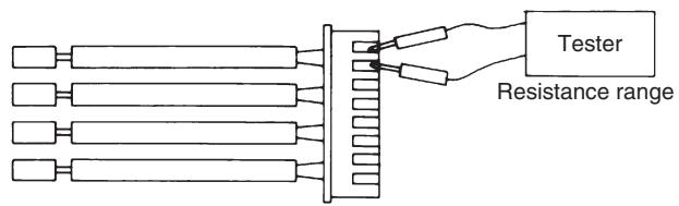
text_image
Tester Resistance range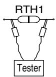
(R11906)
■ The room temperature thermistor is directly mounted on the display PCB. Remove the display PCB from the control PCB to measure the resistance.
■ When the indoor heat exchanger thermistor is soldered on the PCB, remove the thermistor and measure the resistance.
8.2 Fan Motor Connector Check
Check No.02
FTXG, FTXS-J, FTXS-G, FVXG, FVXS Series
- Check the connection of connector.
- Check motor power supply voltage output (pins 4 - 7).
- Check motor control voltage (pins 4 - 3).
- Check rotation command voltage output (pins 4 - 2).
- Check rotation pulse input (pins 4 - 1).
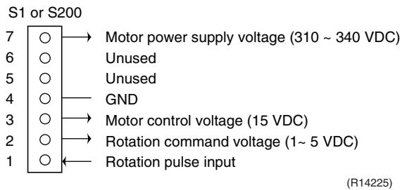
text_image
S1 or S200 7 ○ → Motor power supply voltage (310 ~ 340 VDC) 6 ○ ○ Unused 5 ○ ○ Unused 4 ○ — GND 3 ○ → Motor control voltage (15 VDC) 2 ○ → Rotation command voltage (1~ 5 VDC) 1 ○ ← Rotation pulse input (R14225)Check No.03
FTXS-K, CTXS-K Series
◆ Fan motor wire breakdown / short circuit check
1. Check the connector for connection.
2. Turn the power off.
3. Check if each resistance at the phases U - V and V - W is 90 100 (between the pins 12 - 9, and between 9 - 6).
- Motor control voltage check
1. Check the connector for connection.
2. Check the motor control voltage is generated (between the pins 2 - 3).
♦ Rotation pulse check
1. Check the connector for connection.
2. Turn the power on and stop the operation.
3. Check if the Hall IC generates the rotation pulse 4 times when the fan motor is manually rotated once (between the pins 1 - 3).
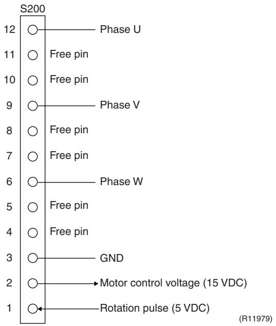
text_image
S200 12 ○ Phase U 11 ○ Free pin 10 ○ Free pin 9 ○ Phase V 8 ○ Free pin 7 ○ Free pin 6 ○ Phase W 5 ○ Free pin 4 ○ Free pin 3 ○ GND 2 ○ Motor control voltage (15 VDC) 1 ○ Rotation pulse (5 VDC) (R11979)8.3 Hall IC Check
Check No.04
FLXS, FDXS Series
- Check the connector connection.
- With the power on, operation off, and the connector connected, check the following.
*Output voltage of about 5 V between pins 1 and 3.
*Generation of 3 pulses between pins 2 and 3 when the fan motor is operating.
If NG in step 1 → Defective PCB → Replace the PCB. If NG in step 2 → Defective Hall IC → Replace the fan motor. If OK in both steps 1 and 2 → Replace the PCB.
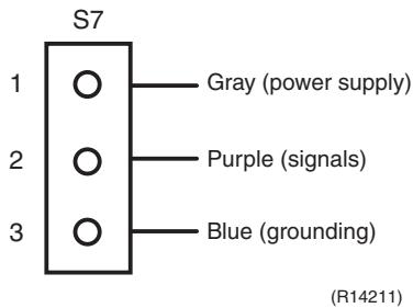
text_image
S7 1 ○ — Gray (power supply) 2 ○ — Purple (signals) 3 ○ — Blue (grounding) (R14211)8.4 Indoor Electronic Expansion Valve Coil Check
Check No.06
Conduct the followings to check the indoor electronic expansion valve coil (EV).
- Check to see if the EV connector is correctly connected to the PCB.
- Turn the power off and on again, and check to see if the EV generate latching sound.
- If the EV does not generate latching sound in the above step 2, disconnect the connector and check the continuity using a tester.
- Check the continuity between the pins 1 - 6, 2 - 6, 3 - 6, and 4 - 6. If there is no continuity between the pins, the EV coil is faulty.
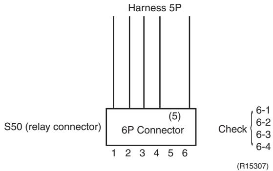
text_image
Harness 5P S50 (relay connector) (5) 6P Connector Check 1 2 3 4 5 6 6-1 6-2 6-3 6-4 (R15307)- If the continuity is confirmed in the above step 3, the PCB is faulty.

Note: Please note that the latching sound varies depending on the valve type.
8.5 Power Supply Waveform Check
Check No.11
Measure the power supply waveform between No. 1 and No. 2 on the terminal board, and check the waveform disturbance.
■ Check to see if the power supply waveform is a sine wave (Fig.1).
■ Check to see if there is waveform disturbance near the zero cross (sections circled in Fig.2)
[Fig.1]
[Fig.2]
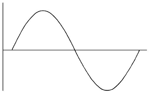
natural_image
Simple sine wave diagram with no text or labels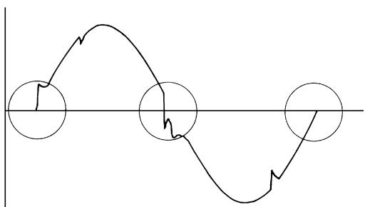
natural_image
Pure waveform diagram with three circular markers and no text or symbols(R1736)
(R1444)
8.6 Outdoor Electronic Expansion Valve Check
Check No.12
Conduct the followings to check the outdoor electronic expansion valve (EV).
- Check to see if the EV connector is correctly inserted in the PCB. Match the EV unit number and the connector number.
- Turn the power off and on again, and check to see if all the EVs generate latching sound.
- If any of the EVs does not generate latching sound in the above step 2, disconnect that connector and check the continuity using a tester.
Check the continuity between the pins 1 - 6 and 3 - 6, and between the pins 2 - 5 and 4 - 5. If there is no continuity between the pins, the EV coil is faulty.
- If no EV generates latching sound in the above step 2, the outdoor unit PCB is faulty.
- If the continuity is confirmed in the above step 3, mount a good coil (which generated latching sound) in the EV unit that did not generate latching sound, and check to see if that EV generates latching sound.
*If latching sound is generated, the outdoor unit PCB is faulty.
*If latching sound is not generated, the EV unit is faulty.

Note: Please note that the latching sound varies depending on the valve type.
If the system keeps operating with a defective outdoor electronic expansion valve, the following problem may occur.
| Valve opening position | Possible problem | Check method |
| Open | Cooling:■ Flowing noise of refrigerant in the unit which is not in operation■ Water leakage at the unit which is not in operation■ Operation half due to anti-icing function | Reset power supply and conduct cooling operation unit by unit.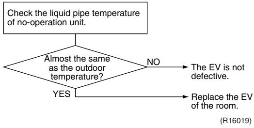 |
| Heating:■ Flowing noise of refrigerant in the unit which is not in operation■ The unit does not heat the room. | ||
| Close | Cooling:■ The problem unit does not cool the room.■ Only the problem unit is in operation, the unit starts pump down.(The low pressure of the unit becomes vacuum.)■ Abnormal discharge pipe temperature | Reset power supply and conduct cooling operation unit by unit.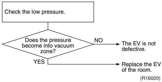 |
| Heating:■ Refrigerant shortage due to stagnation of liquid refrigerant inside the faulty indoor unit■ The unit does not heat the room.■ Abnormal discharge pipe temperature |
8.7 Four Way Valve Performance Check
Check No.13
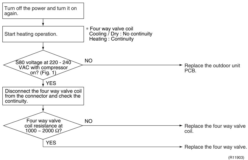
flowchart
graph TD
    A["Turn off the power and turn it on again."] --> B["Start heating operation."]
    B --> C{S80 voltage at 220 - 240 VAC with compressor on? (Fig. 1)}
    C -->|NO| D["Replace the outdoor unit PCB."]
    C -->|YES| E["Disconnect the four way valve coil from the connector and check the continuity."]
    E --> F{Four way valve coil resistance at 1000 ~ 2000 Ω?}
    F -->|NO| G["Replace the four way valve coil."]
    F -->|YES| H["Replace the four way valve."]
    G --> I["(R11903)"]
    H --> I
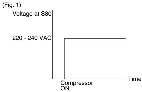
line
| Time | Voltage at S80 | | ---------- | -------------- | | Compressor ON | 220 - 240 VAC |(R11904)
8.8 Inverter Unit Refrigerant System Check
Check No.14
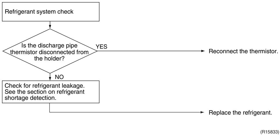
flowchart
graph TD
    A["Refrigerant system check"] --> B{Is the discharge pipe thermistor disconnected from the holder?}
    B -->|YES| C["Reconnect the thermistor."]
    B -->|NO| D["Check for refrigerant leakage. See the section on refrigerant shortage detection."]
    D --> E["Replace the refrigerant."]
8.9 “Inverter Checker” Check
Check No.15
■ Characteristics
If abnormal stop occurs due to compressor startup failure or overcurrent output when using an inverter unit, it is difficult to judge whether the stop is caused by the compressor failure or some other failure (control PCB, power module, etc.). The inverter checker makes it possible to judge the cause of trouble easily and securely. (Connect this checker as a quasi-compressor instead of the compressor and check the output of the inverter.)
■ Operation Method
Step 1
Be sure to turn the power off.
Step 2
Install the inverter checker instead of a compressor.
Note:
Make sure the charged voltage of the built-in smoothing electrolytic capacitor drops to 10 VDC or below before carrying out the service work.
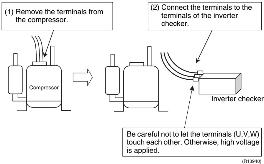
flowchart
graph TD
    A["(1) Remove the terminals from the compressor."] --> B["Compressor"]
    B --> C["(2) Connect the terminals to the terminals of the inverter checker."]
    C --> D["Inverter checker"]
    D --> E["Be careful not to let the terminals (U,V,W) touch each other. Otherwise, high voltage is applied."]
Reference:
If the terminals of the compressor are not FASTON terminals (difficult to remove the wire on the terminals), it is possible to connect wires available on site to the outdoor unit from output side of PCB. (Do not connect them to the compressor at the same time, otherwise it may result in incorrect detection.)
Step 3
Activate the power transistor test operation from the outdoor unit.
1) Press the forced operation [ON/OFF] switch for 5 seconds.
(Refer to page 405 for the position.)
→ Power transistor test operation starts.
■ Diagnose method (Diagnose according to 6 LEDs lighting status.)
(1) If all the LEDs are lit uniformly, the compressor is defective.
→ Replace the compressor.
(2) If the LEDs are not lit uniformly, check the power module.
→ Refer to Check No.22.
(3) If NG in Check No.22, replace the power module.
(Replace the main PCB. The power module is united with the main PCB.)
If OK in Check No.22, check if there is any solder cracking on the PCB.
(4) If any solder cracking is found, replace the PCB or repair the soldered section.
If there is no solder cracking, replace the PCB.

Caution
(1) When the output frequency is low, the LEDs blink slowly. As the output frequency increases, the LEDs blink quicker. (The LEDs look like they are lit.)
(2) On completion of the inverter checker diagnosis, be sure to re-crimp the FASTON terminals. Otherwise, the terminals may be burned due to loosening.
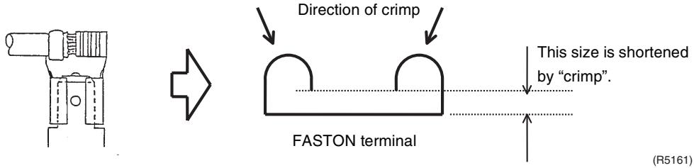
text_image
Direction of crimp FASTON terminal This size is shortened by "crimp". (R5161)8.10 Rotation Pulse Check on the Outdoor Unit PCB
Check No.16
Make sure that the voltage of 320 ± 30 V is applied.
- Set operation off and power off. Disconnect the connector S70.
- Check that the voltage between the pins 4 - 7 is 320 VDC.
- Check that the control voltage between the pins 3 - 4 is 15 VDC.
- Check that the rotation command voltage between the pins 2 - 4 is 0 \~ 15 VDC.
- Keep operation off and power off. Connect the connector S70.
- Check whether 2 pulses (0 \~ 15 VDC) are output at the pins 1 - 4 when the fan motor is rotated 1 turn by hand.
When the fuse is melted, check the outdoor fan motor for proper function.
If NG in step 2 → Defective PCB → Replace the PCB.
If NG in step 4 → Defective Hall IC → Replace the outdoor fan motor.
If OK in both steps 2 and 4 → Replace the PCB.
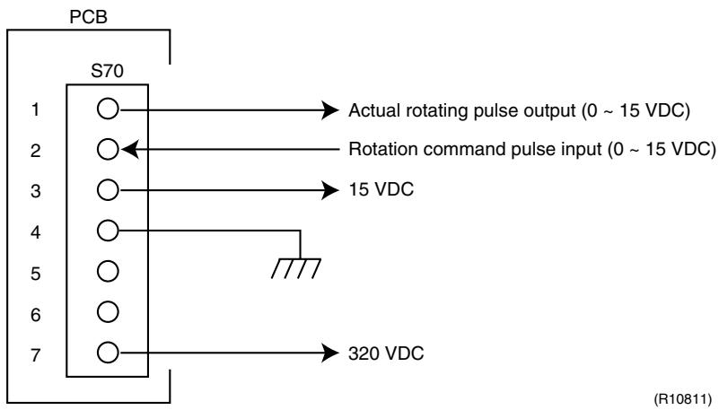
text_image
PCB S70 1 ○→ Actual rotating pulse output (0 ~ 15 VDC) 2 ○← Rotation command pulse input (0 ~ 15 VDC) 3 ○→ 15 VDC 4 ○ 5 ○ 6 ○ 7 ○→ 320 VDC (R10811)8.11 Installation Condition Check
Check No.17
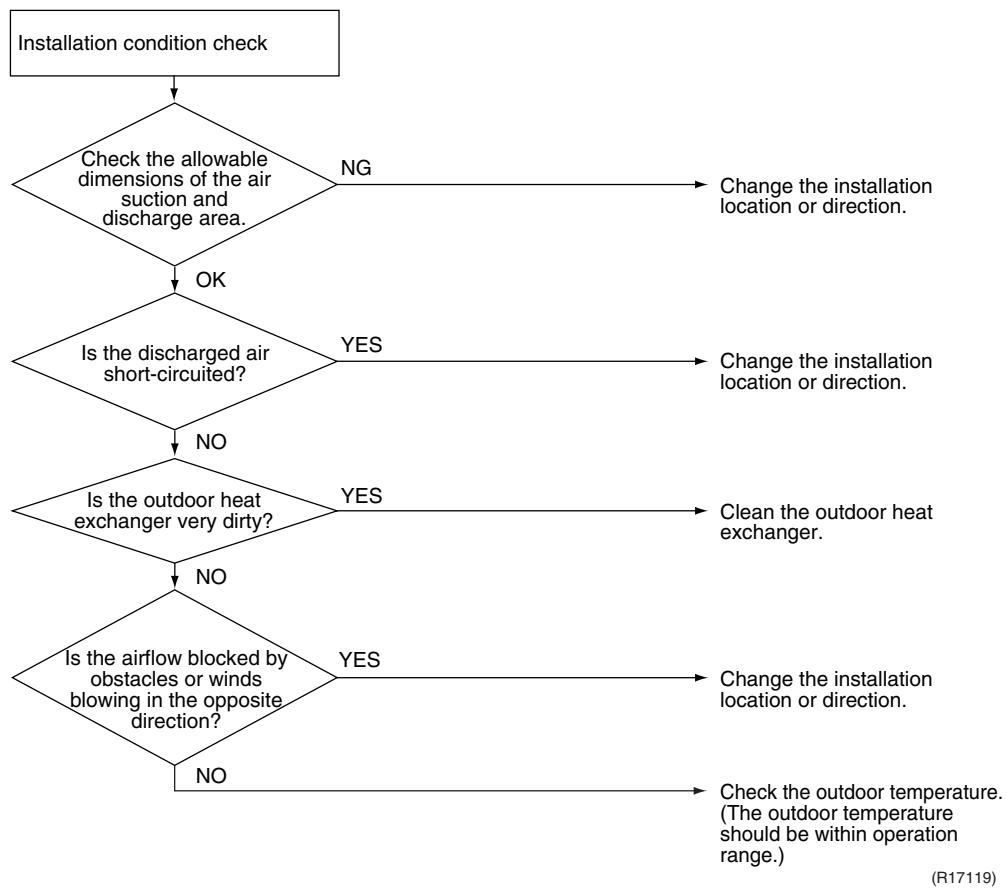
flowchart
graph TD
    A["Installation condition check"] --> B{Check the allowable dimensions of the air suction and discharge area.}
    B -->|NG| C["Change the installation location or direction."]
    B -->|OK| D{Is the discharged air short-circuited?}
    D -->|YES| E["Change the installation location or direction."]
    D -->|NO| F{Is the outdoor heat exchanger very dirty?}
    F -->|YES| G["Clean the outdoor heat exchanger."]
    F -->|NO| H{Is the airflow blocked by obstacles or winds blowing in the opposite direction?}
    H -->|YES| I["Change the installation location or direction."]
    H -->|NO| J["Check the outdoor temperature. (The outdoor temperature should be within operation range.)"]
8.12 Discharge Pressure Check
Check No.18
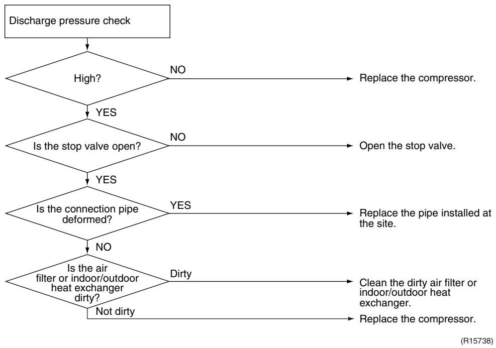
flowchart
graph TD
    A["Discharge pressure check"] --> B{High?}
    B -->|NO| C["Replace the compressor."]
    B -->|YES| D{Is the stop valve open?}
    D -->|NO| E["Open the stop valve."]
    D -->|YES| F{Is the connection pipe deformed?}
    F -->|YES| G["Replace the pipe installed at the site."]
    F -->|NO| H{Is the air filter or indoor/outdoor heat exchanger dirty?}
    H -->|Dirty| I["Clean the dirty air filter or indoor/outdoor heat exchanger."]
    H -->|Not dirty| J["Replace the compressor."]
8.13 Outdoor Fan System Check
Check No.19
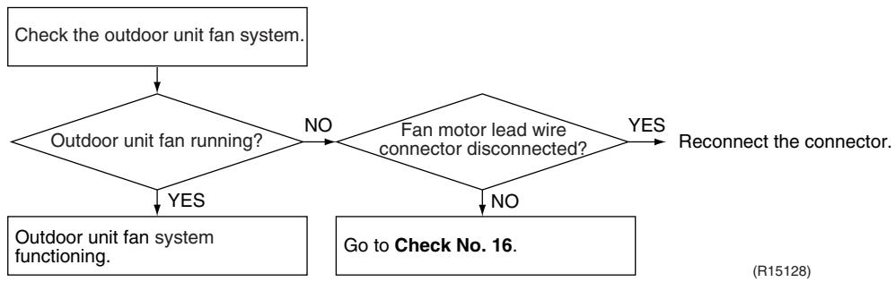
flowchart
graph TD
    A["Check the outdoor unit fan system."] --> B{Outdoor unit fan running?}
    B -->|NO| C{Fan motor lead wire connector disconnected?}
    B -->|YES| D["Outdoor unit fan system functioning."]
    C -->|YES| E["Reconnect the connector."]
    C -->|NO| F["Go to Check No. 16."]
8.14 Capacitor Voltage Check
Check No.21
Before this check, be sure to check the main circuit for short circuit.
With the circuit breaker still on, measure the voltage according to the drawing of the model in question. Be careful never to touch any live parts.
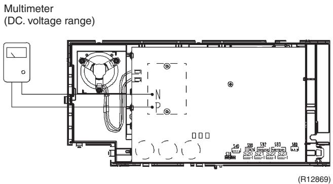
text_image
Multimeter (DC. voltage range) N P 140 320 537 533 589 (20) 520 521 522 523 (20) 520 521 522 523 (R12869)8.15 Power Module Check
Check No.22

Note: Check to make sure that the voltage between (+) and (−) of the power module (PM1) is approx. 0 V before checking.
■ Disconnect the compressor harness connector from the outdoor unit PCB. To disengage the connector, press the protrusion on the connector.
■ Follow the procedure below to measure resistance between the terminals of the power module and the terminals of the compressor with a multi-tester. Evaluate the measurement results referring to the following table.
| Negative (−) terminal of tester (positive terminal (+) for digital tester) | Power module (+) | UVW | Power module (−) | UVW |
| Positive (+) terminal of tester (negative terminal (−) for digital tester) | UVW | Power module (+) | UVW | Power module (−) |
| Resistance is OK. | several kΩ ~ several MΩ | |||
| Resistance is NG. | 0 Ω or ∞ | |||
* The illustration is for 40/50/52/58 class as representative.
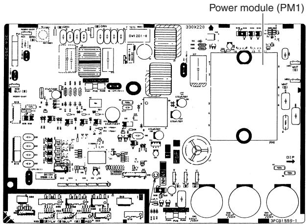
text_image
Power module (PM1) 330X220 3PG1559-1(R16074)
Part 7
Removal Procedure
1. Outdoor Unit: 40-75 Class....337
1.1 Removal of Outer Panels 337
1.2 Removal of Electrical Box 341
1.3 Removal of PCBs....349
1.4 Removal of Outdoor Fan / Fan Motor....354
1.5 Removal of Sound Blankets....356
1.6 Removal of Coils / Thermistors ....360
1.7 Removal of Distributor 363
1.8 Removal of Four Way Valve....364
1.9 Removal of Compressor....365
2. Outdoor Unit: 80/90 Class....367
2.1 Removal of Outer Panels 367
2.2 Removal of Electrical Box 382
2.3 Removal of PCBs....388
2.4 Removal of Fan Motor....392
2.5 Removal of Coils / Thermistors ....393
2.6 Removal of Sound Blankets 399
2.7 Removal of Compressor....402
1. Outdoor Unit: 40-75 Class
Note: The illustrations are for heat pump models as representative.
1.1 Removal of Outer Panels
Procedure

Warning
Be sure to wait for 10 minutes or more after turning off all power supplies before disassembling work.
| Step | Procedure | Points | |
| 1 | Appearance features |  (R5494) (R5494) (R12898) (R12898)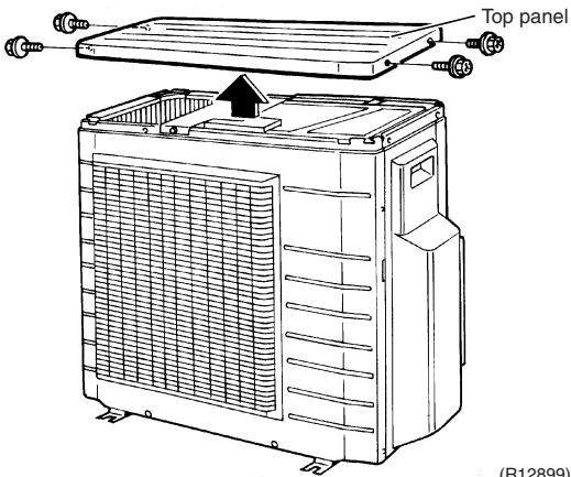 | ■ Take care not to cut your finger by the fins of the heat exchanger. |
| 2 | Remove the 4 screws (2 on both sides) of the top panel. | ||
| 3 | Remove the 6 screws of the front panel. | 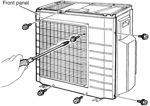 (R17165) (R17165) | |
| 4 | Remove the screw of the shield plate. | 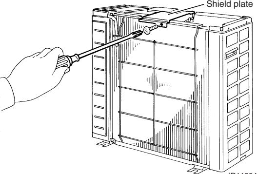 (R11204) (R11204) | |
| 5 | Slide the shield plate to the left to unfasten the hooks and remove the shield plate. | 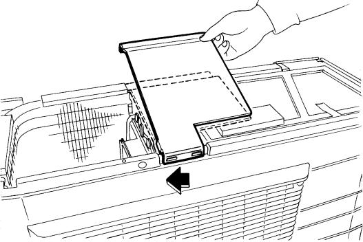 (R5499) (R5499) | |
| 6 | Unfasten the upper 2 hooks. | 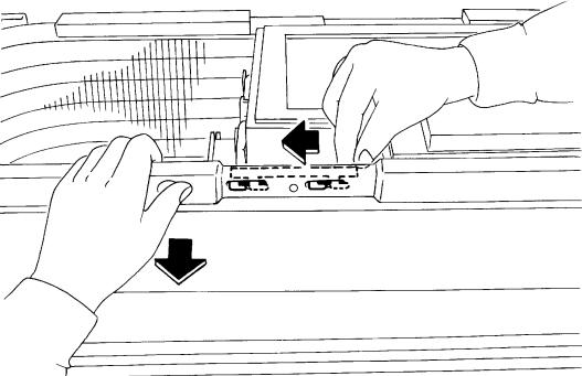 (R5500) (R5500) | ■ Align the position of hole of the upper hook to pull the front panel out. |
| 7 | Lift the front panel up to unfasten the left side hooks. | 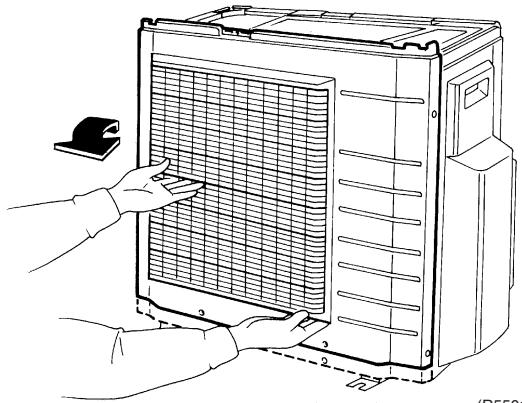 (mooi) (mooi) | The front panel has 3 hooks on the left. |
| 8 | Unfasten the right side hook and remove the front panel. | 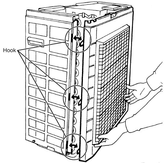 (H12901) (H12901) | |
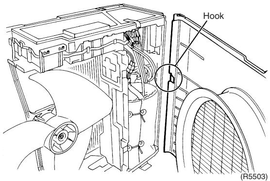 | |||
| 9 | Remove the 4 screws of the discharge grille. | 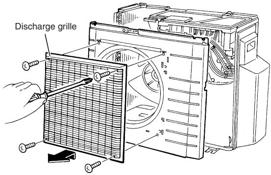 (R12902) (R12902) | |
| 10 | Remove the 2 screws of the stop valve cover. | 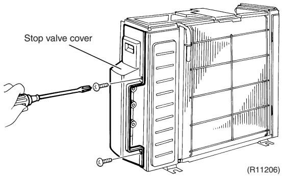 | |
| 11 | Slide the stop valve cover downward and remove it. | 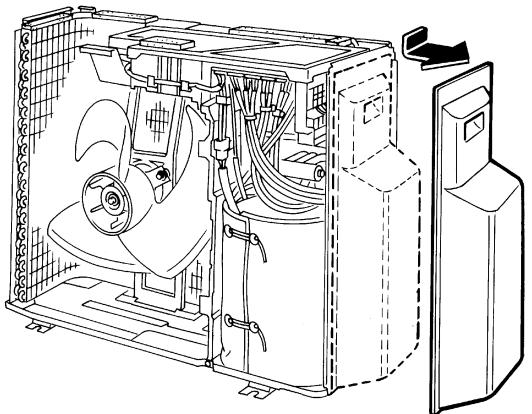 | |
| -(R5506) | ■ When reassembling, make sure to fit the 5 hooks. | ||
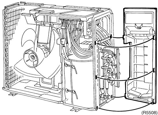 | |||
1.2 Removal of Electrical Box
Procedure

Warning
Be sure to wait for 10 minutes or more after turning off all power supplies before disassembling work.
| Step | Procedure | Points | |
| 1. Disconnect the harnesses. |  | ■ The illustrations are for 3-room models as representative, 4-room models also have D port. | |
| 1 | Layout of the connecting wires | ||
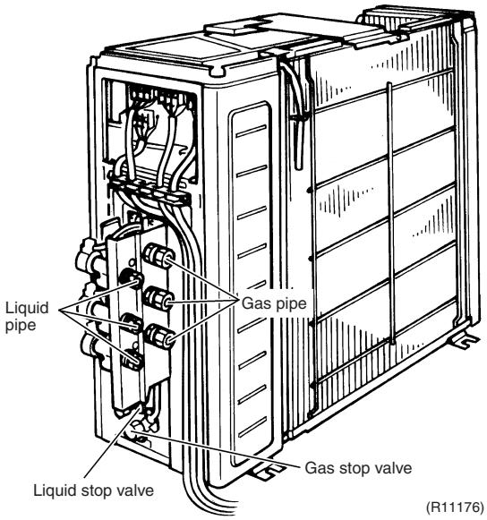 | ■ The wires are fixed to the terminal board with screws. | ||
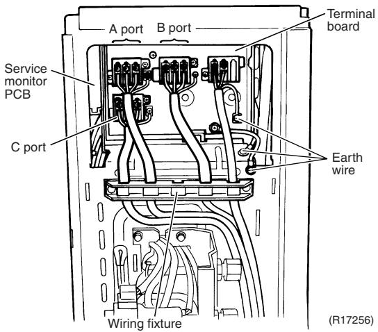 | |||
| 2 | Detach the fixing tape of the electrical box cover. | 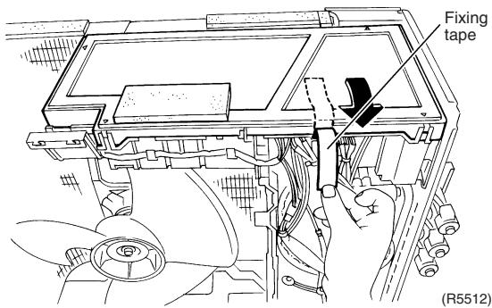 | |
| 3 | Unfasten the 4 hooks at the ▲ mark of the electrical box cover. | 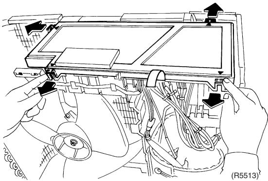 | |
| 4 | Lift the electrical box cover up and remove it. | 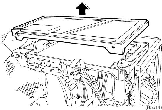 | |
| 5 | Detach the clamp and disconnect the connector for the fan motor [S70]. | 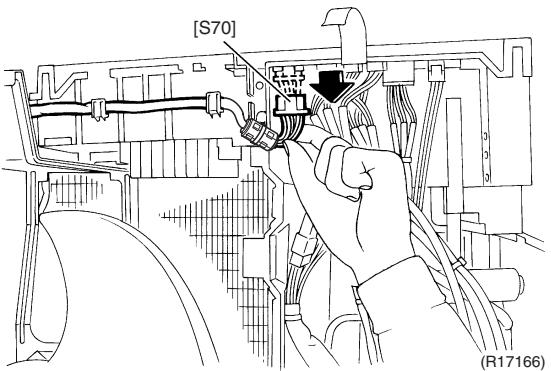 | ■ When reassembling, insert the clamp into the either hole as below.For the ferrite core of fan motor harness(R17167) |
| 6 | Release the fan motor lead wire from the hooks. | 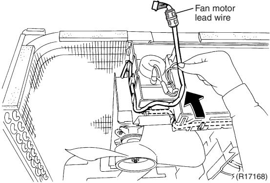 | |
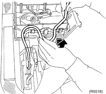 | |||
| 7 | Disconnect the connectors for the electronic expansion valve coils. | 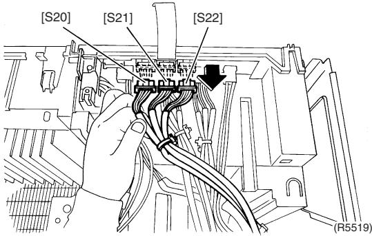 | [S20] (white) : room A[S21] (red) : room B[S22] (blue) : room C■ 4-room models also have [S23] (yellow) for room D. |
| 8 | Pull out the clamp. | 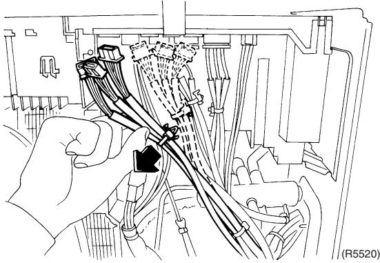 | ■ When reassembling, insert the clamp of the electronic expansion valve coil ASSY into either hole as below.○○○○○○○○○○○○○○○○○○○○○○○○○○○○○○○○○○○○○○○○○○○○○○○○○○○○○○○○○○○○○○○○○○○○○○○○○○○○○○○○○○○○○○○○○○○○○○○○○○○○ |
| 9 | Disconnect the connector for the overload protector [S40]. | 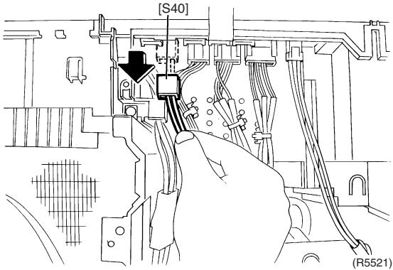 | |
| 10 | The wire harness for the compressor is attached to the partition plate by the clamp. | 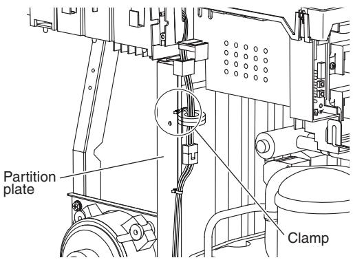 (R12904) (R12904) | |
| 11 | Pull out the clamp with pliers. | 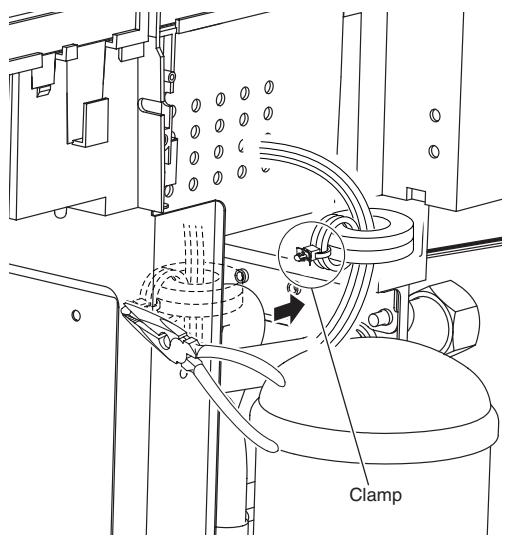 (R6423) (R6423) | |
| 12 | Disconnect the relay connector of the compressor. | 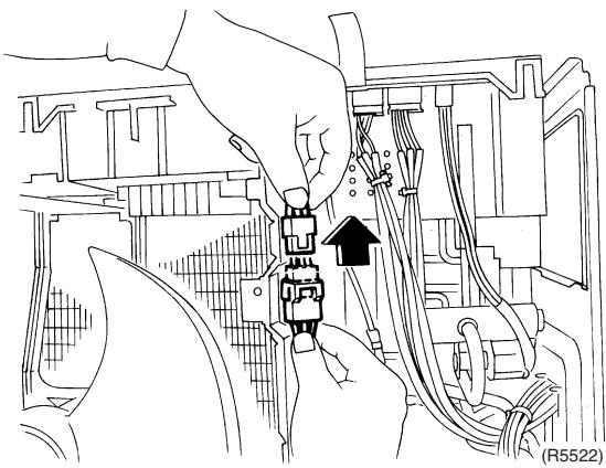 | |
| 13 | Disconnect the each connector. | 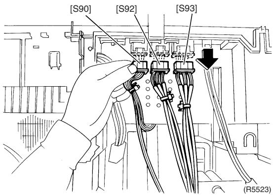 | [S90]: Thermistors[S92]: Gas pipe thermistors[S93]: Liquid pipe thermistors |
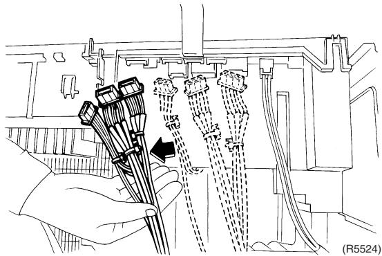 | ■ When reassembling, insert each clamp of the thermistor harnesses into the holes as below.[S92][S93][R17169] | ||
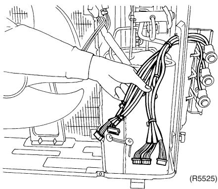 | |||
| 14 | Disconnect the connector for the four way valve coil [S80]. | 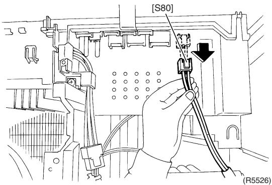 | ■ The cooling only models have no harness for [S80]. |
| 15 | The figure shows the arrangement of the wire harnesses under the electrical box. | 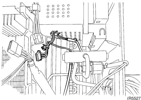 Thermistor lead wire Thermistor lead wire | ■ When reassembling, insert the clamp into the small hole.e |
| 16 | Pull out the clamp of the thermistor lead wire. | ||
| 2. Remove the electrical box. | 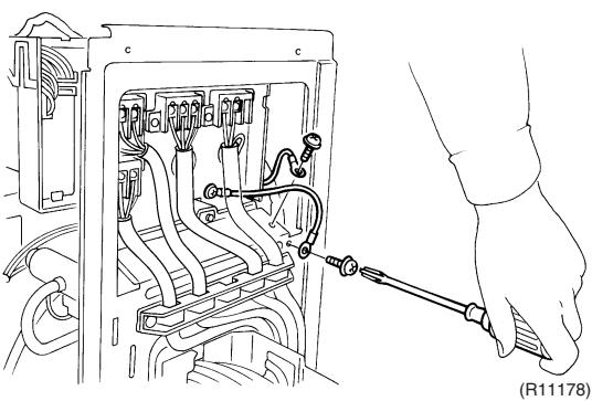 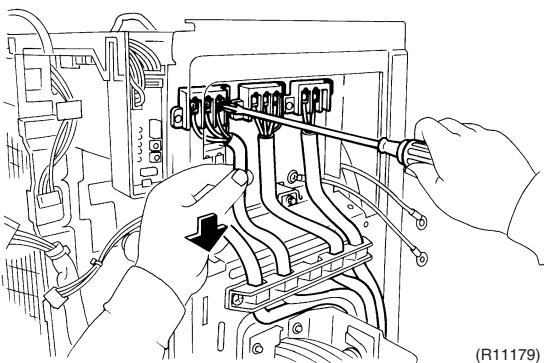 | ||
| 1 | Remove the 2 screws of the earth wires. | ||
| 2 | Remove the screws on the terminal board and disconnect all the connecting wires and power supply wire. | ||
| 3 | Remove the 2 screws and remove the wiring fixture. | 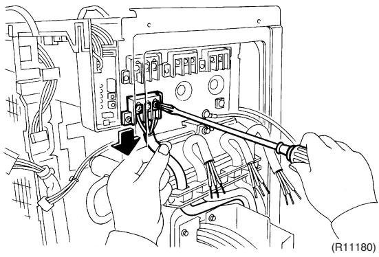 | |
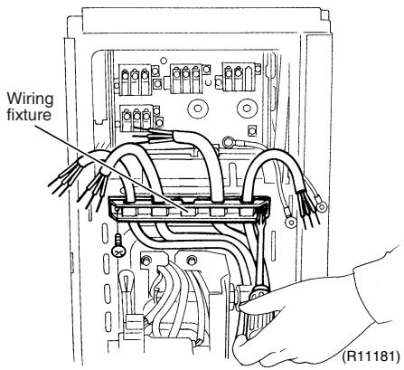 | |||
| 4 | Detach the outdoor temperature thermistor. |  | |
| 5 | Remove the screw on the right side of the electrical box. | 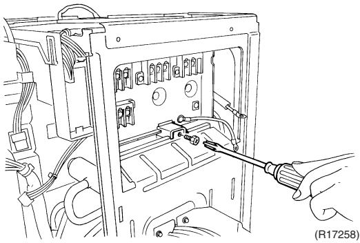 | |
| 6 | Remove the screw of the electrical box. | 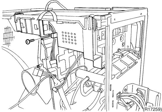 | |
| 7 | Lift up and remove the electrical box. | 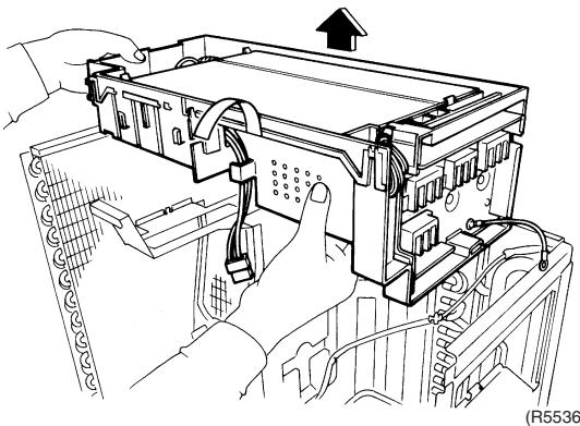 | |
1.3 Removal of PCBs
Procedure

Warning
Be sure to wait for 10 minutes or more after turning off all power supplies before disassembling work.
| Step | Procedure | Points | |
| 1. Remove the service monitor PCB. | Service monitor PCB Terminal board | ||
| 1 | External appearance | 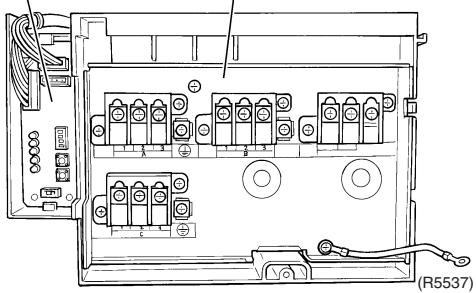 | |
| 2 | Remove the screw of the terminal board and open it. | 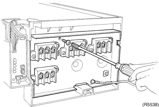 | |
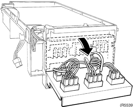 | |||
| 3 | Disconnect the connectors [S52] [S102] from the service monitor PCB. | 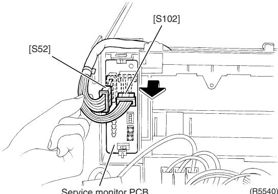 | |
| 4 | Unfasten the upper hook and pull the service monitor PCB upward to remove. | 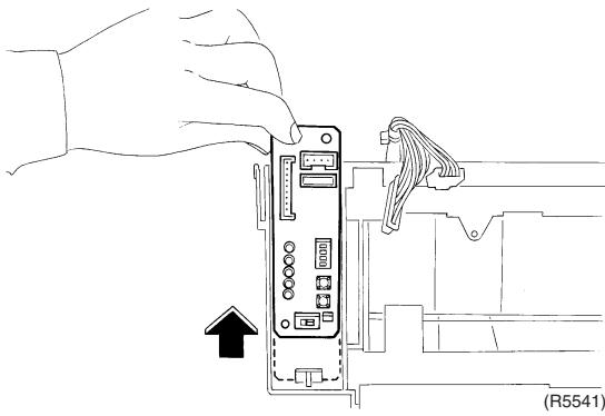 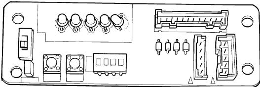 (R5542) (R5542) | Refer to page 40 for detail. |
| 2. Remove the main PCB. | 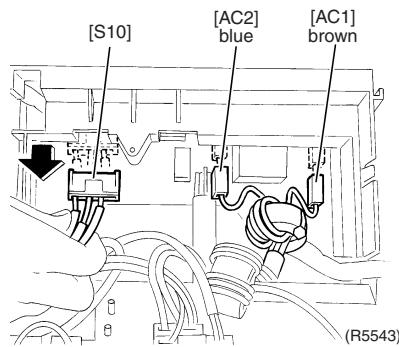 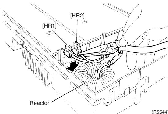 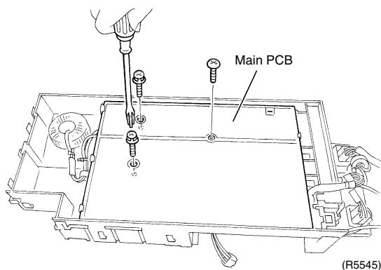 | [AC1] [AC2] : for power supply[S10] : for transmission | |
| 1 | Disconnect the connectors for the terminal board on the right side. | ||
| 2 | Disconnect the 2 connectors for the reactor on the left side. | ||
| 3 | Remove the 3 screws of the main PCB. | ||
| 4 | Unfasten the 3 hooks on the reactor side and slide the main PCB to the left. | 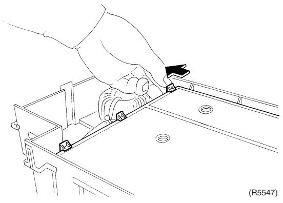 | |
| 5 | Release the relay harness for the compressor from the hook. | 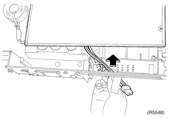 | |
| 6 | Lift up the main PCB and remove it. | 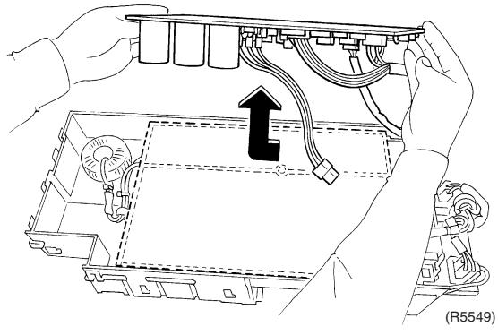 | ■ In working, be careful not to break the main PCB with the excessive force because the main PCB and the radiation fin are adhered to one another. |
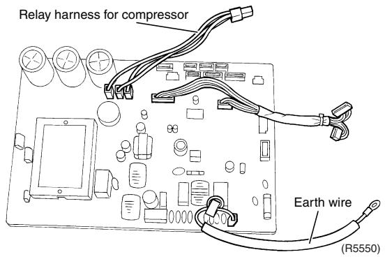 | |||
| 7 | Remove the 2 screws of the radiation fin. | 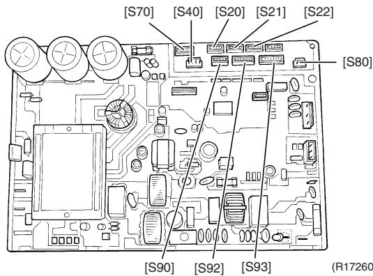 | Refer to page 39 for detail. |
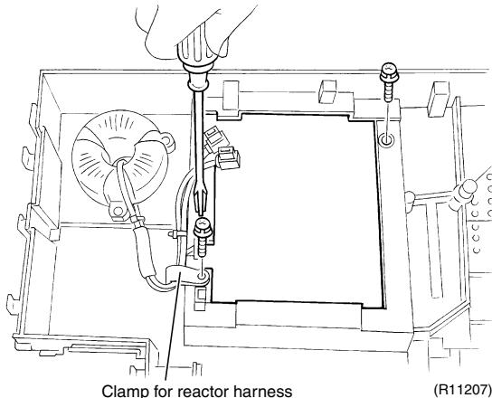 | When reassembling, make sure to use the silicon grease.Silicon grease Part No.: 1172698 | ||
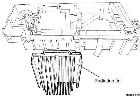 | |||
| 8 | Remove the 3 screws of the reactor. | 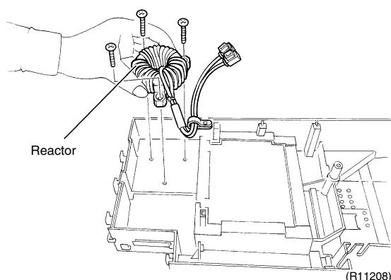 | |
| 3. Remove the terminal board. | 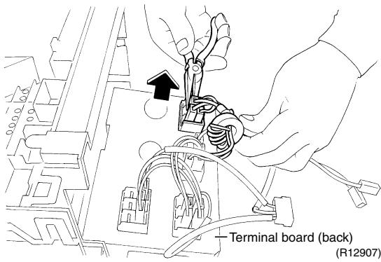 | ||
| 1 | Disconnect all the wire harnesses from the back of the terminal board. | ||
| 2 | Unfasten the hook of the electrical box and remove the terminal board. | 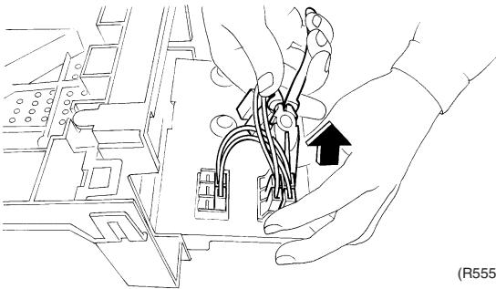 6) 6) | |
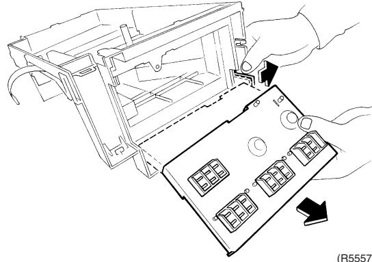 | |||
 | |||
1.4 Removal of Outdoor Fan / Fan Motor
Procedure

Warning
Be sure to wait for 10 minutes or more after turning off all power supplies before disassembling work.
| Step | Procedure | Points | |
| 1 | Remove the 2 screws of the fan motor fixing plate. | 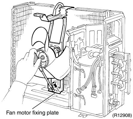 | Preparation■ Remove the outer panels and plates.■ Remove the electrical box. |
| 2 | Remove the fan motor fixing plate. | 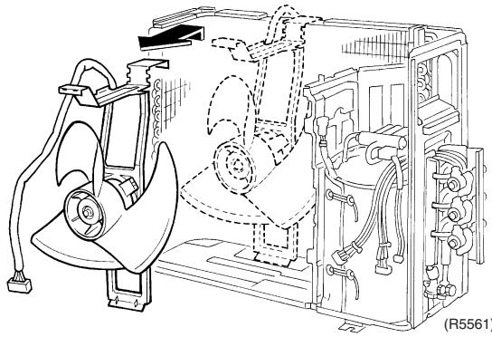 | 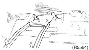 ■ When reassembling, fit the lower hooks.■ Nut size: M6 ■ When reassembling, fit the lower hooks.■ Nut size: M6 |
| 3 | Remove the nut and remove the outdoor fan. | 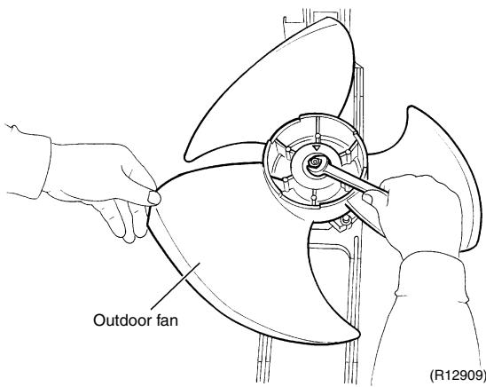 | 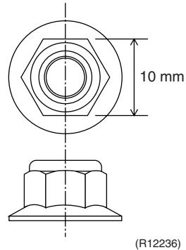 ■ When reassembling, align the ▼ mark of the outdoor fan with the D-cut section of the motor shaft. ■ When reassembling, align the ▼ mark of the outdoor fan with the D-cut section of the motor shaft. |
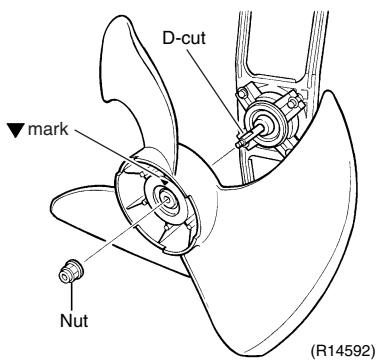 | |||
| 4 | Open the 2 hooks and release the fan motor lead wire. | 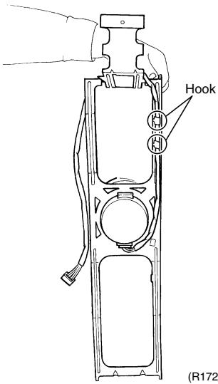 61) 61)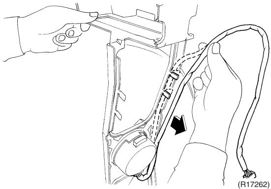 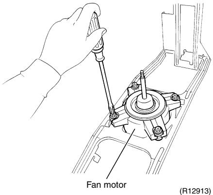 | ■ When reassembling, put the fan motor lead wire through the back of the fan motor so as not to be entangled with the outdoor fan.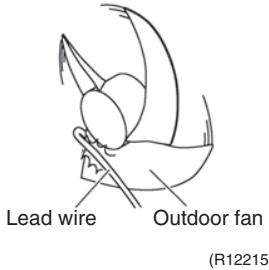 |
| 5 | Remove the 4 screws and remove the fan motor. | ||
1.5 Removal of Sound Blankets
Procedure

Warning
Be sure to wait for 10 minutes or more after turning off all power supplies before disassembling work.
| Step | Procedure | Points | |
| 1. Remove the right side panel. | 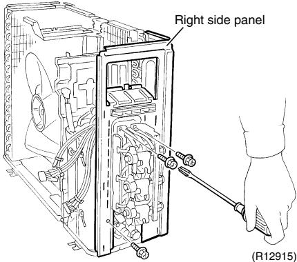 | Preparation■ Remove the outer panels and plates.■ Remove the electrical box. | |
| 1 | Remove the 3 screws of the right side panel. | ||
| 2 | Remove the 2 screws on the back. | 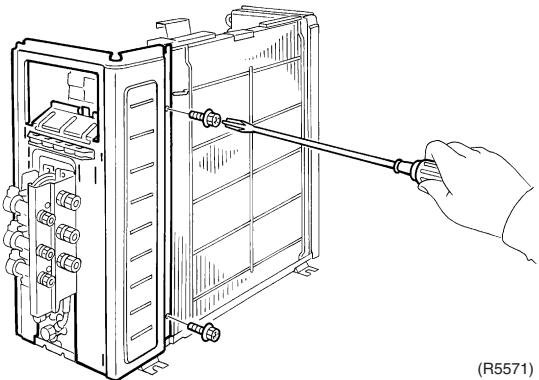 | |
| 3 | Remove the protection rubber. There is a hook on the back. | 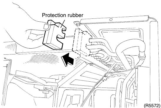 | |
| 4 | Lift up and remove the right side panel. | 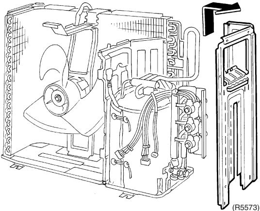 | |
| 2. Remove the partition plate. | 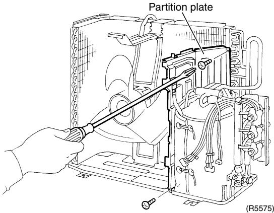 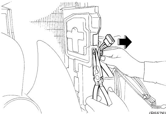 (100%) (100%) | ||
| 1 | Remove the 2 screws of the partition plate. | ||
| 2 | Detach the clamp of the relay harness for the compressor. | ||
| 3 | Lift up and remove the partition plate. | 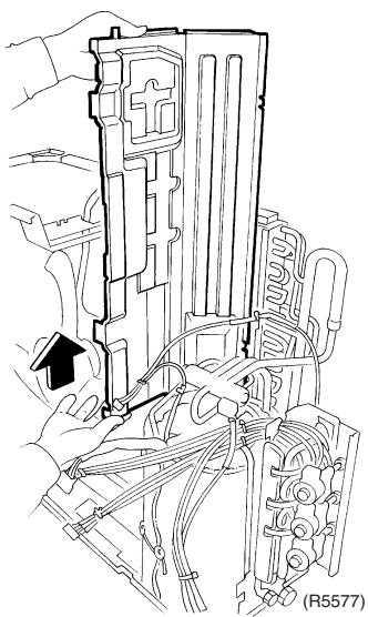 | 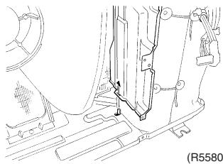 ■ When reassembling, make sure to fit the lower hook of the partition plate. ■ When reassembling, make sure to fit the lower hook of the partition plate. |
| 3. Remove the sound blankets. | 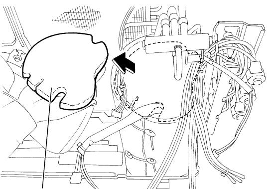 Sound blanket (top upper) (R5579) Sound blanket (top upper) (R5579)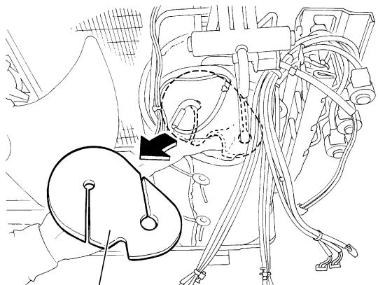 Sound blanket (top inner) (R5582) Sound blanket (top inner) (R5582) | ■ Since the piping ports on the sound blanket are torn easily, remove the blanket carefully.■ The shape of the sound blankets differs depending on the model. | |
| 1 | Remove the sound blanket (top upper). | ||
| 2 | Remove the sound blanket (top inner). | ||
| 3 | Open the sound blanket (outer) and pull it out. | 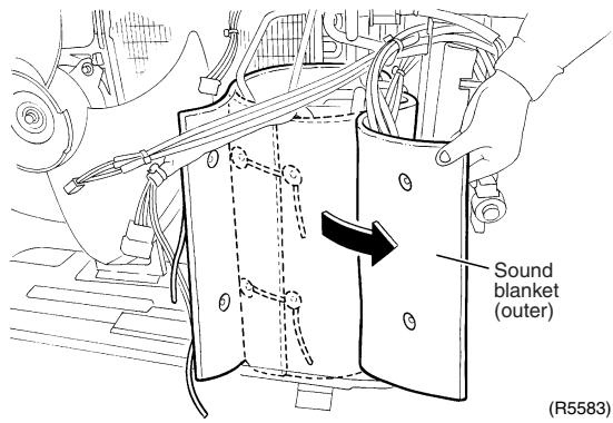 | |
| 4 | Open the sound blanket (inner) and pull it out. | 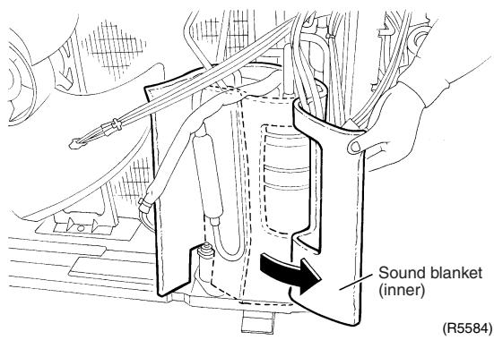 | |
1.6 Removal of Coils / Thermistors
Procedure

Warning
Be sure to wait for 10 minutes or more after turning off all power supplies before disassembling work.
| Step | Procedure | Points | |
| 1. Remove the electronic expansion valve coils. | 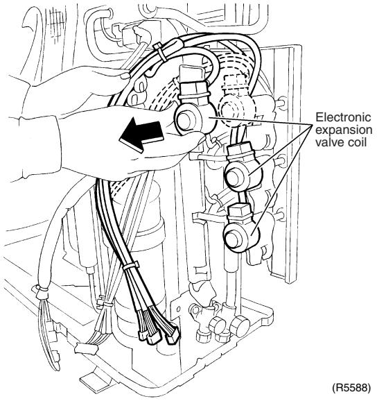 | ||
| 1 | Pull out the electronic expansion valve coils. | ||
| 2. Remove the four way valve coil. | 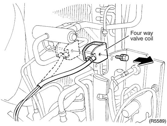 | ■ Cooling only models have no four way valve coil. | |
| 1 | Remove the screw to remove the four way valve coil. | ||
| 3. Remove the thermistors. | ■ When reassembling, meet the edge of the thermistor and the fixture. | ||
| 1 | Open the putty and remove the liquid pipe thermistors. | 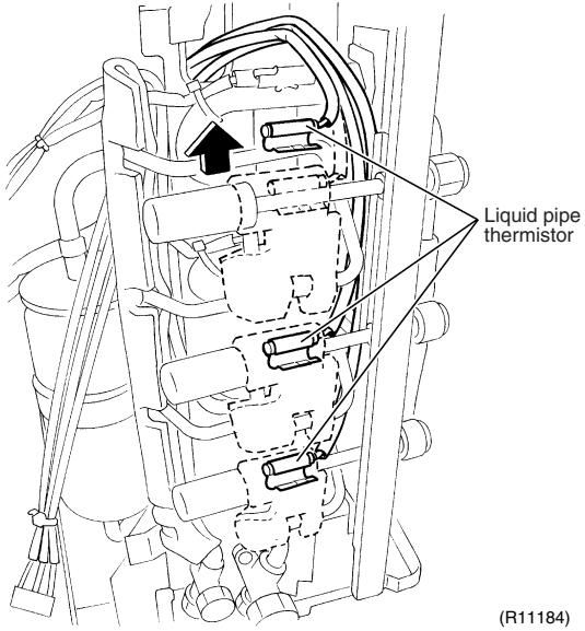 | |
| 2 | Pull out the gas pipe thermistors. | 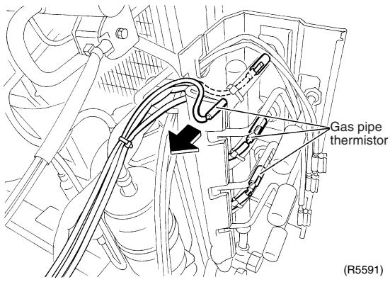 | |
| 3 | Cut the clamp.Pull out the outdoor heat exchanger thermistor. | 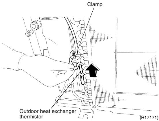 | 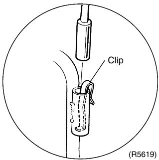 |
| ■ Be careful not to lose the clip.■ The positions of the clamp and outdoor heat exchanger thermistor differ depending on the model. | |||
| 4 | Remove the discharge pipe thermistor. | 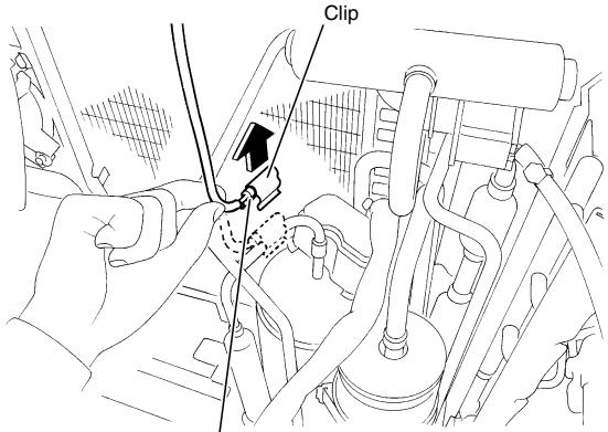 Discharge pipe thermistor (R11185) Discharge pipe thermistor (R11185) | ■ When reassembling, meet the edge of the thermistor and the fixture. |
| 5 | Remove the assembly of thermistors. | 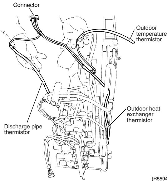 ) ) | |
1.7 Removal of Distributor
Procedure

Warning
Be sure to wait for 10 minutes or more after turning off all power supplies before disassembling work.
| Step | Procedure | Points | |
| 1 | Remove the putty. | 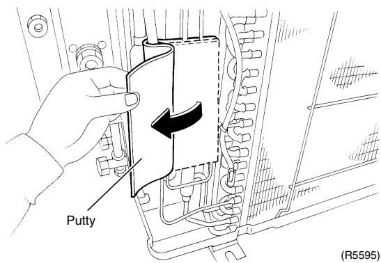 | WarningBe careful not to get yourself burnt with the pipes and other parts that are heated by the gas brazing machine.WarningIf the refrigerant gas leaks during work, ventilate the room. (If the refrigerant gas is exposed to flames, toxic gas may be generated.)CautionFrom the viewpoint of global environment protection, do not discharge the refrigerant gas in the atmosphere. Make sure to collect all the refrigerant gas.Cautions for restorationRestore the piping by non-oxidation brazing.It is required to prevent the carbonization of the oil inside the four way valve and the deterioration of the gaskets affected by heat. (Keep below 120°C.) For the sake of this, wrap the four way valve with wet cloth and provide water so that the cloth does not dry.In case of difficulty with gas brazing machineDisconnect the brazed part where is easy to disconnect and restore.Cut pipes on the main unit with a tube cutter in order to make it easy to disconnect. |
| ■ Before working, make sure that the refrigerant gas is empty in the circuit.■ Be sure to apply nitrogen replacement when heating up the brazed part. | |||
| 2 | Heat up and disconnect the brazed parts to remove the distributor. | 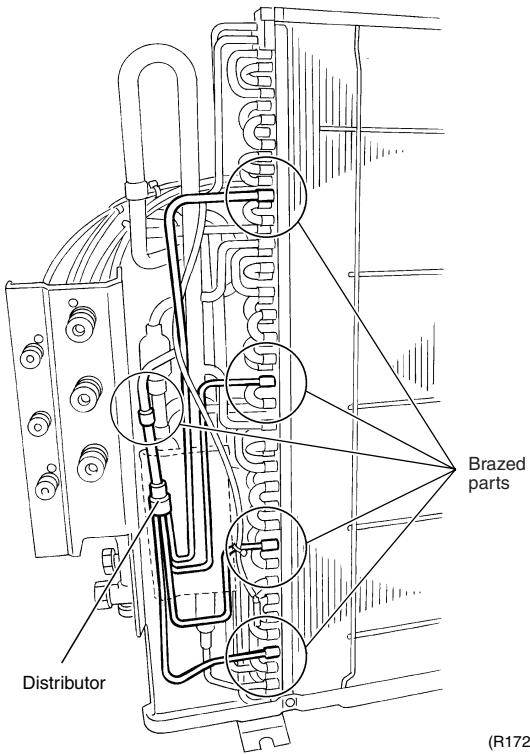 | |
| Note:■ Do not use a metal saw for cutting pipes by all means because the sawdust comes into the circuit.■ When withdrawing the pipes, be careful not to pinch them firmly with pliers. The pipes may get deformed.■ Provide a protective sheet or a steel plate so that the brazing flame cannot influence peripheries. | 63) | ||
1.8 Removal of Four Way Valve
Procedure

Warning
Be sure to wait for 10 minutes or more after turning off all power supplies before disassembling work.
| Step | Procedure | Points | |
| ■ Before working, make sure that the refrigerant gas is empty in the circuit.■ Be sure to apply nitrogen replacement when heating up the brazed part. | 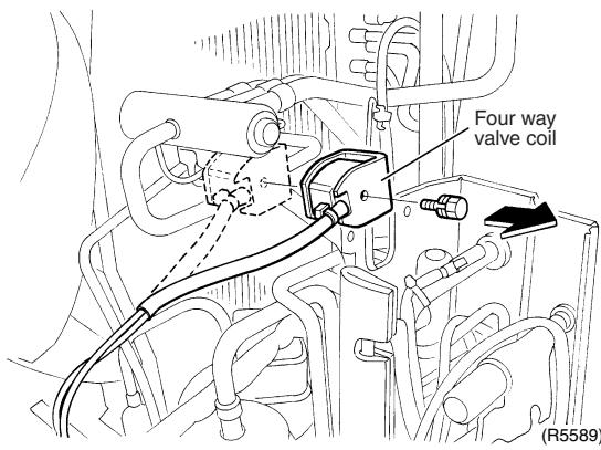 | ■ Cooling only models have no four way valve coil.⚠ WarningBe careful not to get yourself burnt with the pipes and other parts that are heated by the gas brazing machine.⚠ WarningIf the refrigerant gas leaks during work, ventilate the room. (If the refrigerant gas is exposed to flames, toxic gas may be generated.)⚠ CautionFrom the viewpoint of global environment protection, do not discharge the refrigerant gas in the atmosphere. Make sure to collect all the refrigerant gas.Cautions for restoration1. Restore the piping by non-oxidation brazing.2. It is required to prevent the carbonization of the oil inside the four way valve and the deterioration of the gaskets affected by heat. (Keep below 120°C.) For the sake of this, wrap the four way valve with wet cloth and provide water so that the cloth does not dry.In case of difficulty with gas brazing machine1. Disconnect the brazed part where is easy to disconnect and restore.2. Cut pipes on the main unit with a tube cutter in order to make it easy to disconnect. | |
| 1 | Remove the screw to remove the four way valve coil. | ||
| 2 | Heat up the 4 brazed part of the four way valve. First, disconnect the part (a). | ||
| 3 | Disconnect the part (b). | ||
| 4 | Disconnect the part (c) and (d) and remove the four way valve. | ||
| Note:■ Do not use a metal saw for cutting pipes by all means because the sawdust comes into the circuit.■ When withdrawing the pipes, be careful not to pinch them firmly with pliers. The pipes may get deformed.■ Provide a protective sheet or a steel plate so that the brazing flame cannot influence peripheries. | |||
1.9 Removal of Compressor
Procedure

Warning
Be sure to wait for 10 minutes or more after turning off all power supplies before disassembling work.
| Step | Procedure | Points | |
| 1 | Remove the terminal cover. | 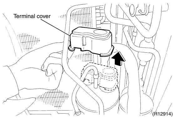 | |
| 2 | Disconnect the compressor lead wires. | 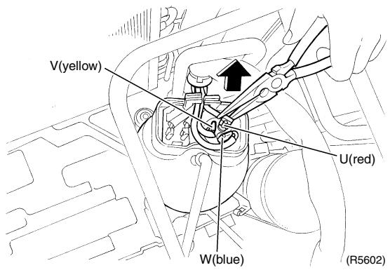 | |
| 3 | Detach the overload protector. | 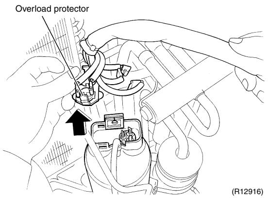 | |
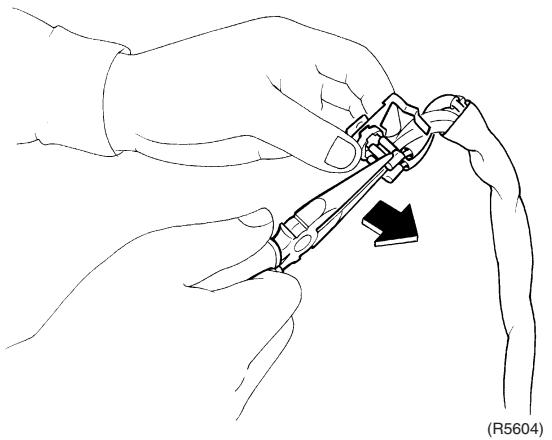 | |||
| 45 | Remove the putty.Remove the 2 nuts. | 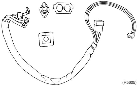 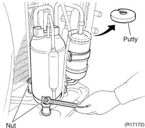 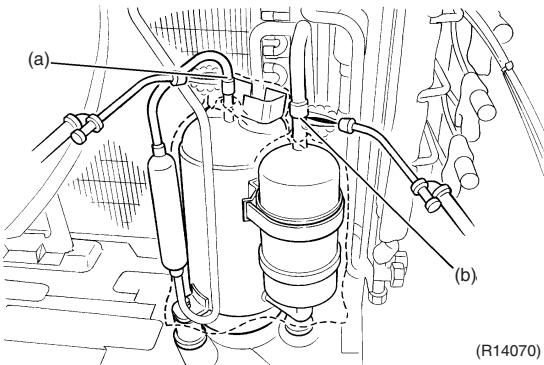 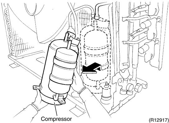 | WarningBe careful not to get yourself burnt with the pipes and other parts that are heated by the gas brazing machine.WarningIf the refrigerant gas leaks during work, ventilate the room. (If the refrigerant gas is exposed to flames, toxic gas may be generated.)WarningSince it may happen that the refrigerant oil in the compressor catches fire, prepare wet cloth so as to extinguish fire immediately.CautionFrom the viewpoint of global environment protection, do not discharge the refrigerant gas in the atmosphere. Make sure to collect all the refrigerant gas.Cautions for restorationRestore the piping by non-oxidation brazing.It is required to prevent the carbonization of the oil inside the four way valve and the deterioration of the gaskets affected by heat. (Keep below 120°C.) For the sake of this, wrap the four way valve with wet cloth and provide water so that the cloth does not dry.In case of difficulty with gas brazing machineDisconnect the brazed part where is easy to disconnect and restore.Cut pipes on the main unit with a tube cutter in order to make it easy to disconnect. |
| ■ Before working, make sure that the refrigerant gas is empty in the circuit.■ Be sure to apply nitrogen replacement when heating up the brazed part. | |||
| 678 | Heat up the brazed part of the discharge side and disconnect the part (a).Heat up the brazed part of the suction side and disconnect the part (b).Remove the compressor. | ||
| Note:■ Do not use a metal saw for cutting pipes by all means because the sawdust comes into the circuit.■ When withdrawing the pipes, be careful not to pinch them firmly with pliers. The pipes may get deformed.■ Provide a protective sheet or a steel plate so that the brazing flame cannot influence peripheries.■ Be careful so as not to burn the compressor terminals, the name plate, the heat exchanger fin. | |||
2. Outdoor Unit: 80/90 Class
Note: The illustrations are for heat pump models as representative.
2.1 Removal of Outer Panels
Procedure

Warning
Be sure to wait for 10 minutes or more after turning off all power supplies before disassembling work.
| Step | Procedure | Points | |
| Appearance features | 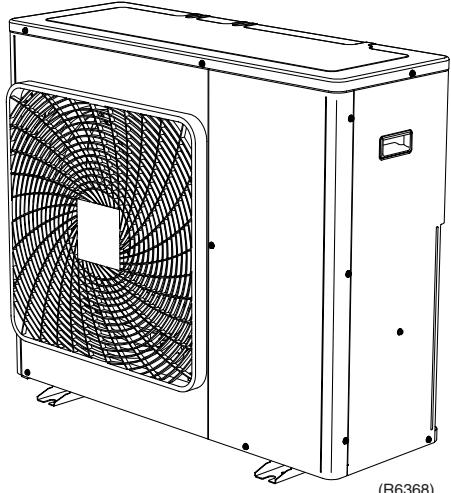 | ||
| 1. Remove the suction grille. | Rear side | ■ The hooks are secured in the clearances of the outdoor heat exchanger fins. | |
| 1 | Unfasten the 2 hooks at the bottom first. | 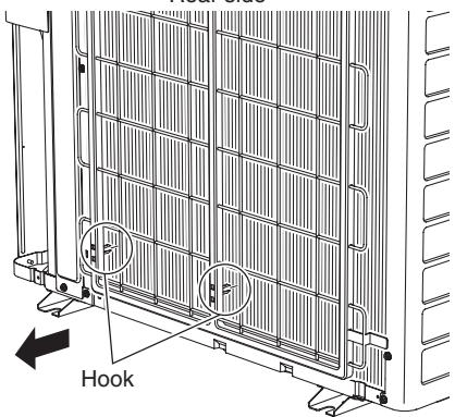 Suction grille (R14612) Suction grille (R14612)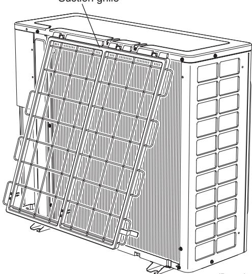 (H63/0) (H63/0) | |
| 2 | Slide the suction grille downward to unfasten the 3 top hooks. | 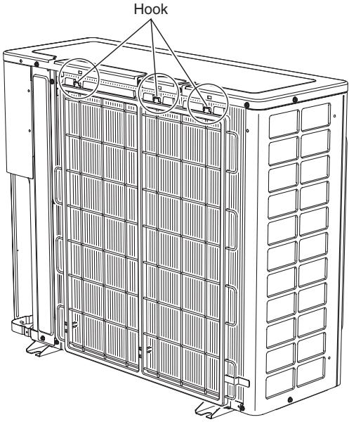 (R14613) (R14613) | |
| 3 | Remove the suction grille. | 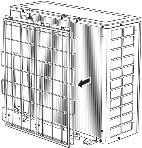 (R6372) (R6372) | |
| 2. Remove the top panel. | 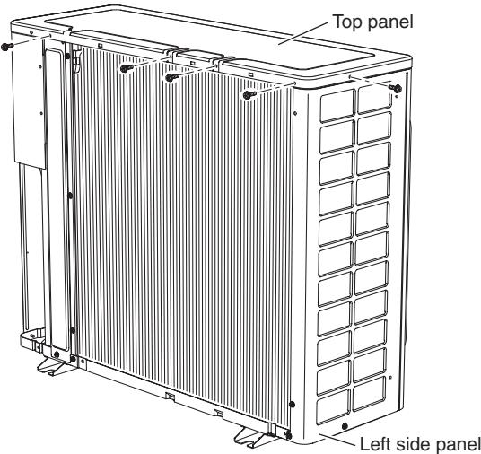 (R6373) (R6373) | ||
| 1 | Remove the 4 screws on the back and the screw on the left side panel. | ||
| 2 | Remove the 2 screws on the front and the screw on the right side panel. | 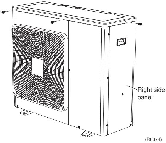 | |
| 3 | Lift the top panel and remove it. | 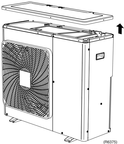 | |
| 3. Remove the right side panel. | 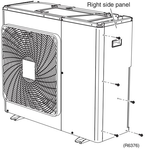 | ||
| 1 | Remove the 5 screws. | ||
| 2 | Slide the right side panel downward to unfasten the 2 hooks on the back side. | 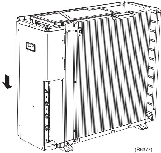 | |
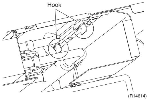 | |||
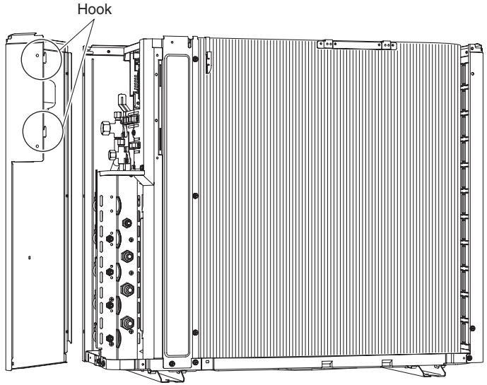 | |||
| (R14615) | |||
| 3 | Remove the right side panel. | 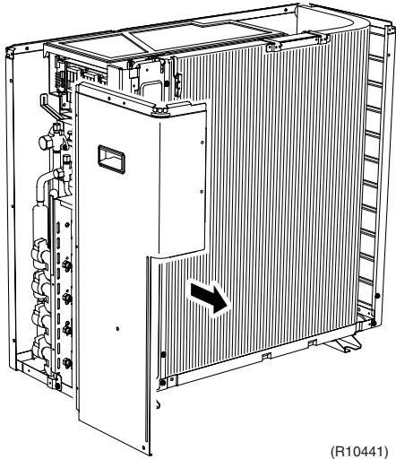 | |
| 4. Remove the front panel (2). | 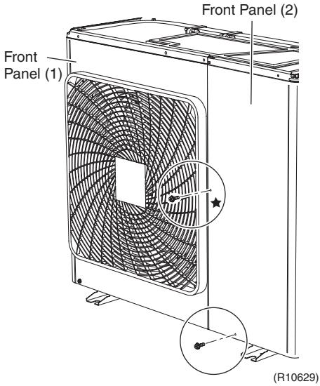 | ★ This screw is M5 × 16 | |
| 1 | Remove the 2 screws. | ||
| 2 | Slide the front panel (2) downward to unfasten the hook. | 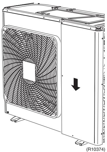 | |
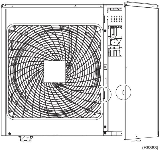 | |||
| 3 | Remove the front panel (2). | 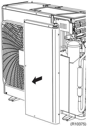 | |
| 5. Remove the front panel (1). | 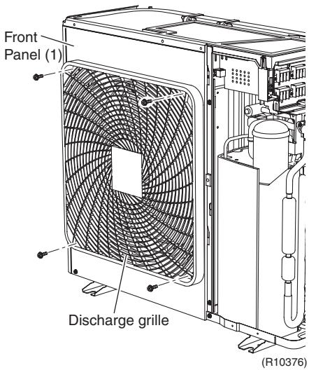 | ■ Remove the discharge grille and outdoor fan first to remove the front panel (1). | |
| 1 | Remove the 4 screws on the discharge grille. | ||
| 2 | Pull the bottom of the discharge grille. | 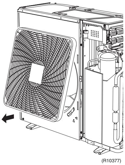 | |
| 3 | Slide the discharge grille downward to unfasten the 2 hooks at the top. | 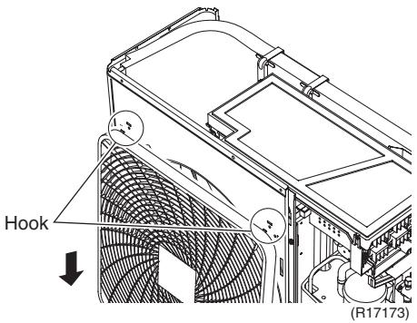 | |
| 4 | Remove the discharge grille. | 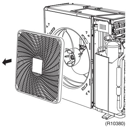 | |
| 5 | Remove the nut and remove the outdoor fan. | 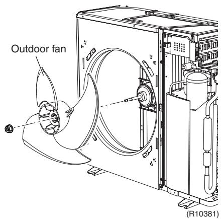 | ■ Nut size : M8 ■ When reassembling, align ▼ mark of the outdoor fan with D-cut section of the motor shaft. ■ When reassembling, align ▼ mark of the outdoor fan with D-cut section of the motor shaft. |
| 6 | Remove the 2 screws on the partition plate (1). | -C5ZD] | |
| 7 | Remove the screw at the bottom left of the front panel (1). | 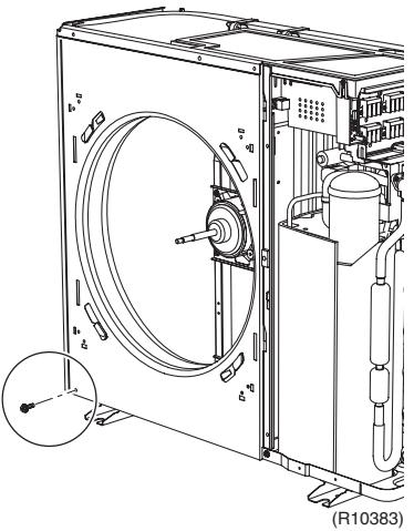 | |
| 8 | Remove the screw at the bottom of the left side. | 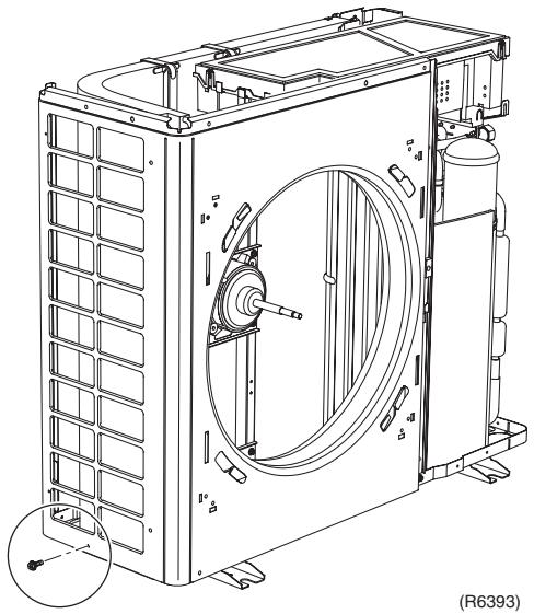 | |
| 9 | Remove the screw at the bottom of the back side. | 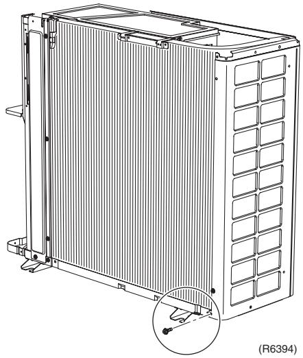 | |
| 10 | The front panel (1) has a hook. Lift the front panel (1). | 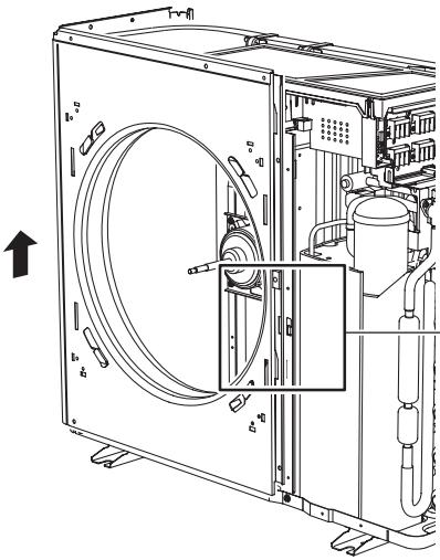 —— —— 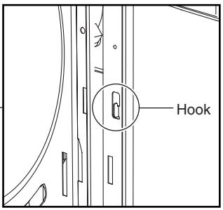 | |
| 11 | Remove the front panel (1). | 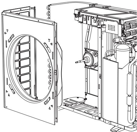 | |
| (R10385) | |||
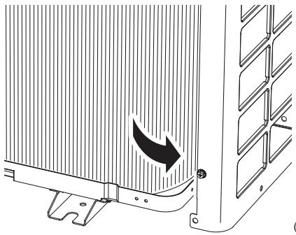 | ■ Be sure to detach the front panel (1) carefully so as not to deform it. | ||
| R6396) | |||
| 6. Remove the rear panel. | 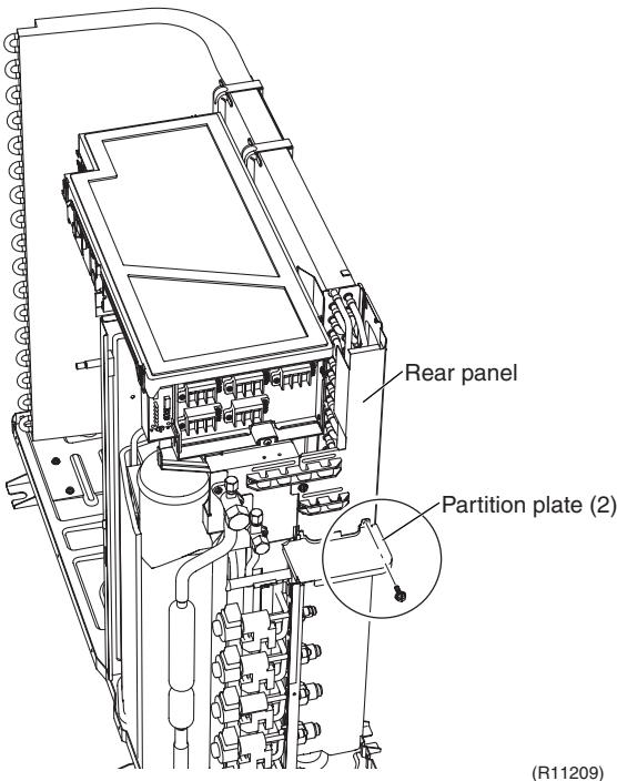 | ||
| 1 | Remove the screw on the partition plate (2). | ||
| 2 | Slide the partition plate (2) to the left and remove it. | 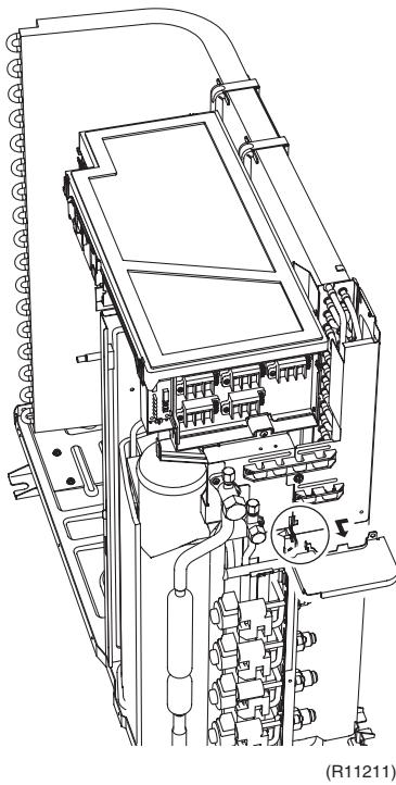 | |
| 3 | Remove the 5 screws on the wire fixing plate (upper). | 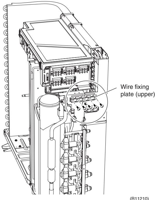 | |
| 4 | Remove the wire fixing plate (upper). | 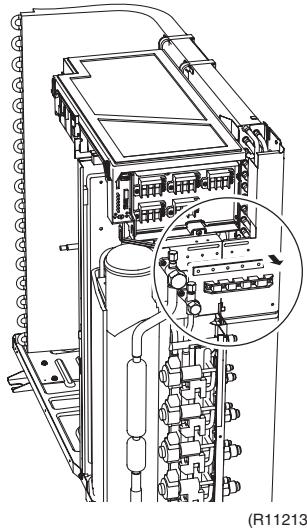 | |
| 5 | Remove the 3 screws on the wire fixing plate (lower). | 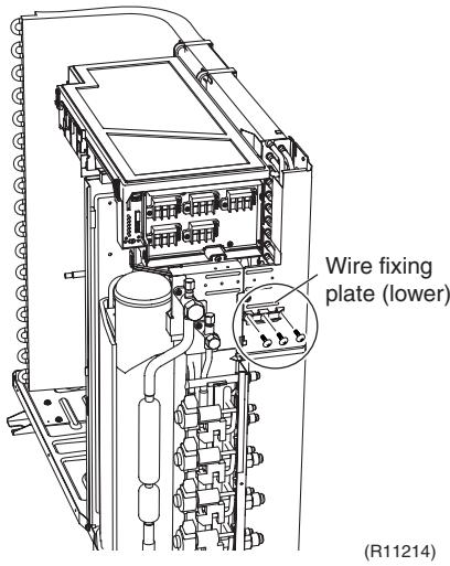 | |
| 6 | Remove the wire fixing plate (lower). | 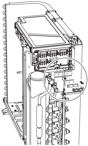 | |
| 7 | Pull out the holder of the outdoor temperature thermistor. | (R11215) | ■ The holder is secured in the clearances of the outdoor heat exchanger fins. |
| 8 | Release the thermistor wire from the groove | 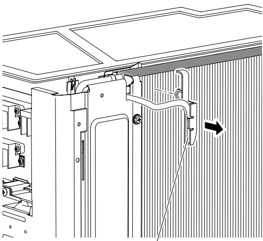 Outdoor temperature thermistor (R10388) Outdoor temperature thermistor (R10388) | |
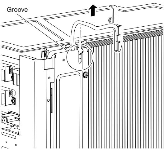 | |||
| (R10389) | |||
| 9 | Remove the 3 screws on the rear panel. | 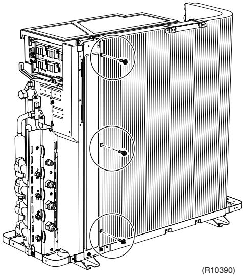 | |
| 10 | Remove the screw on the bottom frame. | 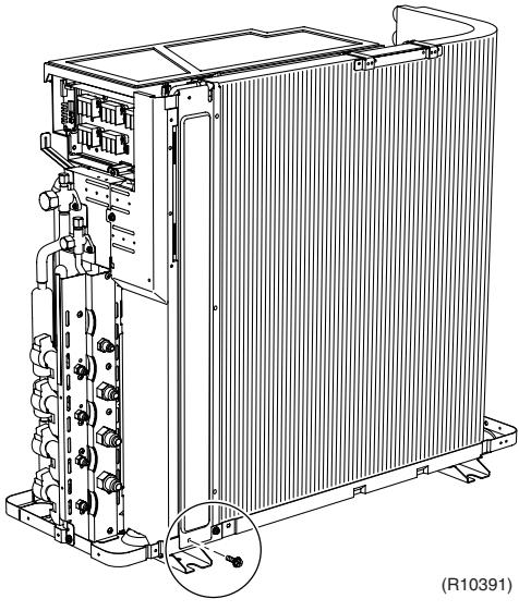 | |
| 11 | Remove the screw on the stop valve mounting plate. | 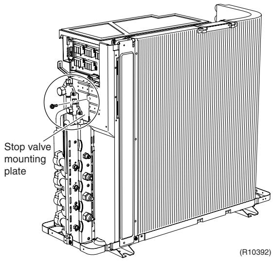 | |
| 12 | Lift the rear panel upward to unfasten the 2 hooks. | 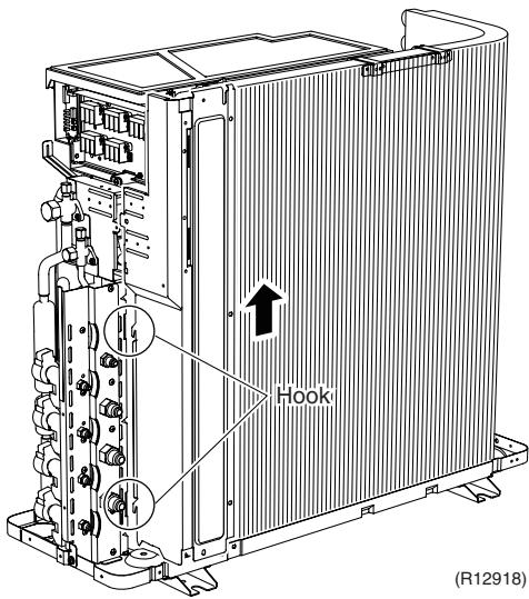 | |
| 13 | Remove the rear panel. | 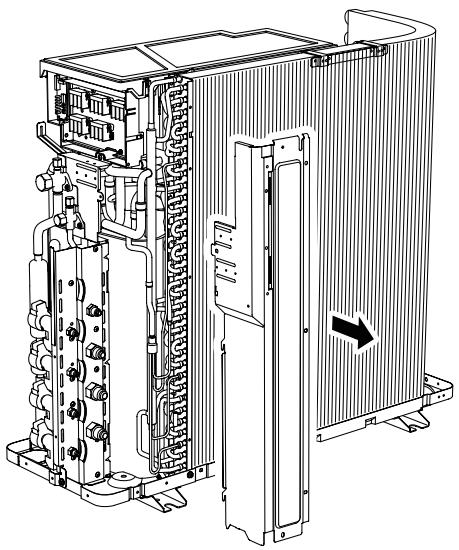 (R10394) (R10394) | |
2.2 Removal of Electrical Box
Procedure

Warning
Be sure to wait for 10 minutes or more after turning off all power supplies before disassembling work.
| Step | Procedure | Points | |
| 1 | Remove the 2 screws to detach the earth wires. |  | |
| 2 | Disconnect the connector for the fan motor [S70]. | 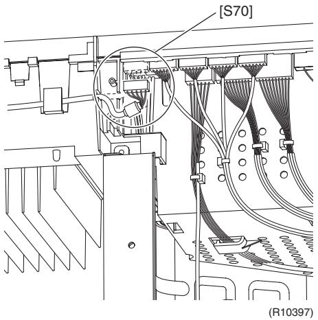 | |
| 3 | Release the fan motor lead wire. | Fan motor lead wire | ★: When reassembling, do not use these 2 hooks. |
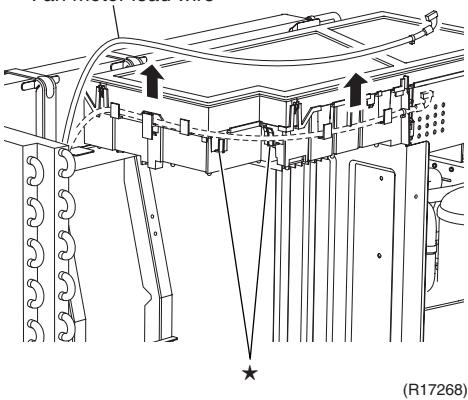 | |||
| 4 | Disconnect the connector for the four way valve coil [S80]. | 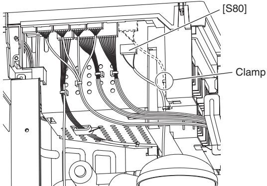 (R11187) (R11187) | ■ Pull out the clamp.■ The cooling only model has no harness for [S80]. |
| 5 | Disconnect the connectors for the electronic expansion valve coil.[S20] (white): room A[S21] (red): room B[S22] (blue): room C[S23] (yellow): room D | 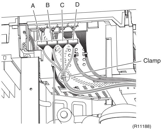 | ■ Pull out the clamp.■ 5-room models also has [S24] (green) for room E.■ When reassembling, insert each clamp into the small hole. |
| 6 | Disconnect the connector for the liquid pipe thermistor [S93]. | 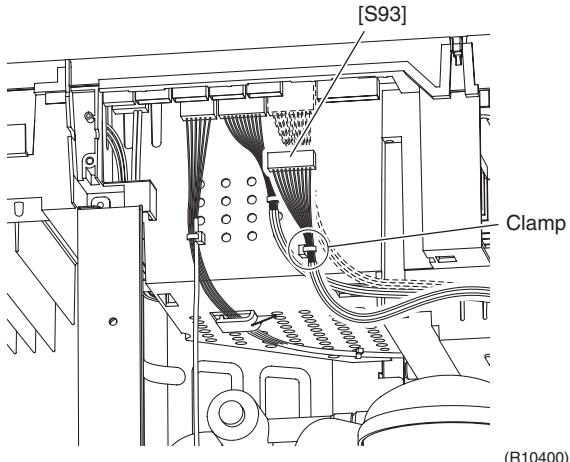 | 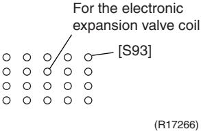 ■ Pull out the clamp. ■ Pull out the clamp. |
| 7 | Disconnect the connector for the gas pipe thermistor [S92]. | 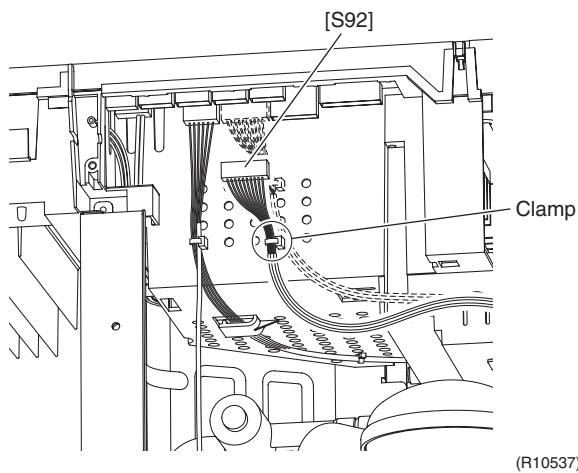 | ■ Pull out the clamp.■ When reassembling, insert the clamp into the small hole.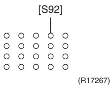 |
| 8 | Disconnect the connector for the thermistors [S90]. | 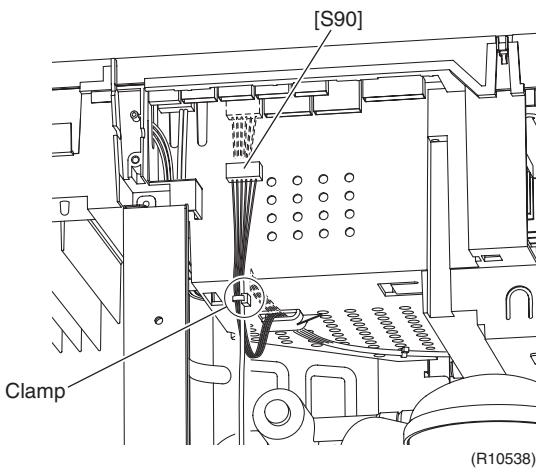 | ■ Pull out the clamp.■ When reassembling, insert the clamp of the thermistor ASSY into the hole as below.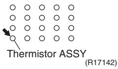 |
| 9 | The wire harness of the thermistor is hooked under the electrical box. Unhook it and pull out the clamp. | 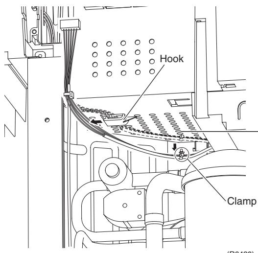 —— ——  (MD42U) (MD42U) | ■ When reassembling, insert the clamp into the small hole. |
| 10 | Disconnect the connector for the overload protector [S40]. | 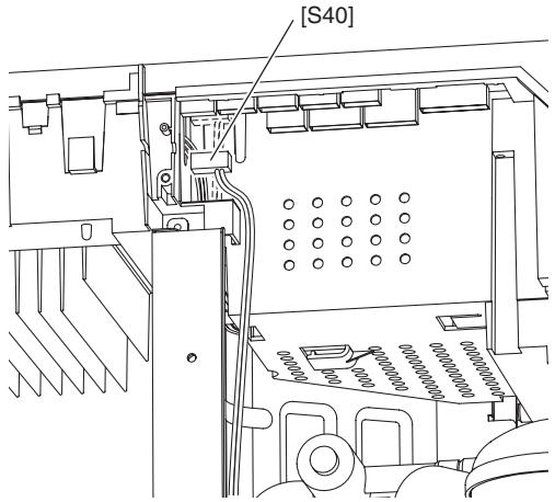 | |
| 11 | The wire harness for the compressor is attached to the partition plate (1) by the clamp. | (R10539) | |
| 12 | Pull out the clamp with pliers. | 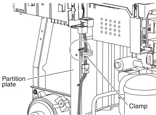 | |
| (R12904) | |||
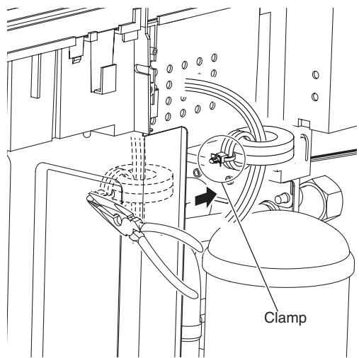 | |||
| (R6423) | |||
| 13 | Disconnect the relay connector of the compressor. | 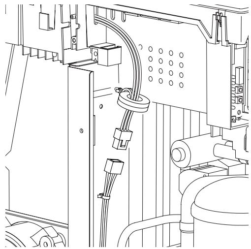 (R6469) (R6469) | |
| 14 | Remove the screw on the stop valve mounting plate. | 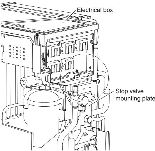 (R10395) (R10395) | |
| 15 | Remove the screw on the partition plate (1). | 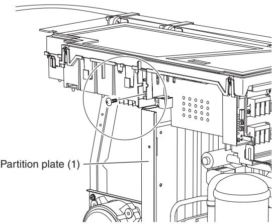 (R6411) (R6411) | |
| 16 | Slide the electrical box leftward to unfasten the hook on the right side of the electrical box. | 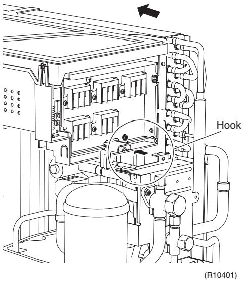 | |
| 17 | Lift up the electrical box and remove it. | 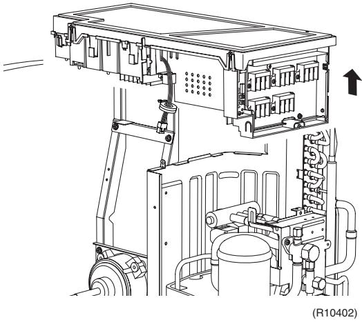 | |
2.3 Removal of PCBs
Procedure

Warning
Be sure to wait for 10 minutes or more after turning off all power supplies before disassembling work.
| Step | Procedure | Points | |
| 1. Remove the main PCB. | 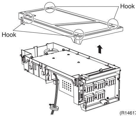 | ■ Release the 4 hooks. The hooks are marked with ▼.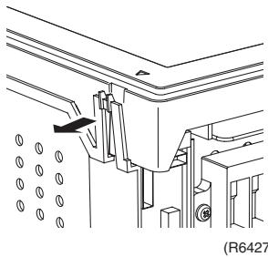 | |
| 1 | Remove the cover of the electrical box. | ||
| 2 | Remove the 3 screws. | 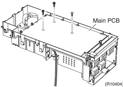 | ) |
| 3 | Unfasten the 4 hooks. | 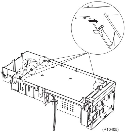 | |
| 4 | Lift up the main PCB. | 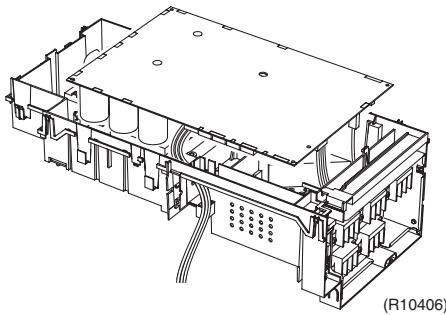 | |
| 5 | Disconnect the connectors. | U(red) V(yellow) W(blue) [S51] [S101] | [S51] [S101] : service monitor PCB[S10] : terminal board (transmission)[HR1] [HR2] : reactor[AC1] [AC2] : terminal board (power supply)[U] [V] [W] : compressorRefer to page 40 for detail. |
| 6 | Remove the main PCB. | 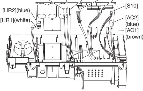 (R10407) (R10407)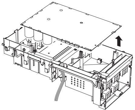 (R10408) (R10408) | |
| 2. Remove the reactor. | 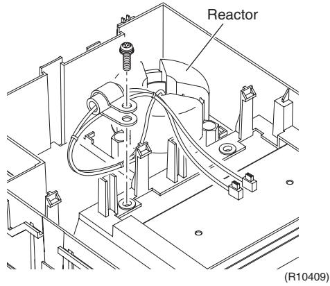 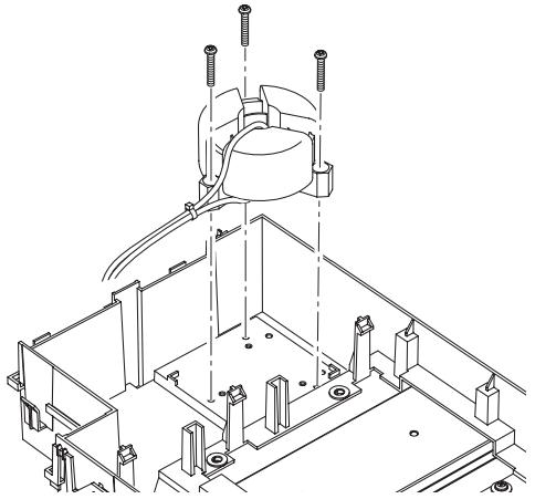 (R6434) (R6434) | ||
| 1 | Remove the screw. | ||
| 2 | Remove the 3 screws and lift the reactor upward to remove it. | ||
| 3. Remove the service monitor PCB. |  (R10410) (R10410) | ||
| 1 | Disconnect the connectors [S52] [S102] from the service monitor PCB. | ||
| 2 | Slightly lift the top hook to detach. | 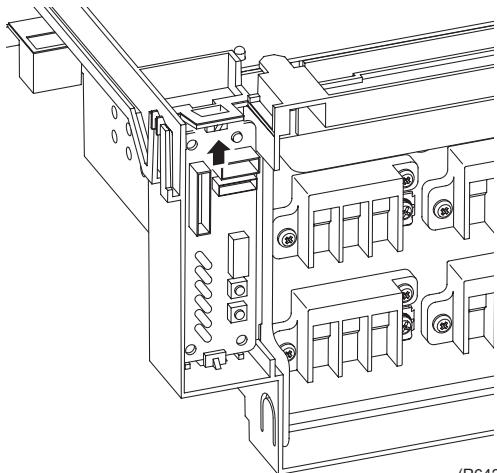 (no436) (no436) | |
| 3 | Unfasten the bottom hook and remove the service monitor PCB. | 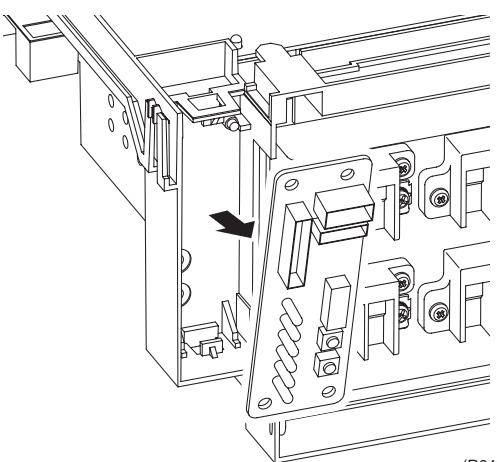 (Ho437) (Ho437) | Refer to page 40 for detail. |
| 4. Remove the terminal board. | 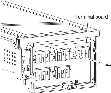 (R10411) (R10411) | ||
| 1 | Remove the screw. | ||
| 2 | Unfasten the hook. | 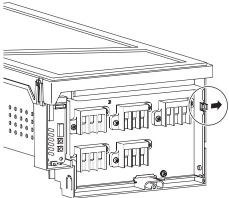 (R10412) (R10412) | |
| 3 | Remove the terminal board. | 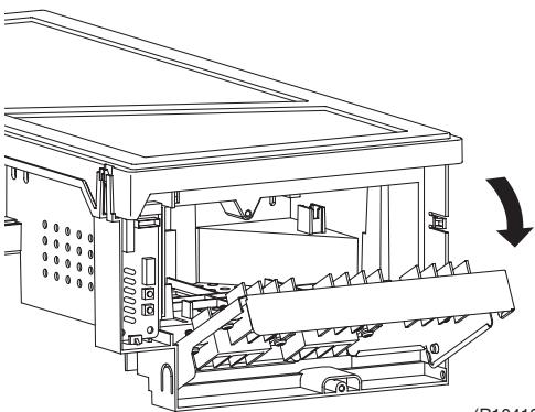 (R10413) (R10413) | |
2.4 Removal of Fan Motor
Procedure

Warning
Be sure to wait for 10 minutes or more after turning off all power supplies before disassembling work.
| Step | Procedure | Points | |
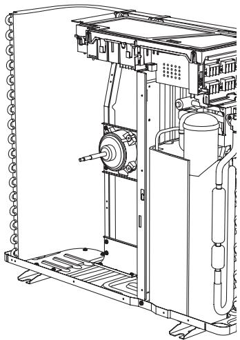 | |||
| 1 | Remove the 2 lower screws of the fan motor. | (R10414) | ■ Be sure to remove the lower screws first. If the upper screws are removed first, the fan motor may tilt or fall because the center of its gravity is toward the front. It may cause injuries. |
| 2 | Remove the 2 upper screws. | 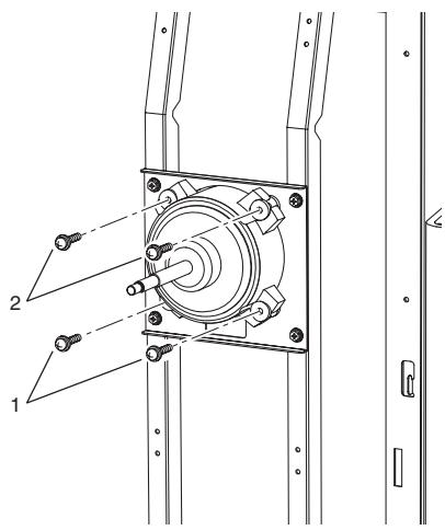 | |
| 3 | Remove the fan motor. | (R6442) | ■ When reassembling, be sure to place the wire harness lower. |
(DA23) 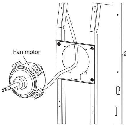 | [R10542) | ||
| (R6444) | |||
2.5 Removal of Coils / Thermistors
Procedure

Warning
Be sure to wait for 10 minutes or more after turning off all power supplies before disassembling work.
| Step | Procedure | Points | |
| 1. Remove the electronic expansion valve coils. | 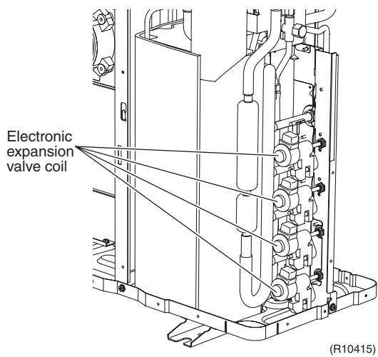 | ||
| 1 | Pull out the electronic expansion valve coils. | ||
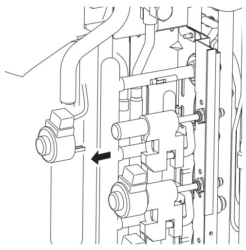 (R6446) (R6446) | |||
| 2. Remove the thermistors. | 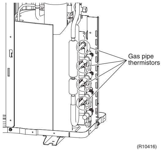 | ||
| 1 | Pull out the gas pipe thermistors. | ||
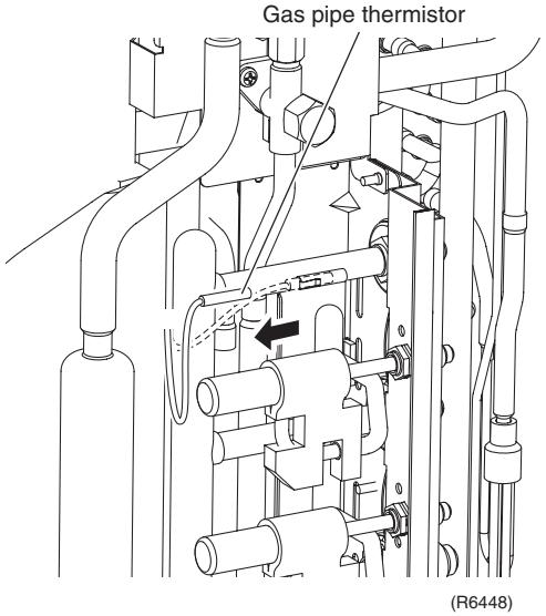 | |||
| 2 | Peel off the putty and pull out the liquid pipe thermistors. | 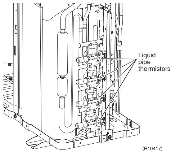 | |
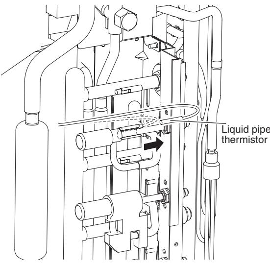 | |||
| 3 | Pull out the outdoor heat exchanger thermistor. | (R6450) | |
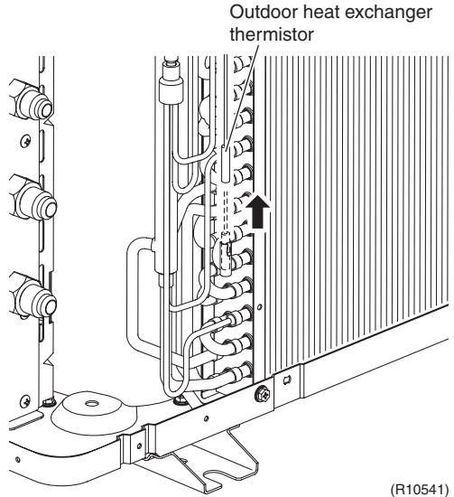 | |||
| 4 | Remove the clip from the outdoor heat exchanger thermistor. | 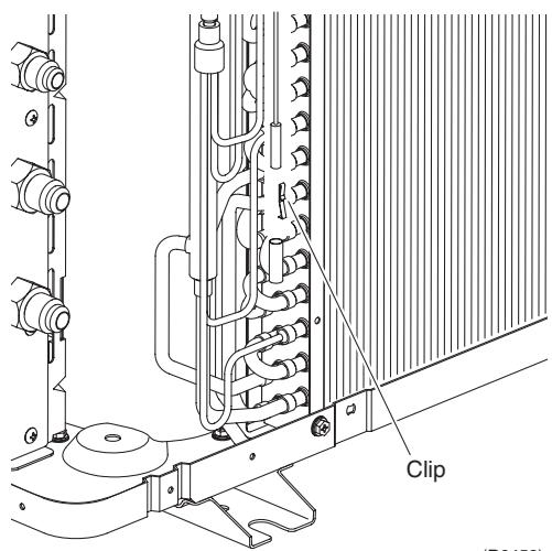 (H6452) (H6452) | ■ Be careful not to lose the clip. |
| 5 | Slightly open the sound blanket (outer). | 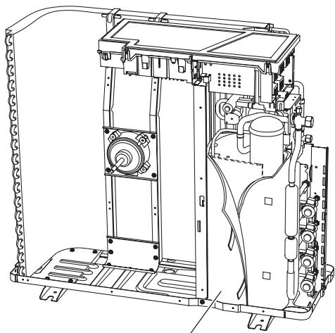 Sound blanket (outer) (R10418) Sound blanket (outer) (R10418) | |
| 6 | Remove the sound blanket (top upper). | 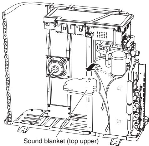 (R10419) (R10419) | |
| 7 | Remove the discharge pipe thermistor. |  | |
| 8 | Remove the fixture. | 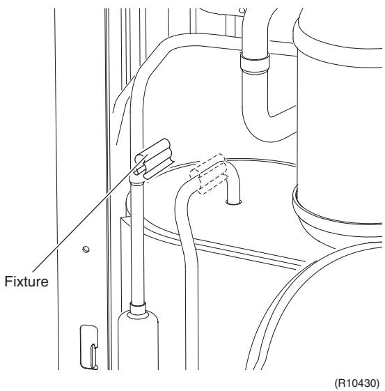 | |
| 3. Remove the four way valve coil. | 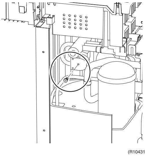 | ||
| 1 | Remove the screw. | ||
| 2 | Remove the four way valve coil. | 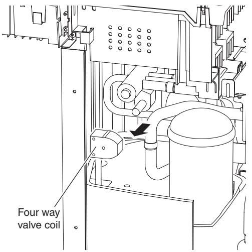 (R10432) (R10432) | |
2.6 Removal of Sound Blankets
Procedure

Warning
Be sure to wait for 10 minutes or more after turning off all power supplies before disassembling work.
| Step | Procedure | Points | |
| 1 | Open the sound blanket (outer). | 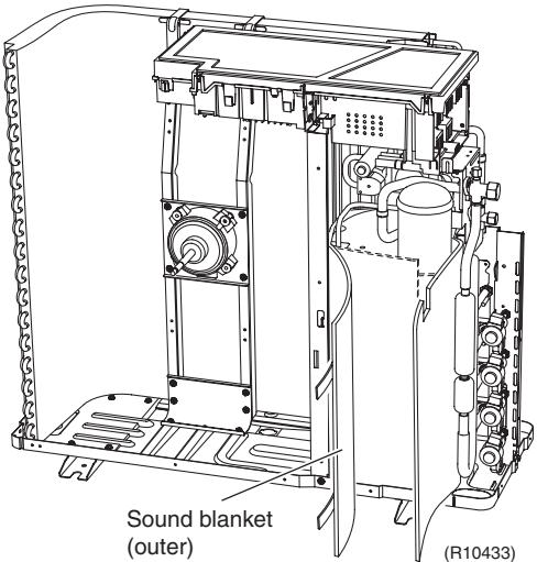 | ■ The sound blanket is fragile. Carefully pass the blanket through the discharge pipe. |
| 2 | Remove the sound blanket (top upper). | 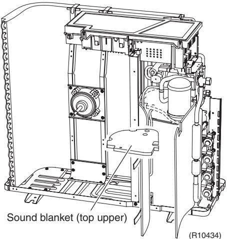 | |
| 3 | Remove the screw from the partition plate and push the plate to the left slightly for easy work. | 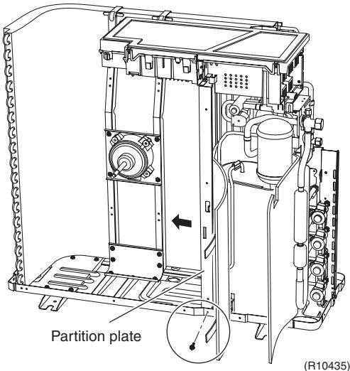 | |
| 4 | Remove the sound blanket (outer). | 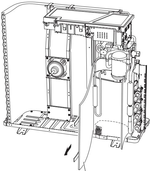 Sound blanket (outer) (R10436) Sound blanket (outer) (R10436) | ■ The sound blanket is fragile. |
| 5 | Remove the sound blanket (top inner). | ■ The sound blanket is fragile. Carefully pass the blanket through the discharge pipe. | |
| 6 | Open the sound blanket (inner) and pass it through the part of the mufflers. | 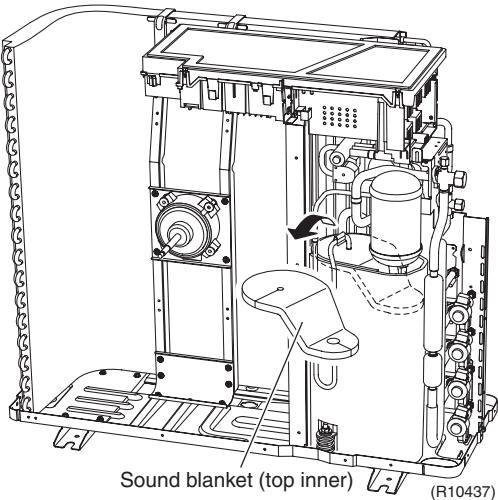 | |
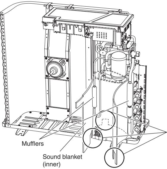 (R10438) (R10438) | ■ The sound blanket is fragile. Be careful of the notches of the compressor mount (3 locations). | ||
| 7 | Remove the sound blanket (inner). | 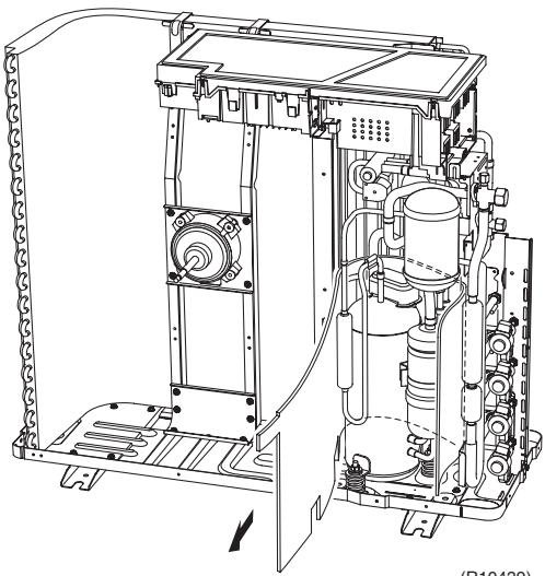 (H10432) (H10432) | |
2.7 Removal of Compressor
Procedure

Warning
Be sure to wait for 10 minutes or more after turning off all power supplies before disassembling work.
| Step | Procedure | Points | |
| 1 | Remove the terminal cover. | 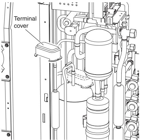 | |
| 2 | Disconnect the compressor lead wires. | (R6466) | ■ U : red, V : yellow, W : blue |
| 3 | Remove the overload protector. | 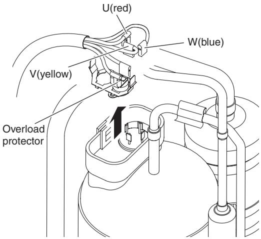 | |
| 4 | Remove the 3 nuts. | (R9471) | ■ Disconnect the pipings, referring to page 366. |
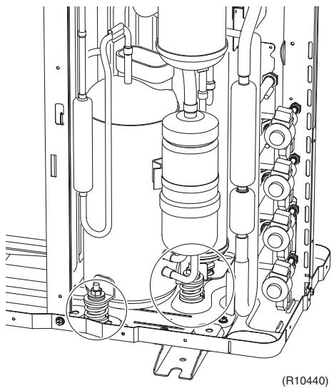 | |||
Part 8
Trial Operation and Field Settings
- Pump Down Operation....404
- Forced Operation 405
- Wiring Error Check Function 406
- Trial Operation .... 408
4.1 RA Indoor Unit - FTXG, FTXS, CTXS, FVXG, FVXS, FLXS, FDXS Series....408
4.2 SA Indoor Unit - FCQG, FFQ, FHQ, FDBQ, FBQ Series 410
- Field Settings ....412
5.1 Outdoor Unit 412
5.2 RA Indoor Unit - FTXG, FTXS, CTXS, FVXG, FVXS, FLXS, FDXS Series....415
5.3 SA Indoor Unit - FCQG, FFQ, FHQ, FDBQ, FBQ Series 419
- Application of Silicon Grease to a Power Transistor and a Diode Bridge 423
1. Pump Down Operation
Outline
In order to protect the environment, be sure to conduct pump down operation when relocating or disposing the unit.
Detail
1) Remove the valve caps from the liquid stop valve and the gas stop valve.
2) Carry out forced cooling operation.
3) After 5 to 10 minutes, close the liquid stop valve with a hexagonal wrench.
4) After 2 to 3 minutes, close the gas stop valve and stop the forced cooling operation.
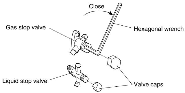
text_image
Gas stop valve Hexagonal wrench Close Liquid stop valve Valve caps(R14566)

Refer to page 405 for forced operation.
2. Forced Operation
Outline
Forced operation mode includes forced cooling and forced heating. Operation mode can be selected by the operation mode switch (SW2) on the outdoor unit. Press the forced operation [ON/OFF] switch (SW1) on the outdoor unit to start the operation.
Detail
| Item | Forced Cooling | Forced Heating |
| Conditions | 1) The indoor unit is not abnormal, but the indoor unit which is not in the freezing prohibiting zone is present in more than 1 room. | 1) The indoor unit is not abnormal. The indoor unit which is not in the peak-cut prohibited zone is present in more than 1 room. |
| 2) The outdoor unit is not abnormal and not in the 3-minute standby mode. | ← | |
| 3) The operating mode of the outdoor unit is the stop mode. | ← | |
| 4) The operation mode switch (SW2) on the outdoor unit is set to the cooling mode. | 4) The operation mode switch (SW2) on the outdoor unit is set to the heating mode. | |
| Start | Press the forced operation [ON/OFF] switch (SW1) on the outdoor unit. | ← |
| Operating room | All rooms:The command is sent to all the rooms where the transmission is normal. | ■ Only 1 room:The command is sent to one of the rooms which can be operate and the order of priority is A > B > C > D > E. Other rooms operation must be stopped. |
| Command frequency | • 40/50/52/58 class : 52 Hz• 68/75 class : 42 Hz• 80/90 class : 31 Hz | (Outdoor temperature : 2°C)• 40/50/52/58 class : 42 Hz• 68/75 class : 35 Hz• 80/90 class : 26 Hz |
| End | 1) Press the forced operation [ON/OFF] switch (SW1) on the outdoor unit again. | ← |
| 2) The operation ends automatically after 15 minutes. | 2) The operation ends automatically after 60 minutes. | |
| Others | The protection functions are prior to all others in the forced operation. | ← |
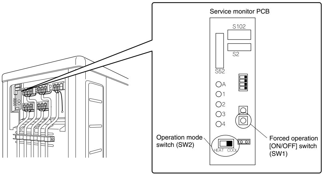
text_image
Service monitor PCB S102 S2 S52 ○A ○1 ○2 ○3 ○4 Operation mode switch (SW2) HEAT COOL Forced operation [ON/OFF] switch (SW1)(R12870)
3. Wiring Error Check Function
Outline
The convenient wiring error check function is designed for the microcomputer to correct wiring errors itself.
If local wiring is unclear in the case of buried piping, for example, just press the wiring error check switch that is behind the stop valve cover of the outdoor unit. Even if the connections for Room A and Room B are confused, the system may run without a hassle. Note that this check function does not work in the following cases.
■ For about 1 minute after the power is turned on (during initial setup).
■ For 3-minute standby period after the compressor has stopped.
■ When the outdoor temperature is below 5^ C.
■ If the indoor unit is in trouble (also in case of all-room transmission failure).
When the piping and wiring are perfect, there is no need to use this function.
Operation
- Remove the stop valve cover.
- Press the wiring error check switch (SW3) on the service monitor PCB of the outdoor unit, and the wiring error check function is activated.
- In about 10 \~ 20 minutes, the check finishes automatically.
- When the check is over, the service monitor LED indicators start blinking.
| LED | 1 | 2 | 3 | 4 | 5 | Judgment |
| Status | All blinking at once | Self-correction impossible | ||||
| Blinking one after another | Self-correction complete | |||||
■ Self-correction complete...The LED indicators 1 \~ 3 (3-room model), 1 \~ 4 (4-room model), or 1\~5 (5-room model) blink one after another.
■ Self-correction impossible...The LED indicators blink all at the same time.
* Transmission failure occurs at any of the indoor units.
* The indoor unit heat exchanger thermistor is disconnected.
* An indoor unit is in trouble (if a trouble occurs during the wiring error checking).
Emergency stop...Any of the LED indicators stays on.
Note:
- It takes about 10 \~ 20 minutes (after pressing the wiring error check switch) to complete the checking.
- Wrongly connected liquid and gas pipes cannot be self-corrected. Be sure to make the liquid pipe and the gas pipe in pairs.
- To cancel the wiring error check procedure halfway, press the wiring error check switch again. In this case, the memory of the microcomputer returns to its initial status (Room A wiring → Port A piping, Room B wiring → Port B piping).
- When replacing the outdoor unit PCB, be sure to use this function.
- Make the power side setting after doing the wiring error check. (Otherwise, if the wiring is reversed, the air-conditioners being connected are set up in the reverse way.)
Service monitor PCB
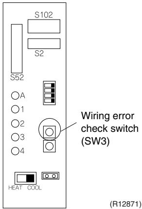
text_image
S102 S2 S52 ○A ○1 ○2 ○3 ○4 HEAT COOL Wiring error check switch (SW3) (R12871)Basic Knowledge
■ Refrigerant flows from Port A and on. The temperatures of the indoor heat exchanger thermistors are detected one by one to check up the matching between the piping and wiring.
■ With this function on, freezing (crackling) noise may be heard from the indoor unit. This is not a problem. (This is because the heat exchanger temperature is made to drop below 0^ C in order to increase the detection accuracy.)
■ The indoor fan is made to turn on or off at the same time.
Checking the current setting data on the microcomputer memory
Those data can be checked by looking at the service monitor LED indicators, when the wiring error checking is over, during forced operation, at the stop of the system.
The LED indicators stop blinking when the forced operation is over.
LED1...Room A wiring, LED2...Room B wiring
1st blinking LED...Port A piping, 2nd blinking LED...Port B piping
The 1st blinking LED means the room that is connected with Port A. The 2nd blinking LED means the one connected with Port B.
Example
Ex: Suppose the LED indicators are blinking as follows.
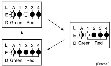
flowchart
graph TD
    A["Configuration 1"] --> B["Configuration 2"]
    B --> C["Configuration 3"]
    C --> D["Configuration 4"]
    A --> E["Output"]
    B --> F["Output"]
    C --> G["Output"]
    D --> H["Output"]
    style A fill:#f9f,stroke:#333
    style B fill:#ccf,stroke:#333
    style C fill:#cfc,stroke:#333
    style D fill:#fcc,stroke:#333
    style E fill:#ffc,stroke:#333
    style F fill:#cfc,stroke:#333
    style G fill:#fcc,stroke:#333
    style H fill:#ffc,stroke:#333
The above means that Port A is connected with Port B, and Port B with Room A (or self-corrected this way.)
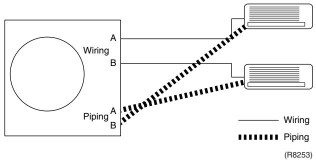
flowchart
graph TD
    A["Power Source"] -->|Wiring| B1["A"]
    A -->|Piping| B2["B"]
    B1 --> C1["Terminal 1"]
    B2 --> C2["Terminal 2"]
    C1 --> D1["Terminal 3"]
    C2 --> D2["Terminal 4"]
    style A fill:#fff,stroke:#000
    style B fill:#fff,stroke:#000
    style C1 fill:#fff,stroke:#000
    style C2 fill:#fff,stroke:#000
    style D1 fill:#fff,stroke:#000
    style D2 fill:#fff,stroke:#000
4. Trial Operation
4.1 RA Indoor Unit - FTXG, FTXS, CTXS, FVXG, FVXS, FLXS, FDXS Series
Outline
- Measure the power supply voltage and make sure that it falls in the specified range.
- Trial operation should be carried out in either cooling or heating operation.
- Carry out the trial operation in accordance with the operation manual to ensure that all functions and parts, such as flap movement, are working properly.
■ The air conditioner requires a small amount of power in its standby mode. If the system is not to be used for some time after installation, shut off the circuit breaker to eliminate unnecessary power consumption.
If the circuit breaker trips to shut off the power to the air conditioner, the system backs up the operation mode. The system then restarts operation with the previous operation mode when the circuit breaker is restored.
In cooling operation, select the lowest programmable temperature; in heating operation, select the highest programmable temperature.
■ Trial operation may be disabled in either operation mode depending on the room temperature.
■ After trial operation is complete, set the temperature to a normal level. (26°C \~ 28°C in cooling, 20°C \~ 24°C in heating)
■ For protection, the system does not start for 3 minutes after it is turned off.
Detail
ARC466 Series
(1) Press the [On/Off] button to turn on the system.
(2) Press the center of the [Temp] button and the [Mode] button at the same time.
(3) Select 7 ^- (trial operation) with the [Temp] ▲ or ▼ button.
(4) Press the [Mode] button to start the trial operation.
(5) Press the [Mode] button and select operation mode.
(6) Trial operation terminates in approx. 30 minutes and switches into normal mode. To quit a trial operation, press the [On/Off] button.

text_image
(3) ON 7 A On/Off Temp (2) (3) (2) (4) (5) Mode (1) (6) (R11676)ARC452 Series
(1) Press the [ON/OFF] button to turn on the system.
(2) Press the both of [TEMP] buttons and the [MODE] button at the same time.
(3) Press the [MODE] button twice.
(7) appears on the display to indicate that trial operation is selected.)
(4) Press the [MODE] button and select the operation mode.
(5) Trial operation terminates in approx. 30 minutes and switches into normal mode. To quit a trial operation, press the [ON/OFF] button.
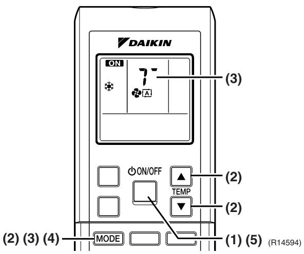
text_image
DAIKIN ON 7- A (3) ON/OFF ▲ TEMP (2) (2) MODE (1) (5) (R14594)ARC433 Series
(1) Press the [ON/OFF] button to turn on the system.
(2) Press the center of the [TEMP] button and the [MODE] button at the same time.
(3) Press the [MODE] button twice.
(7) appears on the display to indicate that trial operation is selected.)
(4) Press the [MODE] button and select the operation mode.
(5) Trial operation terminates in approx. 30 minutes and switches into normal mode. To quit a trial operation, press the [ON/OFF] button.
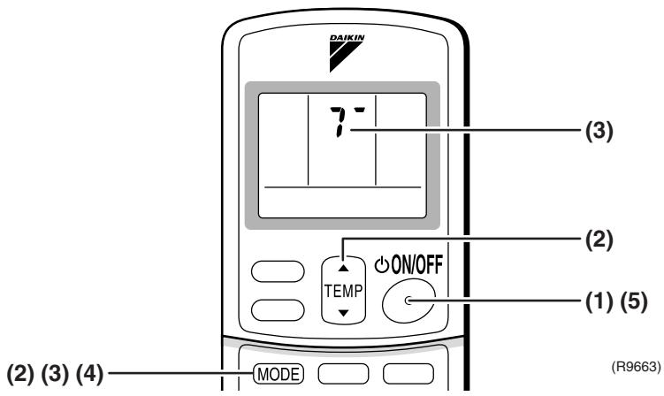
text_image
DAIKIN (3) (2) (1) (5) ON/OFF TEMP (2) (3) (4) MODE (R9663)4.2 SA Indoor Unit - FCQG, FFQ, FHQ, FDBQ, FBQ Series
4.2.1 Check points
To carry out test operation, check the followings:
- Check that the temperature setting of the remote controller is at the lowest level in cooling mode.
■ Go through the following checklist:
| Checkpoints | Cautions or warnings |
| Are all units securely installed? | ● Dangerous for turning over during storm● Possible damage to pipe connections |
| Is the earth wire installed according to the applicable local standard? | Dangerous if electric leakage occurs. |
| Are all air inlets and outlets of the indoor and outdoor units unobstructed? | ● Poor cooling● Poor heating |
| Does the drain flow out smoothly? | Water leakage |
| Is piping adequately heat-insulated? | Water leakage |
| Have the connections been checked for refrigerant leakage? | ● Poor cooling● Poor heating● Stop |
| Is the supply voltage conform to the specifications on the name plate? | Incorrect operation |
| Are the cable sizes as specified and according to local regulations? | Damage of cables |
| Are the remote controller signals received by the unit? | No operation |
4.2.2 Test operation
BRC1D528
| Step | Action |
| 1 | Turn on the power supply more than 6 hours before test operation. |
| 2 | Open the gas stop valve. |
| 3 | Open the liquid stop valve. |
| 4 | Set to cooling operation with the remote controller and start operation by pressing [ON/OFF] button ( ⏻ ). |
| 5 | Press the [INSPECTION/TEST OPERATION] button ( ⏱ ) 4 times (2 times for wireless remote controller) and operate at test operation mode for 3 minutes. |
| 6 | Press the [AIRFLOW DIRECTION ADJUST] button ( ⏻ ) to make sure the unit is in operation. |
| 7 | Press the [INSPECTION/TEST OPERATION] button ( ⏱ ) and operate normally. |
| 8 | Confirm all the function of unit according to the operation manual. |
| 9 | If the decoration panel has not been installed, turn off the power after the test operation. |
BRC1E51A7
| Step | Action | Remote controller |
| Before test operation | ||
| 1 | Turn on the power supply more than 6 hours before test operation. | |
| 2 | Open the gas stop valve. | |
| 3 | Open the liquid stop valve. | |
| How to activate test operation | ||
| 4 | Press and hold the [Cancel] button ( ↺ ) for 4 seconds to enter the Field setting menu. | |
| 5 | Use the ▼▲ buttons to select Test operation ON/OFF and push the [Menu/Enter] button ( ↺ ). | 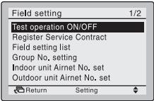 (R12872) (R12872) |
| 6 | Test operation is displayed on the bottom of the basic screen. | 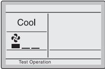 (R12873) (R12873) |
| 7 | Push the [ON/OFF] button ( ↺ ) within 10 seconds to start the test operation. | |
| How to check airflow direction | ||
| 8 | Push the [Menu/Enter] button ( ↺ ) to enter the Main Menu. | |
| 9 | Use the ▼▲ buttons to select Airflow direction and push the [Menu/Enter] button ( ↺ ). | 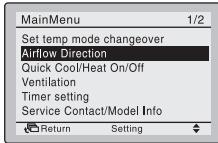 (R12874) (R12874) |
| 10 | Check that the airflow direction is actuated according to the setting and push the [Menu/Enter] button ( ↺ ). | 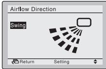 (R12875) (R12875) |
| How to deactivate test operation | ||
| 11 | Press and hold the [Cancel] button ( ↺ ) for 4 seconds to enter the Field setting menu. | |
| 12 | Use the ▼▲ buttons to select Test operation ON/OFF in the menu and push the [Menu/Enter] button ( ↺ ). | 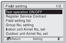 (R12876) (R12876) |
5. Field Settings
5.1 Outdoor Unit
5.1.1 Priority Room Setting
Outdoor electronic expansion valves are controlled to provide more capacity to the prioritized room.
■ Setting method
Turn off the circuit breaker before changing the setting.
Only one room can be set as the priority room (By turning on one of the SW4 on the service monitor PCB of the outdoor unit).
■ The control starts when all the following conditions are met.
* Priority room setting is made.
* "POWERFUL" signal from the priority room unit is received.

Note: The operation mode of the priority room unit has precedence.
■ Cancellation of control
The control function is canceled when the “POWERFUL” operation mode is switched off or 20 minutes elapse after “POWERFUL Operation” started.
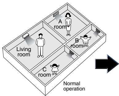
flowchart
graph TD
    A["Living room"] --> B["A room"]
    B --> C["B room"]
    C --> D["C room"]
    style A fill:#f9f,stroke:#333
    style B fill:#ccf,stroke:#333
    style C fill:#cfc,stroke:#333
    style D fill:#fcc,stroke:#333
    note right of D Normal operation
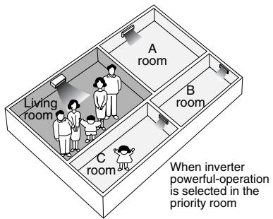
text_image
Living room A room B room C room When inverter power-operation is selected in the priority roomThe prioritized room will be heated/cooled much more quickly
(R1396)
Service monitor PCB
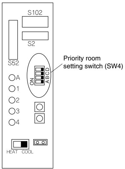
text_image
S102 S2 S52 ON ABCD Priority room setting switch (SW4) A 1 2 3 4 HEAT COOL3 or 4-room model
(R17271)
Service monitor PCB
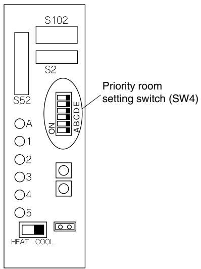
text_image
S102 S2 S52 ON ABCDE Priority room setting switch (SW4) A 1 2 3 4 5 HEAT COOL5-room model
(R17272)
5.1.2 COOL / HEAT Mode Lock
Use the [S15] connector to set the unit to cooling only or heating only.
Setting to heating only (H): Short-circuit pins 1 and 3 of the connector [S15].
Setting to cooling only (C): Short-circuit pins 3 and 5 of the connector [S15].
The following specifications apply to the connector housing and pins.
JST products Housing: VHR-5N
Pin: SVH-21T-1, 1
Note that forced operation is also possible in cooling / heating mode.
* The illustration is for 68/75/80/90 models as representative. On 40/50/52/58 models, the location of the [S15] connector is slightly different.
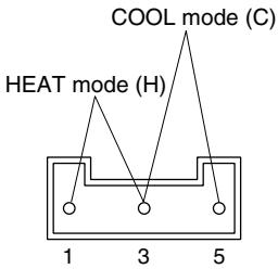
text_image
COOL mode (C) HEAT mode (H) 1 3 5Arrow view A
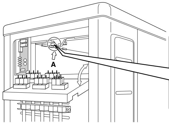
text_image
A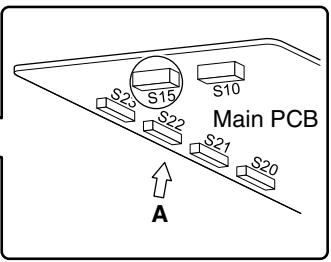
text_image
S2 S15 S10 Main PCB S22 S21 S20 A(R14567)
5.1.3 NIGHT QUIET Mode
If NIGHT QUIET mode is to be used, initial settings must be made when the unit is installed. Explain the function of NIGHT QUIET mode, as described below, to the customer, and confirm whether or not the customer wants to use NIGHT QUIET mode.
NIGHT QUIET mode function reduces operating noise of the outdoor unit at nighttime. This function is useful if the customer is worried about the effects of the operating noise on the neighbors. However, if NIGHT QUIET mode is running, cooling capacity is reduced.
■ Procedure
- Remove the SW5 jumper switch on the service monitor PCB of the outdoor unit. Once the settings are complete, reset the power.
Service monitor PCB
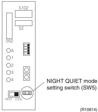
text_image
S102 S2 S52 A 1 2 3 4 HEAT COOL NIGHT QUIET mode setting switch (SW5) (R10814)- Install the removed jumper switch as described below. This jumper switch is needed later to disable this setting.
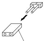
Jumper switch

After removing
(R10813)
5.1.4 ECONO-mode-proof Setting
Outline
When installing in hotels, you can make ECONO mode ineffective on the outdoor unit.
Operation
The ECONO mode can be switched over between "effective" and "ineffective" by pressing the forced operation [ON/OFF] switch (SW1) on the outdoor unit and wiring error check switch (SW3) on the outdoor unit at the same time and holding them for 5 seconds while the compressor is stopped. The LEDs are lit in turn for 15 seconds to show the ECONO mode status.
The factory setting is "effective".
| LED flashing order | effective → ineffective | ineffective → effective |
| 3 or 4-room model | 4 → 3 → 2 → 1 | 1 → 2 → 3 → 4 |
| 5-room model | 5 → 4 → 3 → 2 → 1 | 1 → 2 → 3 → 4 → 5 |
5.2 RA Indoor Unit - FTXG, FTXS, CTXS, FVXG, FVXS, FLXS, FDXS Series
5.2.1 Model Type Setting
ARC452A1, ARC452A3, ARC466A6
■ The remote controller is common to the heat pump model and cooling only model. Use the DIP switch on the remote controller to set the model type.
■ Set the DIP switch as shown in the illustration. (The factory set is the heat pump side.)
- Heat pump model: Set the DIP switch to H/P.
- Cooling only model: Set the DIP switch to C/O.
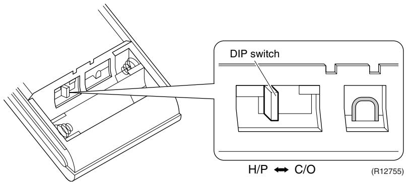
text_image
DIP switch H/P ↔ C/O (R12755)5.2.2 When 2 Units are Installed in 1 Room
Outline
When 2 indoor units are installed in 1 room, 1 of the 2 indoor units and the corresponding wireless remote controller can be set for different address.
Both the indoor unit PCB and the wireless remote controller need alteration.
The method of address setting varies depending on the type of indoor unit and the series of wired remote controller. Refer to the following pages for the appropriate indoor unit and wireless remote controller.
Wall Mounted Type
(1) Remove the front grille.
(2) Remove the electrical box.
(3) Remove the shield plate of the electrical box.
(4) Cut the address setting jumper JA on the PCB.
FTXG Series
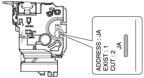
text_image
ADDRESS: JA EXIST: 1 CUT: 2 JA(Bottom of electrical box)
FTXS-K, CTXS-K Series
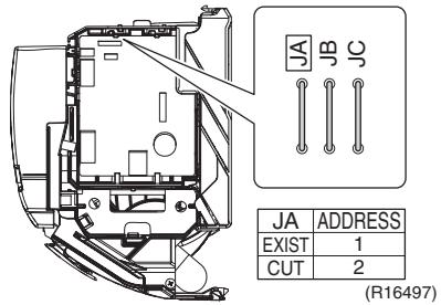
text_image
JA JB JC JA ADDRESS EXIST 1 CUT 2 (R16497)(R12036)
FTXS-J Series
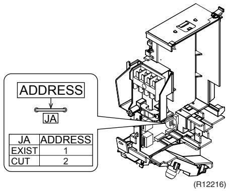
text_image
ADDRESS JA JA ADDRESS EXIST 1 CUT 2 (R12216)FTXS-G Series
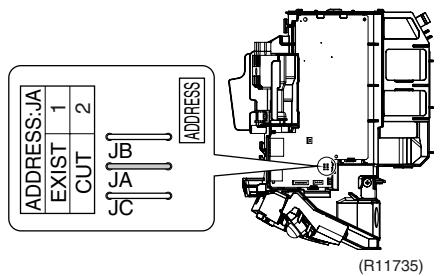
text_image
ADDRESS:JA EXIST 1 2 CUT JB JA JC ADDRESS (R11735)Floor Standing Type
FVXG Series
(1) Remove the front panel, air filters and front grille.
(2) Remove the screw, and remove the service cover.
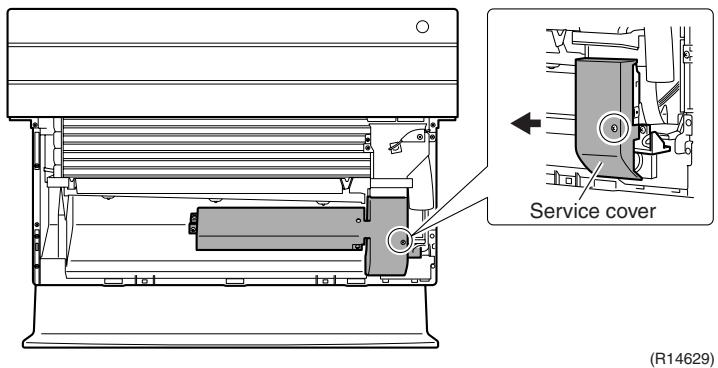
text_image
Service cover (R14629)(3)Turn on the DIP switch [S2W-1] on the service PCB.
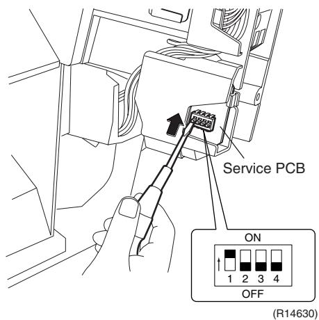
text_image
Service PCB ON 1 2 3 4 OFF (R14630)* Keep the other switches as factory setting (OFF).
FVXS Series
1) Remove the front grille.
2) Lift the sensor PCB fixing plate and remove the front shield plate.
3) Disconnect the connectors [S1] [S41] [S42].
4) Remove the electric box (1 screw).
5) Pull out the indoor heat exchanger thermistor.
6) Remove the shield plate (8 tabs).
7) Cut the address setting jumper JA on the indoor unit PCB.
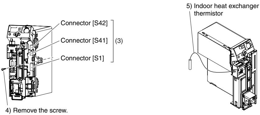
text_image
Connector [S42] Connector [S41] (3) Connector [S1] 4) Remove the screw. 5) Indoor heat exchanger thermistor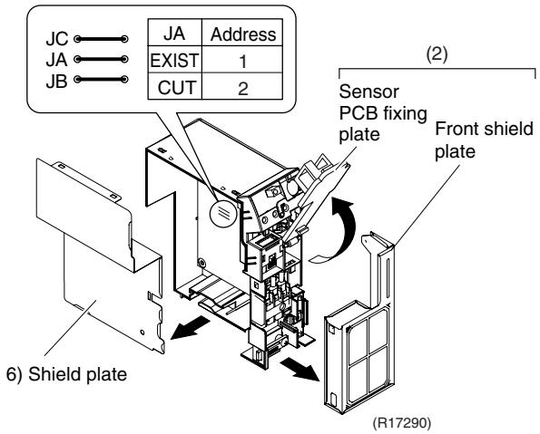
text_image
JC JA JB JA Address EXIST 1 CUT 2 (2) Sensor PCB fixing plate Front shield plate 6) Shield plate (R17290)Floor / Ceiling
Suspended Dual
Type
■ Cut the jumper JA on PCB.
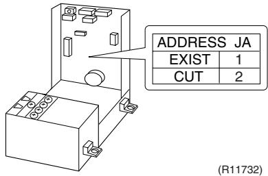
text_image
ADDRESS JA EXIST 1 CUT 2 (R11732)Duct Connected Type
■ Cut the jumper JA on PCB.
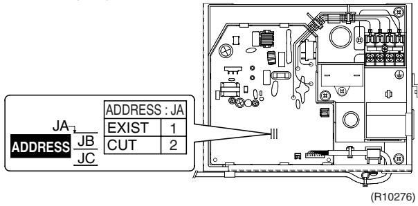
text_image
JA ADDRESS JB JC ADDRESS : JA EXIST 1 CUT 2 (R10276)Wireless Remote Controller
(1) Remove the cover and take it off.
(2) Cut the address setting jumper.
ARC466 series
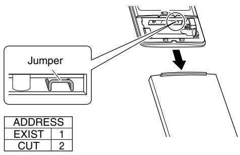
text_image
Jumper ADDRESS EXIST 1 CUT 2(R12037)
ARC452 series

text_image
Jumper ADDRESS EXIST 1 CUT 2 (R12065)ARC433 series
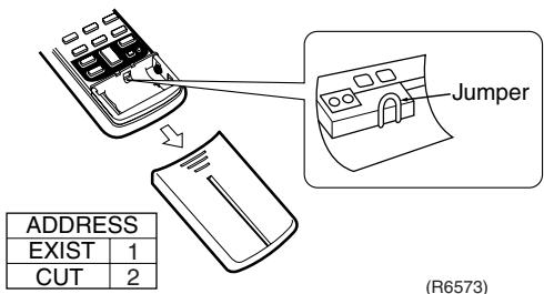
text_image
ADDRESS EXIST 1 CUT 2 Jumper (R6573)(R6573)
5.2.3 Jumper and Switch Settings
| Jumper (on indoor unit PCB) | Function | When connected (factory set) | When cut |
| JB | Fan speed setting when compressor stops for thermostat OFF. (effective only at cooling operation) | Fan speed setting ; Remote controller setting | Fan speed setting; “0” (The fan stops.) |
| JC | Power failure recovery function | Auto-restart | The unit does not resume operation after recovering from a power failure. Timer settings are cleared. |
| Switch (on indoor unit PCB) | Function | OFF (factory set) | ON |
| SW2-4 | Upward airflow limit setting | Exposed or half embedded installation | Set the switch to ON position when you install the indoor unit embedded in the wall to avoid condensation. |
| Switch (on indoor unit PCB) | Function | FLOOR (factory set) | CEILING |
| SW2 | Installation style changeover | When installed as the floor mounted type | When installed as the ceiling suspended type |

For the location of the jumper and the switch, refer to the following pages.
Wall Mounted Type: page 42, 45, 47, 50
Floor Standing Type: page 53, 56
Floor / Ceiling Suspended Dual Type: page 58
Duct Connected Type: page 60
5.3 SA Indoor Unit - FCQG, FFQ, FHQ, FDBQ, FBQ Series
5.3.1 How to Change the Field Settings
Outline
If optional accessories are mounted on the indoor unit, the indoor unit setting may have to be changed. Refer to the instruction manual for each optional accessory.
Wired remote controller
BRC1D528
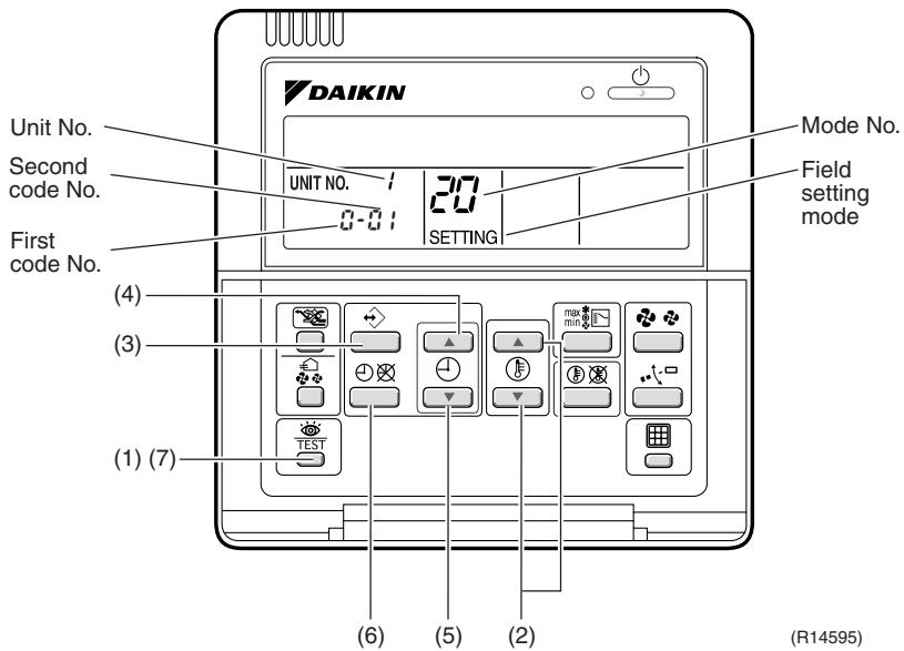
text_image
DAIKIN Unit No. Second code No. First code No. (4) (3) (1) (7) UNIT NO. 20 20 SETTING Mode No. Field setting mode TEST (6) (5) (2) (R14595)To set the field settings, you have to change:
■ Mode No.
■ First code No.
■ Second code No.
| Step | Action |
| 1 | Press the [INSPECTION/TEST OPERATION] button for 4 seconds during normal mode to enter the field setting mode. |
| 2 | Press the [TEMPERATURE ADJUST] button to select the desired mode No. |
| 3 | ■ If the indoor unit is under group control, all settings for all the indoor units are set at the same time. Use the codes 10 to 15 to apply this group control and proceed to the next step. ■ If you want to set the indoor units of one group individually or if you want to read out the last settings, use the codes 20 to 25 which are displayed in brackets. Press the [PROGRAMMING] button to select the indoor unit No. for which you want to adjust the field settings. |
| 4 | Press the upper part of the [TIME ADJUST] button to select the first code No. |
| 5 | Press the lower part of the [TIME ADJUST] button to select the second code No. |
| 6 | Press the [SCHEDULE TIMER] button to confirm the setting. |
| 7 | Press the [INSPECTION/TEST OPERATION] button to return to normal mode. |
BRC1E52A7, BRC1E52B7
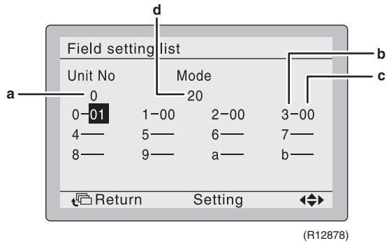
text_image
Field setting list Unit No Mode 20 3-00 a 0 1-00 2-00 7- 4 5 6 7- 8 9 a b Return Setting (R12878)a Unit No.
b First code No.
c Second code No.
d Mode
| Step | Action | Remote controller |
| 1 | Press and hold the [Cancel] button ( [IMAGE] ) for 4 seconds to enter the Field setting menu. | |
| 2 | Use the ▼▲ buttons to select Field setting list and push the [Menu/Enter] button ( [IMAGE]). | 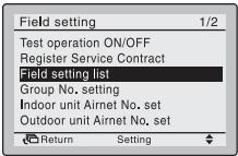 (R12879) (R12879) |
| 3 | Use the ▼▲ buttons to select the desired Mode. | |
| 4 | During group control, when setting by each indoor unit (Mode 20, 21, 22 and 23 have been selected), push the ◀ button to highlight and ▼▲ buttons to select the INDOOR UNIT NO. to be set. This operation is unnecessary when setting by group. | |
| 5 | Highlight the second code No. to be changed using the ◀▶ buttons, and use the ▼▲ buttons to select the desired second code No. | When setting by group, all of the second code No. that may be set are displayed as “*”. |
| 6 | Push the [Menu/Enter] button ( [IMAGE] ) to display the confirmation screen. | |
| 7 | Use the ◀▶ buttons to select Yes and push the [Menu/Enter] button ( [IMAGE]). | When multiple setting changes are needed, repeat steps 3 to 7. |
| 8 | Push the [Cancel] button ( [IMAGE] ) 2 times to return to basic screen. |
5.3.2 Overview of the Field Settings
| Mode No. | First Code No. | Description of setting | Second Code No. | ||||||
| 01 | 02 | 03 | 04 | ||||||
| 10 (20) | 0 | Filter cleaning sign interval | Ultra longlife filter | Light | Approx. 10,000 hrs. | Heavy | Approx. 5,000 hrs. | — | — |
| Longlife filter | Approx. 2,500 hrs. | Approx. 1,250 hrs. | |||||||
| 1 | Longlife filter type | Longlife filter | Ultra longlife filter | — | — | ||||
| 2 | Remote controller thermistor | Enabled | Disabled | — | — | ||||
| 3 | Filter cleaning sign | Display | No display | — | — | ||||
| 11 (21) | 0 | Indoor unit number of simultaneous operation system | Pair | Twin | Triple | Double twin | |||
| 1 | Simultaneous operation system individual setting | Unified setting | Individual setting | — | — | ||||
| 7 | External static pressure setting | Airflow adjustment is OFF | Completion of airflow adjustment | Start of airflow adjustment | — | ||||
| 12 (22) | 1 | Forced ON/OFF function | Forced OFF | ON/OFF operation | — | — | |||
| 2 | Thermostat differential changeover (setting for when using remote sensor) | 1°C | 0.5°C | — | — | ||||
| 13 (23) | 0 | High air outlet velocity (for high ceiling applications) | ≤2.7 m | 2.7 ~ 3.0 m | 3.0 ~ 3.5 m | — | |||
| 1 | Selection of airflow direction (setting for when a blocking pad kit has been installed) | 4-way flow | 3-way flow | 2-way flow | — | ||||
| 3 | Selection of airflow function (setting for when using a decoration panel for outlet) | Equipped | Not equipped | — | — | ||||
| 4 | Airflow direction range setting | Upper | Normal | Lower | — | ||||
| 6 | External static pressure | Refer to Note 2. | |||||||
| 14 (24) | 2 | Dust collection sign interval | Approx. 1,250 hrs. | Approx. 2,500 hrs. | Approx. 5,000 hrs. | — | |||
| 3 | Filter replacement sign | No display | Approx. 32,000 hrs. | Approx. 48,000 hrs. | Approx. 72,000 hrs. | ||||
| 4 | Panel indicator (green) ON/OFF | The indicator lights up during both air conditioning operation and filter auto-cleaning. | The indicator can light up only during filter auto-cleaning. | The indicator does not light up during both air conditioning operation and filter auto-cleaning. | — | ||||
| 8 | Selection of the automatic control operation lock mode | ON | OFF | — | — | ||||
| 9 | Dust amount setting | Standard | Heavy | — | — | ||||
| 15 (25) | 3 | Drain pump operation with humidifying | Not equipped | Equipped | — | — | |||
: factory set

Note: 1. Any function that is not available on the indoor unit is not displayed.
2.
| External static pressure (Pa) | |||||
| Mode No. | First code No. | Second code No. | FBQ | ||
| 35 class | 50 class | 60 class | |||
| 13 (23) | 6 | 03 | 30 | 30 | 30 |
| 04 | 35 | 35 | 40 | ||
| 05 | 40 | 40 | 50 | ||
| 06 | 45 | 45 | 60 | ||
| 07 | 50 | 50 | 70 | ||
| 08 | 60 | 60 | 80 | ||
| 09 | 70 | 70 | 90 | ||
| 10 | 80 | 80 | 100 | ||
| 11 | 90 | 90 | — | ||
| 12 | 100 | 100 | — | ||
: factory set
5.3.3 MAIN / SUB Setting when Using 2 Wired Remote Controllers
Outline
The MAIN / SUB setting is necessary when 1 indoor unit is controlled by 2 remote controllers. When you use 2 remote controllers (control panel and separate remote controller), set one to MAIN and the other to SUB.
Detail
The remote controllers are factory set to MAIN, so you only have to change one remote controller from MAIN to SUB.
BRC1D528
| Step | Action |
| 1 | Insert a flat screwdriver into the groove between the upper and lower part of the remote controller, as shown in the illustration below. Gently pry off the upper part of the controller, working from the two possible positions.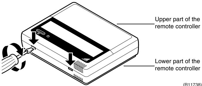 |
| 2 | Set the [MAIN / SUB changeover] switch on the PCB to “S”.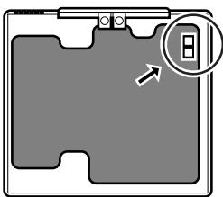 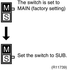 |
BRC1E52A7, BRC1E52B7
| Step | Action | Remote controller |
| 1 | Put on the power for both remote controllers. | |
| 2 | Determine which one is the sub/main remote controller. | |
| 3 | When Error code: U5 - Connection under check Please wait for a moment is displayed on both remote controllers, push and hold the [Operation mode selector] button (◆) of the sub remote controller for 4 seconds. | 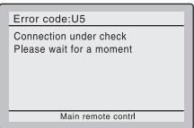 (R12880) (R12880) |
| 4 | The sub remote controller now displays Sub remote contrl.Note) The main remote controller still displays Main remote contrl. |  (R12881) (R12881) |
| 5 | After a few seconds, the basic screen is displayed. |
6. Application of Silicon Grease to a Power Transistor and a Diode Bridge
Applicable Models
All outdoor units using inverter type compressor for room air conditioner.
When the printed circuit board (PCB) of an outdoor unit is replaced, it is required that silicon grease (*1) is certainly applied to the heat radiation part (the contact point to the radiation fin) of the power transistor and diode bridge.
*1: Parts number of the silicon grease – 1172698 (Drawing number 3FB03758-1)
Details
The silicon grease is an essential article for encouraging the heat radiation of the power transistor and the diode bridge. Applying the paste should be implemented in accordance with the following instruction.
Note: There is the possibility of failure with smoke in case of bad heat radiation.
■ Wipe off the old silicon grease completely on a radiation fin.
■ Apply the silicon grease evenly to the whole.
■ Do not leave any foreign object such as solder or paper waste between the power transistor and the radiation fin, and also the diode bridge, and the radiation fin.
■ Tighten the screws of the power transistor and the diode bridge, and contact to the radiation fin without any gap.
The shape of electrical box and PCB vary depending on the model.
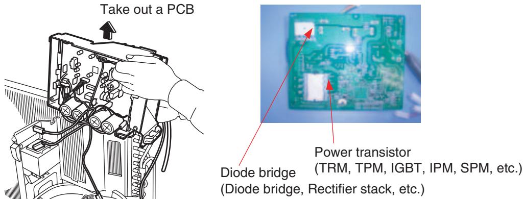
text_image
Take out a PCB Diode bridge (Diode bridge, Rectifier stack, etc.) Power transistor (TRM, TPM, IGBT, IPM, SPM, etc.)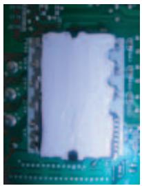
natural_image
Close-up of a green printed circuit board with a white plastic cover (no visible text or symbols)OK : Evenly applied silicon grease.
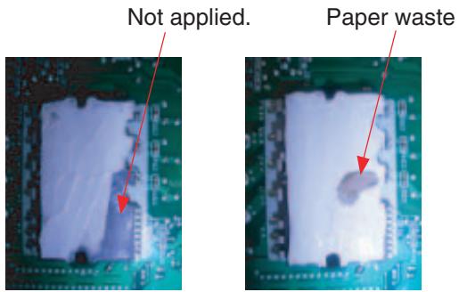
text_image
Not applied. Paper wasteNG : Not evenly applied
NG : Foreign object
(R9056)
Part 9
Appendix
- Piping Diagrams......425
1.1 Outdoor Unit 425
1.2 Indoor Unit 430
- Wiring Diagrams......437
2.1 Outdoor Unit 437
2.2 Indoor Unit 442
1. Piping Diagrams
1.1 Outdoor Unit
1.1.1 Cooling Only
3MKS50E3V1B
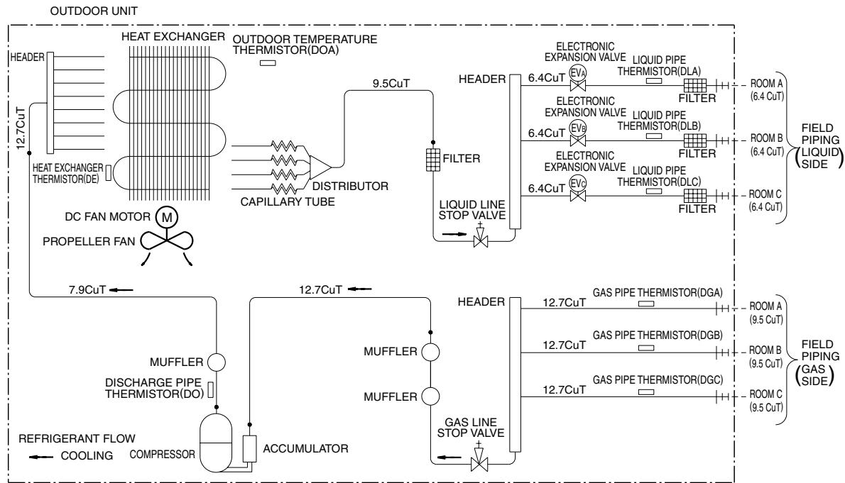
flowchart
graph TD
    A["OUTDOOR UNIT"] --> B["HEAT EXCHANGER"]
    B --> C["HEAT EXCHANGER THERMISTOR(DE)"]
    C --> D["Distributor"]
    D --> E["CAPILLARY TUBE"]
    E --> F["DISTRIBUTOR"]
    F --> G["9.5CuT"]
    G --> H["FILTER"]
    H --> I["LIQUID LINE STOP VALVE"]
    I --> J["ELECTRONIC EXPANSION VALVE"]
    J --> K["6.4CuT"]
    K --> L["FILTER"]
    L --> M["LIQUID PIPE THERMISTOR(DLA)"]
    M --> N["FILTER"]
    N --> O["ROOM A (6.4 CuT)"]
    N --> P["ROOM B (6.4 CuT)"]
    N --> Q["ROOM C (6.4 CuT)"]

    R["REFRIGERANT FLOW"] --> S["MUFFLER"]
    S --> T["DISCHARGE PIPE THERMISTOR(DO)"]
    T --> U["ACCUMULATOR"]
    U --> V["MUFFLER"]
    V --> W["GAS LINE STOP VALVE"]
    W --> X["ELECTRONIC EXPANSION VALVE"]
    X --> Y["6.4CuT"]
    Y --> Z["FILTER"]
    Z --> AA["LIQUID PIPE THERMISTOR(DLB)"]
    AA --> AB["FILTER"]
    AB --> AC["ROOM A (9.5 CuT)"]
    AB --> AD["ROOM B (9.5 CuT)"]
    AB --> AE["ROOM C (9.5 CuT)"]

    AF["PROPELLER FAN"] --> AG["M"]
    AG --> AH["DC FAN MOTOR"]
    AH --> AI["7.9CuT"]

    AJ["HEATER"] --> AK["12.7CuT"]

    AL["OUTDOOR TEMPERATURE THERMISTOR(DOA)"] --> AM["HEADER"]

    AN["HEAT EXCHANGER THERMISTOR(DOA)"] --> AO["9.5CuT"]

    AP["HEATER"] --> AQ["FILTER"]

    AR["HEATER"] --> AS["Liquid Line STOP VALVE"]

    AT["HEATER"] --> AU["ELECTRONIC EXPANSION VALVE"]
    AU --> AV["6.4CuT"]
    AV --> AW["FILTER"]
    AW --> AX["LIQUID PIPE THERMISTOR(DLC)"]
    AX --> AY["FILTER"]

    AZ["HEATER"] --> BA["ELECTRONIC EXPANSION VALVE"]
    BA --> BB["6.4CuT"]
    BB --> BC["FILTER"]
    BC --> BD["LIQUID PIPE THERMISTOR(DLB)"]
    BD --> BE["FILTER"]

    BF["FILTER"] --> BG["ELECTRONIC EXPANSION VALVE"]
    BG --> BH["6.4CuT"]
    BH --> BI["FILTER"]
    BI --> BJ["LIQUID PIPE THERMISTOR(DLC)"]
    BJ --> BK["FILTER"]

    BL["FILTER"] --> BM["ELECTRONIC EXPANSION VALVE"]
    BM --> BN["6.4CuT"]
    BN --> BO["FILTER"]

    BP["FILTER"] --> BP["ELECTRONIC EXPANSION VALVE"]
    BP --> BQ["FILTER"]

    BQ --> BR["ELECTRONIC EXPANSION VALVE"]
    BR --> BS["6.4CuT"]
    BS --> BT["FILTER"]

    BU["FILTER"] --> BV["ELECTRONIC EXPANSION VALVE"]
    BV --> BW["FILTER"]

    BX["FILTER"] --> BY["ELECTRONIC EXPANSION VALVE"]
    BY --> BZ["FILTER"]

    CA["FILTER"] --> CAE["ELECTRONIC EXPANSION VALVE"]
    CAE --> CB["FILTER"]

    CC["FILTER"] --> CC["ELECTRONIC EXPANSION VALVE"]
    CC --> DC["FILTER"]

    DD["FILTER"] --> DD["ELECTRONIC EXPANSION VALVE"]
    DD --> DE["FILTER"]

    EF["FILTER"] --> EF["ELECTRONIC EXPANSION VALVE"]
    EF --> BG["FILTER"]

    BHF["FILTER"] --> BHG["ELECTRONIC EXPANSION VALVE"]
    BHG --> BHJ["FILTER"]

    BIH["FILTER"] --> BIJ["ELECTRONIC EXPANSION VALVE"]
    BIJ --> BJ["FILTER"]

    BKH["FILTER"] --> BKJ["ELECTRONIC EXPANSION VALVE"]
    BKJ --> BL["FILTER"]

    BNJ["HAND"] --> BNK["ELECTRONIC EXPANSION VALVE"]
    BNK --> BLQ["FILTER"]

    BNL["HAND"] --> BNM["ELECTRONIC EXPANSION VALVE"]
    BNM --> BNQ["FILTER"]

    BNQ["HAND"] --> BNQLE["ELECTRONIC EXPANSION VALVE"]
    BNQLE --> BNQH["FILTER"]
3D052056C
4MKS58E3V1B
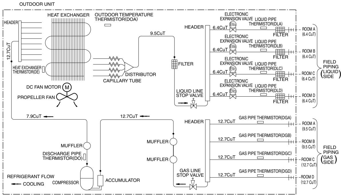
flowchart
graph TD
    A["OUTDOOR UNIT"] --> B["HEAT EXCHANGER"]
    B --> C["9.5CuT"]
    C --> D["DISTRIBUTOR CAPILLARY TUBE"]
    D --> E["FILTER"]
    E --> F["LIQUID LINE STOP VALVE"]
    F --> G["HEADER"]
    G --> H["ELECTRONIC EXPANSION VALVE LIQUID PIPE THERMISTOR(DLA)"]
    H --> I["FILTER"]
    I --> J["ROOM A (6.4 CuT)"]
    I --> K["ROOM B (6.4 CuT)"]
    I --> L["ROOM C (6.4 CuT)"]
    I --> M["ROOM D (6.4 CuT)"]
    N["PROPELLER FAN"] --> O["MUFFLER DISCHARGE PIPE THERMISTOR(DO)"]
    O --> P["12.7CuT"]
    P --> Q["ACCUMULATOR"]
    Q --> R["MUFFLER"]
    R --> S["HEADER"]
    S --> T["GAS PIPE THERMISTOR(DGA)"]
    T --> U["12.7CuT"]
    U --> V["12.7CuT"]
    V --> W["12.7CuT"]
    W --> X["12.7CuT"]
    X --> Y["12.7CuT"]
    Y --> Z["12.7CuT"]
    Z --> AA["12.7CuT"]
    AA --> AB["12.7CuT"]
    AB --> AC["12.7CuT"]
    AC --> AD["12.7CuT"]
    AD --> AE["12.7CuT"]
    AE --> AF["12.7CuT"]
    AF --> AG["12.7CuT"]
    AG --> AH["12.7CuT"]
    AH --> AI["12.7CuT"]
    AI --> AJ["12.7CuT"]
    AJ --> AK["12.7CuT"]
    AK --> AL["12.7CuT"]
    AL --> AM["12.7CuT"]
    AM --> AN["12.7CuT"]
    AN --> AO["12.7CuT"]
    AO --> AP["12.7CuT"]
    AP --> AQ["12.7CuT"]
    AQ --> AR["12.7CuT"]
    AR --> AS["12.7CuT"]
    AS --> AT["12.7CuT"]
    AT --> AU["12.7CuT"]
    AU --> AV["12.7CuT"]
    AV --> AW["12.7CuT"]
    AW --> AX["12.7CuT"]
    AX --> AY["12.7CuT"]
    AY --> AZ["12.7CuT"]
    AZ --> BA["12.7CuT"]
    BA --> BB["12.7CuT"]
    BB --> BC["12.7CuT"]
    BC --> BD["12.7CuT"]
    BD --> BE["12.7CuT"]
    BE --> BF["12.7CuT"]
3D052057B
4MKS75F2V1B
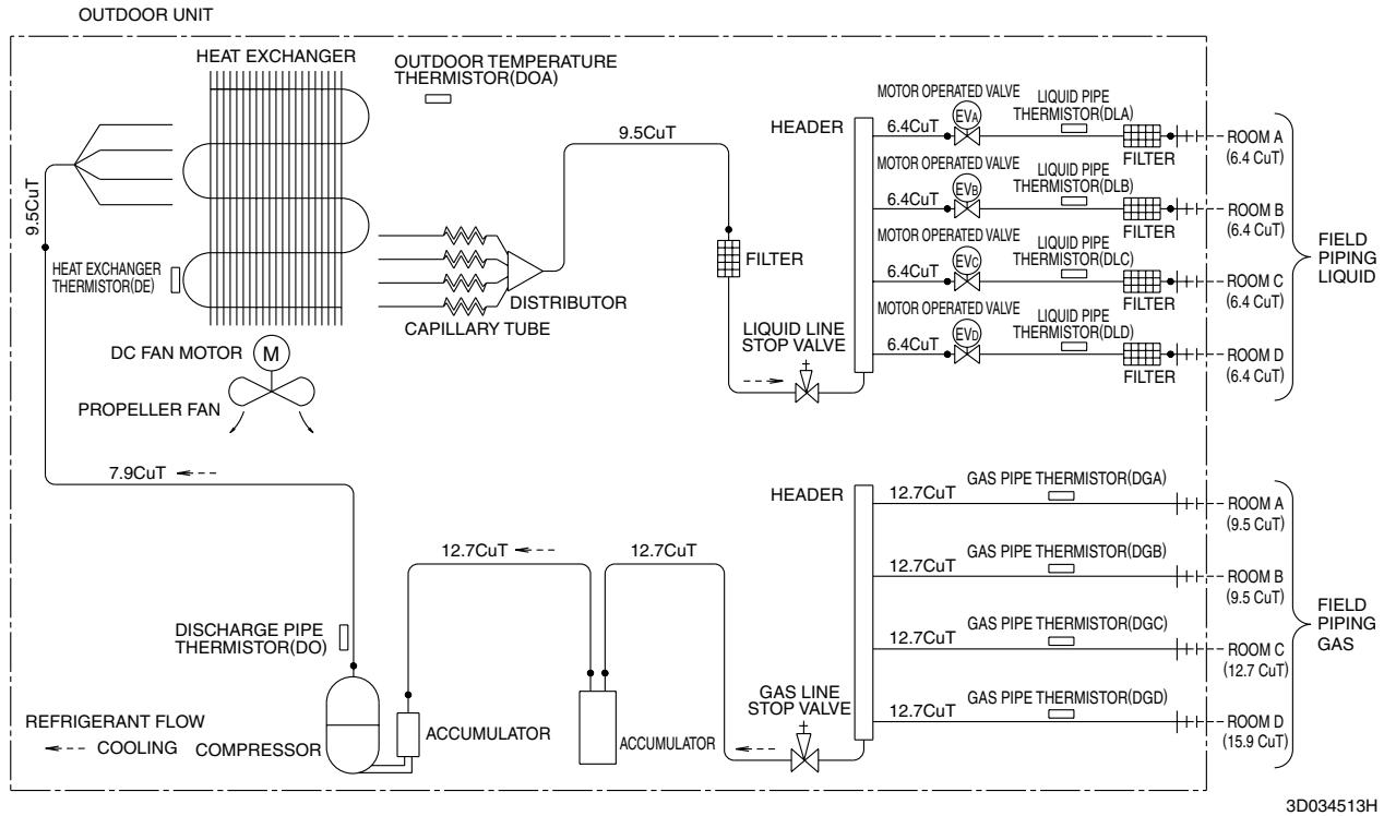
flowchart
graph TD
    A["OUTDOOR UNIT"] --> B["HEAT EXCHANGER"]
    B --> C["9.5CuT"]
    B --> D["Distributor"]
    D --> E["CAPILLARY TUBE"]
    E --> F["9.5CuT"]
    F --> G["FILTER"]
    G --> H["Liquid Line Stop Valve"]
    H --> I["HEADER"]
    I --> J["MOTOR OPERATED VALVE EVA"]
    I --> K["LIQUID PIPE THERMISTOR(DLA)"]
    I --> L["FILTER"]
    L --> M["ROOM A (6.4 CuT)"]
    L --> N["ROOM B (6.4 CuT)"]
    L --> O["ROOM C (6.4 CuT)"]
    L --> P["ROOM D (6.4 CuT)"]

    Q["PROPELLER FAN"] --> R["DC FAN MOTOR M"]
    R --> S["7.9CuT ← --"]

    T["DISCHARGE PIPE THERMISTOR(DO)"] --> U["12.7CuT ← --"]
    U --> V["ACCUMULATOR"]
    V --> W["12.7CuT ← --"]

    X["REFRIGERANT FLOW"] --> Y["COOLING COMPRESSOR"]

    Z["FIELD PIPING LIQUID"] --> AA["12.7CuT ← --"]
    AA --> AB["GAS PIPE THERMISTOR(DGA)"]
    AB --> AC["ROOM A (9.5 CuT)"]
    AB --> AD["ROOM B (9.5 CuT)"]
    AB --> AE["ROOM C (12.7 CuT)"]
    AB --> AF["ROOM D (15.9 CuT)"]

    AG["3D034513H"] --> AH["FIELD PIPING GAS"]
5MKS90E2V3B
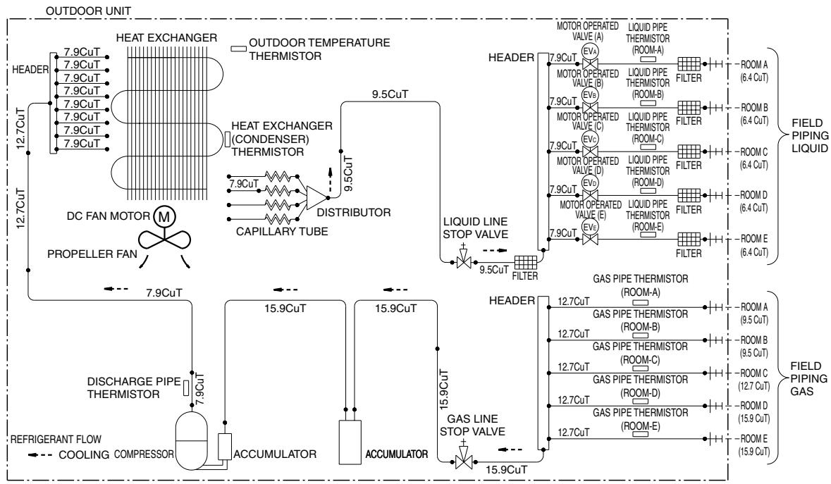
flowchart
graph TD
    A["OUTDOOR UNIT"] --> B["HEAT EXCHANGER"]
    A --> C["OUTDOOR TEMPERATURE THERMISTOR"]
    B --> D["7.9CuT"]
    B --> E["7.9CuT"]
    B --> F["7.9CuT"]
    B --> G["7.9CuT"]
    B --> H["7.9CuT"]
    B --> I["7.9CuT"]
    B --> J["7.9CuT"]
    B --> K["7.9CuT"]
    B --> L["12.7CuT"]
    L --> M["DC FAN MOTOR M"]
    M --> N["PROPELLER FAN"]
    N --> O["DISCHARGE PIPE THERMISTOR"]
    O --> P["REFRIGERANT FLOW COOLING COMPRESSOR"]
    P --> Q["ACCUMULATOR"]
    Q --> R["15.9CuT"]
    R --> S["ACCUMULATOR"]
    S --> T["15.9CuT"]
    T --> U["15.9CuT"]
    U --> V["15.9CuT"]
    V --> W["15.9CuT"]
    W --> X["15.9CuT"]
    X --> Y["15.9CuT"]
    Y --> Z["15.9CuT"]
    Z --> AA["15.9CuT"]
    AA --> AB["15.9CuT"]
    AB --> AC["15.9CuT"]

    subgraph HEAD
        AD["7.9CuT"] --> AE["MOTOR OPERATED VALVE (A)"]
        AE --> AF["MOTOR OPERATED VALVE (B)"]
        AF --> AG["MOTOR OPERATED VALVE (C)"]
        AG --> AH["MOTOR OPERATED VALVE (D)"]
        AH --> AI["MOTOR OPERATED VALVE (E)"]
        AI --> AJ["MOTOR OPERATED VALVE (F)"]
        AJ --> AK["MOTOR OPERATED VALVE (G)"]
        AK --> AL["MOTOR OPERATED VALVE (H)"]
        AL --> AM["MOTOR OPERATED VALVE (I)"]
        AM --> AN["MOTOR OPERATED VALVE (J)"]
        AN --> AO["MOTOR OPERATED VALVE (K)"]
        AO --> AP["MOTOR OPERATED VALVE (L)"]
        AP --> AQ["MOTOR OPERATED VALVE (M)"]
        AQ --> AR["MOTOR OPERATED VALVE (N)"]
        AR --> AS["MOTOR OPERATED VALVE (O)"]
        AS --> AT["MOTOR OPERATED VALVE (P)"]
        AT --> AU["MOTOR OPERATED VALVE (Q)"]
        AU --> AV["MOTOR OPERATED VALVE (R)"]
        AV --> AW["MOTOR OPERATED VALVE (S)"]
        AW --> AX["MOTOR OPERATED VALVE (T)"]
        AX --> AY["MOTOR OPERATED VALVE (U)"]
        AY --> AZ["MOTOR OPERATED VALVE (V)"]
        AZ --> BA["MOTOR OPERATED VALVE (W)"]
        BA --> BB["MOTOR OPERATED VALVE (X)"]
        BB --> BC["MOTOR OPERATED VALVE (Y)"]
        BC --> BD["MOTOR OPERATED VALVE (Z)"]
        BD --> BE["MOTOR OPERATED VALVE (W)"]
        BE --> BF["MOTOR OPERATED VALVE (X)"]
        BF --> BG["MOTOR OPERATED VALVE (Y)"]
        BG --> BH["MOTOR OPERATED VALVE (Z)"]
        BH --> BI["MOTOR OPERATED VALVE (W)"]
        BI --> BJ["MOTOR OPERATED VALVE (X)"]
        BJ --> BK["MOTOR OPERATED VALVE (Y)"]
        BK --> BL["MOTOR OPERATED VALVE (Z)"]
        BL --> BM["MOTOR OPERATED VALVE (W)"]
        BM --> BN["MOTOR OPERATED VALVE (X)"]
        BN --> BO["MOTOR OPERATED VALVE (Y)"]
        BO --> BP["MOTOR OPERATED VALVE (Z)"]
        BP --> BQ["MOTOR OPERATED VALVE (W)"]
        BQ --> BR["MOTOR OPERATED VALVE (X)"]
        BR --> BS["MOTOR OPERATED VALVE (Y)"]
        BS --> BT["MOTOR OPERATED VALVE (Z)"]
        BT --> BU["MOTOR OPERATED VALVE (W)"]
        BU --> BV["MOTOR OPERATED VALVE (X)"]
        BV --> BW["MOTOR OPERATED VALVE (Y)"]
        BW --> BX["MOTOR OPERATED VALVE (Z)"]
        BX --> BY["MOTOR OPERATED VALVE (W)"]
        BY --> BZ["MOTOR OPERATED VALVE (X)"]
        BZ --> CA["MOTOR OPERATED VALVE (Y)"]
        CA --> CB["MOTOR OPERATED VALVE (Z)"]
        CB --> CC["MOTOR OPERATED VALVE (W)"]
        CC --> CD["MOTOR OPERATED VALVE (X)"]
        CD --> CE["MOTOR OPERATED VALVE (Y)"]
        CE --> CF["MOTOR OPERATED VALVE (Z)"]
        CF --> CG["MOTOR OPERATED VALVE (W)"]
        AG --> CH["7.9CuT"]
        CH --> CI["MOTOR OPERATED VALVE (A)"]
        CH --> CJ["MOTOR OPERATED VALVE (B)"]
        CH --> CK["MOTOR OPERATED VALVE (C)"]
        CH --> CL["MOTOR OPERATED VALVE (D)"]
        CH --> CM["MOTOR OPERATED VALVE (E)"]
        CH --> CN["MOTOR OPERATED VALVE (F)"]
        CH --> CO["MOTOR OPERATED VALVE (G)"]
        CH --> CP["MOTOR OPERATED VALVE (H)"]
        CH --> CQ["MOTOR OPERATED VALVE (I)"]
        CH --> CR["MOTOR OPERATED VALVE (J)"]
        CH --> CS["MOTOR OPERATED VALVE (K)"]
        CH --> CT["MOTOR OPERATED VALVE (L)"]
        CH --> CU["MOTOR OPERATED VALVE (M)"]
        CH --> CV["MOTOR OPERATED VALVE (N)"]
        CH --> CW["MOTOR OPERATED VALVE (O)"]
        CH --> CX["MOTOR OPERATED VALVE (P)"]
        CH --> CY["MOTOR OPERATED VALVE (Q)"]
        CH --> CZ["MOTOR OPERATED VALVE (R)"]
        CH --> DA["MOTOR OPERATED VALVE (S)"]
        CH --> DB["MOTOR OPERATED VALVE (T)"]
        CH --> DC["MOTOR OPERATED VALVE (U)"]
        CH --> DD["MOTOR OPERATED VALVE (V)"]
        CH --> DE["MOTOR OPERATED VALVE (W)"]
        CH --> DF["MOTOR OPERATED VALVE (X)"]
        CH --> DG["MOTOR OPERATED VALVE (Y)"]
        CH --> DH["MOTOR OPERATED VALVE (Z)"]
3D051938
1.1.2 Heat Pump
3MXS40K2V1B
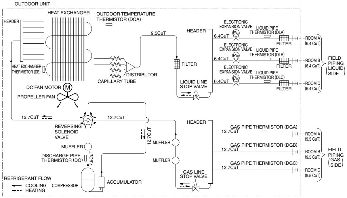
flowchart
graph TD
    A["HEAT EXCHANGER"] --> B["OUTDOOR TEMPERATURE THERMISTOR (DOA)"]
    B --> C["CAPILLARY TUBE"]
    C --> D["DISTRIBUTOR"]
    D --> E["9.5CuT"]
    E --> F["HEADER"]
    F --> G["ELECTRONIC EXPANSION VALVE 6.4CuT"]
    G --> H["FILTER"]
    H --> I["LIQUID LINE STOP VALVE"]
    I --> J["EVO"]
    J --> K["HEATER"]
    K --> L["HEATER"]
    L --> M["HEATER"]
    M --> N["FILTER"]
    N --> O["HEATER"]
    O --> P["FILTER"]
    P --> Q["FILTER"]
    Q --> R["FILTER"]
    R --> S["FILTER"]
    S --> T["FILTER"]
    T --> U["FILTER"]
    U --> V["FILTER"]
    V --> W["FILTER"]
    W --> X["FILTER"]
    X --> Y["FILTER"]
    Y --> Z["FILTER"]
    Z --> AA["FILTER"]
    AA --> AB["FILTER"]
    AB --> AC["FILTER"]
    AC --> AD["FILTER"]
    AD --> AE["FILTER"]
    AE --> AF["FILTER"]
    AF --> AG["FILTER"]
    AG --> AH["FILTER"]
    AH --> AI["FILTER"]
    AI --> AJ["FILTER"]
    AJ --> AK["FILTER"]
    AK --> AL["FILTER"]
    AL --> AM["FILTER"]
    AM --> AN["FILTER"]
    AN --> AO["FILTER"]
    AO --> AP["FILTER"]
    AP --> AQ["FILTER"]
    AQ --> AR["FILTER"]
    AR --> AS["FILTER"]
    AS --> AT["FILTER"]
    AT --> AU["FILTER"]
    AU --> AV["FILTER"]
    AV --> AW["FILTER"]
    AW --> AX["FILTER"]
    AX --> AY["FILTER"]
    AY --> AZ["FILTER"]
    AZ --> BA["FILTER"]
    BA --> BB["FILTER"]
    BB --> BC["FILTER"]
    BC --> BD["FILTER"]
    BD --> BE["FILTER"]
    BE --> BF["FILTER"]
    BF --> BG["FILTER"]
    BG --> BH["FILTER"]
    BH --> BI["FILTER"]
    BI --> BJ["FILTER"]
    BJ --> BK["FILTER"]
    BK --> BL["FILTER"]
    BL --> BM["FILTER"]
    BM --> BN["FILTER"]
    BN --> BO["FILTER"]
    BO --> BP["FILTER"]
    BP --> BQ["FILTER"]
    BQ --> BR["FILTER"]
    BR --> BS["FILTER"]
    BS --> BT["FILTER"]
    BT --> BU["FILTER"]
    BU --> BV["FILTER"]
    BV --> BW["FILTER"]
    BW --> BX["FILTER"]
    BX --> BY["FILTER"]
    BY --> BZ["FILTER"]
    BZ --> CA["FILTER"]
    CA --> CB["FILTER"]
    CB --> CC["FILTER"]
    CC --> CD["FILTER"]
    CD --> CE["FILTER"]
    CE --> CF["FILTER"]
    CF --> CG["FILTER"]
    CG --> CH["FILTER"]
    CH --> CI["FILTER"]
    CI --> CJ["FILTER"]
    CJ --> CK["FILTER"]
    CK --> CR["FILTER"]
    CR --> CS["FILTER"]
    CS --> CT["FILTER"]
    CT --> CU["FILTER"]
    CU --> CV["FILTER"]
    CV --> CW["FILTER"]
    CW --> CX["FILTER"]
    CX --> CY["FILTER"]
    CY --> CZ["FILTER"]
    CZ --> DA["FILTER"]
    DA --> DB["FILTER"]
    DB --> DC["FILTER"]
    DC --> DD["FILTER"]
    DD --> DEF["GAS PIPE THERMISTOR (DGC)"]
    DEG["GAS PIPE THERMISTOR (DGB)"]
    DEH["GAS PIPE THERMISTOR (DCA)"]
    DEI["GAS PIPE THERMISTOR (DGA)"]
    DEJ["GAS PIPE THERMISTOR (DGC)"]
    DEK["GAS PIPE THERMISTOR (DGA)"]
    DE_L["GAS PIPE THERMISTOR (DGA)"]
    DE_M["GAS PIPE THERMISTOR (DGA)"]
    DE_N["GAS PIPE THERMISTOR (DGA)"]
    DE_O["GAS PIPE THERMISTOR (DGA)"]
    DE_P["GAS PIPE THERMISTOR (DGA)"]
    DE_Q["GAS PIPE THERMISTOR (DGA)"]
    DE_R["GAS PIPE THERMISTOR (DGA)"]
    DE_S["GAS PIPE THERMISTOR (DGA)"]
    DE_T["GAS PIPE THERMISTOR (DGA)"]
    DE_U["GAS PIPE THERMISTOR (DGA)"]
    DE_V["GAS PIPE THERMISTOR (DGA)"]
    DE_W["GAS PIPE THERMISTOR (DGA)"]
    DE_X["GAS PIPE THERMISTOR (DGA)"]
    DE_Y["GAS PIPE THERMISTOR (DGA)"]
    DE_Z["GAS PIPE THERMISTOR (DGA)"]
    DE_AA["GAS PIPE THERMISTOR (DGA)"]
    DE_AB["GAS PIPE THERMISTOR (DGA)"]
    DE_AC["GAS PIPE THERMISTOR (DGA)"]
    DE_AD["GAS PIPE THERMISTOR (DGA)"]
    DE_AE["GAS PIPE THERMISTOR (DGA)"]
    DE_AF["GAS PIPE THERMISTOR (DGA)"]
    DE_AG["GAS PIPE THERMISTOR (DGA)"]
    DE_AH["GAS PIPE THERMISTOR (DGA)"]
    DE_AI["GAS PIPE THERMISTOR (DGA)"]
    DE_AJ["GAS PIPE THERMISTOR (DGA)"]
    DE_AK["GAS PIPE THERMISTOR (DGA)"]
    DE_AL["GAS PIPE THERMISTOR (DGA)"]
    DE_AM["GAS PIPE THERMISTOR (DGA)"]
    DE_AN["GAS PIPE THERMISTOR (DGA)"]
    DE_AO["GAS PIPE THERMISTOR (DGA)"]
    DE_AP["GAS PIPE THERMISTOR (DGA)"]
    DE_AQ["GAS PIPE THERMISTOR (DGA)"]
    DE_AR["GAS PIPE THERMISTOR (DGA)"]
    DE_AS["GAS PIPE THERMISTOR (DGA)"]
    DE_ATG["GAS PIPE THERMISTOR (DGA)"]
    DE_AUG["GAS PIPE THERMISTOR (DGA)"]
    DE_AVG["GAS PIPE THERMISTOR (DGA)"]
    DE_AWG["GAS PIPE THERMISTOR (DGA)"]
    DE_AXG["GAS PIPE THERMISTOR (DGA)"]
    DE_AYG["GAS PIPE THERMISTOR (DGA)"]
    DE_AZG["GAS PIPE THERMISTOR (DGA)"]
    DE_BAAY["GAS PIPE THERMISTOR (DGA)"]
    DE_BBAY["GAS PIPE THERMISTOR (DGA)"]
    DE_BCAY["GAS PIPE THERMISTOR (DGA)"]
    DE_CAYG["GAS PIPE THERMISTOR (DGA)"]
    DE_CEAYG["GAS PIPE THERMISTOR (DGA)"]
    DE CEAYG
    CEAYG
    CEAYG
    CEAYG
    CEAYG
    CEAYG
    CEAYG
    CEAYG
    CEAYG
    CEAYG
    CEAYG
    CEAYG
    CEAYG
    CEAYG
    CEAYG
    CEAYG
    CEAYG
    CEAYG
    CEAYG
    CEAYG
    CEAYG

    subgraph OUTDOOR UNIT
        direction TB
        A1["HEADER"]
        A2["HEAT EXCHANGER"]
        A3["HEAT EXCHANGER"]
        A4["HEAT EXCHANGER"]
        A5["HEAT EXCHANGER"]
        A6["HEAT EXCHANGER"]
        A7["HEAT EXCHANGER"]
        A8["HEAT EXCHANGER"]
        A9["HEAT EXCHANGER"]
        A10["HEAT EXCHANGER"]
        A11["HEAT EXCHANGER"]
        A12["HEAT EXCHANGER"]
        A13["HEAT EXCHANGER"]
        A14["HEAT EXCHANGER"]
        A15["HEAT EXCHANGER"]
        A16["HEAT EXCHANGER"]
        A17["HEAT EXCHANGER"]
        A18["HEAT EXCHANGER"]
        A19["HEAT EXCHANGER"]
        A20["HEAT EXCHANGER"]
        A21["HEAT EXCHANGER"]
        A22["HEAT EXCHANGER"]
        A23["HEAT EXCHANGER"]
        A24["HEAT EXCHANGER"]
        A25["HEAT EXCHANGER"]
        A26["HEAT EXCHANGER"]
        A27["HEAT EXCHANGER"]
        A28["HEAT EXCHANGER"]
        A29["HEAT EXCHANGER"]
        A30["HEAT EXCHANGER"]
        A31["HEAT EXCHANGER"]
        A32["HEAT EXCHANGER"]
        A33["HEAT EXCHANGER"]
        A34["HEAT EXCHANGER"]
        A35["HEAT EXCHANGER"]
        A36["HEAT EXCHANGER"]
        A37["HEAT EXCHANGER"]
        A38["HEAT EXCHANGER"]
        A39["HEAT EXCHANGER"]
        A40["HEAT EXCHANGER"]
        A41["HEAT EXCHANGER"]
        A42["HEAT EXCHANGER"]
        A43["HEAT EXCHANGER"]
        A44["HEAT EXCHANGER"]
        A45["HEAT EXCHANGER"]
        A46["HEAT EXCHANGER"]
        A47["HEAT EXCHANGER"]
        A48["HEAT EXCHANGER"]
        A49["HEAT EXCHANGER"]
        A50["HEAT EXCHANGER"]
        A51["HEAT EXCHANGER"]
        A52["HEAT EXCHANGER"]
        A53["HEAT EXCHANGER"]
        A54["HEAT EXCHANGER"]
        A55["HEAT EXCHANGER"]
        A56["HEAT EXCHANGER"]
        A57["HEAT EXCHANGER"]
        A58["HEAT EXCHANGER"]
        A59["HEAT EXCHANGER"]
        A60["HEAT EXCHANGER"]
        A61["HEAT EXCHANGER"]
        A62["HEAT EXCHANGER"]
        A63["HEAT EXCHANGER"]
        A64["HEAT EXCHANGER"]
        A65["HEAT EXCHANGER"]
        A66["HEAT EXCHANGER"]
        A67["HEAT EXCHANGER"]
        A68["HEAT EXCHANGER"]
        A69["HEAT EXCHANGER"]
        A70["HEAT EXCHANGER"]
        A71["HEAT EXCHANGER"]
        A72["HEAT EXCHANGER"]
        A73["HEAT EXCHANGER"]
        A74["HEAT EXCHANGER"]
        A75["HEAT EXCHANGER"]
        A76["HEAT EXCHANGER"]
        A77["HEAT EXCHANGER"]
        A78["HEAT EXCHANGER"]
        A79["HEAT EXCHANGER"]
        A80["HEAT EXCHANGER"]
        A81["HEAT EXCHANGER"]
        A82["HEAT EXCHANGER"]
        A83["HEAT EXCHANGER"]
        A84["HEAT EXCHANGER"]
        A85["HEAT EXCHANGER"]
        A86["HEAT EXCHANGER"]
        A87["HEAT EXCHANGER"]
        A88["HEAT EXCHANGER"]
        A89["HEAT EXCHANGER"]
        A90["HEAT EXCHANGER"]
        A91["HEAT EXCHANGER"]
        A92["HEAT EXCHANGER"]
        A93["HEAT EXCHANGER"]
        A94["HEAT EXCHANGER"]
        A95["HEAT EXCHANGER"]
        A96["HEAT EXCHANGER"]
        A97["HEAT EXCHANGER"]
        A98["HEAT EXCHANGER"]
        A99["HEAT EXCHANGER"]
        AZ["HOPPER FAN FAN PROPELLER FAN 12.7CuT"] & AB["HOPPER FAN PROPeller FAN 12.7CuT"]
3D073394
3MXS52E3V1B

flowchart
graph TD
    A["OUTDOOR UNIT"] --> B["HEAT EXCHANGER"]
    B --> C["COOLING"]
    B --> D["HEATING"]
    B --> E["HEATER"]
    E --> F["DISTRIBUTOR"]
    F --> G["CAPILLARY TUBE"]
    G --> H["9.5CuT"]
    H --> I["FILTER"]
    I --> J["LIQUID LINE STOP VALVE"]
    J --> K["REVERSING SOLENOID VALVE"]
    K --> L["MUFFLER"]
    L --> M["DISCHARGE PIPE THERMISTOR (DO)"]
    M --> N["12.7CuT"]
    N --> O["ACCUMULATOR"]
    O --> P["12.7CuT"]
    P --> Q["HEATER"]
    Q --> R["GAS LINE STOP VALVE"]
    R --> S["MUFFLER"]
    S --> T["12.7CuT"]
    T --> U["HEATER"]
    U --> V["GAS PIPE THERMISTOR (DGA)"]
    V --> W["12.7CuT"]
    W --> X["HEATER"]
    X --> Y["GAS PIPE THERMISTOR (DGB)"]
    Y --> Z["12.7CuT"]
    Z --> AA["HEATER"]
    AA --> AB["GAS PIPE THERMISTOR (DGC)"]
    AB --> AC["12.7CuT"]
    AC --> AD["HEATER"]
    AD --> AE["GAS PIPE THERMISTOR (DLA)"]
    AE --> AF["6.4CuT"]
    AF --> AG["EVA"]
    AG --> AH["ELTRIC EXPANSION VALVE"]
    AH --> AI["FILTER"]
    AI --> AJ["6.4CuT"]
    AJ --> AK["EVA"]
    AK --> AL["ELTRIC EXPANSION VALVE"]
    AL --> AM["FILTER"]
    AM --> AN["EVA"]
    AN --> AO["ELTRIC EXPANSION VALVE"]
    AO --> AP["FILTER"]
    AP --> AQ["EVA"]
    AQ --> AR["ELTRIC EXPANSION VALVE"]
    AR --> AS["FILTER"]
    AS --> AT["EVA"]
    AT --> AU["ELTRIC EXPANSION VALVE"]
    AU --> AV["FILTER"]
    AV --> AW["EVA"]
    AW --> AX["ELTRIC EXPANSION VALVE"]
    AX --> AY["FILTER"]
    AY --> AZ["EVA"]
    AZ --> BA["ELTRIC EXPANSION VALVE"]
    BA --> BB["FILTER"]
    BB --> BC["EVA"]
    BC --> BD["ELTRIC EXPANSION VALVE"]
    BD --> BE["FILTER"]
    BE --> BF["EVA"]
    BF --> BG["ELTRIC EXPANSION VALVE"]
    BG --> BH["FILTER"]
    BH --> BI["EVA"]
    BI --> BJ["ELTRIC EXPANSION VALVE"]
    BJ --> BK["FILTER"]
    BK --> BL["EVA"]
    BL --> BM["ELTRIC EXPANSION VALVE"]
    BM --> BN["FILTER"]
    BN --> BO["EVA"]
    BO --> BP["ELTRIC EXPANSION VALVE"]
    BP --> BQ["FILTER"]
    BQ --> BR["EVA"]
    BR --> BS["ELTRIC EXPANSION VALVE"]
    BS --> BT["FILTER"]
    BT --> BU["EVA"]
    BU --> BV["ELTRIC EXPANSION VALVE"]
3D052055D
3MXS68G2V1B
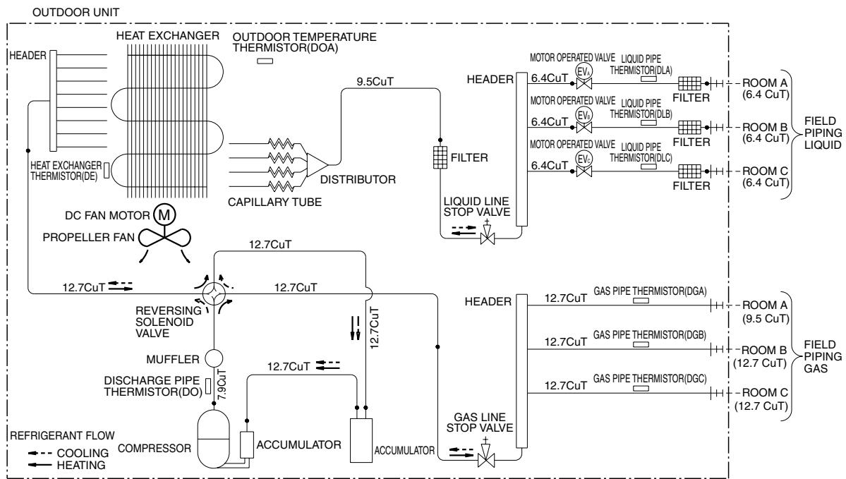
flowchart
graph TD
    A["HEAT EXCHANGER"] --> B["OUTDOOR TEMPERATURE THERMISTOR(DOA)"]
    B --> C["DISTRIBUTOR"]
    C --> D["CAPILLARY TUBE"]
    D --> E["HEADER"]
    E --> F["MOTOR OPERATED VALVE"]
    F --> G["LIQUID PIPE THERMISTOR(DLA)"]
    G --> H["FILTER"]
    H --> I["ROOM A (6.4 CuT)"]
    H --> J["ROOM B (6.4 CuT)"]
    H --> K["ROOM C (6.4 CuT)"]
    L["DC FAN MOTOR M PROPELLER FAN"] --> M["12.7CuT"]
    M --> N["REVERSING SOLENOID VALVE"]
    N --> O["MUFFLER"]
    O --> P["DISCHARGE PIPE THERMISTOR(DO)"]
    P --> Q["7.9CuT"]
    Q --> R["ACCCUMULATOR"]
    R --> S["ACCUMULATOR"]
    S --> T["HEADER"]
    T --> U["GAS PIPE THERMISTOR(DGA)"]
    U --> V["FILTER"]
    V --> W["ROOM A (9.5 CuT)"]
    V --> X["ROOM B (12.7 CuT)"]
    V --> Y["ROOM C (12.7 CuT)"]
    Z["REFRIGERANT FLOW"] --> AA["COOLING"]
    Z --> AB["HEATING"]
    AC["COOLING"] --> AD["HEATER"]
    AE["HEATER"] --> AF["FILTER"]
    AG["FILTER"] --> AH["MOBIC THERMISTOR(DLB)"]
    AI["MOBIC THERMISTOR(DLC)"] --> AJ["FILTER"]
    AK["MOBIC THERMISTOR(DGC)"] --> AL["FILTER"]
    AM["FILTER"] --> AN["FIELD PIPING LIQUID"]
    AO["FIELD PIPING GAS"] --> AP["FIELD PIPING LIQUID"]
3D058888
4MXS68F2V1B
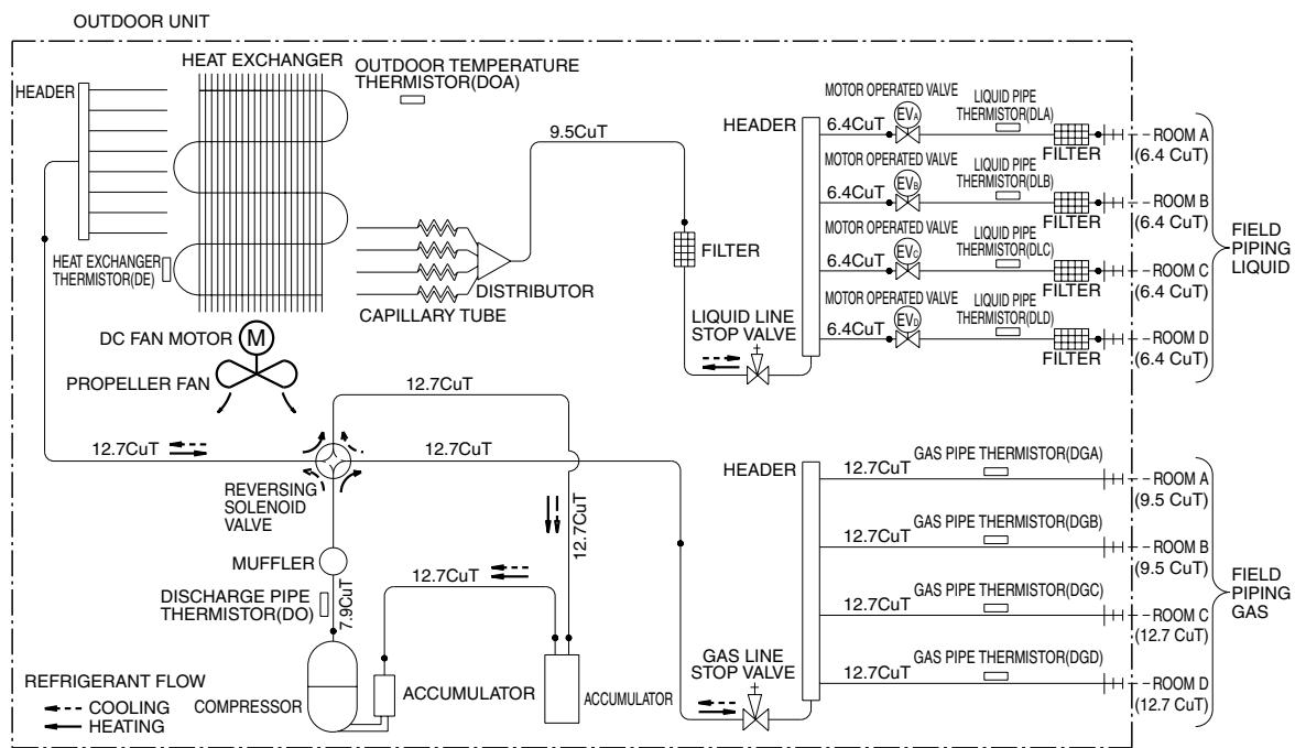
flowchart
graph TD
    A["HEAT EXCHANGER"] --> B["OUTDOOR TEMPERATURE THERMISTOR(DOA)"]
    B --> C["CAPILLARY TUBE"]
    C --> D["DISTRIBUTOR"]
    D --> E["9.5CuT"]
    E --> F["HEADER"]
    F --> G["MOTOR OPERATED VALVE"]
    G --> H["6.4CuT"]
    H --> I["EV3"]
    I --> J["LIQUID PIPE THERMISTOR(DLA)"]
    J --> K["FILTER"]
    K --> L["-ROOM A (6.4 CuT)"]
    K --> M["LOWER B (6.4 CuT)"]
    K --> N["FILTER"]
    N --> O["-ROOM C (6.4 CuT)"]
    N --> P["FILTER"]
    P --> Q["-ROOM D (6.4 CuT)"]
    P --> R["FILTER"]
    R --> S["-ROOM A (9.5 CuT)"]
    R --> T["LOWER B (9.5 CuT)"]
    R --> U["FILTER"]
    U --> V["-ROOM C (12.7 CuT)"]
    U --> W["FILTER"]
    W --> X["-ROOM D (12.7 CuT)"]

    A --> Y["HEAT EXCHANGER THERMISTOR(DE)"]
    Y --> Z["DC FAN MOTOR M"]
    Z --> AA["PROPELLER FAN"]
    AA --> AB["12.7CuT"]
    AB --> AC["REVERSING SOLENOID VALVE"]
    AC --> AD["MUFFLER"]
    AD --> AE["DISCHARGE PIPE THERMISTOR(DO)"]
    AE --> AF["7.9CuT"]
    AF --> AG["ACCUMULATOR"]
    AG --> AH["12.7CuT"]
    AH --> AI["12.7CuT"]
    AI --> AJ["12.7CuT"]
    AJ --> AK["12.7CuT"]
    AK --> AL["12.7CuT"]

    subgraph OUTDOOR UNIT
        direction TB
        A
        B
        C
        D
        E
        F
        G
        H
        I
        J
        K
        L
        M
        N
        O
        P
        Q
        R
        S
        T
        U
        V
        W
        X
        Y
        Z
        AA
        AB
        AC
        AD
        AE
        AF
        AG
        AH
        AI
        AJ
        AK
        AL
        AM
        AN
        AO
        AP
        AQ
        AR
        AS
        AT
        AU
        AV
        AW
        AX
        AY
        AZ
        BA
        BB
        BC
        BD
        BE
        BF
        BG
        BH
        BI
        BJ
        BK
        BL
        BM
        BN
        BO
        BP
        BPB
        BPB
        BPB
        BPB
    end

    %% Diagrammatic elements for each component of the circuit.
    %% Legend:
    direction TB: 0, 1, 2, 3, 4, 5, 6, 7, 8, 9, 10, 11, 12, 13, 14, 15, 16, 17, 18, 19, 20, 21, 22, 23, 24, 25, 26, 27, 28, 29, 30, 31, 32, 33, 34, 35, 36, 37, 38, 39, 40, 41, 42, 43, 44, 45, 46, 47, 48, 49, 50, 51, 52, 53, 54, 55, 56, 57, 58, 59, 60, 61, 62, 63, 64, 65, 66, 67, 68, 69, 70, 71, 72, 73, 74, 75, 76, 77, 78, 79, 80, 81, 82, 83, 84, 85, 86, 87, 88, 89, 90, 91, 92, 93, 94, 95, 96, 97, 98, 99, 100,
    %% Annotations on main components and interfaces.
3D055041
4MXS80E2V3B
OUTDOOR UNIT
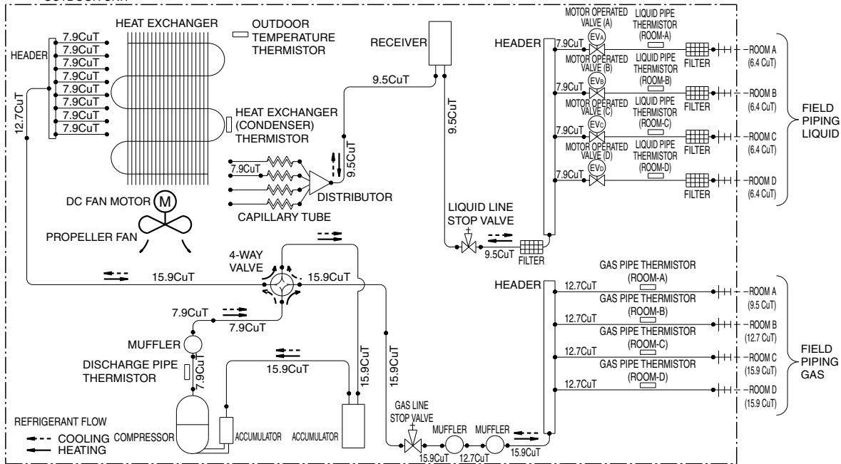
flowchart
graph TD
    A["HEAT EXCHANGER"] --> B["OUTDOOR TEMPERATURE THERMISTOR"]
    B --> C["RECEIVER"]
    C --> D["HEAT EXCHANGER (CONDenser) THERMISTOR"]
    D --> E["DISTRIBUTOR"]
    E --> F["CAPILLARY TUBE"]
    F --> G["4-WAY VALVE"]
    G --> H["MUFFLER"]
    H --> I["DISCHARGE PIPE THERMISTOR"]
    I --> J["REFRIGERANT FLOW"]
    J --> K["COOLING COMPRESSOR"]
    J --> L["HEATING"]
    M["DC FAN MOTOR"] --> N["PROPELLER FAN"]
    N --> O["15.9CuT"]
    O --> P["7.9CuT"]
    P --> Q["7.9CuT"]
    Q --> R["7.9CuT"]
    R --> S["7.9CuT"]
    S --> T["7.9CuT"]
    T --> U["7.9CuT"]
    U --> V["7.9CuT"]
    V --> W["7.9CuT"]
    W --> X["7.9CuT"]
    X --> Y["7.9CuT"]
    Y --> Z["7.9CuT"]
    Z --> AA["7.9CuT"]
    AA --> AB["7.9CuT"]
    AB --> AC["7.9CuT"]
    AC --> AD["7.9CuT"]
    AD --> AE["7.9CuT"]
    AE --> AF["7.9CuT"]
    AF --> AG["7.9CuT"]
    AG --> AH["7.9CuT"]
    AH --> AI["7.9CuT"]
    AI --> AJ["7.9CuT"]
    AJ --> AK["7.9CuT"]
    AK --> AL["7.9CuT"]
    AL --> AM["7.9CuT"]
    AM --> AN["7.9CuT"]
    AN --> AO["7.9CuT"]
    AO --> AP["7.9CuT"]
    AP --> AQ["7.9CuT"]
    AQ --> AR["7.9CuT"]
    AR --> AS["7.9CuT"]
    AS --> AT["7.9CuT"]
    AT --> AU["7.9CuT"]
    AU --> AV["7.9CuT"]
    AV --> AW["7.9CuT"]
    AW --> AX["7.9CuT"]
    AX --> AY["7.9CuT"]
    AY --> AZ["7.9CuT"]
    AZ --> BA["7.9CuT"]
    BA --> BB["7.9CuT"]
    BB --> BC["7.9CuT"]
    BC --> BD["7.9CuT"]
    BD --> BE["7.9CuT"]
    BE --> BF["7.9CuT"]
    BF --> BG["7.9CuT"]
    BG --> BH["7.9CuT"]
    BH --> BI["7.9CuT"]
    BI --> BJ["7.9CuT"]
    BJ --> BK["7.9CuT"]
    BK --> BL["7.9CuT"]
    BL --> BM["7.9CuT"]
    BM --> BN["7.9CuT"]
    BN --> BO["7.9CuT"]
    BO --> BP["7.9CuT"]
    BP --> BQ["7.9CuT"]
    BQ --> BR["7.9CuT"]
    BR --> BS["7.9CuT"]
    BS --> BT["7.9CuT"]
    BT --> BU["7.9CuT"]
    BU --> BV["7.9CuT"]
    BV --> BW["7.9CuT"]
    BW --> BX["7.9CuT"]
    BX --> BY["7.9CuT"]
    BY --> BZ["7.9CuT"]
3D051937E
5MXS90E2V3B
OUTDOOR UNIT
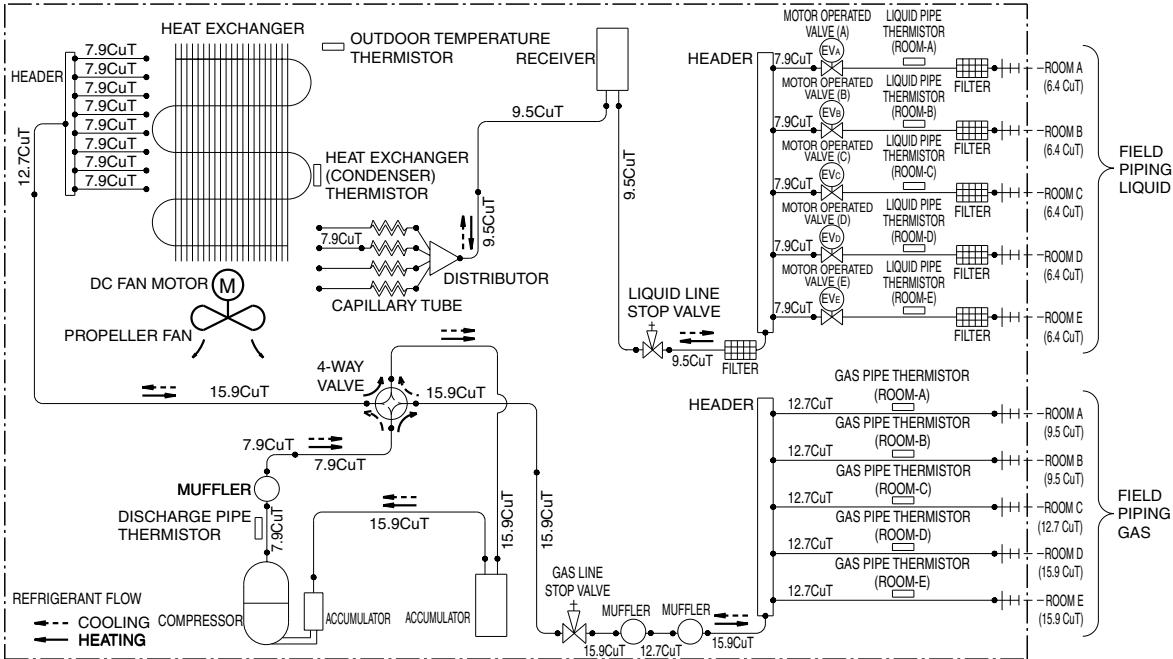
flowchart
graph TD
    A["HEAT EXCHANGER"] --> B["OUTDOOR TEMPERATURE THERMISTOR"]
    B --> C["RECEIVER"]
    C --> D["HEAT EXCHANGER (CONDenser) THERMISTOR"]
    D --> E["DISTRIBUTOR"]
    E --> F["CAPILLARY TUBE"]
    F --> G["4-WAY VALVE"]
    G --> H["MUFFLER"]
    H --> I["DISCHARGE PIPE THERMISTOR"]
    I --> J["REFRIGERANT FLOW"]
    J --> K["COOLING COMPRESSOR"]
    J --> L["HEATING"]
    M["DC FAN MOTOR"] --> N["PROPELLER FAN"]
    N --> O["15.9CuT"]
    O --> P["7.9CuT"]
    P --> Q["7.9CuT"]
    Q --> R["7.9CuT"]
    R --> S["7.9CuT"]
    S --> T["7.9CuT"]
    T --> U["7.9CuT"]
    U --> V["7.9CuT"]
    V --> W["7.9CuT"]
    W --> X["7.9CuT"]
    X --> Y["7.9CuT"]
    Y --> Z["7.9CuT"]
    Z --> AA["7.9CuT"]
    AA --> AB["7.9CuT"]
    AB --> AC["7.9CuT"]
    AC --> AD["7.9CuT"]
    AD --> AE["7.9CuT"]
    AE --> AF["7.9CuT"]
    AF --> AG["7.9CuT"]
    AG --> AH["7.9CuT"]
    AH --> AI["7.9CuT"]
    AI --> AJ["7.9CuT"]
    AJ --> AK["7.9CuT"]
    AK --> AL["7.9CuT"]
    AL --> AM["7.9CuT"]
    AM --> AN["7.9CuT"]
    AN --> AO["7.9CuT"]
    AO --> AP["7.9CuT"]
    AP --> AQ["7.9CuT"]
    AQ --> AR["7.9CuT"]
    AR --> AS["7.9CuT"]
    AS --> AT["7.9CuT"]
    AT --> AU["7.9CuT"]
    AU --> AV["7.9CuT"]
    AV --> AW["7.9CuT"]
    AW --> AX["7.9CuT"]
    AX --> AY["7.9CuT"]
    AY --> AZ["7.9CuT"]
    AZ --> BA["7.9CuT"]
    BA --> BB["7.9CuT"]
    BB --> BC["7.9CuT"]
    BC --> BD["7.9CuT"]
    BD --> BE["7.9CuT"]
    BE --> BF["7.9CuT"]
    BF --> BG["7.9CuT"]
    BG --> BH["7.9CuT"]
    BH --> BI["7.9CuT"]
    BI --> BJ["7.9CuT"]
    BJ --> BK["7.9CuT"]
    BK --> BL["7.9CuT"]
    BL --> BM["7.9CuT"]
    BM --> BN["7.9CuT"]
    BN --> BO["7.9CuT"]
    BO --> BP["7.9CuT"]
    BP --> BQ["7.9CuT"]
    BQ --> BR["7.9CuT"]
    BR --> BS["7.9CuT"]
    BS --> BT["7.9CuT"]
    BT --> BU["7.9CuT"]
    BU --> BV["7.9CuT"]
    BV --> BW["7.9CuT"]
3D051936A
1.2 Indoor Unit
1.2.1 Wall Mounted Type
FTXG25/35JV1BW(A)
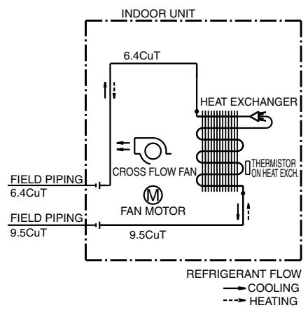
flowchart
graph TD
    A["INDOOR UNIT"] --> B["6.4CuT"]
    B --> C["CROSS FLOW FAN"]
    C --> D["FAN MOTOR"]
    D --> E["9.5CuT"]
    E --> F["9.5CuT"]
    G["HEAT EXCHANGER"] --> H["THERMISTOR ON HEAT EXCH."]
    I["FIELD PIPING 6.4CuT"] --> B
    J["FIELD PIPING 9.5CuT"] --> D
    K["REFRIGERANT FLOW"] --> L["COOLING"]
    K --> M["HEATING"]
FTXG50JV1BW(A)
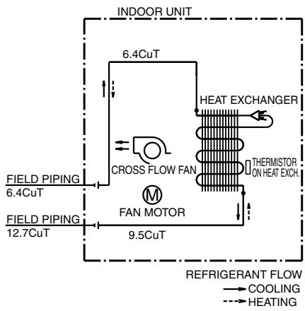
flowchart
graph TD
    A["INDOOR UNIT"] --> B["6.4CuT"]
    B --> C["CROSS FLOW FAN"]
    C --> D["FAN MOTOR"]
    D --> E["9.5CuT"]
    E --> F["HEAT EXCHANGER"]
    F --> G["THERMISTOR ON HEAT EXCH."]
    H["FIELD PIPING 6.4CuT"] --> I["FIELD PIPING 12.7CuT"] --> J["FIELD PIPING"]
    K["REFRIGERANT FLOW"] --> L["COOLING"]
    K --> M["HEATING"]
4D065855B
4D065856C
FTXS20/25K2V1B, CTXS15/35K2V1B
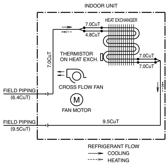
flowchart
graph TD
    A["INDOOR UNIT"] --> B["HEAT EXCHANGER"]
    B --> C["THERMISTOR ON HEAT EXCH."]
    C --> D["CROSS FLOW FAN"]
    D --> E["FAN MOTOR"]
    E --> F["9.5CuT"]
    F --> G["REFRIGERANT FLOW"]
    G --> H["COOLING"]
    G --> I["HEATING"]
    J["FIELD PIPING (6.4CuT)"] --> K["7.0CuT"]
    L["FIELD PIPING (9.5CuT)"] --> M["9.5CuT"]
    N["7.0CuT"] --> O["HEAT EXCHANGER"]
    P["7.0CuT"] --> Q["HEAT EXCHANGER"]
    R["7.0CuT"] --> S["HEAT EXCHANGER"]
4D058926N
FTXS25/35/42J2V1B
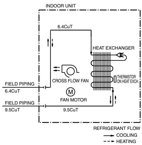
flowchart
graph TD
    A["INDOOR UNIT"] --> B["6.4CuT"]
    B --> C["CROSS FLOW FAN"]
    C --> D["FAN MOTOR"]
    D --> E["9.5CuT"]
    E --> F["9.5CuT"]
    F --> G["HEAT EXCHANGER"]
    G --> H["THERMISTOR ON HEAT EXCH."]
    I["FIELD PIPING 6.4CuT"] --> B
    J["FIELD PIPING 9.5CuT"] --> E
    K["REFRIGERANT FLOW"] --> L["COOLING"]
    K --> M["HEATING"]
4D058897H
FTXS50J2V1B
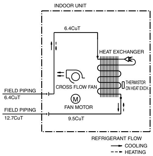
flowchart
graph TD
    A["INDOOR UNIT"] --> B["6.4CuT"]
    B --> C["CROSS FLOW FAN"]
    C --> D["FAN MOTOR"]
    D --> E["9.5CuT"]
    E --> F["HEAT EXCHANGER"]
    F --> G["THERMISTOR ON HEAT EXCH."]
    H["FIELD PIPING 6.4CuT"] --> I["FIELD PIPING 12.7CuT"]
    J["REFRIGERANT FLOW"] --> K["COOLING"]
    J --> L["HEATING"]
4D058898F
FTXS60GV1B
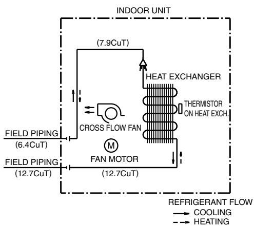
flowchart
graph TD
    A["INDOOR UNIT"] --> B["HEAT EXCHANGER"]
    B --> C["THERMISTOR ON HEAT EXCH."]
    D["FIELD PIPING (6.4CuT)"] --> E["CROSS FLOW FAN"]
    F["FIELD PIPING (12.7CuT)"] --> G["FAN MOTOR (12.7CuT)"]
    G --> H["REFRIGERANT FLOW"]
    I["COOLING"] --> J["→"]
    K["HEATING"] --> L["→"]
    M["FIELD PIPING (7.9CuT)"] --> N["→"]
    O["FIELD PIPING (12.7CuT)"] --> P["→"]
4D040081Y
FTXS71GV1B
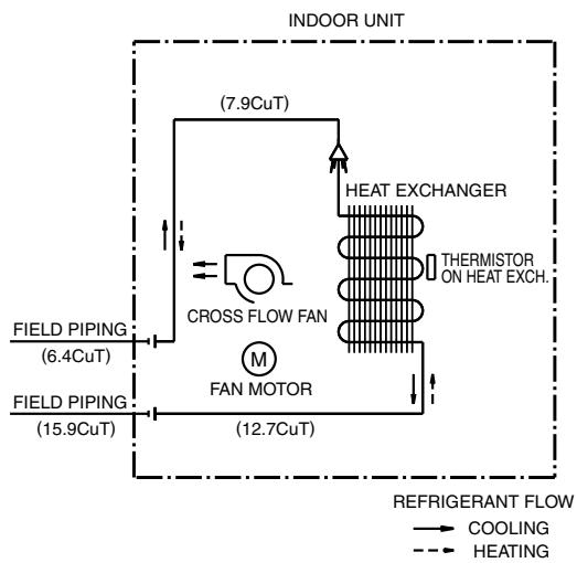
flowchart
graph TD
    A["INDOOR UNIT"] --> B["HEAT EXCHANGER"]
    B --> C["THERMISTOR ON HEAT EXCH."]
    D["FIELD PIPING (6.4CuT)"] --> E["CROSS FLOW FAN"]
    F["FIELD PIPING (15.9CuT)"] --> G["FAN MOTOR"]
    E --> H["HEAT EXCHANGER"]
    G --> I["HEAT EXCHANGER"]
    H --> J["COOLING"]
    I --> K["COOLING"]
    L["REFRIGERANT FLOW"] --> M["→ COOLING"]
    L --> N["→ HEATING"]
4D040082W
1.2.2 Floor Standing Type
FVXG25/35K2V1B
FVXG50K2V1B
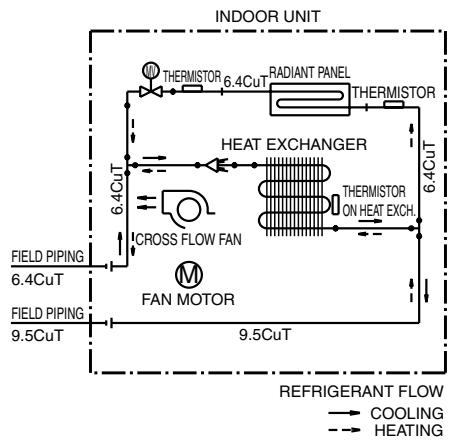
flowchart
graph TD
    A["INDOOR UNIT"] --> B["HEAT EXCHANGER"]
    B --> C["ICROSS FLOW FAN"]
    C --> D["FAN MOTOR"]
    D --> E["9.5CuT"]
    E --> F["FIELD PIPING 6.4CuT"]
    F --> G["FIELD PIPING 9.5CuT"]
    G --> H["REFRIGERANT FLOW"]
    H --> I["COOLING"]
    H --> J["HEATING"]
    B --> K["THERMISTOR 6.4CuT"]
    B --> L["RADIANT PANEL"]
    B --> M["THERMISTOR"]
    B --> N["ICROSS FLOW FAN"]
    B --> O["THERMISTOR ON HEAT EXCH."]
4D071597
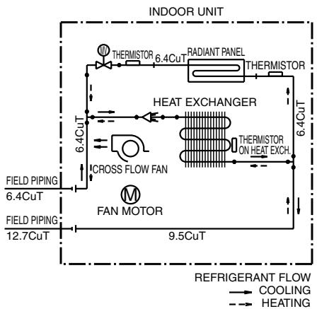
flowchart
graph TD
    A["INDOOR UNIT"] --> B["FIELD PIPING 6.4CuT"]
    A --> C["FIELD PIPING 12.7CuT"]
    B --> D["ICROSS FLOW FAN"]
    C --> E["FAN MOTOR"]
    D --> F["RADIANT PANEL"]
    E --> G["HEAT EXCHANGER"]
    F --> H["THERMISTOR 6.4CuT"]
    G --> I["THERMISTOR ON HEAT EXCH. 6.4CuT"]
    H --> J["9.5CuT"]
    I --> J
    J --> K["REFRIGERANT FLOW"]
    style A fill:#f9f,stroke:#333
    style B fill:#ccf,stroke:#333
    style C fill:#cfc,stroke:#333
    style D fill:#fcc,stroke:#333
    style E fill:#cff,stroke:#333
    style F fill:#ffc,stroke:#333
    style G fill:#cfc,stroke:#333
    style H fill:#fcc,stroke:#333
    style I fill:#ffc,stroke:#333
    style J fill:#fcc,stroke:#333
    style K fill:#ffc,stroke:#333
4D071598
FVXS25/35FV1B
FVXS50FV1B
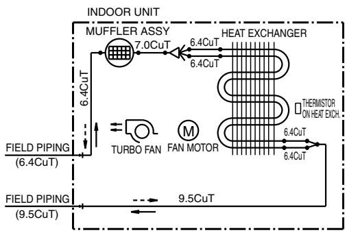
flowchart
graph TD
    A["INDOOR UNIT"] --> B["MUFFLER ASSY"]
    B --> C["HEAT EXCHANGER"]
    C --> D["TURBO FAN"]
    D --> E["FAN MOTOR"]
    E --> F["THERMISTOR ON HEAT EXCH."]
    F --> G["FIELD PIPING (6.4CuT)"]
    G --> H["FIELD PIPING (9.5CuT)"]
    B --> I["6.4CuT"]
    I --> J["7.0CuT"]
    J --> K["6.4CuT"]
    K --> L["6.4CuT"]
    L --> M["6.4CuT"]
    M --> N["9.5CuT"]
REFRIGERANT FLOW → COOLING --→ HEATING
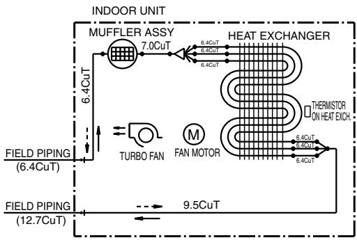
flowchart
graph TD
    A["INDOOR UNIT"] --> B["MUFFLER ASSY"]
    B --> C["HEAT EXCHANGER"]
    C --> D["TURBO FAN"]
    D --> E["FAN MOTOR"]
    E --> F["6.4CuT"]
    F --> G["6.4CuT"]
    G --> H["6.4CuT"]
    H --> I["6.4CuT"]
    I --> J["9.5CuT"]
    J --> K["FIELD PIPING (12.7CuT)"]
    L["FIELD PIPING (6.4CuT)"] --> M["TURBO FAN"]
    M --> N["FAN MOTOR"]
    N --> O["6.4CuT"]
    O --> P["6.4CuT"]
    P --> Q["6.4CuT"]
    Q --> R["6.4CuT"]
    R --> S["6.4CuT"]
    S --> T["6.4CuT"]
    T --> U["6.4CuT"]
    U --> V["6.4CuT"]
    V --> W["6.4CuT"]
    W --> X["6.4CuT"]
    X --> Y["6.4CuT"]
REFRIGERANT FLOW → COOLING --→ HEATING
4D056137B
4D056138C
1.2.3 Floor / Ceiling Suspended Dual Type
FLXS25/35BAVMB
FLXS50/60BAVMB
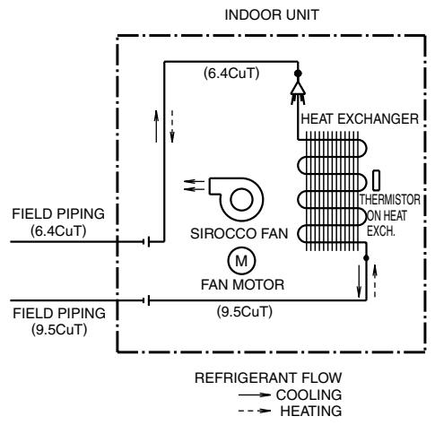
flowchart
graph TD
    A["INDOOR UNIT"] --> B["FIELD PIPING (6.4CuT)"]
    B --> C["SIROCCO FAN"]
    C --> D["FAN MOTOR"]
    D --> E["HEAT EXCHANGER"]
    E --> F["THERMISTOR ON HEAT EXCH."]
    F --> G["REFRIGERANT FLOW"]
    G --> H["COOLING"]
    G --> I["HEATING"]
4D048722B
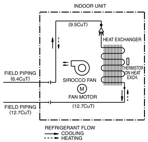
text_image
INDOOR UNIT (9.5CuT) HEAT EXCHANGER SIROCCO FAN M FAN MOTOR THERMISTOR ON HEAT EXCH. FIELD PIPING (6.4CuT) FIELD PIPING (12.7CuT) (12.7CuT) REFRIGERANT FLOW COOLING HEATING4D048724B
1.2.4 Duct Connected Type
FDXS25/35E7VMB, FDXS50/60C7VMB
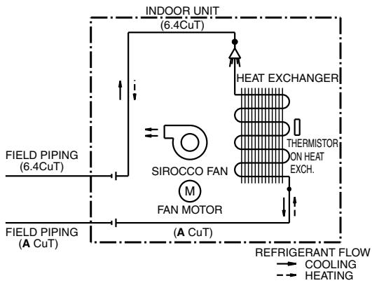
flowchart
graph TD
    A["INDOOR UNIT (6.4CuT)"] --> B["FAN MOTOR"]
    B --> C["SIROCCO FAN M"]
    C --> D["HEAT EXCHANGER"]
    D --> E["THERMISTOR ON HEAT EXCH."]
    E --> F["COOLING"]
    E --> G["HEATING"]
    H["FIELD PIPING (6.4CuT)"] --> I["INDOOR UNIT (6.4CuT)"]
    J["FIELD PIPING (A CuT)"] --> K["INDOOR UNIT (6.4CuT)"]
    L["REFRIGERANT FLOW"] --> M["COOLING"]
    L --> N["HEATING"]
| A | A | ||
| FDXS25E7VMB | 9.5 | FDXS50C7VMB | 12.7 |
| FDXS35E7VMB | FDXS60C7VMB |
C: 4D045449Q
1.2.5 Ceiling Mounted Cassette Type
FCQG35/50/60FVEB
REFRIGERANT FLOW
COOLING
HEATING - →
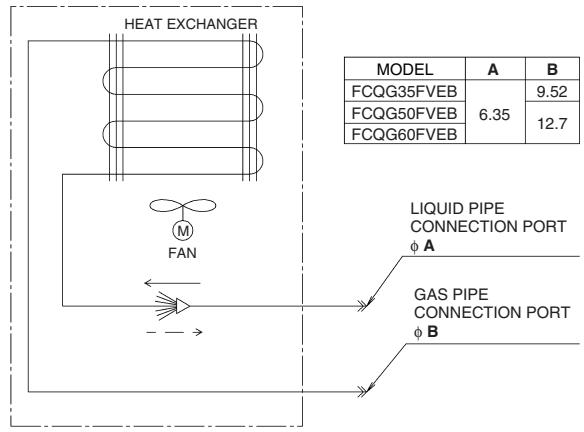
flowchart
graph TD
    A["HEAT EXCHANGER"] --> B["FAN"]
    B --> C["LIQUID PIPE CONNECTION PORT φ A"]
    B --> D["GAS PIPE CONNECTION PORT φ B"]
    E["MODEL"] --> F["A 9.52"]
    E --> G["B 12.7"]
    H["FCQG35FVEB"] --> I["6.35"]
    J["FCQG50FVEB"] --> K["12.7"]
C: 4D076993
FFQ25/35/50/60B9V1B
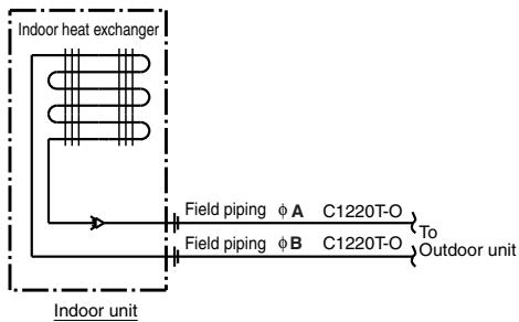
flowchart
graph TD
    A["Indoor heat exchanger"] --> B["Field piping φA C1220T-O"]
    A --> C["Field piping φB C1220T-O"]
    B --> D["To Outdoor unit"]
    C --> D
    style A fill:#f9f,stroke:#333
    style D fill:#ccf,stroke:#333
| MODEL | A | B |
| FFQ25/35B9V1B | 6.4 | 9.5 |
| FFQ50/60B9V1B | 6.4 | 12.7 |
C: 4D039335B
1.2.6 Ceiling Suspended Type
FHQ35/50/60BWV1B
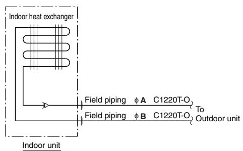
text_image
Indoor heat exchanger Field piping φ A C1220T-O Field piping φ B C1220T-O To Outdoor unit Indoor unit| MODEL | A | B |
| FHQ35BWV1B | 6.4 | 9.5 |
| FHQ50, 60BWV1B | 6.4 | 12.7 |
C: 4D037995L
1.2.7 Ceiling Mounted Built-in Type
FDBQ25B8V1
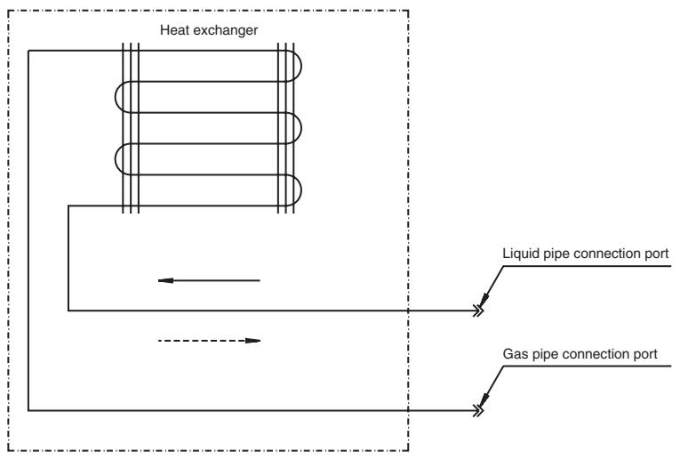
flowchart
graph TD
    A["Heat exchanger"] --> B["Liquid pipe connection port"]
    A --> C["Gas pipe connection port"]
    B --> D["Return to heat exchanger"]
    C --> E["Return to heat exchanger"]
Refrigerant flow
Refrigerant pipe connection port diameters
| Model | Gas | Liquid |
| FDBQ25B8V1 | 9.52 | 6.35 |
C: 3TW20815-1B
FBQ35/50/60C8VEB
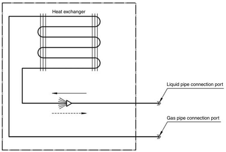
flowchart
graph TD
    A["Heat exchanger"] --> B["Liquid pipe connection port"]
    A --> C["Gas pipe connection port"]
    B --> D["Return to heat exchanger"]
    C --> D
    style A fill:#f9f,stroke:#333
    style B fill:#ccf,stroke:#333
    style C fill:#cfc,stroke:#333
Refrigerant flow
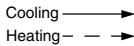
Refrigerant pipe connection port diameters
| Model | Gas | Liquid |
| FBQ35C | 9.52 | 6.35 |
| FBQ50C | 12.70 | 6.35 |
| FBQ60C | 12.70 | 6.35 |
C: 3TW31275-1
2. Wiring Diagrams
2.1 Outdoor Unit
2.1.1 Cooling Only
3MKS50E3V1B
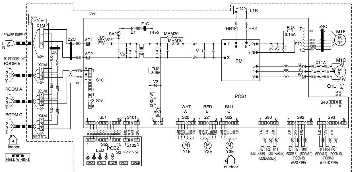
text_image
POWER SUPPLY TO INDOOR UNIT ROOM B ROOM A ROOM C indoor FIELD WIRING GRN YLW X1M L N Z3C BLK WHT Z2C BRN AC1 FU1 30A V2- SA2 E1 GRN Z1C E2 MRM20 MRM10 V6 V11 H1R HR1 6(P) 7(N) PM1 FUX3 3.15A RED Z4C M1F M T S70 1 BLU BRN ORG WHT U RED X11A V YLW BLU BLU M1C M Q1L S40 1 4 PCB1 WHT A S20 RED B BLU C S22 6 S90 6 S92 8 S93 9 BLK R3T R2T R1T (OUTDOOR) (CONDENSER) R8T R9T R10T (ROOM-A) (ROOM-C)| Z1C-Z4C | : FERRITE CORE | MRM10, MRM20 | L | : LIVE | M1C | : COMPRESSOR MOTOR |
| X1M-X4M | : TERMINAL STRIP | MRC/W | : MAGNETIC RELAY | N | : NEUTRAL | M1F |
| Y1E-Y3E | : ELECTRONIC EXPANSION VALVE COIL | R1T-R6T | SW1 | : FORCED OPERATION ON/OFF SW (SW1) | L1R | : REACTOR |
| V2, V3, V5, V6, V11 | : VARISTOR | R8T-R10T | SW2 | : SELECT SW (SW2) | Q1L | : OVERLOAD PROTECTOR |
| SA2 | : SURGE ARRESTER | S2-S102 | SW3 | : WIRING ERROR CHECK SW (SW3) | PM1 | : POWER MODULE |
| FU1, FU2, FU3 | : FUSE | LED1-LED4 | SW4 | : PRIORITY ROOM SETTING SW (SW4) | PCB1, 2 | : PRINTED CIRCUIT BOARD |
| AC1, AC2 | LEDA | SW5 | : NIGHT QUIET MODE SETTING SW (SW5) | SHEET METAL | : TERMINAL STRIP FIXED PLATE | |
| U, V, W, X11A | ||||||
| E1, E2 | ||||||
| HR1, HR2 | : CONNECTOR |
4MKS58E3V1B
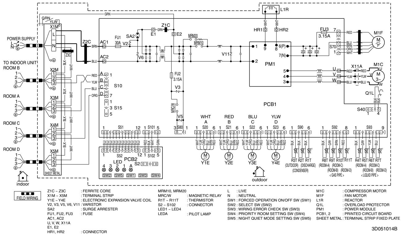
text_image
POWER SUPPLY TO INDOOR UNIT ROOM B ROOM A ROOM C ROOM D indoor Z1C ~ Z3C : FERRITE CORE X1M ~ X5M : TERMINAL STRIP Y1E ~ Y4E : ELECTRONIC EXPANSION VALVE COIL V2, V3, V5, V6, V11 : VARISTOR SA2 : SURGE ARRESTER FU1, FU2, FU3 : FUSE AC1, AC2 U, V, W, X11A E1, E2 HR1, HR2 : CONNECTOR GRN L1R L1M BRN BLU S2C S10 S15 S5M S40 S40 S70 S70 POM1 PCB1 WHT A 1 S20 6 1 S21 6 1 S22 6 1 S23 6 1 S90 6 1 S92 8 1 S93 9 MRC/W : MAGNETIC RELAY N : NEUTRAL M1F : FAN MOTOR R1T ~ R11T : THERMISTOR SW1: FORCED OPERATION ON/OFF SW (SW1) S2 ~ S102 : CONNECTOR SW2: SELECT SW (SW2) LED1 ~ LED4 : PILOT LAMP SW3: WIRING ERROR CHECK SW (SW3) LEDA : PILOT LAMP SW4: PRIORITY ROOM SETTING SW (SW4) SW5: NIGHT QUIET MODE SETTING SW (SW5) L : LIVE M1C : COMPRESSOR MOTOR HR1 9 6(P) 7(N) MRM20 MRM10 E1 E2 Z1C E2 FU1 30A V2 V6 V112 HR2 7 V3 3.15A 5 4 3 FU2 3.15A V5 V3 MRC/W MDW PCB2 PCB2 S2 S80 S80 S80 S80 S80 S80 S80 S80 S80 S80 S80 S80 S80 S80 S80 S80 S80 S80 S80 S80 S80 S80 S80 S80 S80 S80 S80 S80 S80 S80 S80 S80 S80 S80 FIELD WIRING M1F M1C RED RED M1C M3- M3- Q1L QOLI BLU BLU BLU BLU BLU BLU BLU BLU BLU BLU BLU BLU BLU BLU BLU BLU BLU BLU BLU BLU BLU BLU BLU BLU BLU BLU BLU BLU BLU BLU BLU BLU BLU BLU BLU BLU BLU BLU BLU BLU BLU BLU BLU BLU BLU BLU BLU BLU BLU BLU BLU SLT R3T R2T R1T (OUTDOOR) (DISCHARGE) (CONDENSER) Y1E Y2E Y3E Y4E outdoor M Y1E Y2E Y3E Y4E R3T R2T R1T (OUTDOOR) (DISCHARGE) (CONDENSER) BLU C BRL DRD RD RRL DRD RD RRL DRD RD RRL DRD RD RRL DRD RD RRL DRD RD RRL DRD RD RRL DRD RD RRL DRD RD RRL DRD RD RRL DRD RD RRL DRD RD RRL DRD RD RRL DRD RD RRL DRD RD RRL DRD RD RRL DRD RD RRL DRD RD RRL DRD RD RRL DRD RD RRL DRD RD GASE PIPE> R8T R9T R10T R11T (ROOM-A) (ROOM-C) (ROOM-B) (ROOM-D) (ROOM-A) (ROOM-C) (ROOM-B) (ROOM-D) (ROOM-B) (ROOM-D) (LIQUID PIPE) SHEET MEDL S40 1 4 S70 1 S70 1 S40 1 44MKS75F2V1B
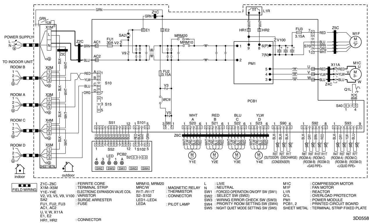
text_image
POWER SUPPLY TO INDOOR UNIT ROOM B ROOM A ROOM C ROOM D indoor GRN Y1M L N Z3C X2M 1 2 3 4 5 6 7 8 9 10 11 12 13 14 15 16 17 18 19 20 21 22 23 24 25 26 27 28 29 30 31 32 33 34 35 36 37 38 39 40 41 42 43 44 45 46 47 48 49 50 51 52 53 54 55 56 57 58 59 60 61 62 63 64 65 66 67 68 69 70 71 72 73 74 75 76 77 78 79 80 81 82 83 84 85 86 87 88 89 90 91 92 93 94 95 96 97 98 99 100 L1R GRN SA2 E1 E2 MRM20 MRM10 FU1 30A V2 Z V9 Z FU2 3.15A V3 MRCW V5 S10 S15 S51 S101 S S80 S WHT A RED B BLU C YLW D S23 S S90 S S92 S S93 S FERRITE CORE MRM10, MRM20 L : LIVE M1C : COMPRESSOR MOTOR X1M-X5M : TERMINAL STRIP MRC/W MUNIC : FAN MOTOR Y1E-Y4E ELECTRONIC EXPANSION VALVE COIL R1T-R11T THERMISTOR SW1 FORCED OPERATION ON/OFF SW (SW1) L1R REACTOR V2, V3, V5, V9, V100 VARISTOR SA2 S2-S102 CONNECTOR SW2 SELECT SW (SW2) Q1L OVERLOAD PROTECTOR FU1, FU2, FU3 LED LED-LED-LED LALE PILOT LAMP SW3 WIRING ERROR CHECK SW (SW3) PM1 POWER MODULE AC1, AC2 U, V, W, X11A LED-LED-LED LEDA PRIORITY ROOM SETTING SW (SW4) PCB1, 2 PRINTED CIRCUIT BOARD E1, E2 HR1, HR2 : CONNECTOR SW5 NIGHT QUIET MODE SETTING SW (SW5) SHEET METAL: TERMINAL STRIP FIXED PLATE 3D05585MKS90E2V3B
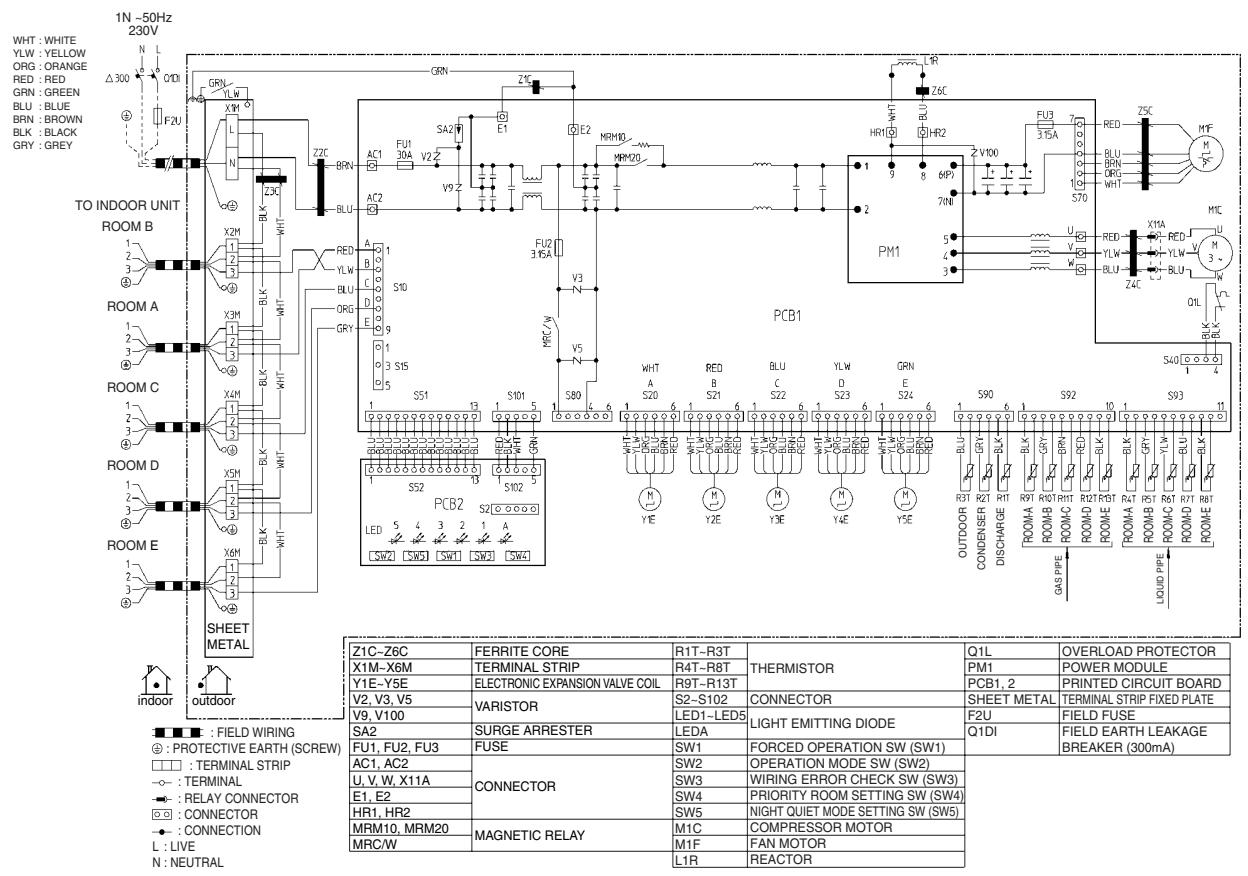
text_image
1N ~50Hz 230V WHT : WHITE YLW : YELLOW ORG : ORANGE RED : RED GRN : GREEN BLU : BLUE BRN : BROWN BLK : BLACK GRY : GREY TO INDOOR UNIT ROOM B ROOM A ROOM C ROOM D ROOM E SHEET METAL INDOOR OUTDOOR ■ : FIELD WIRING ○ : PROTECTIVE EARTH (SCREW) □ : TERMINAL STRIP ○ : TERMINAL ● : RELAY CONNECTOR ○ : CONNECTOR ● : CONNECTION L : LIVE N : NEUTRAL GRN X1M-X6M X1E-Y5E V2, V3, V5 V9, V100 SA2 FU1, FU2, FU3 AC1, AC2 U, V, W, X11A E1, E2 HR1, HR2 MRM10, MRM20 MRC/W ZC ZC' SA2/30A V2 V9 ZC BRN BLU BLU BRN BLU BLU BLU BLU BLU BLU BLU BLU BLU BLU BLU BLU BLU BLU BLU BLU BLU BLU BLU BLU BLU BLU BLU BLU BLU BLU BLU BLU BLU BLU BLU BLU BLU BLU2TW27596-1A
2.1.2 Heat Pump
3MXS40K2V1B, 3MXS52E3V1B
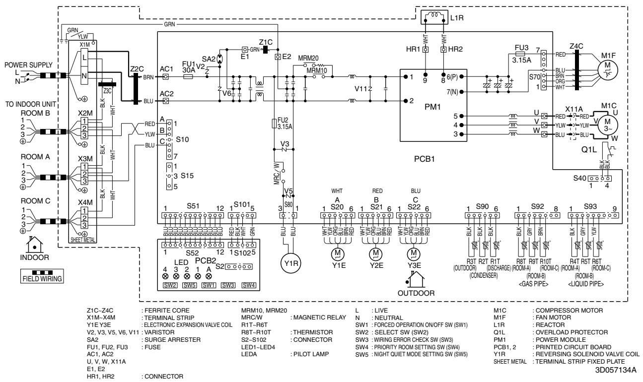
text_image
POWER SUPPLY N TO INDOOR UNIT ROOM B 1 2 3 4 ROOM A 1 2 3 4 ROOM C 1 2 3 5 INDOOR FIELD WIRING GRN YLW X1M L N Z3C BRN BLU X2C 1 2 3 4 X3M 1 2 3 4 X4M 1 2 3 SHEET METAL GRN Z2C SA2 E1 FU1 V2 V6 A 1 B 3 C 7 S10 S15 5 S51 12 1 S101 5 LED PCB2 1 S1025 4 3 2 1 A S20 6 SW2 SW5 SW1 SW3 SW4 GRN Z1C E2 MRM20 MRM10 V112 PM1 7(N) E1 FU2 3.15A V3 V5 S80 Y1R WHT A RED BLU C S22 6 OUTDOOR 1 S90 6 1 S92 8 1 S93 9 AC1 SA2 MRM20 R1T-R6T THERMISTOR SW2 SELECT SW (SW2) Q1L FAN MOTOR L1R REACTOR AC1 AC2 R8T-R10T CONNECTOR SW3 WIRING ERROR CHECK SW (SW3) PM1 POWER MODULE AC1 AC2 LED-LED4 LEDA PILOT LAMP SW4 PRIORITY ROOM SETTING SW (SW4) PCB1,2 PRINTED CIRCUIT BOARD Y1R REVERSING SOLENOID VALVE COIL SHEET METAL TERMINAL STRIP FIXED PLATE 3D057134A3MXS68G2V1B
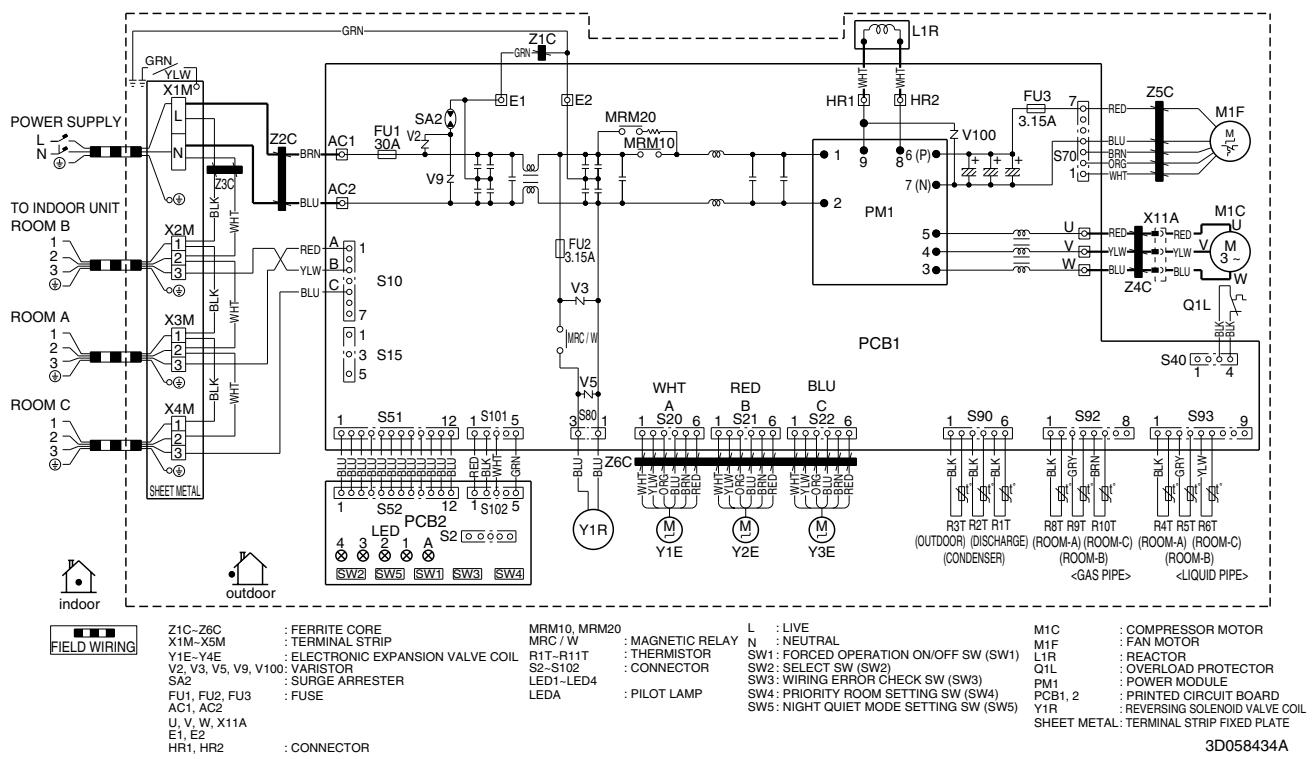
text_image
POWER SUPPLY TO INDOOR UNIT ROOM B ROOM A ROOM C INDOOR FIELD WIRING GRN Y1M X1M L N Z2C BRN AC1 FU1 30A SA2 V2 E1 E2 MRM20 MRM10 HR1 HR2 F5 3.15A RED S70 1 Z5C M1F M1C M3~ Q1L S40 1 4 PCB1 S40 1 4 S80 S90 6 R3T R2T R1T (OUTDOOR) (DISCHARGE) (CONDENSER) R8T R9T R10T (ROOM-A) (ROOM-C) (ROOM-B) < GAS PIPE> S40 1 4 PCB2 LED S20 S21 S22 S23 S24 S25 S26 S27 S28 S29 S30 S31 S32 S33 S34 S35 S36 S37 S38 S39 S40 S41 S42 S43 S44 S45 S46 S47 S48 S49 S50 S51 S52 SW2 SW5 SW1 SW3 SW4 Z1C-Z6C : FERRITE CORE MRM10, MRM20 L : LIVE M1C : COMPRESSOR MOTOR X1M-X5M : TERMINAL STRIP MRC / W : MAGNETIC RELAY N : NEUTRAL M1F : FAN MOTOR Y1E-Y4E : ELECTRONIC EXPANSION VALVE COIL R1T-R11T : THERMISTOR SW1: FORCED OPERATION ON/OFF SW (SW1) L1R : REACTOR V2, V3, V5, V9, V100: VARISTOR S2-S102 : CONNECTOR SW2: SELECT SW (SW2) Q1L : OVERLOAD PROTECTOR SA2 : SURGE ARRESTER LED1-LED4 : SWITCH SW3: WIRING ERROR CHECK SW (SW3) PM1 : POWER MODULE FU1, FU2, FU3 : FUSE LEDA : PRILOT LAMP SW4: PRIORITY ROOM SETTING SW (SW4) PCB1, 2 : PRINTED CIRCUIT BOARD AC1, AC2 U, V, W, X11A E1, E2 HR1, HR2 : CONNECTOR SW5: NIGHT QUIET MODE SETTING SW (SW5) Y1R : REVERSING SOLENOID VALVE COIL SHEET METAL: TERMINAL STRIP FIXED PLATE 3D058434A4MXS68F2V1B
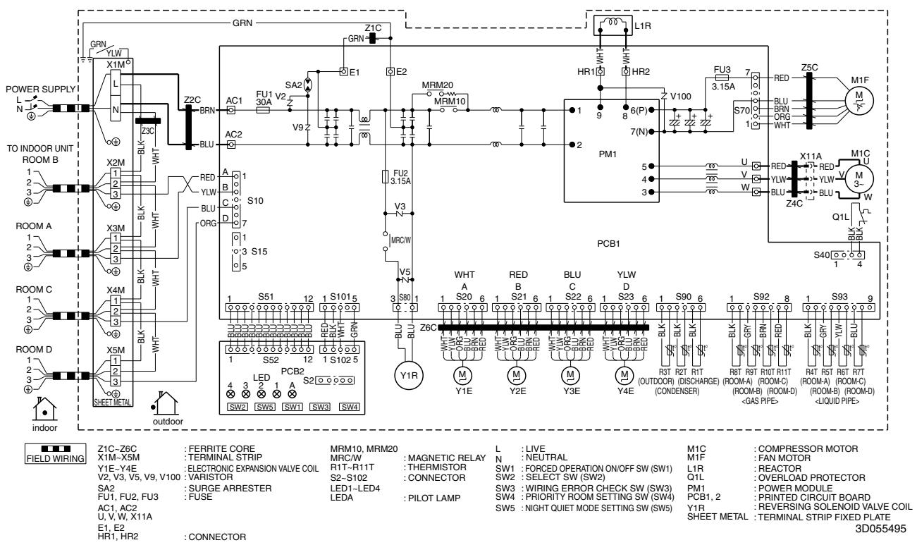
text_image
POWER SUPPLY TO INDOOR UNIT ROOM B ROOM A ROOM C ROOM D indoor GRN Y1M L N X2C BRN BLK Z3C X2M 1 2 3 4 5 6 7 8 9 10 11 12 13 14 15 16 17 18 19 20 21 22 23 24 25 26 27 28 29 30 31 32 33 34 35 36 37 38 39 40 41 42 43 44 45 46 47 48 49 50 51 52 53 54 55 56 57 58 59 60 61 62 63 64 65 66 67 68 69 70 71 72 73 74 75 76 77 78 79 80 81 82 83 84 85 86 87 88 89 90 91 92 93 94 95 96 97 98 99 100 101 102 103 104 105 106 107 108 109 110 111 112 113 114 115 116 117 118 119 120 121 122 123 124 125 126 127 128 129 130 131 132 133 134 135 136 137 138 139 140 141 142 143 144 145 146 147 148 149 150 151 152 153 154 155 156 157 158 159 160 161 162 163 164 165 166 167 168 169 170 171 172 173 174 175 176 177 178 179 180 181 182 183 184 185 186 187 188 189 190 191 192 193 194 195 196 197 198 199 2004MXS80E2V3B
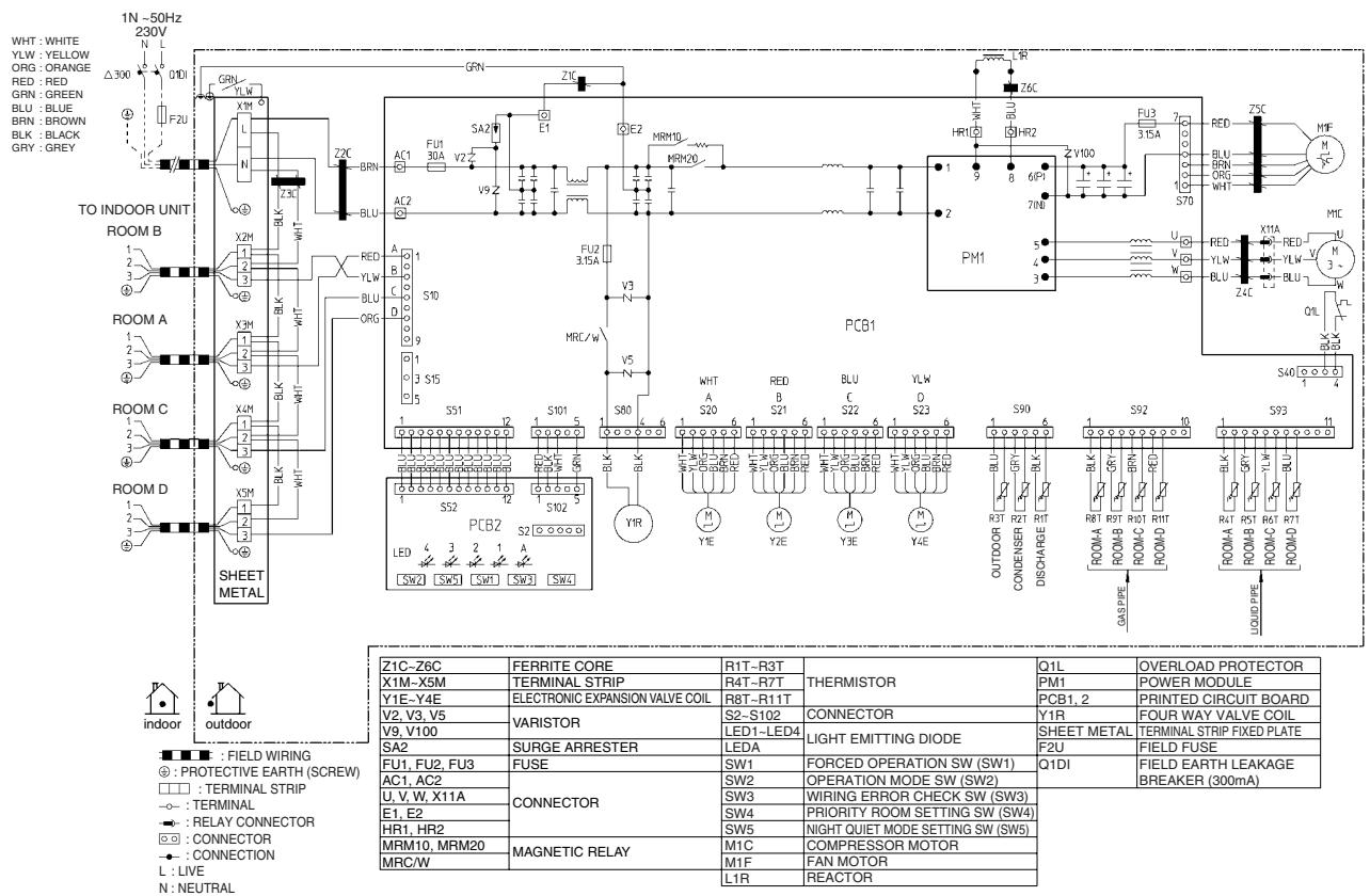
text_image
1N -50Hz 230V WHT : WHITE YLW : YELLOW ORG : ORANGE RED : RED GRN : GREEN BLU : BLUE BRN : BROWN BLK : BLACK GRY : GREY TO INDOOR UNIT ROOM B ROOM A ROOM C ROOM D SHEET METAL INDOOR outdoor Z1C-Z6C X1M-X5M Y1E-Y4E V2, V3, V5 V9, V100 SA2 FU1, FU2, FU3 AC1, AC2 U, V, W, X11A E1, E2 HR1, HR2 MRM10, MRM20 MRC/W FERRITE CORE TERMINAL STRIP ELECTRONIC EXPANSION VALVE COIL VARISTOR SURGE ARRESTER FUSE CONNECTOR MAGNETIC RELAY R1T-R3T R4T-R7T R8T-R11T LED1-LED4 LEDA SW1 SW2 SW3 SW4 SW5 M1C M1F L1R FORCED OPERATION SW (SW1) OPERATION MODE SW (SW2) WIRING ERROR CHECK SW (SW3) PRIORITY ROOM SETTING SW (SW4) NIGHT QUIET MODE SETTING SW (SW5) COMPRESSOR MOTOR FAN MOTOR REACTOR THERMISTOR CONNECTOR LIGHT EMITTING DIODE FORCED OPERATION SW (SW1) POWER MODULE PCB1, 2 Y1R SHEET METAL FIELD FUSE OVERLOAD PROTECTOR POWER MODULE PRINTED CIRCUIT BOARD FOUR WAY VALVE COIL TERMINAL STRIP FIXED PLATE FIELD EARTH LEAKAGE BREAKER (300mA)2TW27576-1B
5MXS90E2V3B
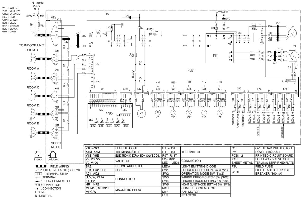
text_image
1N ~50Hz 230V WHT : WHITE YLW : YELLOW ORG : ORANGE RED : RED GRN : GREEN BLU : BLUE BRN : BROWN BLK : BLACK GRY : GREY Δ300 F2U TO INDOOR UNIT ROOM B 1 2 3 4 5 6 7 8 9 10 11 12 13 14 15 16 17 18 19 20 21 22 23 24 25 26 27 28 29 30 31 32 33 34 35 36 37 38 39 40 41 42 43 44 45 46 47 48 49 50 51 52 53 54 55 56 57 58 59 60 61 62 63 64 65 66 67 68 69 70 71 72 73 74 75 76 77 78 79 80 81 82 83 84 85 86 87 88 89 90 91 92 93 94 95 96 97 98 99 100 101 102 103 104 105 106 107 108 109 110 111 112 113 114 115 116 117 118 119 120 121 122 123 124 125 126 127 128 129 130 131 132 133 134 135 136 137 138 139 140 141 142 143 144 145 146 147 148 149 150 151 152 153 154 155 156 157 158 159 160 161 162 163 164 165 166 167 168 169 170 171 172 173 174 175 176 177 178 179 180 181 182 183 184 185 186 187 188 189 190 191 192 193 194 195 196 197 198 199 2002TW27586-1A
2.2 Indoor Unit
2.2.1 Wall Mounted Type
FTXG25/35/50JV1BW(A)
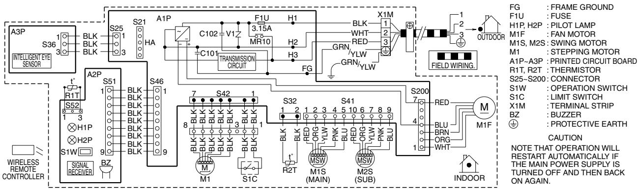
text_image
A3P INTELLIGENT EYE SENSOR S36 1 3 BLK BLK BLK S25 1 3 HA S21 C102 V1 F1U 3.15A MR10 H1 H2 H3 TRANSMISSION CIRCUIT X1M 1 2 3 GRN YLW GRN YLW FG FIELD WIRING. F1U: FUSE H1P, H2P: PILOT LAMP M1F: FAN MOTOR M1S, M2S: SWING MOTOR M1: STEPPING MOTOR A1P~A3P: PRINTED CIRCUIT BOARD R1T, R2T: THERMISTOR S25~S200: CONNECTOR S1W: OPERATION SWITCH S1C: LIMIT SWITCH X1M: TERMINAL STRIP BZ: BUZZER ⊕: PROTECTIVE EARTH CAUTION NOTE THAT OPERATION WILL RESTART AUTOMATICALLY IF THE MAIN POWER SUPPLY IS TURNED OFF AND THEN BACK ON AGAIN. A2P S51 1 3 BLK BLK BLK S46 1 7 S42 1 8 BLK BLK BLK BLK BLK BLK BLK BLK BLK BLK BLK BLK BLK BLK BLK BLK BLK BLK BLK BLK BLK BLK BLK BLK BLK BLK BLK BLK BLK BLK BLK BLK BLK BLK BLK BLK BLK BLK BLK BLK BLK BLK BLK BLK BLK BLK BLK BLK BLK BLK BLk S52 1 3 H1P H2P S1W 9 S1C M1 M2S (MAIN) M2S (SUB) INDOOR3D065507D
FTXS20/25K2V1B, CTXS15/35K2V1B
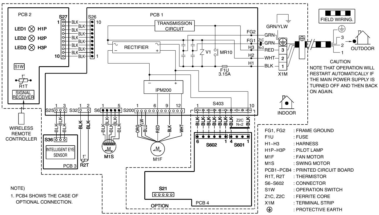
flowchart
graph TD
    subgraph_PCB_2["PCB 2"]
        A1["LED1 H1P"] --> B1["BLK BLK"]
        A2["LED2 H2P"] --> B2["BLK BLK"]
        A3["LED3 H3P"] --> B3["BLK BLK"]
        B1 --> C1["S27"]
        B2 --> C2["S26"]
        B3 --> C3["S10"]
        C1 --> D1["TRANSMISSION CIRCUIT"]
        C2 --> D2["RECTIFIER"]
        C3 --> D3["IPM200"]
        D1 --> E1["VG2"]
        D2 --> E2["FG1 ZIC"]
        D3 --> E3["RED H3"]
        E1 --> F1["F1U 3.15A"]
        E2 --> F2["WHT H2"]
        E3 --> F3["BLK H1"]
        F1 --> G1["X1M"]
        F2 --> G2["X1M"]
        F3 --> G3["X1M"]
    end

    subgraph_PCB_1["PCB 1"]
        D1 --> E1
        D2 --> E2
        D3 --> E3
        E1 --> F1
        E2 --> F2
        E3 --> F3
        F1 --> G1
        F2 --> G2
        F3 --> G3
    end

    subgraph_PCB_4["PCB 4"]
        D1 --> E1
        D2 --> E2
        D3 --> E3
        E1 --> F1
        E2 --> F2
        E3 --> F3
        F1 --> G1
        F2 --> G2
        F3 --> G3
    end

    subgraph_PCB_5["PCB 5"]
        D1 --> E1
        D2 --> E2
        D3 --> E3
        E1 --> F1
        E2 --> F2
        E3 --> F3
    end

    subgraph_PCB_6["PCB 6"]
        D1 --> E1
        D2 --> E2
        D3 --> E3
        E1 --> F1
        E2 --> F2
        E3 --> F3
    end

    subgraph_PCB_7["PCB 7"]
        D1 --> E1
        D2 --> E2
        D3 --> E3
        E1 --> F1
        E2 --> F2
        E3 --> F3
    end

    subgraph_PCB_8["PCB 8"]
        D1 --> E1
        D2 --> E2
        D3 --> E3
        E1 --> F1
        E2 --> F2
        E3 --> F3
    end

    subgraph_PCB_9["PCB 9"]
        D1 --> E1
        D2 --> E2
        D3 --> E3
        E1 --> F1
        E2 --> F2
        E3 --> F3
    end

    subgraph_PCB_10["PCB 10"]
        D1 --> E1
        D2 --> E2
        D3 --> E3
    end

    subgraph_PCB_11["PCB 11"]
        D1 --> E1
        D2 --> E2
        D3 --> E3
    end

    subgraph_PCB_12["PCB 12"]
        D1 --> E1
        D2 --> E2
        D3 --> E3
    end

    subgraph_PCB_13["PCB 13"]
        D1 --> E1
        D2 --> E2
        D3 --> E3
    end

    subgraph_PCB_14["PCB 14"]
        D1 --> E1
        D2 --> E2
        D3 --> E3
    end

    subgraph_PCB_15["PCB 15"]
        D1 --> E1
        D2 --> E2
        D3 --> E3
    end

    subgraph_PCB_16["PCB 16"]
        D1 --> E1
        D2 --> E2
        D3 --> E3
    end

    subgraph_PCB_17["PCB 17"]
        D1 --> E1
        D2 --> E2
        D3 --> E3
    end

    subgraph_PCB_18["PCB 18"]
        D1 --> E1
        D2 --> E2
        D3 --> E3
    end

    subgraph_PCB_19["PCB 19"]
        D1 --> E1
        D2 --> E2
        D3 --> E3
    end

    subgraph_PCB_20["PCB 20"]
        D1 --> E1
        D2 --> E2
        D3 --> E3
    end

    subgraph_PCB_21["PCB 21"]
        D1 --> E1
        D2 --> E2
        D3 --> E3
    end

    subgraph_PCB_22["PCB 22"]
        D1 --> E1
        D2 --> E2
        D3 --> E3
    end

    subgraph_PCB_23["PCB 23"]
        D1 --> E1
        D2 --> E2
        D3 --> E3
    end

    subgraph_PCB_24["PCB 24"]
        D1 --> E1
        D2 --> E2
        D3 --> E3
    end

    subgraph_PCB_25["PCB 25"]
        S66["S66 INTELLIGENT EYE SENSOR"] --> S66R[BLK BLK BLK BLK BLK BLK BLK BLK BLK BLK BLK BLK BLK BLK BLK BLK BLK BLK BLK BLK BLK BLK BLK BLK BLK BLK BLK BLK BLK BLK BLK BLK BLK BLK BLK BLK BLK BLK BLK BLK BLK BLK BLK BLK BLK BLK BLK BLK BLK BLK BLK BLk BLk BLk BLk BLk BLk BLk BLk BLk BLk BLk BLk BLk BLk BLk BLk BLk BLk BLk BLk BLk BLk BLk BLk BLk BLk BLk BLk BLk BLk BLk BLk BLk BLk BLk BLk BLk BLk BLk BLk BLk BLk BLk BLk BLk BLk BLk BLk BLk BLk BLl

    note right of PCB_5: PCB_6: PCB_7 (NOTE)
    note right of PCB_8: PCB_9: PCB_7 (NOTE)
    note right of PCB_9: PCB_8: PCB_7 (NOTE)

    note right of PCB_9: PCB_7: PCB_8: PCB_9: PCB_7: PCB_8: PCB_7: PCB_8: PCB_9: PCB_7: PCB_8: PCB_9: PCB_7: PCB_8: PCB_9: PCB_7: PCB_8: PCB_9: PCB_7: PCB_8: PCB_9: PCB_7: PCB_8: PCB_9: PCB_7: PCB_8: PCB_9: PCB_7: PCB_9: PCB_8: PCB_9: PCB_7: PCB_8: PCB_9: PCB_7: PCB_8: PCB_9: PCB_7: PCB_8: PCB_9: PCB_7: PCB_8: PCB_9: PCB_7: PCB_8: PCB_9: PCB_7: PCB_8: PCB_8: PCB_9: PCB_7: PCB_8: PCB_9: PCB_7: PCB_8: PCB_9: PCB_7: PCB_8: PCB_9: PCB_7: PCB_8: PCB_9: PCB_7: PCB_8: PCB_9: PCB_7: PCB_8: PCB_7: PCB_8: PCB_9: PCB_7: PCB_8: PCB_9: PCB_7: PCB_8: PCB_9: PCB_7: PCB_8: PCB_9: PCB_7: PCB_8: PCBC
3D073474C
FTXS25/35/42/50J2V1B
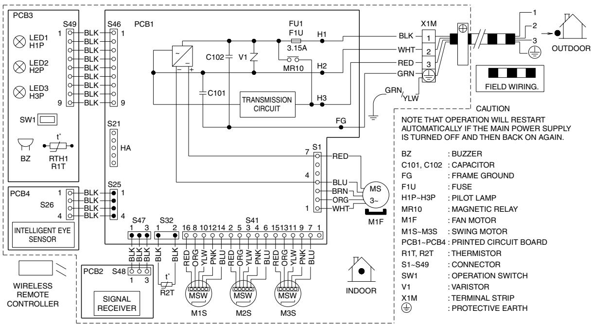
text_image
PCB3 LED1 H1P LED2 H2P LED3 H3P SW1 BZ RTH1 R1T PCB4 S26 INTELLIGENT EYE SENSOR WIRELESS REMOTE CONTROLLER S49 S46 PCB1 FU1 F1U H1 C102 V1 3.15A MR10 H2 C101 TRANSMISSION CIRCUIT H3 FG S21 HA S25 S47 S32 S41 S48 S47 1 2 3 4 5 6 7 8 9 10 11 12 13 14 15 16 17 18 19 20 21 22 23 24 25 26 27 28 29 30 31 32 33 34 35 36 37 38 39 40 41 42 43 44 45 46 47 48 49 50 51 52 53 54 55 56 57 58 59 60 61 62 63 64 65 66 67 68 69 70 71 72 73 74 75 76 77 78 79 80 S26 S25 S47 S32 S41 S48 S47 S32 S41 S48 S47 S32 S41 S48 S47 S32 S41 S48 S47 S32 S41 S48 S47 S32 S41 S48 S47 S32 S41 S48 S46 S32 S41 S48 S47 S32 S41 S48 S47 S32 S41 S48 S47 S32 S41 S48 S47 S32 S41 S48 S47 S32 S41 S48 S47 S33D058246F
FTXS60/71GV1B
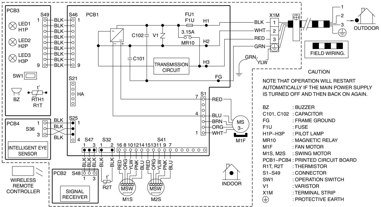
text_image
PCB3 LED1 H1P LED2 H2P LED3 H3P SW1 BZ RTH1 R1T PCB4 S36 INTELLIGENT EYE SENSOR WIRELESS REMOTE CONTROLLER S49 1 BLK BLK BLK BLK BLK BLK BLK BLK S46 1 PCB1 FU1 F1U H1 C102 V1 3.15A MR10 H2 C101 TRANSMISSION CIRCUIT H3 FG S21 HA S25 1 S47 3 S32 1 2 16 8 10 12 14 15 13 11 9 7 S41 1 2 16 8 10 12 14 15 13 11 9 7 S32 1 2 16 8 10 12 14 15 13 11 9 7 PCB2 S48 SIGNAL RECEIVER R2T t* R2T MSW M1S MSW M2S INDOOR FU1 F1U H1 X1M BLK WHT RED GRN GRN/ YLW MS3~ M1F NOTE THAT OPERATION WILL RESTART AUTOMATICALLY IF THE MAIN POWER SUPPLY IS TURNED OFF AND THEN BACK ON AGAIN. BZ : BUZZER C101, C102 : CAPACITOR FG : FRAME GROUND F1U : FUSE H1P~H3P : PILOT LAMP MR10 : MAGNETIC RELAY M1F : FAN MOTOR M1S, M2S : SWING MOTOR PCB1~PCB4 : PRINTED CIRCUIT BOARD R1T, R2T : THERMISTOR S1~S49 : CONNECTOR SW1 : OPERATION SWITCH V1 : VARISTOR X1M : TERMINAL STRIP ⊕ : PROTECTIVE EARTH3D064800C
2.2.2 Floor Standing Type
FVXG25/35/50K2V1B
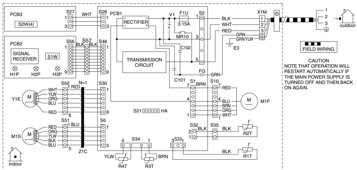
flowchart
graph TD
    subgraph Power Supply
        A["PCB3 S2W(4)"] --> B["S27"]
        B --> C["WHT"]
        C --> D["S26"]
        D --> E["PCB1"]
        E --> F["RECTIFIER"]
        F --> G["V1 F1U 3.15A"]
        G --> H["S2"]
        H --> I["X1M"]
        I --> J["FIELD WIRING."]
        K["PCB2 SIGNAL RECEIVER H1P H2P S1W H3P"] --> L["S56"]
        L --> M["BLK"]
        M --> N["S46"]
        N --> O["TRANSMISSION CIRCUIT"]
        O --> P["C102"]
        P --> Q["FG"]
        Q --> R["GRN"]
        R --> S["X1M"]
        T["Y1E M"] --> U["WHT"]
        U --> V["YLW"]
        V --> W["ORG"]
        W --> X["BLU"]
        X --> Y["RED"]
        Y --> Z["6"]
        Z --> AA["S50"]
        AA --> AB["N=1"]
        AC["M1S M"] --> AD["RED"]
        AD --> AE["ORG"]
        AE --> AF["YLW"]
        AF --> AG["BLK"]
        AG --> AH["BLU"]
        AH --> AI["Z1C"]
        AI --> AJ["S51"]
        AJ --> AK["BLU"]
        AL[" indoor "] --> AM["S30"]
        AM --> AN["S21"]
        AN --> AO["HA"]
    end
    style Power Supply fill:#f9f,stroke:#333
    note right of A: CAUTION NOTE THAT OPERATION WILL RESTART AUTOMATICALLY IF THE MAIN POWER SUPPLY IS TURNED OFF AND THEN BACK ON AGAIN.
    note right of A: FIELD WIRING.
    note right of A: outdoor
    note right of A: FIELD WIRING.
    note right of A: FIELD WIRING.
    note right of A: FIELD WIRING.
    note right of A: FIELD WIRING.
    note right of A: FIELD WIRING.
    note right of A: FIELD WIRING.
    note right of A: FIELD WIRING.
    note right of A: FIELD WIRING.
    note right of A: FIELD WIRING.
    note right of A: FIELD WIRING.

    %% Legend
    subgraph Power Supply
        direction TB
        direction LR
        direction SL
        direction BT
        direction BT
        direction LR
        direction SL
        direction BT
    end
| ⊕ | : | PROTECTIVE EARTH |
| F1U | : | FUSE |
| H1P~H3P | : | PILOT LAMP |
| M1F | : | FAN MOTOR |
| M1S | : | SWING MOTOR |
| PCB1~PCB3 | : | PRINTED CIRCUIT BOARD |
| R1T~R4T | : | THERMISTOR |
| S1~S57 | : CONNECTOR |
| S1W | : OPERATION SWITCH |
| S2W(4) | : UPWARD AIR FLOW LIMIT SWITCH |
| X1M | : TERMINAL STRIP |
| E3 | : EARTH TERMINAL(HEAT EX.) |
| Y1E | : ELECTRONIC EXPANSION VALVE COIL |
| Z1C | : FERRITE CORE |
3D069838A
FVXS25/35/50FV1B
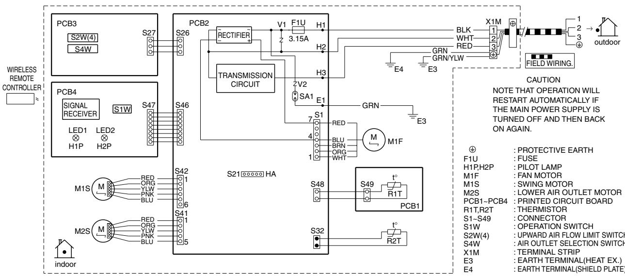
text_image
WIRELESS REMOTE CONTROLLER PCB3 S2W(4) S4W PCB4 S1W LED1 H1P LED2 H2P S46 S47 S21 HA S26 S27 PCB2 RECTIFIER V1 F1U H1 3.15A Z TRANSMISSION CIRCUIT H2 V2 SA1 E1 E3 GRN BLU BRN WHT RED BLU ORG M1F S48 S49 R1T PCB1 S32 t° R2T INDOOR M1S M RED ORG YLW PNK BLU S42 1 M2S M RED ORG YLW PNK BLU S41 1 CAUTION NOTE THAT OPERATION WILL RESTART AUTOMATICALLY IF THE MAIN POWER SUPPLY IS TURNED OFF AND THEN BACK ON AGAIN. ●: PROTECTIVE EARTH F1U FUSE H1P,H2P PILOT LAMP M1F FAN MOTOR M1S SWING MOTOR M2S LOWER AIR OUTLET MOTOR PCB1~PCB4 PRINTED CIRCUIT BOARD R1T,R2T THERMISTOR S1~S49 CONNECTOR S1W OPERATION SWITCH S2W(4) UPWARD AIR FLOW LIMIT SWITCH S4W AIR OUTLET SELECTION SWITCH- X1M TERMINAL STRIP E3 EARTH TERMINAL(HEAT EX.) E4 EARTH TERMINAL(SHIELD PLATE)3D055953A
2.2.3 Floor / Ceiling Suspended Dual Type
FLXS25/35/50/60BAVMB
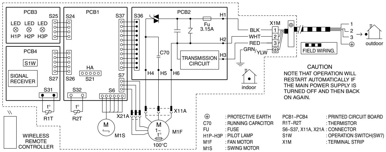
text_image
PCB3 LED LED LED H1P H2P H3P S25 S24 PCB1 S37 S36 PCB2 Fu 3.15A H1 BLK WHT RED GRN/YLW X1M FIELD WIRING. 1 2 3 + outdoor PCB4 S1W S27 S26 HA S21 TRANSMISSION CIRCUIT H2 indoor S31 R1T R2T S32 S6 X21A X11A M1F M1S 100°C X1M PROTECTIVE EARTH PCB1-PCB4 : PRINTED CIRCUIT BOARD C70 : RUNNING CAPACITOR R1T-R2T THERMISTOR FU : FUSE S6~S37, X11A, X21A : CONNECTOR H1P-H3P : PILOT LAMP S1W : OPERATION SWITCH(SW7) M1F : FAN MOTOR X1M : TERMINAL STRIP M1S : SWING MOTOR3D033909F
2.2.4 Duct Connected Type
FDXS25/35E7VMB, FDXS50/60C7VMB
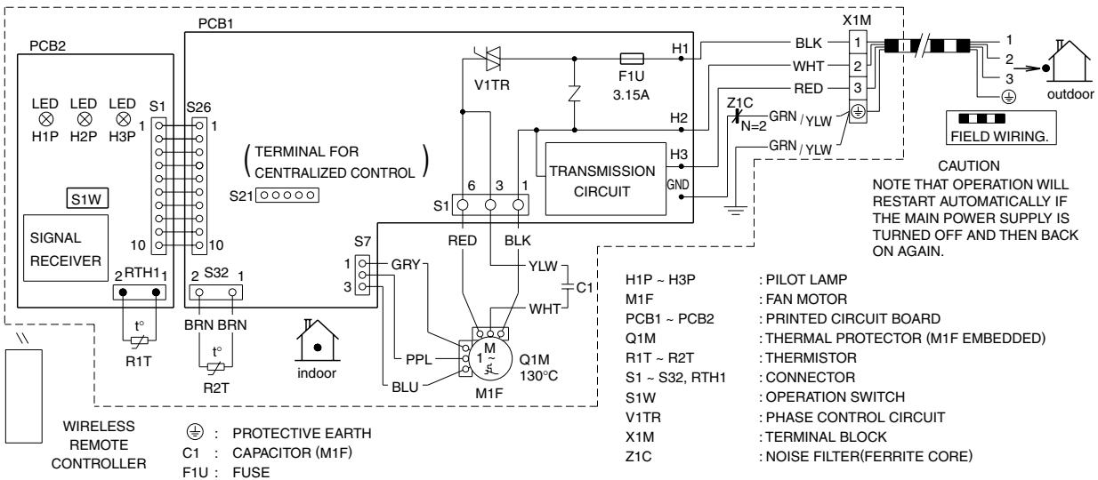
text_image
PCB2 LED H1P LED H2P S1 H3P S1W S1W SIGNAL RECEIVER 10 2 RTH11 10 10 10 10 10 10 10 10 10 10 10 10 10 10 10 10 10 10 10 10 10 10 10 10 10 10 10 10 10 10 10 10 10 10 R1T BRN BRN R2T indoor PCB1 (TERMINAL FOR CENTRALIZED CONTROL) S26 S21 S7 GRY RED BLK YLW C1 PPL M Q1M BLU M1F TRANSMISSION CIRCUIT H1 F1U 3.15A H2 H3 GND X1M BLK 1 WHT 2 RED 3 GRN / YLW GRN / YLW Z1C N=2 NOTE THAT OPERATION WILL RESTART AUTOMATICALLY IF THE MAIN POWER SUPPLY IS TURNED OFF AND THEN BACK ON AGAIN. FIELD WIRING. CAUTION H1P ~ H3P : PILOT LAMP M1F : FAN MOTOR PCB1 ~ PCB2 : PRINTED CIRCUIT BOARD Q1M : THERMAL PROTECTOR (M1F EMBEDDED) R1T ~ R2T : THERMISTOR S1 ~ S32, RTH1 : CONNECTOR S1W : OPERATION SWITCH V1TR : PHASE CONTROL CIRCUIT X1M : TERMINAL BLOCK Z1C : NOISE FILTER(FERRITE CORE) WIRELESS REMOTE CONTROLLER ⊕: PROTECTIVE EARTH C1 : CAPACITOR (M1F) F1U : FUSE3D045012M
2.2.5 Ceiling Mounted Cassette Type
FCQG35/50/60FVEB
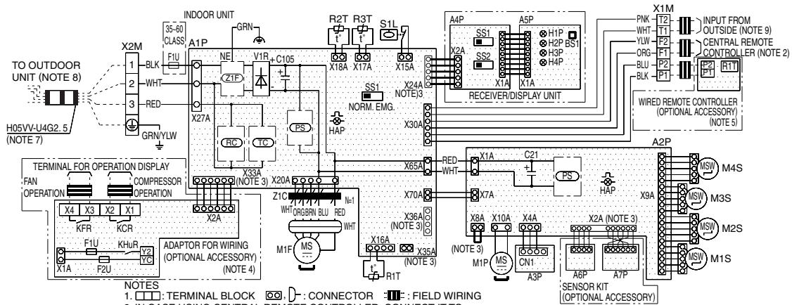
text_image
INDOOR UNIT X2M 35-60 CLASS 1 BLK WHT RED GRN/YLW A1P F1U Z1F V1R C105 X27A RC TC X33A (NOTE 3) X20A Z1C ORGBRN BLU RED WHT ADAPTOR FOR WIRING (NOPTIONAL ACCESSORY) (NOTE 4) X18A X17A X15A PS HAP X65A RED WHT X70A X36A (NOTE 3) X16A X35A (NOTE 3) MS R1T M1F MS A3P A6P A7P SENSOR KIT (OPTIONAL ACCESSORY) X1M T2 WHT-T1 YLV-P2 ORG-F1 BLU-P2 BLK-P1 INPUT FROM OUTSIDE (NOTE 9) CENTRAL REMOTE CONTROLLER (NOTE 2) WIRED REMOTE CONTROLLER (OPTIONAL ACCESSORY) (NOTE 5) A4P SS1 H1P SS2 H2P BS1 H3P H4P RECEIVER/DISPLAY UNIT X2A SS2 X1A X1A X24A NOTE/3 X30A X1A C21 PS HAP X8A X10A X4A X2A (NOTE 3) M1P MS CN1 A3P MSW M4S M3S MSW M2S MSW M1S A2P MSW M4S M3S MSW M2S MSW M1S TO OUTDOOR UNIT (NOTE 8) H05VV-U4G2.5 (NOTE 7) TERMINAL FOR OPERATION DISPLAY FAN OPERATION COMPRESSOR OPERATION KFR KCR F1U KHUR Y2 YC NOTES: TERMINAL BLOCK : CONNECTOR : FIELD WIRING- IN CASE USING CENTRAL REMOTE CONTROLLER, CONNECT IT TO THE UNIT IN ACCORDANCE WITH THE ATTACHED INSTALLATION MANUAL.
- X2A, X8A, X33A, X35A, X36A ARE CONNECTED WHEN THE OPTIONAL ACCESSORIES ARE BEING USED. IN CASE OF USING AN AUTO CLEAN PANEL, SEE THE WIRING DIAGRAM OF IT.
-
CONNECT POWER OF ADAPTOR FOR WIRING TO TERMINAL BLOCK (X2M) OF INDOOR UNIT DIRECTLY.
-
IN CASE OF MAIN/SUB OVERCHANGE, SEE THE INSTALLATION MANUAL ATTACHED TO REMOTE CONTROLLER.
-
SYMBOLS SHOWS AS FOLLOWS : RED : RED BLK : BLACK WHT : WHITE YLW : YELLOW GRN : GREEN ORG : ORANGE BRN : BROWN PNK : PINK GRY : GRAY BLU : BLUE
-
SHOWS ONLY IN CASE OF PROTECTED PIPES. USE H07RN-F IN CASE OF NO PROTECTION.
-
FOR THE DETAIL, SEE WIRING DIAGRAM ATTACHED TO OUTDOOR UNIT.
-
WHEN CONNECTING THE INPUT WIRES FROM OUTSIDE, FORCED OFF OR ON/OFF CONTROL OPERATION CAN BE SELECTED BY THE REMOTE CONTROLLER. SEE INSTALLATION MANUAL FOR MORE DETAILS.
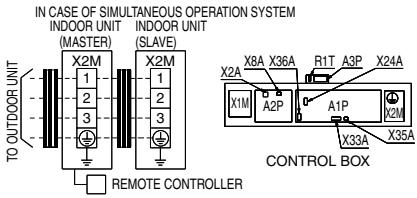
text_image
IN CASE OF SIMULTANEOUS OPERATION SYSTEM INDOOR UNIT (MASTER) INDOOR UNIT (SLAVE) X2M 1 2 3 X2M 1 2 3 X8A X36A R1T A3P X24A X1M A2P A1P X2M X33A X35A CONTROL BOX TO OUTDOOR UNIT REMOTE CONTROLLER| INDOOR UNIT | RECEIVER/DISPLAY UNIT (ATTACHED TO WIRELESS REMOTE CONTROLLER) | CONNECTOR FOR OPTIONAL PARTS | |||
| A1P | PRINTED CIRCUIT BOARD | X2A | CONNECTOR (SENSOR KIT) | ||
| A2P | PRINTED CIRCUIT BOARD | ||||
| A3P | PRINTED CIRCUIT BOARD | PRINTED CIRCUIT BOARD | X8A | CONNECTOR (AUTO CLEAN PANEL) | |
| (HUMIDITY SENSOR UNIT) | A4P | PRINTED CIRCUIT BOARD | |||
| C21 | CAPACITOR | A5P | PUSH BUTTON (ON/OFF) | X24A | CONNECTOR (WIRELESS REMOTE CONTROLLER) |
| C105 | CAPACITOR | BS1 | LIGHT EMITTING DIODE (ON-RED) | ||
| F1U | FUSE (F, 5A, 250V) | H1P | X33A | CONNECTOR (ADAPTOR FOR WIRING) | |
| HAP | LIGHT EMITTING DIODE (SERVICE MONITOR GREEN) | H2P | LIGHT EMITTING DIODE (TIMER-GREEN) | X35A | CONNECTOR (GROUP CONTROL ADAPTOR) |
| H3P | LIGHT EMITTING DIODE (FILTER SIGN-RED) | X36A | CONNECTOR (AUTO CLEAN PANEL) | ||
| M1F | MOTOR (INDOOR FAN) | ||||
| M1P | MOTOR (DRAIN PUMP) | LIGHT EMITTING DIODE (DEFROST-ORANGE) | |||
| M1S-M4S | MOTOR (SWING FLAP) | H4P | |||
| R1T | THERMISTOR (AIR) | SS1 | SELECTOR SWITCH (MAIN/SUB) | ||
| R2T-R3T | THERMISTOR (COIL) | ||||
| S1L | FLOAT SWITCH | SS2 | SELECTOR SWITCH (WIRELESS ADDRESS SET) | ||
| SS1 | SELECTOR SWITCH (EMERGENCY) | ||||
| V1R | DIODE BRIDGE | ADAPTOR FOR WIRING | |||
| X1M | TERMINAL BLOCK | F1U | FUSE (B, 5A, 250V) | ||
| X2M | TERMINAL BLOCK | F2U | |||
| Z1C | FERRITE CORE (NOISE FILTER) | KCR | MAGNETIC RELAY | ||
| KFR | MAGNETIC RELAY | ||||
| (Z1F) | NOISE FILTER | KHuR | MAGNETIC RELAY (Hu) | ||
| (PS) | POWER SUPPLY CIRCUIT | ||||
| (RC) | SIGNAL RECEIVER CIRCUIT | ||||
| (TC) | SIGNAL TRANSMISSION CIRCUIT | ||||
| WIRED REMOTE CONTROLLER | |||||
| R1T | THERMISTOR (AIR) | ||||
3D074344
FFQ25/35/50/60B9V1B
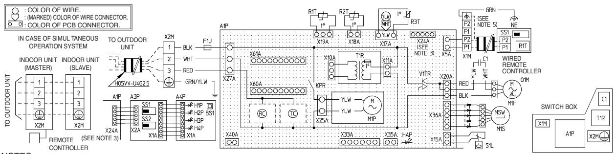
text_image
COLOR OF WIRE. (MARKED) COLOR OF WIRE CONNECTOR. COLOR OF PCB CONNECTOR. IN CASE OF SIMUL TANEOUS OPERATION SYSTEM INDOOR UNIT (MASTER) INDOOR UNIT (SLAVE) TO OUTDOOR UNIT H05VV-U4G25 A1P A3P SS1 SS2 X2A X1A A4P HIP H2P BS1 H3P H4P X1A X61A WHT RED GRN/YLW F1U X27A X60A RC TC X40A X33A X35A HAP X19A X18A X17A X10A T1R X11A X24A (SEE NOTE 3) X5A V1TR X20A RED BLK X36A MSW MIS SIL GRN (SEE NOTE 5) NE F1 P2 P1 CS1 P2 P1 WIRED REMOTE CONTROLLER QIM MIF M1F SWITCH BOX C1 T1R X1M A1P REMOTE CONTROLLERNOTES:
- IN CASE OF USING A REMOTE CONTROLLER, CONNECT IT TO THE UNIT IN ACCORDANCE TO THE ATTACHED INSTALLATION MANUAL.
- X24A IS CONNECTED WHEN THE WIRELESS REMOTE CONTROLLER KIT IS BEING USED.
- REMOTE CONTROLLER MODEL VARIES ACCORDING TO THE COMBINATION SYSTEM.
SEE TECHNICAL DATA AND CATALOGS, ETC. BEFORE CONNECTING.
(IN CASE OF USING SHIELD WIRE)
□□□ : TERMINAL
: CONNECTOR
: WIRE CLAMP
≡ : FIELD WIRING
RED: RED
BLK: BLACK
WHT: WHITE
YLW: YELLOW
GRN: GREEN
| A1P | PRINTED CIRCUIT BOARD | WIRED REMOTE CONTROLLER | WIRELESS REMOTE CONTROLLER (RECEIVER/DISPLAY UNIT) | CONNECTOR FOR OPTIONAL PARTS | |||
| C1 | CAPACITOR (M1F) | R1T | THERMISTOR (AIR) | X33A | CONNECTOR (ADAPTOR FOR WIRING) | ||
| F1U | FUSE (F5A, 250V) | SS1 | SELECTOR SWITCH (MAIN/SUB) | A3P | PRINTED CIRCUIT BOARD | ||
| HAP | LIGHT EMITTING DIODE (SERVICE MONITOR GREEN) | A4P | PRINTED CIRCUIT BOARD | X35A | CONNECTOR (GROU CONTROL ADAPTOR) | ||
| BS1 | PUSH BUTTON(ON/OFF) | ||||||
| KPR | MAGNETIC RELAY (M1P) | H1P | LIGHT EMITTING DIODE (ON-RED) | X40A | CONNECTOR (ON/OFF INPUT FROM OUTSIDE) | ||
| M1F | MOTOR (INDOOR FAN) | ||||||
| M1P | MOTOR (DRAIN PUMP) | H2P | LIGHT EMITTING DIODE (TIMER-GREEN) | X60A X61A | CONNECTOR (INTERFACE ADAPTOR FOR SKY-AIR SERIES) | ||
| M1S | MOTOR (SWING FLAP) | ||||||
| Q1M | THERMO SWITCH (M1F EMBEDDED) | H3P | LIGHT EMITTING DIODE (FILTER SIGN-RED) | ||||
| R1T | THERMISTOR (AIR) | H4P | LIGHT EMITTING DIODE (DEFROST-ORANGE) | ||||
| R2T | THERMISTOR (COIL-1) | ||||||
| R3T | THERMISTOR (COIL-2) | SS1 | SELECTOR SWITCH (MAIN/SUB) | ||||
| S1L | FLOAT SWITCH | ||||||
| T1R | TRANSFORMER (220-240V/22V) | SS2 | SELECTOR SWITCH (WIRELESS ADDRESS SET) | ||||
| V1TR | PHASE CONTROL CIRCUIT | ||||||
| X1M | TERMINAL STRIP | ||||||
| X2M | TERMINAL STRIP | ||||||
| RC | SIGNAL RECEIVER CIRCUIT | ||||||
| TC | SIGNAL TRANSMISSION CIRCUIT | ||||||
3TW26476-1
2.2.6 Ceiling Suspended Type
FHQ35/50/60BWV1B
text_image
A1P PRINTED CIRCUIT BOARD SS1 RUSH BUTTON SWITCH (ON/OFF) C1 CAPACITOR (M/F) H1P PILOT LAMP F1U FUSE (F5A 250V) HAP FLASHING LAMP H2P PILOT LAMP (SERVICE MONITOR GREEN) (ON-RED) KAR MAGNETIC RELAY (M/S) H3P PILOT LAMP KPR MAGNETIC RELAY (M/P) H4P PILOT LAMP M1F MOTOR (INDOOR FAN) H4P PILOT LAMP M1S MOTOR (SWING FLAP) DEPROTOR Q1M THERMISTOR (M/F EMBEDDED) SS1 SELECTOR SWITCH R1T THERMISTOR (AIR) SS2 SELECTOR SWITCH R2T THERMISTOR (COIL-1) SS2 SELECTOR SWITCH R3T THERMISTOR (COIL-2) SS2 WIRELESS ADDRESS SET S1C LIMIT SWITCH (SWING FLAP) CONNECTOR FOR OPTIONAL PARTS SS1 SELECTOR SWITCH (EVERGENCY) X15A CONNECTOR (FLOAT SWITCH) T1R TRANSFORMER (220-240V/22V) X24A CONNECTOR V1TR TRIAC (PHASE CONTROL CIRCUIT) X25A CONNECTOR (DRAIN PUMP) X1M TERMINAL BLOCK X25A CONNECTOR (DRAIN PUMP) X2M TERMINAL BLOCK X33A CONNECTOR (ADAPTOR FOR WIRING) RC SIGNAL RECEIVER CIRCUIT X35A CONNECTOR TC SIGNAL TRANSMISSION CIRCUIT X40A CONNECTOR Wired REMOTE CONTROLLER X40A CONNECTOR R1T THERMISTOR (AIR) X60A CONNECTOR (ON/OFF INPUT FROM OUTSIDE) SS1 SELECTOR SWITCH (MAINSUB) X60A CONNECTOR (INTERFACE ADAPTOR WIRELESS REMOTE CONTROLLER X61A CONNECTOR (FOR SKY AIR SERIES) A2P PRINTED CIRCUIT BOARD X15A A1P C1 T1R A3P PRINTED CIRCUIT BOARD X19A X2M X3M X2M CONTROL BOX IN CASE OF SIMULTANEOUS OPERATION SYSTEM (NOTE 6) INDOOR UNIT INDOOR UNIT (MASTER) SLAVE TO OUTDOOR UNIT TO OUTDOOR UNIT UNIT (NOTE 4) X2M 1 BLK 1 2 3 4 5 NOTE 10) H05VV-U4G2.5 REMOTE CONTROLLER NOTES NOTES 1. TERMINAL BLOCK 2. CONNECTOR 3. SHORT CIRCUIT CONNECTOR 4. CONNECTOR 2. FIELD WIRING 3. IN CASE OF SIMULTANEOUS OPERATION INDOOR UNIT SYSTEM. SEE THE INDOOR UNIT WIRING ONLY. 4. FOR THE DETAIL. SEE WIRING DIAGRAM ATTACHED TO OUTDOOR UNIT. 5. IN CASE USING CENTRAL REMOTE CONTROLLER, CONNECT IT TO THE UNIT IN ACCORDANCE WITH THE ATTACHED INSTALLATION MANUAL. 6. IN CASE OF CONNECTION UNITS VARIES ACCORDING TO THE COMBINATION SYSTEM. CONFIRM TECHNICAL GUIDE AND CATALOGS, ETC. BEFORE CONNECTING. 7. IN CASE OF MAINSUB CHANGEOVER. SEE THE INSTALLATION MANUAL ATTACHED TO REMOTE CONTROLLER. NOTE 8 NOTE 7 NOTE 6 NOTE 5 NOTE 4 NOTE 3 NOTE 2 NOTE 1 NOTE 0 NOTE 9 NOTE 8 NOTE 7 NOTE 6 NOTE 5 NOTE 4 NOTE 3 NOTE 2 NOTE 1 NOTE 0 NOTE 9 NOTE 8 NOTE 7 NOTE 6 NOTE 5 NOTE 4 NOTE 3 NOTE 2 NOTE 1 NOTE 0 NOTE 9 NOTE 83D074574A
2.2.7 Ceiling Mounted Built-in Type
FDBQ25B8V1
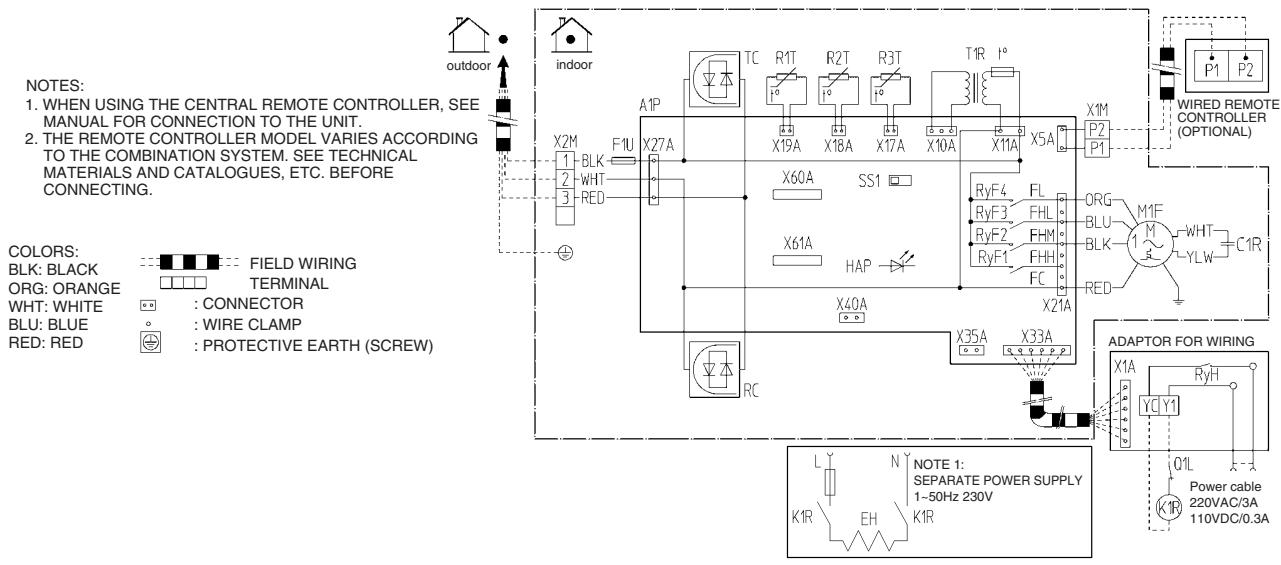
text_image
NOTES: 1. WHEN USING THE CENTRAL REMOTE CONTROLLER, SEE MANUAL FOR CONNECTION TO THE UNIT. 2. THE REMOTE CONTROLLER MODEL VARIES ACCORDING TO THE COMBINATION SYSTEM. SEE TECHNICAL MATERIALS AND CATALOGUES, ETC. BEFORE CONNECTING. COLORS: BLK: BLACK ORG: ORANGE WHT: WHITE BLU: BLUE RED: RED FIELD WIRING TERMINAL : CONNECTOR : WIRE CLAMP : PROTECTIVE EARTH (SCREW) NOTE 1: SEPARATE POWER SUPPLY 1-50Hz 230V RC X2M 1 2 3 BLK WHT RED A1P F1U X27A X60A SS1 X61A HAP X40A X35A X33A RC TC R1T R2T R3T T1R T5A X19A X18A X17A X10A X11A X5A X1M P2 P1 WIRED REMOTE CONTROLLER (OPTIONAL) ORG BLU BLK M1F YLW C1R ADAPTOR FOR WIRING X1A YC Y1 RYH Q1L Power cable 220VAC/3A 110VDC/0.3A| A1P | PRINTED CIRCUIT BOARD | R1T | THERMISTOR (AIR) | ADAPTOR FOR WIRING | FIELD SUPPLY | ||
| T1R | POWER SUPPLY TRANSFORMER (TRANSFORMER 220-240V/218V) | R2T | THERMISTOR (LIQUID) | RyH | MAGNETIC RELAY | K1R | MAGNETIC RELAY |
| R3T | THERMISTOR (COIL) | Q1L | THERMAL PROTECTOR | EH | ELECTRICAL HEATER KIT | ||
| C1R | CAPACITOR (FAN) | RyF1-4 | MAGNETIC RELAY (FAN) | CONNECTOR FOR OPTIONAL PARTS | |||
| F1U | FUSE (5A, 250V) | SS1 | SELECTOR SWITCH (EMERGENCY) | X60A, X61A | CONNECTOR (INTERFACE ADAPTOR FOR SKY AIR/US SERIES) | ||
| F1T | THERMAL FUSE (152°C) (M1F EMBEDDED) | X1M | TERMINAL STRIP | ||||
| X2M | TERMINAL STRIP | X33A | CONNECTOR (ADAPTOR FOR WIRING) | ||||
| HAP | LIGHT EMITTING DIODE (SERVICE MONITOR-GREEN) | RC | SIGNAL RECEIVER CIRCUIT | X35A | CONNECTOR (GROUP CONTROL ADAPTOR) | ||
| TC | SIGNAL TRANSMISSION CIRCUIT | X40A | CONNECTOR (REMOTE ON/OFF FORCED OFF) | ||||
| M1F | MOTOR (FAN) | ||||||
2TW25856-1B
FBQ35/50C8VEB
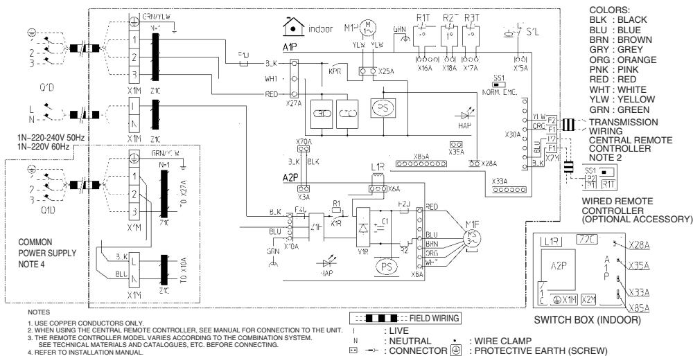
text_image
COLORS: BLK : BLACK BLU : BLUE BRN : BROWN GRY : GREY ORG : ORANGE PNK : PINK RED : RED WHT : WHITE YLW : YELLOW GRN : GREEN TRANSMISSION WIRING CENTRAL REMOTE CONTROLLER NOTE 2 WIRED REMOTE CONTROLLER (OPTIONAL ACCESSORY) COMMON POWER SUPPLY NOTE 4 NOTES 1. USE COPPER CONDUCTORS ONLY. 2. WHEN USING THE CENTRAL REMOTE CONTROLLER, SEE MANUAL FOR CONNECTION TO THE UNIT. 3. THE REMOTE CONTROLLER MODEL VARIES ACCORDING TO THE COMBINATION SYSTEM. SEE TECHNICAL MATERIALS AND CATALOGUES, ETC. BEFORE CONNECTING. 4. REFER TO INSTALLATION MANUAL. A2P X1M Z1C X1M Z1C X'M 71C X'M TO X10A 3.K BLL Z1C A1P INDOOR M1- M- YLW YLW R1T R2- R3T X6A X8A X7A X5A SS1 NORM LWC X70A X70A X30A X35A X33A X33A X33A X33A X33A X33A X33A X33A X33A X33A X33A X33A X33A X33A X33A X33A X33A X33A X33A X33A X30A BLK BLK BLK BLK BLK BLK BLK BLK BLK BLK BLK BLK BLK BLK BLK BLK BLK BLK BLK BLK BLK BLK BLK BLK BLK BLK BLK BLK BLK BLK BLK BLK BLK BLK| INDOOR UNIT | CONNECTOR OPTIONAL ACCESSORY | WIRED REMOTE CONTROLLER | |||
| A1P | PRINTED CIRCUIT BOARD | X28A | CONNECTOR(POWER SUPPLY FOR WIRING) | R1T | THERMISTOR (AIR) |
| A2P | PRINTED CIRCUIT BOARD (FAN) | SS1 | SELECTOR SWITCH (MAIN/SUB) | ||
| C1 | CAPACITOR | X33A | CONNECTOR (FOR WIRING) | ||
| F1U, F2U | FUSE (T, 5A, 250V) | X35A | CONNECTOR (ADAPTER) | ||
| F4U | FUSE (T, 6.3A, 250V) | X85A | CONNECTOR (FOR MULTI ZONING) | ||
| HAP | LIGHT EMITTING DIODE(SERVICE MONITOR-GREEN) | ||||
| KPR, K1R | MAGNETIC RELAY | ||||
| L1R | REACTOR | ||||
| M1F | MOTOR (FAN) | ||||
| M1P | MOTOR (DRAIN PUMP) | ||||
| PS | SWITCHING POWER SUPPLY | ||||
| Q1DI | EARTH LEAK DETECTOR | ||||
| R1 | RESISTOR (CURRENT LIMITING) | ||||
| R2 | CURRENT SENSING DEVICE | ||||
| R1T | THERMISTOR (SUCTION AIR) | ||||
| R2T | THERMISTOR (LIQUID) | ||||
| R3T | THERMISTOR (COIL) | ||||
| SS1 | SELECTOR SWITCH (EMERGENCY) | ||||
| S1L | FLOAT SWITCH | ||||
| V1R | DIODE BRIDGE | ||||
| V2R | POWER MODULE | ||||
| X1M | TERMINAL STRIP (POWER SUPPLY) | ||||
| X2M | TERMINAL STRIP (CONTROL) | ||||
| Z1C | NOISE FILTER (FERRITE CORE) | ||||
| Z1F | NOISE FILTER | ||||
| CBO | SIGNAL RECEIVER CIRCUIT | ||||
| CTO | SIGNAL TRANSMISSION CIRCUIT | ||||
2TW31276-1A
FBQ60C8VEB
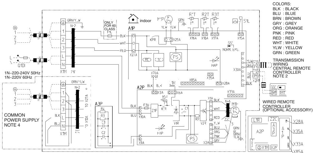
text_image
1N-220-240V 50Hz 1N-220V 60Hz COMMON POWER SUPPLY NOTE 4 GRN/YLW N=2 TO X27A + BLK BLJ X1M N Z+C X1M N=2 TO X27A + A3P R4 R3 C3 C2 X1M ONLY FOR 60 CLASS FTL GLND INDOOR A1P INDOOR M P YLW YLW GPN R' T R' T R3 T X16A X18A X17A X15A KPR X25A X70A X90A X35A HAP X30A X85A X28A A2P BLK F3U Z1F X3A X6A X10A X1A BLK R3T Y+W R2T R2T R3T X10A X1A R3T R3T X10A X1A R3T R3T X10A X1A R3T R3T X10A X1A R3T R3T X10A X1A R3T R3T X10A X1A R3T R3T X10A X1ANOTES:
1. USE COPPER CONDUCTORS ONLY
2. WHEN USING THE CENTRAL REMOTE CONTROLLER, SEE MANUAL FOR CONNECTION TO THE UNIT.
3. THE REMOTE CONTROLLER MODEL VARIES ACCORDING TO THE COMBINATION SYSTEM. SEE
TECHNICAL MATERIALS AND CATALOGUES, ETC. BEFORE CONNECTING.
4. REFER TO INSTALLATION MANUAL
| INDOOR UNIT | |
| A1P | PRINTED CIRCUIT BOARD |
| A2P | PRINTED CIRCUIT BOARD (FAN) |
| A3P | PRINTED CIRCUIT BOARD (CAPACITOR) |
| C1, C2, C3 | CAPACITOR |
| F1U | FUSE (T.5A,250V) |
| F3U | FUSE (T.6,3A,250V) |
| HAP | LIGHT EMITTING DIODE(SERVICE MONITOR-GREEN) |
| KPR, K1R | MAGNETIC RELAY |
| L1R | REACTOR |
| M1F | MOTOR (FAN) |
| M1P | MOTOR (DRAIN PUMP) |
| PS | SWITCHING POWER SUPPLY |
| Q1DI | EARTH LEAK DETECTOR |
| R2 | CURRENT SENSING DEVICE |
| R3, R4 | RESISTOR (ELECTRIC DISCHARGE) |
| R1T | THERMISTOR (SUCTION AIR) |
| R2T | THERMISTOR (LIQUID) |
| R3T | THERMISTOR (COIL) |
| R5T | THERMISTOR NTC (CURRENT LIMITING) |
| SS1 | SELECTOR SWITCH (EMERGENCY) |
| S1L | FLOAT SWITCH |
| V1R | DIGOC BRIDGE |
| V2R | POWER MODULE |
| X1M | TERMINAL STRIP (POWER SUPPLY) |
| X2M | TERMINAL STRIP (CONTROL) |
| Z1C, Z2C | NOISE FILTER (FERRITE CORE) |
| V1F | NOISE FILTER |
| CIO | SIGNAL RECEIVER CIRCUIT |
| CIO | SIGNAL TRANSMISSION CIRCUIT |

| · LIVE
- LIVE
- NEUTRAL
N : NEUTRAL
→: CONNECTOR
[Non-Text]
• WIRE CLAMP
:
PROTECTIVE EARTH (SCREW)
| INDOOR UNIT | |
| A1P | PRINTED CIRCUIT BOARD |
| A2P | PRINTED CIRCUIT BOARD (FAN) |
| A3P | PRINTED CIRCUIT BOARD (CAPACITOR) |
| C1, C2, C3 | CAPACITOR |
| F1U | FUSE (T.5A,250V) |
| F3U | FUSE (T.6,3A,250V) |
| HAP | LIGHT EMITTING DIODE(SERVICE MONITOR-GREEN) |
| KPR, K1R | MAGNETIC RELAY |
| L1R | REACTOR |
| M1F | MOTOR (FAN) |
| M1P | MOTOR (DRAIN PUMP) |
| PS | SWITCHING POWER SUPPLY |
| Q1DI | EARTH LEAK DETECTOR |
| R2 | CURRENT SENSING DEVICE |
| R3, R4 | RESISTOR (ELECTRIC DISCHARGE) |
| R1T | THERMISTOR (SUCTION AIR) |
| R2T | THERMISTOR (LIQUID) |
| R3T | THERMISTOR (COIL) |
| R5T | THERMISTOR NTC (CURRENT LIMITING) |
| SS1 | SELECTOR SWITCH (EMERGENCY) |
| S1L | FLOAT SWITCH |
| V1R | DIGOC BRIDGE |
| V2R | POWER MODULE |
| X1M | TERMINAL STRIP (POWER SUPPLY) |
| X2M | TERMINAL STRIP (CONTROL) |
| Z1C, Z2C | NOISE FILTER (FERRITE CORE) |
| V1F | NOISE FILTER |
| CIO | SIGNAL RECEIVER CIRCUIT |
| CIO | SIGNAL TRANSMISSION CIRCUIT |
2TW31296-3
- Daikin products are manufactured for export to numerous countries throughout the world. Prior to purchase, please confirm with your local authorised importer, distributor and/or retailer whether this product conforms to the applicable standards, and is suitable for use, in the region where the product will be used. This statement does not purport to exclude, restrict or modify the application of any local legislation.
- Ask a qualified installer or contractor to install this product. Do not try to install the product yourself. Improper installation can result in water or refrigerant leakage, electrical shock, fire or explosion.
- Use only those parts and accessories supplied or specified by Daikin. Ask a qualified installer or contractor to install those parts and accessories. Use of unauthorised parts and accessories or improper installation of parts and accessories can result in water or refrigerant leakage, electrical shock, fire or explosion.
- Read the User's Manual carefully before using this product. The User's Manual provides important safety instructions and warnings. Be sure to follow these instructions and warnings.
If you have any enquiries, please contact your local importer, distributor and/or retailer.
Cautions on product corrosion
- Air conditioners should not be installed in areas where corrosive gases, such as acid gas or alkaline gas, are produced.
- If the outdoor unit is to be installed close to the sea shore, direct exposure to the sea breeze should be avoided. If you need to install the outdoor unit close to the sea shore, contact your local distributor.
Dealer
DAIKIN INDUSTRIES, LTD.
Head Office:
Umeda Center Bldg., 2-4-12, Nakazaki-Nishi,
Kita-ku, Osaka, 530-8323 Japan
Tokyo Office:
JR Shinagawa East Bldg., 2-18-1, Konan,
Minato-ku, Tokyo, 108-0075 Japan
http://www.daikin.com/global_ac/
©All rights reserved