
KOR6LBRR - Home Appliance DAEWOO - Free user manual and instructions
Find the device manual for free KOR6LBRR DAEWOO in PDF.
| Product Type | Microwave Oven |
| Brand | DAEWOO |
| Model | KOR6LBRR |
| Power Supply | 120 V~, 60 Hz, single phase with grounding |
| Input Power | 1100 W |
| Output Power | 700 W |
| Frequency | 2450 MHz |
| External Dimensions (W × H × D) | 44.7 × 26.9 × 32.0 cm |
| Cavity Dimensions (W × H × D) | 29.5 × 21.8 × 30.2 cm |
| Cavity Volume | 0.7 ft³ (19.8 L) |
| Net Weight | approx. 9.5 kg |
| Timer | 59 min 99 s |
| Power Levels | 10 (from 0% to 100%) |
| Main Functions | Cooking, weight and time defrost, clock |
| Safety | Door interlock system, protective screen, door seal |
| Maintenance and Cleaning | Clean the door seal and cavity regularly |
| Included Accessories | Glass turntable, roller guide, coupler |
| Spare Parts and Repairability | Available parts: door, control panel, HV transformer, etc. |
| General Information | User manual and service manual available |
Frequently Asked Questions - KOR6LBRR DAEWOO
User questions about KOR6LBRR DAEWOO
0 question about this device. Answer the ones you know or ask your own.
Ask a new question about this device
Download the instructions for your Home Appliance in PDF format for free! Find your manual KOR6LBRR - DAEWOO and take your electronic device back in hand. On this page are published all the documents necessary for the use of your device. KOR6LBRR by DAEWOO.
USER MANUAL KOR6LBRR DAEWOO
(a) Do not operate or allow the oven to be operated with the door open.
(b) Make the following safety checks on all ovens to be serviced before activating the magnetron or other microwave source, and make repairs as necessary: (1) Interlock operation, (2) Proper door closing, (3) Seal and sealing surfaces (arcing, wear, and other damage), (4) Damage to or loosening of hinges and latches, (5) Evidence of dropping or abuse.
(c) Before turning on microwave power for any service test or inspection within the microwave generating compartments, check the magnetron, wave guide or transmission line, and cavity for proper alignment, integrity, and connections.
(d) Any defective or misadjusted components in the interlock, monitor, door seal, and microwave generation and transmission systems shall be repaired, replaced, or adjusted by procedures described in this manual before the oven is released to the owner.
(e) A microwave leakage check to verify compliance with the Federal performance standard should be performed on each oven prior to release to the owner.
TABLE OF CONTENTS
PRECAUTIONS TO BE OBSERVED BEFORE AND DURING SERVICING TO AVOID POSSIBLE
EXPOSURE TO EXCESSIVE MICROWAVE ENERGY 1
SAFETY AND PRECAUTIONS 2
FOR SAFE OPERATION 2
FOR SAFE SERVICE PROCEDURES 2
SPECIFICATIONS 3
EXTERNAL VIEW 3
OUTER DIMENSION 3
FEATURES DIAGRAM. 4
CONTROL PANEL 5
INSTALLATION 6
OPERATIONS AND FUNCTIONS 7
DISASSEMBLY AND ASSEMBLY 8
INTERLOCK MECHANISM AND ADJUSTMENT 15
TROUBLE SHOOTING GUIDE 16
MEASUREMENT AND TEST 20
MEASUREMENT OF THE MICROWAVE POWER OUTPUT 20
MICROWAVE RADIATION TEST 21
COMPONENT TEST PROCEDURE 22
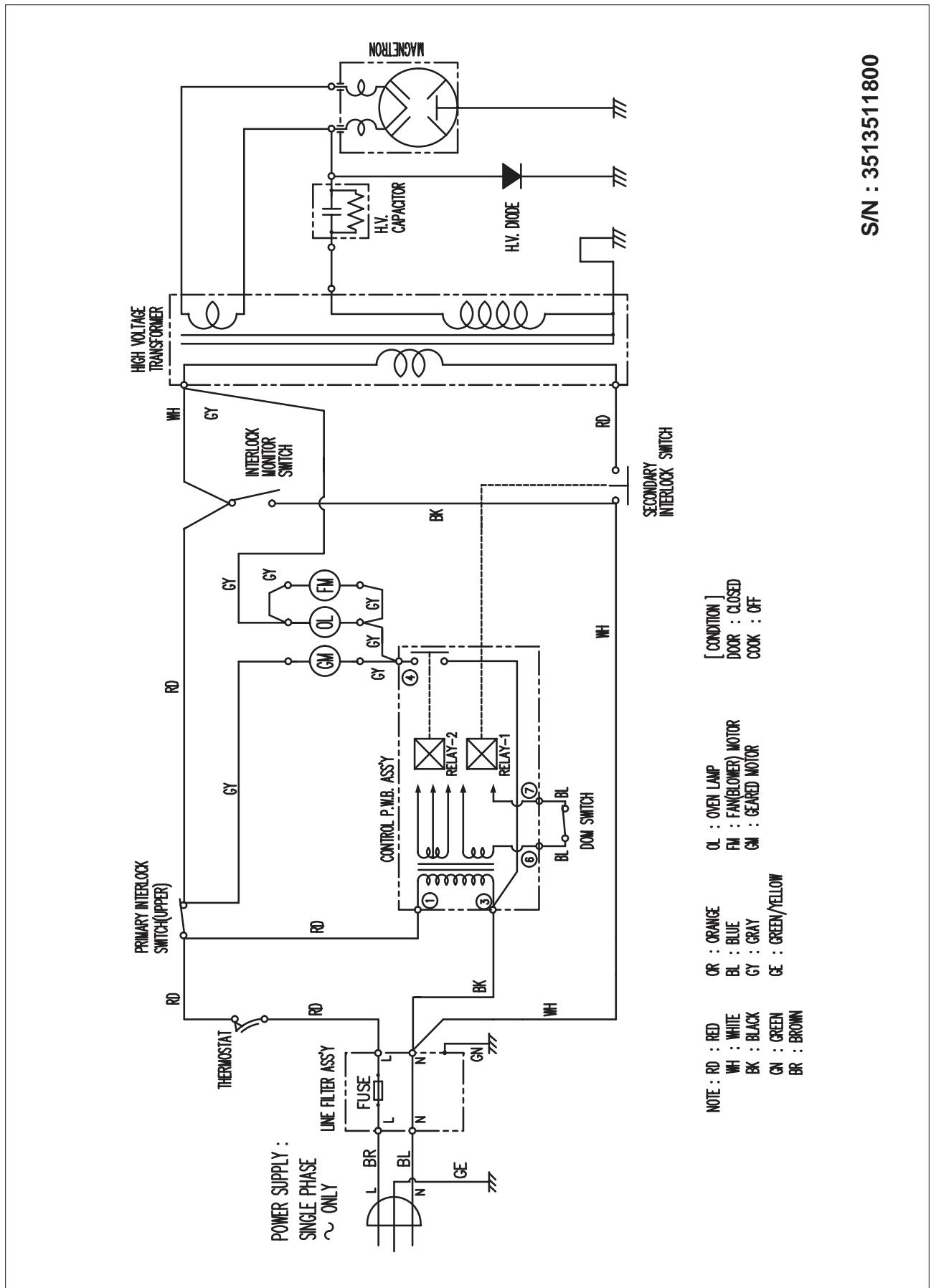
WIRING DIAGRAM 23
PRINTED CIRCUIT BOARD 24
CIRCUIT CHECK PROCEDURE 24
PCB CIRCUIT DIAGRAM 27
PCB LOCATION NO 28
EXPLODED VIEW AND PARTS LIST 29
DOOR ASSEMBLY 29
CONTROL PANEL ASSEMBLY 29
TOTAL ASSEMBLY 29
CAUTION : This Device is to be Serviced Only by Properly Qualified Service Personnel. Consult the Service Manual for Proper Service Procedures to Assure Continued Safety Operation and for Precautions to be Taken to Avoid Possible Exposure to Excessive Microwave Energy.
Damage that allows the microwave energy (that cooks or heats the food) to escape will result in poor cooking and may cause serious bodily injury to the operator.
IF ANY OF THE FOLLOWING CONDITIONS EXIST, OPERATOR MUST NOT USE THE APPLIANCE.
(Only a trained service personnel should make repairs.)
(1) A broken door hinge.
(2) A broken door viewing screen.
(3) A broken front panel, oven cavity.
(4) A loosened door lock.
(5) A broken door lock.
The door gasket plate and oven cavity surface should be kept clean.
No grease, soil or spatter should be allowed to build up on these surfaces or inside the oven.
DO NOT ATTEMPT TO OPERATE THIS APPLIANCE WITH THE DOOR OPEN. The microwave oven has concealed switches to make sure the power is turned off when the door is opened. Do not attempt to by-pass.
DO NOT ATTEMPT TO SERVICE THIS APPLIANCE UNTIL YOU HAVE READ THIS SERVICE MANUAL.
2. FOR SAFE SERVICE PROCEDURES
1) If the oven is operative prior to servicing, a microwave emission check should be performed prior to servicing the oven.
2) If any certified oven unit is found to have excessive emission level 5mW/cm^2 , the service man should :
(a) inform the manufacturer, importer or assembler,
(b) repair the unit at no cost to the owner,
(c) attempt to ascertain the cause of the excessive leakage,
(d) tell the owner of the unit not to use the unit until the oven has been brought into compliance.
3) If the oven operates with the door open, the service person should tell the user not to operate the oven and contact the manufacturer and CDRH immediately.
CAUTION
MICROWAVE RADIATION
PERSONNEL SHOULD NOT BE EXPOSED TO THE MICROWAVE ENERGY WHICH MAY RADIATE FROM THE MAGNETRON OR OTHER MICROWAVE GENERATING DEVICE IF IT IS IMPROPERLY USED OR CONNECTED. ALL INPUT AND OUTPUT MICROWAVE CONNECTIONS. WAVEGUIDES FLANGES AND GASKETS MUST BE SECURED. NEVER OPERATE THE DEVICE WITHOUT A MICROWAVE ENERGY ABSORBING LOAD ATTACHED. NEVER LOOK INTO AN OPEN WAVEGUIDE OR ANTENNA WHILE THE DEVICE IS ENERGIZED.
| POWER SUPPLY | 120V AC, 60Hz SINGLE PHASE WITH GROUNDING | |
| MICROWAVE | INPUT POWER | 1100 W |
| ENERGY OUTPUT | 700 W | |
| FREQUENCY | 2,450MHz | |
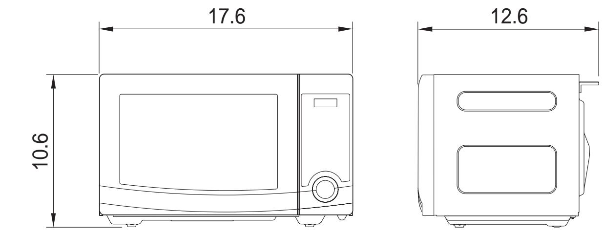
| OUTSIDE DIMENSIONS (W × H × D) | 17.6 x 10.6 x 12.6 in. | |
| CAVITY DIMENSIONS (W × H × D) | 11.6 x 8.6 x 11.9 in. | |
| CAVITY VOLUME | 0.7 cu.ft | |
| NET WEIGHT | APPROX. 21.0 lbs. | |
| TIMER | 59 min. 99 sec. | |
| POWER SELECTIONS | 10 Levels | |
- Specifications are subject to change without notice.
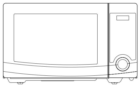
EXTERNAL VIEW
1. OUTER DIMENSION
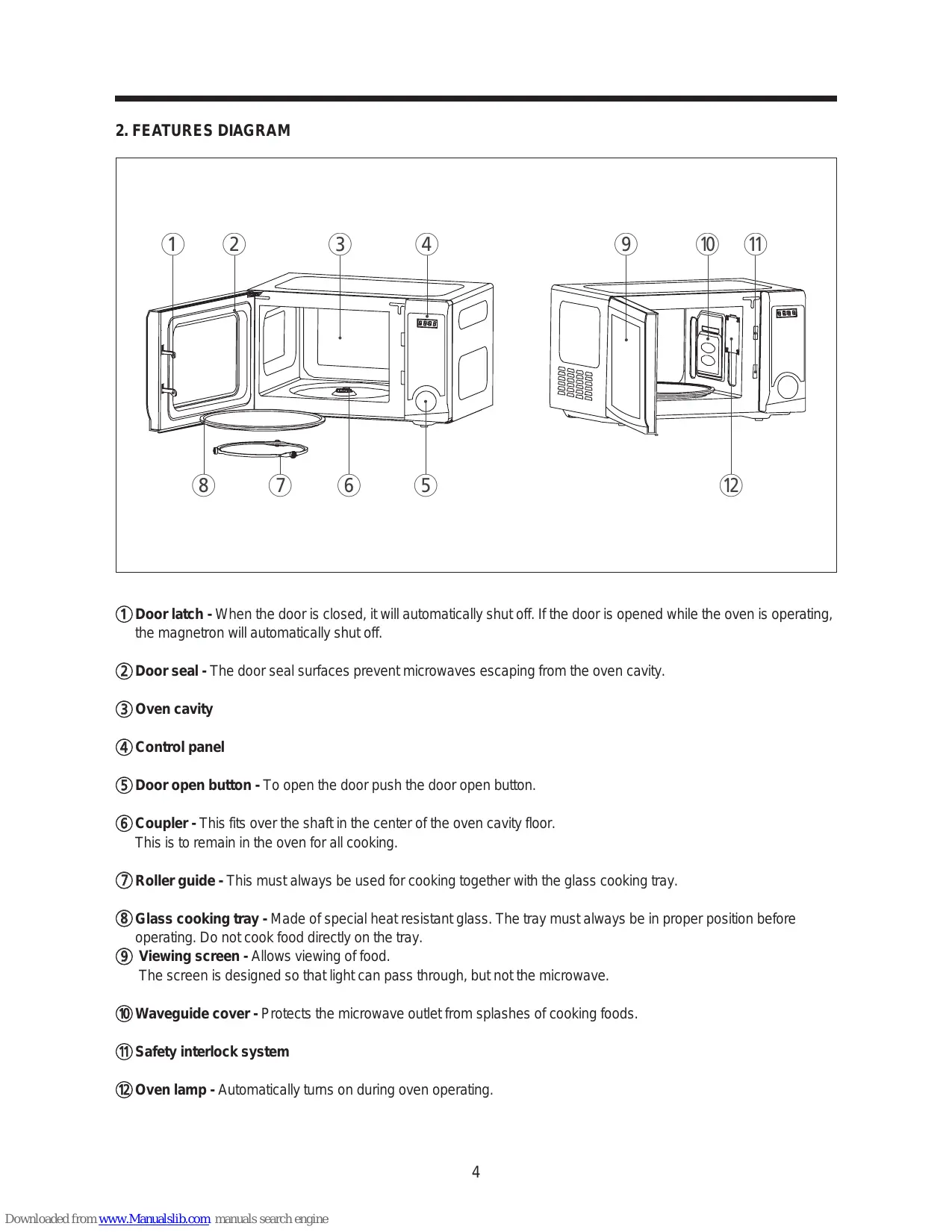
2. FEATURES DIAGRAM
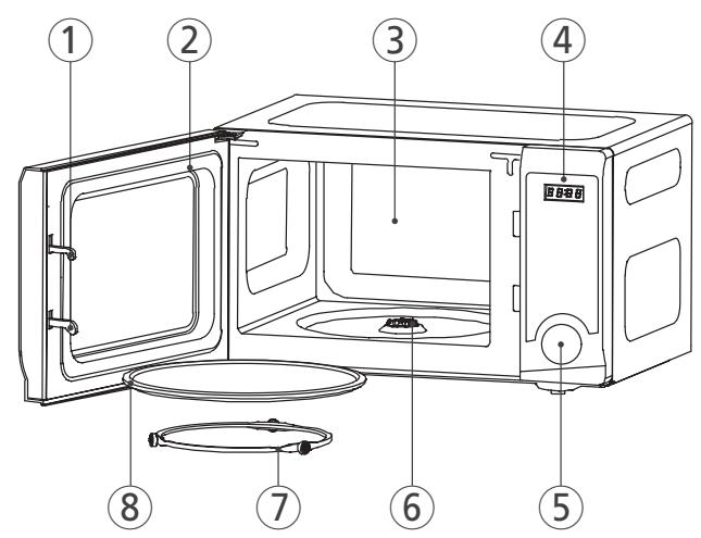
① Door latch - When the door is closed, it will automatically shut off. If the door is opened while the oven is operating, the magnetron will automatically shut off.
② Door seal - The door seal surfaces prevent microwaves escaping from the oven cavity.
③ Oven cavity
④ Control panel
⑤ Door open button - To open the door push the door open button.
(6) Coupler - This fits over the shaft in the center of the oven cavity floor. This is to remain in the oven for all cooking.
⑦ Roller guide - This must always be used for cooking together with the glass cooking tray.
Glass cooking tray - Made of special heat resistant glass. The tray must always be in proper position before operating. Do not cook food directly on the tray.
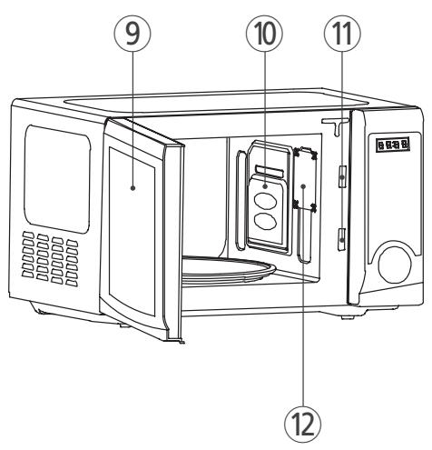
Viewing screen - Allows viewing of food. The screen is designed so that light can pass through, but not the microwave.
⑩ Waveguide cover - Protects the microwave outlet from splashes of cooking foods.
11 Safety interlock system
② Oven lamp - Automatically turns on during oven operating.
3. CONTROL PANEL
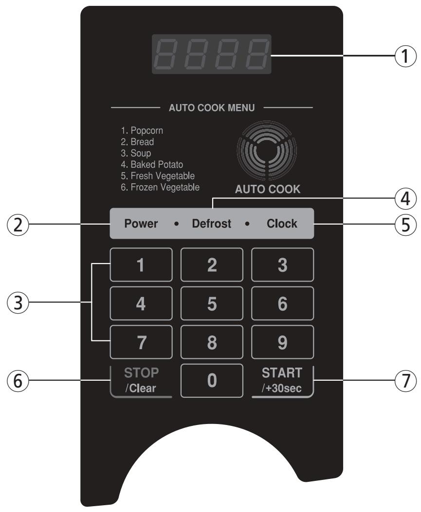
① DISPLAY - Cooking time, power level, indicators and current time are displayed.
② POWER - Used to set power level.
③ TIME SET PAD - Used to set the cooking time and the current time.
DEFROST - Used to defrost foods for weight and time.
⑤ CLOCK - Used to set clock.
⑥ STOP / CLEAR - Used to stop the oven operation or to delete the cooking data.
⑦ START / +30 SEC - Used to start the oven and also used to set a reheat time.
1. Steady, flat location.
This microwave oven should be set on a steady, flat surface.
2. Leave space behind and side.
All air vents should be kept clear. If all vents are covered during operation, the oven may be overheated and, eventually, cause oven failure.
3. Away from radio, and TV sets
Poor television reception and radio interference may result if the oven is located close to a TV, radio, antenna, or feeder and so on. Position the oven as far from them as possible.
4. Away from heating appliances and water taps
Keep the oven away from hot air, steam or splash when choosing a place to position it, or the insulation might be adversely affected and breakdowns occur.
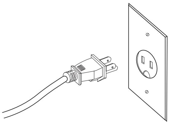
5. Power supply
- Check your local power source.
This microwave oven requires a current of approximately 14 amperes, 120Volts, 60Hz grounded outlet.
- A short power-supply cord is provided to reduce the risks resulting from becoming entangled in or tripping over a longer cord.
- Longer cord sets or extension cords are available and may be used if care is exercised in their use.
- If a long cord or extension cord is used:
1) The marked electrical rating of the cord set or extension cord should be at least as great as the electrical rating of the appliance.
2) The extension cord must be a grounding type 3-wire cord.
3) The longer cord should be arranged so that it will not drape over the counter top or tabletop where it can be pulled on by children or tripped over unintentionally.
6. Examine the oven after unpacking for any damage such as:
A misaligned door, broken door or a dent in cavity.
If any of the above are visible, DO NOT INSTALL, and notify dealer immediately.
- Connect the mains lead to an electrical outlet.
- After placing the food in a suitable container, open the oven door and put it on the glass tray. The glass tray must always be in place during cooking.
- Close the door securely.
- The oven door can be opened at any time during operation by pushing the door open button on the control panel. The oven will automatically shut off. To restart the oven, close the door and then touch the START pad.
- Each time a pad is touched, a BEEP will sound to acknowledge the touch.
- The oven automatically cooks on full power unless set to a lower power level.
- The display will show": 0" when the oven is plugged in.
- Time clock returns to the present time when the cooking time ends.
- When the STOP/CLEAR pad is touched during the oven operation, the oven stops cooking and all information retained.
To erase all information (except the present time), touch the STOP/CLEAR pad once more. If the oven door is opened during the oven operation, all information is retained.
- If the START pad is touched and the oven does not operate, check the area between the door and door seal for obstructions and make sure the door is closed securely. The oven will not start cooking under the door is completely closed or the program has been reset.
Make sure the oven is properly installed and plugged into the electrical outlet.
Wattage output chart
The power level is set by touching the Micro Power pad. The chart shows the display, the power level and the percent -age of power.
| Touch Power pad | Power level (Display) | Approximate Percentage of Power |
| once | P-HI | 100% |
| twice | P-90 | 90% |
| 3 times | P-80 | 80% |
| 4 times | P-70 | 70% |
| 5 times | P-60 | 60% |
| 6 times | P-50 | 50% |
| 7 times | P-40 | 40% |
| 8 times | P-30 | 30% |
| 9 times | P-20 | 20% |
| 10 times | P-10 | 10% |
| 11 times | P-00 | 0% |
Cautions to be observed when trouble shooting.
Unlike many other appliances, the microwave oven is high-voltage, high-current equipment. It is completely safe during normal operation. However, carelessness in servicing the oven can result in an electric shock or possible danger from a short circuit. You are asked to observe the following precautions carefully.
- Always remove the power plug from the outlet before servicing.
- Use an insulated screwdriver and wear rubber gloves when servicing the high voltage side.
- Discharge the high voltage capacitor before touching any oven components or wiring.
(1) Check the grounding.
Do not operate on a two-wire extension cord.
The microwave oven is designed to be used while grounded.
It is imperative, therefore, to make sure it is grounded properly before beginning repair work.
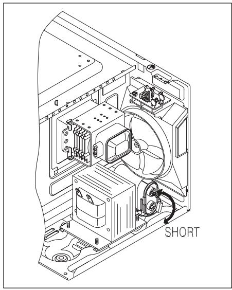
(2) Warning about the electric charge in the high voltage capacitor.
For about 30 seconds after the operation has stopped, electric charge remains in the high voltage capacitor.
When replacing or checking parts, short between oven chassis and the negative high terminal of the high voltage capacitor by using a properly insulated screwdriver to discharge.
- When the 12A fuse is blown due to the operation of the monitor switch; replace primary interlock switch, secondary interlock switch and interlock monitor switch.
- After repair or replacement of parts, make sure that the screws are properly tightened, and all electrical connections are tightened.
- Do not operate without cabinet.
CAUTION : Service personnel should remove their watches whenever working close to or replacing the magnetron.
WARNING : When servicing the appliance, take care when touching or replacing high potential parts because of electrical shock or exposing microwave. These parts are as follows - HV Transformer, Magnetron, HV Capacitor, HV Diode, HV Fuse.
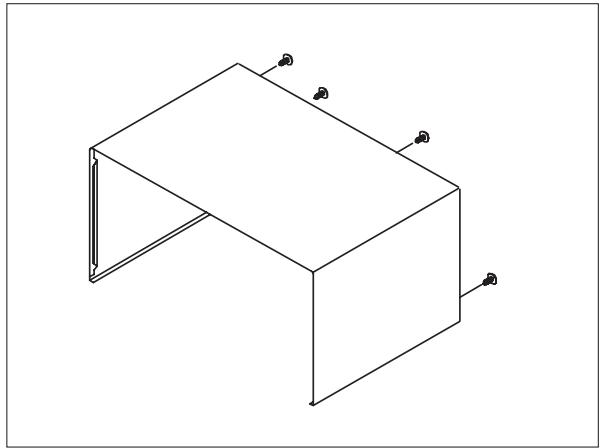
1. To remove cabinet
1) Remove three screws on cabinet back.
2) Push the cabinet backward.
2. To remove door assembly
1) Remove two screws which secure the stopper hinge top.
2) Remove the door assembly from top plate of cavity.
3) Reverse the above for reassembly.
NOTE : After replacing the door assembly, perform a check of correct alignment with the hinge and cavity front plate.
3. To remove door parts.
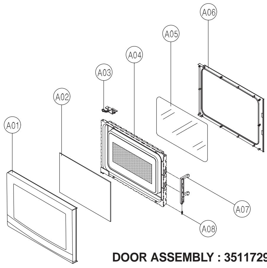
DOOR ASSEMBLY : 3511729900
| REF. NO | PART CODE | PART NAME | DESCRIPTION | Q'TY | REMARK |
| A01 | 3512211100 | FRAME DOOR | ABS SG-0760D, SG-175 | 1 | |
| A02 | 3517011010 | BARRIER-SCREEN*0 | TEMP GLASS T3.2 | 1 | |
| A03 | 3515204120 | STOPPER HINGE *T AS | KOR-6L0B1A | 1 | |
| A04 | 3511706130 | DOOR painting AS | KOR-6L0B1A | 1 | |
| A05 | 3517003700 | BARRIER-SCREEN *I | POLYESTER T0.1 | 1 | |
| A06 | 3512302700 | GASKET DOOR | PP | 1 | |
| A07 | 3513100700 | HOOK | POM | 1 | |
| A08 | 3515101300 | SPRING HOOKH | SW-3 | 1 |
(1) Remove the gasket door from the door painting as.
(2) Remove the barrier screen inner from the door painting as.
(3) Remove the frame door from the door painting as.
(4) Remove the stopper hinge top as from the door painting as.
(5) Remove the spring hook and the hook from the door painting as.
(6) Remove the barrier screen outer from the frame door.
(7) Reverse the above steps for reassembly.
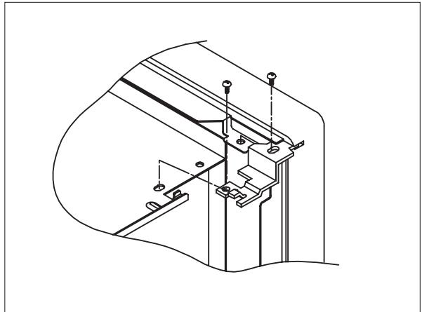
4. Method to reduce the gap between the door seal and the oven front surface.
(1) To reduce gap located on part 'A'
- Loosen two screws on the stopper hinge top, and then push the door to contact the door seal to the oven front surface.
- Tighten two screws.
(2) To reduce gap located on part 'B'
- Loosen two screws on the stopper hinge under, and then push the door to contact the door seal to the oven front surface.
- Tighten two screws.
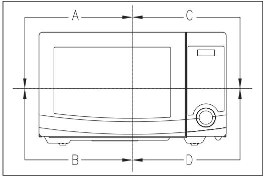
(3) To reduce gap located on part 'C'
- Loosen the screw on the interlock switch assembly located the top of the oven body.
- Draw the interlock switch assembly inward as possible to engage with the hook on the door bottom.
- Tighten a screw.
(4) To reduce gap located on part 'D'
- Loosen the screw on the interlock switch assembly located the bottom of the oven body.
NOTE :A small gap may be acceptable if the microwave leakage does not exceed 4mW/cm^2
5. To remove control panel parts.
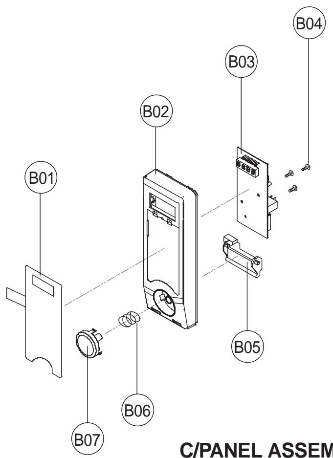
C/PANEL ASSEMBLY: PKCPSWFLPO
| REF. NO | PART CODE | PART NAME | DESCRIPTION | Q'TY | REMARK |
| B01 | 3518572860 | SWITCH MAMBRANE | KOR-6L3B1A | 1 | |
| B02 | 3516735010 | CONTROL-PANEL | ABS VT-0826 AF-348 | 1 | |
| B03 | PKMPMSFLA0 | PCB MAIN MANUAL AS | KOR-6L3B3A27(POPCORN) | 1 | |
| B04 | 7122401211 | SCREW TAPPING | T2S TRS 4X12 MFZN | 3 | |
| B05 | 3513702700 | LEVER DOOR OPEN | PP | 1 | |
| B06 | 441G430171 | SPRING BUTTON | SWP DIA. 0.7 | 1 | |
| B07 | 3516915700 | BUTTON DOOR OPEN | ABS SG-076D SG-175 | 1 |
(1) Remove the screw which secure the control panel, push up two snap fits and draw forward the control panel assembly.
(2) Remove three screws which secure the PCB assembly to control panel.
(3) Disconnect membrane tail from the connector of the PCB assembly.
(4) Remove the PCB from the control panel.
(5) Remove the membrane, lever door open, spring button and button door open from the control panel.
(6) Reverse the above steps for reassembly.
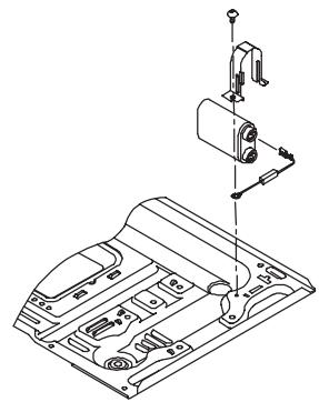
6. To remove high voltage capacitor.
1) Remove the screw which secure the grounding ring terminal of the H.V. diode and the capacitor holder.
2) Remove the H.V. diode from the capacitor holder.
3) Reverse the above steps for reassembly.
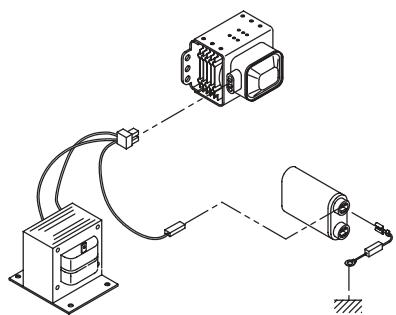
High voltage circuit wiring
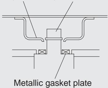
7. To remove magnetron.
1) Remove the screw which secure the magnetron.
2) Remove the magnetron.
3) Reverse the above steps for reassembly.
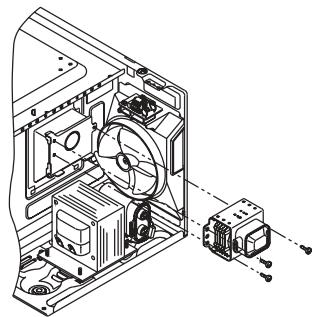
NOTE: Never install the magnetron without the metallic gasket plate which is packed with each magnetron to prevent microwave leakage. Whenever repair work is carried out on magnetron, check the microwave leakage. It shall not exceed 4mW/cm^2 for a fully assembled oven with door normally closed.
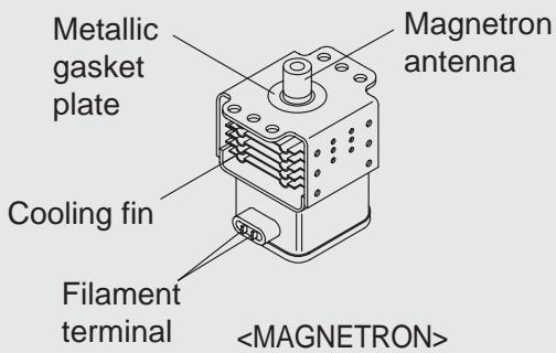
Wave guide Magnetron antenna
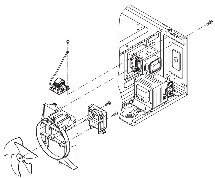
8. To remove wind guide assembly.
1) Remove the screw for earthing.
2) Remove the noise filter from the wind guide.
3) Remove the screw which secure the wind guide assembly.
4) Draw forward the wind guide assembly.
5) Pull the fan from the motor shaft.
6) Remove two screws which secure the motor shaded pole.
7) Remove the motor shaded pole.
8) Reverse the above steps for reassembly.
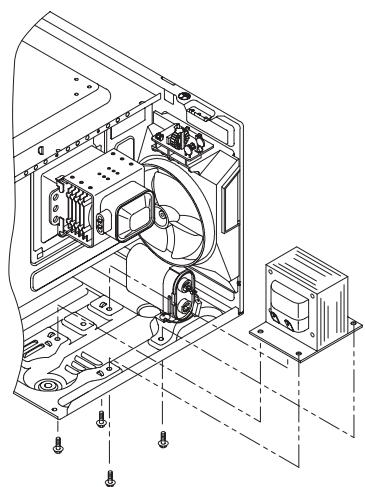
9. To remove H.V.transformer.
1) Remove four screws holding the H.V.transformer.
2) Remove the H.V.transformer.
3) Reverse the above steps for reassembly.
The door lock mechanism is a device which has been specially designed to completely eliminate microwave radiation when the door is opened during operation, and thus to perfectly prevent the danger resulting from the leakage of microwave.
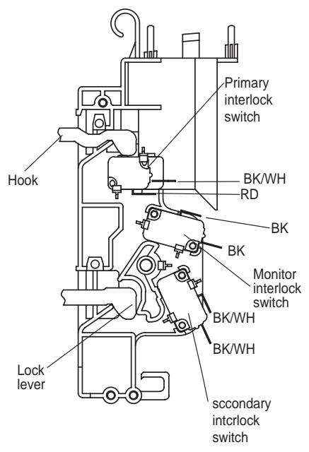
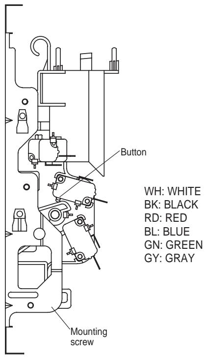
(1) Primary interlock switch
When the door is closed, the hook locks the oven door. If the door is not closed properly, the oven will not operate.
When the door is closed, the hook pushes the button of the microswitch. Then the button of the primary interlock switch brings it under "ON" condition.
(2) Secondary interlock switch and interlock monitor switch
When the door is closed, the hook pushes the lock lever downward. The lock lever presses the button of the interlock monitor switch to bring it under "OFF" condition and presses the button of the secondary interlock switch to bring it under "ON" condition.
ADJUSTMENT :
Interlock monitor switch
When the door is closed, the interlock monitor switch should be "OFF" condition before other switches are "ON" condition.
When the door is opened, the interlock monitor switch should be "ON" condition after other switches are "OFF" condition.
(3) Adjustment steps
a) Loosen the mounting screw.
b) Adjust interlock switch assembly position.
Actuation distance of primary and secondary interlock switch shall be adjusted almost 0mm.
c) Make sure that lock lever moves smoothly after adjustment is completed.
d) Tighten completely a mounting screw.
NOTE :
Microwave emission test should be performed after adjusting interlock mechanism. If the microwave emission exceeds 4mW/cm^2 , readjust interlock mechanism.
Following the procedure below to check if the oven is defective or not.
- Check grounding before trouble checking.
- Be careful of the high voltage circuit.
- Discharge the high voltage capacitor.
- When checking the continuity of the switches, fuse or high voltage transformer, disconnect one lead wire from these parts and check continuity with the AC plug removed. To do otherwise may result in a false reading or damage to your meter.
NOTE : When electric parts are checked, be sure the power cord is not inserted the wall outlet.
Check wire harness, wiring and connected of the terminals and power cord before check the parts listed below.
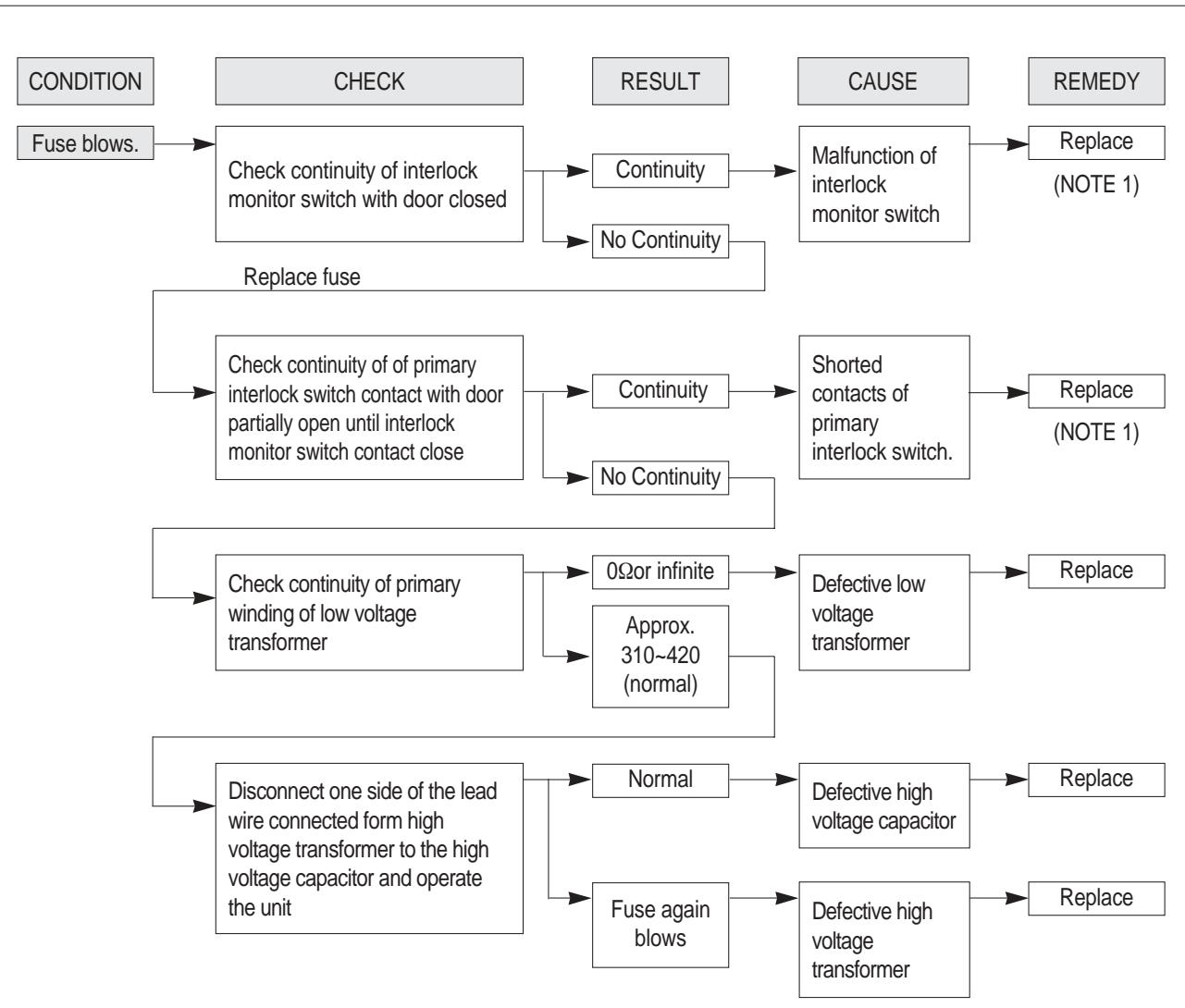
(TROUBLE 1) Oven does not operate at all; any inputs can not be accepted.
NOTE 1
All these switches must be replaced at the same time, please refer to "Interlock Mechanism And Adjustment".
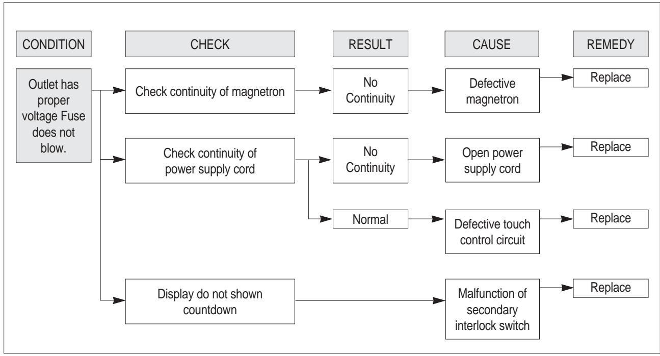
(TROUBLE 2) Display shows all figures selected, but oven does not start cooking, even though desired program and time are set and the START pad is touched.
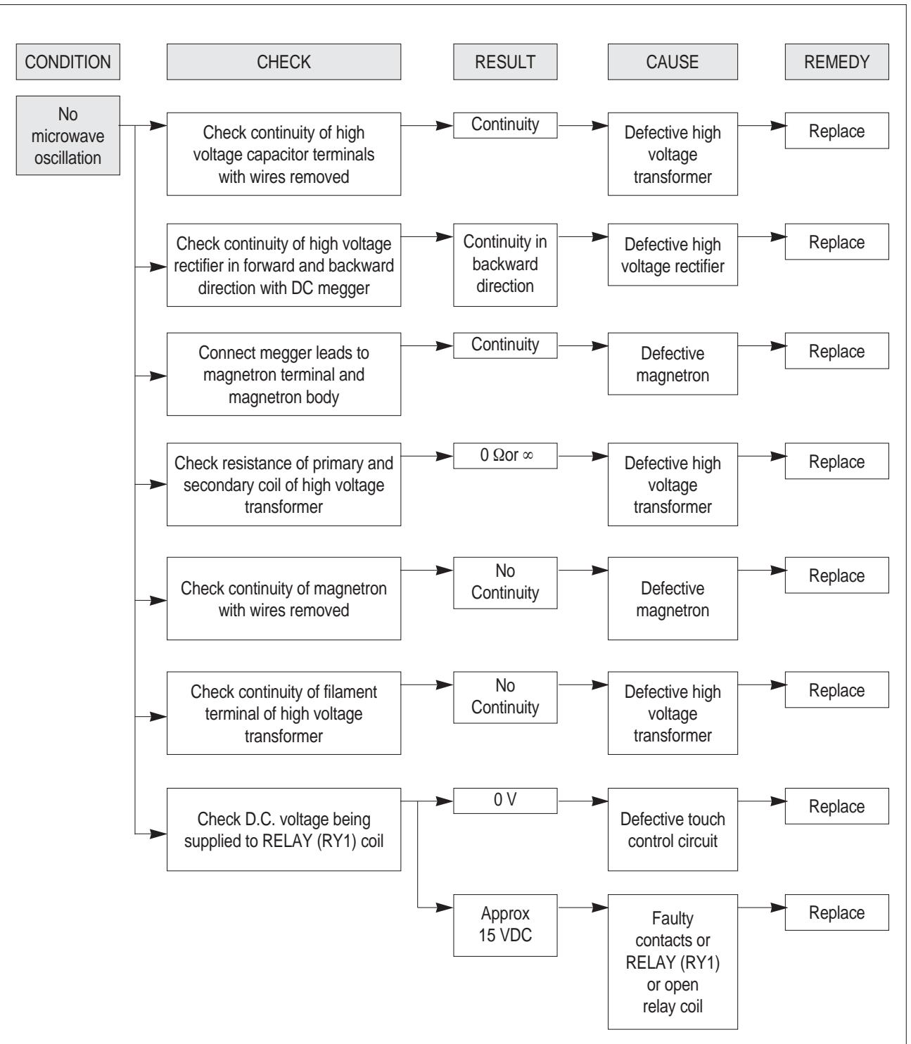
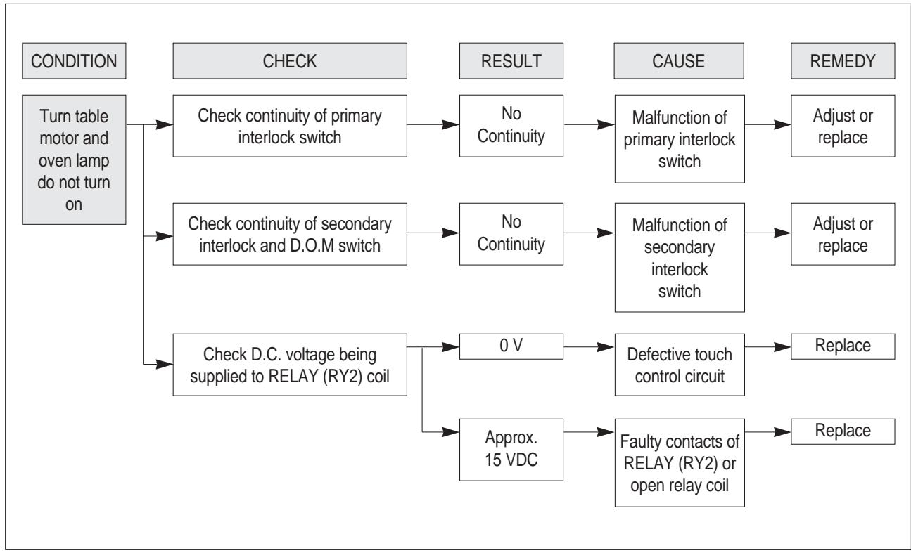
(TROUBLE 3) No microwave oscillation even though fan motor rotates.
(TROUBLE 4) The following visual conditions indicate a probable defective touch control circuit
- Incomplete segments,
1) Segments missing.
2) Partical segments missing.
3) Digit flickering other than normal display slight flickering.
4) " :0" does not display when power is on.
- A distinct change in the display are not on when they numbers is the display.
- One or more digits in the display are not on when they should be.
- Display indicates a number different from one touched.
- Specific numbers (for example 2 or 3) will not display when the panel is touched.
- Display does not count down or up with time cooking or clock operation.
- Oven is programmable and cooks normally but no display shows.
- Display obviously jumps in time while counting down.
- Display counts down noticeably too fast while cooking.
- Display does not show the time of day when the STOP/CLEAR button is pushed. (in case of setting the present time)
- Oven lamp and turntable motor do not stop although cooking is finished. Check if the RELAY 2 contacts close. If they close, replace P.C.B assembly.
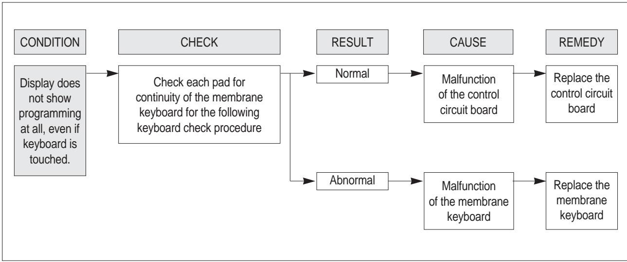
NOTE
Before following the particular steps listed above in the troubleshooting guide for the failure of membrane keyboard, please check for the continuity of each wire-harness between the membrane keyboard and P.C.B. assembly.
1. MEASUREMENT OF THE MICROWAVE POWER OUTPUT
Microwave output power can be checked by indirectly measuring the temperature rise of a certain amount of water exposed to the microwave as directed below.
PROCEDURE
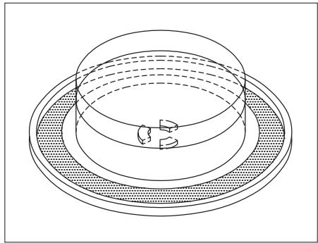
- Microwave power output measurement is made with the microwave oven supplied at rated voltage and operated at its maximum microwave power setting with a load of 1000 ± 5cc of potable water.
- The water is contained in a cylindrical borosilicate glass vessel having a maximum material thickness of 3mm and an outside diameter of approximately 190mm .
- The oven and the empty vessel are at ambient temperature prior to the start of the test.
The initial temperature of the water is 10± 2^ (50± 3.6^)
It is measured immediately before the water is added to the vessel.
After addition of the water to the vessel, the load is immediately placed on the center of the shelf, which is in the lowest normal position.
- Microwave power is switched on.
- Heating time should be exactly A seconds. (Refer to table as following)
Heating time is measured while the microwave generator is operating at full power.
The filament heat-up time for magnetron is not included.
- The initial and final temperature of water is selected so that the maximum difference between the ambient and final water temperature is 5K.
- The microwave power output P in watts is calculated from the following formula :
P=4187X△T/t
- T is difference between initial and ending temperature.
It is the heating time.
The power measured should be B (Refer to SPECIFICATIONS)W±10.0%.
CAUTION :
- Water load should be measured exactly to 1 liter.
- Input power voltage should be exactly specified voltage(Refer to SPECIFICATIONS).
- Ambient temperature should be 20 ± 2^ C ( 68 ± 3.6^ F )
Heating time for power output:
| A(second) | 70 | 64 | 60 | 56 | 52 | 49 | 47 | 44 | 42 | 40 | 38 |
| B(W) | 600 | 650 | 700 | 750 | 800 | 850 | 900 | 950 | 1000 | 1050 | 1100 |
- Make sure to check the microwave leakage before and after repair of adjustment.
- Always start measuring of an unknown field to assure safety for operating personnel from microwave energy.
- Do not place your hands into any suspected microwave radiation field unless the safe density level is known.
- Care should be taken not to place the eyes in direct line with the source of microwave energy.
- Slowly approach the unit under test until the radiometer reads an appreciable microwave leakage from the unit under the test.
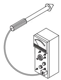
PROCEDURE
- Prepare Microwave Energy Survey Meter, 600cc glass beaker, and glass thermometer 100^(212^) .
- Pour 275cc± 15cc of tap water initially at 20± 5^(68± 9^) in the 600cc glass beaker with an inside diameter of approx. 95mm(3.5in.) .
- Place it at the center of the tray and set it in a cavity.
- Close the door and operate the oven.
- Measure the leakage by using Microwave Energy Survey Meter with dual ranges, set to 2450MHz.
1) Measured radiation leakage must not exceed the value prescribed below. Leakage for a fully assembled oven with door normally closed must be less than 4mW/cm^2 .
2) When measuring the leakage, always use the 5cm(2in.) space cone with probe. Hold the probe perpendicular to the cabinet and door. Place the space cone of the probe on the door, cabinet, door seem, door viewing screen, the exhaust air vents and the suction air vents.
3) Measuring should be in a counter-clockwise direction at a rate of 1 in./sec. If the leakage of the cabinet door seem is unknown, move the probe more slowly.
4) When measuring near a corner of the door, keep the probe perpendicular to the areas making sure the probe end at the base of the cone does not get closer than 2 in. from any metal. If it does not, erroneous reading may result.
3. COMPONENT TEST PROCEDURE
- High voltage is present at the high voltage terminal of the high voltage transformer during any cooking cycle.
- It is neither necessary nor advisable to attempt measurement of the high voltage.
- Before touching any oven components or wiring, always unplug the oven from its power source and discharge the capacitor.
1. High voltage transformer
(1) Remove connections from the transformer terminals and check continuity.
(2) Normal readings should be as follows:
Secondary winding........................Approx. 110 ± 10%
Filament winding........................Approx. 0
Primary winding.. Approx. 19
2. High voltage capacitor
(1) Check continuity of capacitor with meter on the highest OHM scale.
(2) A normal capacitor will show continuity for a short time, and then indicate 10MΩonce the capacitor is charged.
(3) A shorted capacitor will show continuous continuity.
(4) An open capacitor will show constant 10M
(5) Resistance between each terminal and chassis should be infinite.
3. High voltage diode
(1) Isolate the diode from the circuit by disconnecting the leads.
(2) With the ohmmeter set on the highest resistance scale measure the resistance across the diode terminals.
Reverse the meter leads and again observe the resistance reading.
Meter with 6V, 9V or higher voltage batteries should be used to check the front-back resistance of the diode, otherwise an infinite resistance may be read in both directions.
A normal diode's resistance will be infinite in one direction and several hundred KΩin the other direction.
4. Magnetron
For complete magnetron diagnosis, refer to "Measurement of the Microwave Power Output".
Continuity checks can only indicate and open filament or a shorted magnetron.
To diagnose for an open filament or a shorted magnetron.
(1) Isolate magnetron from the circuit by disconnecting the leads.
(2) A continuity check across magnetron filament terminals should indicate 0.1 or less.
(3) A continuity check between each filament terminal and magnetron case should read open.
5. Fuse
If the fuse in the primary and monitor switch circuit is blown when the door is opened, check the primary and monitor switch before replacing the blown fuse.
In case the fuse is blown by an improper switch operation, replace the defective switch and fuse at the same time.
Replace just the fuse if the switches operate normally.
1. CIRCUIT CHECK PROCEDURE
1. Low voltage transformer check
The low voltage transformer is located on the P.C.B.
Measuring condition: Input voltage: 230V/Frequency : 50Hz
| Terminal Voltage | LOAD | NO LOAD |
| (4,5)-6 or (7, 8)-6 | AC 14 V | AC 17 V |
NOTE
- Refer to Circuit Diagram.
- Secondary side voltage of the low voltage transformer changes in proportion to fluctuation of power source voltage.
- The allowable tolerance of the secondary voltage is within ± 5% of nominal voltage.
2. Voltage Check
- Key check point
| NO | CHECK POINT | REMARK |
| 1 | IC 1 PIN 5 | 5 VDC |
| 2 | IIC 1 PIN 8 | 5V 0V T T:20ms(50Hz) |
| 3 | IC 1 PIN 19 OR PIN 20 | 5V 0V T T:250ns(4MHz) |
- Check method
| NO | MEASURE POINT | WAVE FORM | REMEDY | REMARK |
| 1 | MP1 | DC 5V ±0.25V | Replace Q8, R28, ZD3, C2, EC1 | NO LOAD |
| 2 | MP2 | DC 15V ±3.0V | Replace EC3, D11, D12, D13, C9 | NO LOAD |
NOTE
Each measure point must be measured with GND points.
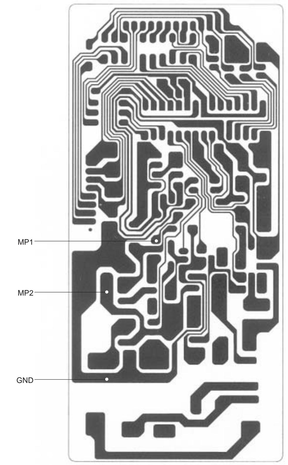
Measure Point
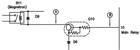
3. When there is no microwave oscillation
1) When touching START pad, oven lamp does not turn on.
Fan motor does not rotate, but cook indicator in display comes on.
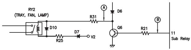
- Check method
| STATE\POINT | A | B |
| RELAY 2 ON | 5V DC | GND |
| RELAY 2 OFF | GND | 15V DC |
2) When touching START pad, oven lamp turns on.
Fan motor and turntable rotate and cook indicator in display comes on.
- Check method
| STATE\POINT | A | B |
| RELAY 1 ON | 5V DC | GND |
| RELAY 1 OFF | GND | 15V DC |
- When the door is opened during operation, the count down timer does not stop.
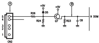
- Check method
| STATE\POINT | A | B |
| 1)DOOR OPEN | OPEN | 5VDC |
| 2)DOOR CLOSED | CLOSE | GND |
| CHECK NO | METHOD | REMEDY |
| 1 | Check the stage(ON, OFF) of the door open monitor switch by resistance measurement. | Replace door open monitor switch. |
- When the digital clock does not operate properly.
refer to Circuit Diagram
| POINT | WAVE FORM |
| IC 1 PIN 8 | 5V 0V T T:16.67ms(60Hz) |
*If clock does not keep exact time, you must check resistor R12, R17, D8, C3 and zener diode ZD1.
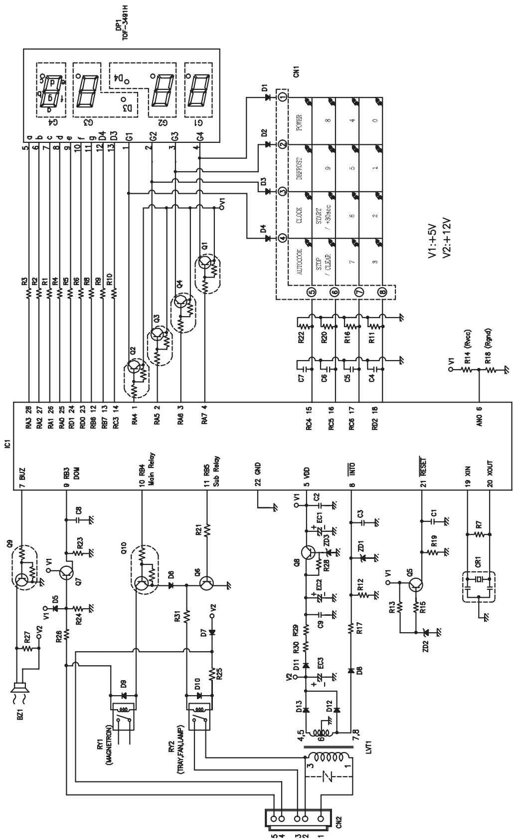
2. PCB CIRCUIT DIAGRAM
3. PCB LOCATION NO.
| NO | NAME | SYMBOL | SPECIFICATION | PART CODE | Q'TY |
| 1 | BUZZER | BZ1 | BM-20K | 3515600100 | 1 |
| 2 | CAPACITOR CERAMIC | C1,2,3,8,9 | 50V 0.1UF Z AXIAL | CCZF1H104Z | 5 |
| 3 | CAPACITOR CERAMIC | C4,5,6,7 | 50V 1000PF Z AXIAL | CCZB1H102K | 4 |
| 4 | CAPACITOR ELECTRO | EC1 | 50V RS 10UF(5X11) | CEXE1H100A | 1 |
| 5 | CAPACITOR ELECTRO | EC2 | 50V RSS 220UF(10X16) | CEXF1H221V | 1 |
| 6 | CAPACITOR ELECTRO | EC3 | 25V RSS 1000UF(13X20) | CEXF1E102V | 1 |
| 7 | CONNECTOR WAFER | CN1 | FCZ254-8 | 441M367130 | 1 |
| 8 | CONNECTOR WAFER | CN2 | YW396-725V | 3519150550 | 1 |
| 9 | DIODE SWITCHING | D1~10 | 1N4148 | DZN4148--- | 10 |
| 10 | DIODE RECTIFYING | D11~13 | 1N4004A AUTO 52MM | DZN4004A-- | 3 |
| 11 | DIODE ZENER | ZD1 | UZ -5.1BSB | DZUZ5R1BSB | 1 |
| 12 | DIODE ZENER | ZD2 | UZ -3.3BSB | DZUZ3R3BSB | 1 |
| 13 | DIODE ZENER | ZD3 | UZ -5.6BSB | DZUZ5R6BSB | 1 |
| 14 | FOAM | - | CR 8TX35X10 | 3517307000 | 1 |
| 15 | LED DISPLAY | DP1 | TOF-3491HG-B | DTOF3491HG | 1 |
| 16 | IC MICOM | IC1 | HMS81C1408B-HN079 | 150SR6L0B2 | 1 |
| 17 | PCB MAIN | M325 | 65X139 | 3514330740 | 1 |
| 18 | RESISTOR | R13 | 1/6W 200 OHM 5% | RD-AZ201J- | 1 |
| 19 | RESISTOR | R1~6,8~10 | 1/6W 330 OHM 5% | RD-AZ331J- | 9 |
| 20 | RESISTOR | R15,27,28 | 1/6W 1K OHM 5% | RD-AZ102J- | 3 |
| 21 | RESISTOR | R21,26 | 1/6W 4.7K OHM 5% | RD-AZ472J- | 2 |
| 22 | RESISTOR | R12,17,19,23 | 1/6W 10K OHM 5% | RD-AZ103J- | 4 |
| 23 | RESISTOR | R24 | 1/6W 47K OHM 5% | RD-AZ473J- | 1 |
| 24 | RESISTOR | R11,16,20,22 | 1/6W 100K OHM 5% | RD-AZ104J- | 4 |
| 25 | RESISTOR | R7 | 1/6W 1M OHM 5% | RD-AZ105J- | 1 |
| 26 | RESISTOR | R25 | 1/4W 51 OHM 5% | RD-4Z510J- | 1 |
| 27 | RESISTOR | R31 | 1/4W 100 OHM 5% | RD-4Z101J- | 1 |
| 28 | RESISTOR | R29,30 | 1/2W 27 OHM 5% | RD-2Z270JS | 2 |
| 29 | RESONATOR CERAMIC | CR1 | CRT-4.00MS | 5P4R00MTS- | 1 |
| 30 | SW RELAY | RY1 | G5G-1A-DT DC 12V | 5SC0101123 | 1 |
| 31 | SW RELAY | RY2 | CS11-12SH | 5SC0101128 | 1 |
| 32 | TRANSistor | Q5,7 | KTA1266Y AUTO | TZTA1266Y- | 2 |
| 33 | TRANSistor | Q6,8 | KTC3198GR AUTO | TZTC3198GR | 2 |
| 34 | TRANSistor | Q1~4 | KRA106M AUTO | TZRA106M-- | 4 |
| 35 | TRANSistor | Q9,10 | KRC106M AUTO | TZRC106M-- | 2 |
| 36 | TRANS POWER | LVT1 | DMR-63KP | 5EPU035305 | 1 |
| 37 | WIRE COPPER 7.5MM | J1,2,4,5,7,8 | 1/0.52 TIN COATING | 85801052GY | 6 |
| 38 | WIRE COPPER 10MM | J3,6, | 1/0.52 TIN COATING | 85801052GY | 2 |
| 39 | RESISTOR | R14 (Rvcc) | 1/6W 5.1K OHM 5% | RD-AZ512J- | 1 |
| 40 | RESISTOR | R18 (Rgnd) | 1/6W 3.3K OHM 5% | RD-AZ332J- | 1 |
- DOOR ASSEMBLY
Refer to Disassembly and assembly. - CONTROL PANEL ASSEMBLY
Refer to Disassembly and assembly. - TOTAL ASSEMBLY
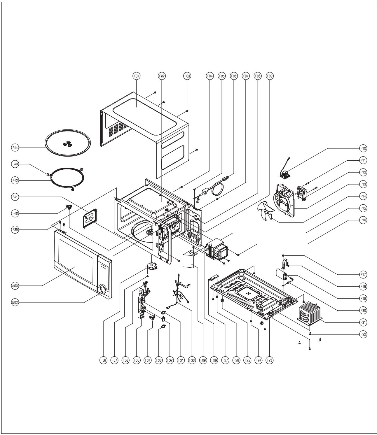
| REF. NO | PART CODE | PART NAME | DESCRIPTION | Q'TY |
| A00 | 3511729900 | DOOR AS | KQG-6L353S | 1 |
| B00 | PKCPSWFLP0 | CONTROL-PANEL AS | KOR-6L3B3A27 | 1 |
| F01 | 3510808410 | CABINET AS | KOR-6L0B1A | 1 |
| F02 | 3516117410 | CAIVITY AS | KOR-6L0B1A | 1 |
| F03 | 3516004100 | SPECIAL SCREW | T1 TRS LR4 POLE 4X10 MFZN | 4 |
| F04 | 7122401211 | SCREW TAPPING | T2S TRS 4X12 MFZN | 1 |
| F05 | 7S312X40A1 | SCREW TAPPING | T1 TRS 4*10 MFZN | 1 |
| F06 | 35113TEW55 | CORD POWER AS | 3X16AWG 70X70 100-RTML | 1 |
| F07 | 3516004100 | SPECIAL SCREW | T1 TRS LR4 POLE 4X10 MFZN | 1 |
| F08 | 7121300611 | SCREW TAPPING | T2S PAN 3X6 MFZN | 2 |
| F09 | 3518903400 | THERMOSTAT | OFF:150 ON:60 V187 | 1 |
| F10 | 3518608320 | NOISE-FILTER | DWLF-M12 D | 1 |
| F11 | 7121402511 | SCREW TAPPING | T2S PAN 4X25 MFZN | 2 |
| F12 | 3963822730 | MOTOR SHADED POLE | 120V 60HZ MW10XA-M02 | 1 |
| F13 | 3512527600 | GUIDE WIND | PP | 1 |
| F14 | 3511800300 | FAN | PP+30%GLASS | 1 |
| F15 | 3518004300 | MAGNETRON | RM228HFD 4CF | 1 |
| F16 | 7272400811 | SCREW TAPTITE | TT3 TRS 4X8 MFZN | 3 |
| F17 | 7S432X4081 | SPECIAL SCREW | TT3 TRS 4X8 SE MFZN | 1 |
| F18 | 3513003200 | HOLDER HV CAPACITOR | SECC T0.6 | 1 |
| F19 | 3518301301 | CAPACITOR HV | 2100VAC 0.70UF #187 | 1 |
| F20 | 3518400900 | DIODE HV AS | HVR-1X-30B #187 | 1 |
| F21 | 3518122930 | TRANS HV | DYAR60A0-63T A | 1 |
| F22 | 3516003700 | SPECIAL SCREW | TT3 HEX 4X8 FLG MFZN | 4 |
| F23 | 3510317500 | BASE | SBHG T0.5 | 1 |
| F24 | 7S312X40A1 | SCREW TAPPING | T1 TRS 4*10 MFZN | 5 |
| F25 | 3512100900 | FOOT | PP DASF-130 | 2 |
| F26 | 7S432X4081 | SPECIAL SCREW | TT3 TRS 4X8 SE MFZN | 1 |
| F27 | 3515201101 | STOPPER HINGE *U | SCP-1 T2.5 | 1 |
| F28 | 7S312X40A1 | SCREW TAPPING | T1 TRS 4*10 MFZN | 1 |
| F29 | 3512527800 | GUIDE AIR | SECC T0.5 | 1 |
| F30 | 3512720210 | HARNESS MAIN | KOR-6L0B1A | 1 |
| F31 | 4415A17352 | SW MICRO | VP-533A-OF SPNO #187 200G | 1 |
| F32 | 4415A66600 | SW MICRO | VP-532A-OF SPNC #187 200G | 1 |
| F33 | 3518571000 | SWITCH PUSH | MP101C | 1 |
| F34 | 3513702620 | LEVER LOCK | POM | 1 |
| F35 | 3513818900 | LOCK | PP FH44D GP-3152F | 1 |
| F36 | 3513601500 | LAMP | BL 125V 25W T25 C5A H187 | 1 |
| F37 | 7S312X40A1 | SCREW TAPPING | T1 TRS 4*10 MFZN | 1 |
| F38 | 3966821600 | MOTOR SYNCRO | 120V 60HZ ST-16 KX63MQAD A | 1 |
| F39 | 7272400811 | SCREW TAPTITE | TT3 TRS 4X8 MFZN | 2 |
| F40 | 3517400600 | COUPLER | XAREC | 1 |
| F41 | 3511406220 | COVER WAVE GUIDE | PP J640A WHITE | 1 |
| F42 | 3512517300 | GUIDE ROLLER | PP 5113MF6 A353B | 1 |
| F43 | 3514700710 | ROLLER | TEFLON | 3 |
| F44 | 3517203600 | TRAY | GLASS | 1 |

DAE\VOO
ELECTRONICS
S/M NO.:
DAEWOO ELECTRONICS CORP.
1-2, Jeo-dong 1(il)-ga, Jung-gu, Seoul, Korea
C.P.O. BOX 8003 SEOUL, KOREA
TELEX:DWELEC K28177-8
CABLE: "DAEWOOELEC"
PRINTED DATE: May. 2010