
T2130-9 - Printer TALLY - Free user manual and instructions
Find the device manual for free T2130-9 TALLY in PDF.
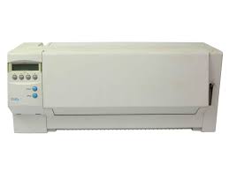
| Product type | 9-pin dot matrix printer |
| Brand | TALLY |
| Model | T2130-9 |
| Dimensions (W x D x H) | 485 x 206 x 245 mm (narrow version) |
| Weight | 9 kg (narrow version) |
| Power supply | AC 230 V ±10%, 50 Hz ±3% (Europe) |
| Power consumption | Max. 60 VA during operation, < 10 VA at rest |
| Print method | Serial with 9-pin dot matrix head, bidirectional |
| Print speed | 360 cps in HS-Draft/Draft Copy, 270 cps in Draft, 65 cps in NLQ/LQ (at 10 cpi) |
| Character densities | 5, 6, 7.5, 8.6, 10, 12, 15, 17.1, 20 cpi |
| Graphic density | 240 dpi horizontal, 144 dpi vertical |
| Interface | Parallel connector (Centronics) for transmission cable |
| Paper tray capacity | Approximately 30 sheets (63 g/m² paper, rear ejection) |
| Supported paper types | Single-sheet paper (60-120 g/m², width 76-220 mm) and continuous paper (60-120 g/m², width 76-254 mm) |
| Number of copies | 1 original + 5 copies (continuous multi-part paper) |
| Ribbon life | 4 million characters |
| Noise level | Approximately 55 dB(A) |
| Operating conditions | Temperature 10°C to 40°C, humidity 20% to 80% |
| Certifications | UL 1950, VDE-GS, CE, FCC Class B, UL/ULc |
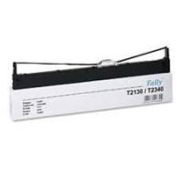
| Maintenance | Replacement of ink ribbon cartridge (ref. 044 829 for narrow version); exterior cleaning with a soft cloth |
| Safety | Do not open the cover without turning off the printer; unplug before servicing; have repairs carried out by qualified personnel |
| Included accessories | Power cable, quick start guide, CD-ROM with online documentation |
| Provided documents | User manual (124 pages), online documentation on CD-ROM (PDF format) |
Frequently Asked Questions - T2130-9 TALLY
User questions about T2130-9 TALLY
0 question about this device. Answer the ones you know or ask your own.
Ask a new question about this device
Download the instructions for your Printer in PDF format for free! Find your manual T2130-9 - TALLY and take your electronic device back in hand. On this page are published all the documents necessary for the use of your device. T2130-9 by TALLY.
USER MANUAL T2130-9 TALLY
This equipment generates and uses radio frequency energy and if not installed and used properly, that is, in accordance with the manufacturer's instructions, may cause interference in radio and television reception. It has been type tested and found to comply with the limits for class B computing devices in accordance with the specification in subpart J of part 15 of FCC rules, which are designed to provide reasonable protection against such interference in a residential installation. However, there is no guarantee that interference will not occur in a partial installation. If this equipment does cause interference to radio or television reception, which can be determined by turning the equipment off and on, the user is encouraged to try to correct the interference by one or more of the following measures:
Reorient the receiving antenna,
Relocate the peripheral away from the receiver,
Move the peripheral away from the receiver
Plug the peripheral into a different outlet, so that the peripheral and receiver are on different branch circuits
If necessary, the user should consult the dealer or an experienced radio/television technician for additional suggestions. The user may find the following booklet, prepared by the Federal Communications Commission, helpful: "How to Identify and Resolve Radio-TV Interference Problems".
This booklet is available from the U.S. Government Printing Office, Washington DC 20402 Stock No. 004.000.00345.4.
WARNING: To comply with FCC regulations on electromagnetic interference for a class B computing device, the printer cable must be shielded. To assure compliance with FCC regulations for a computing device, use a shielded interface cable with a metal shell connector. The use of cables not properly shielded may result in violating FCC regulations.
This digital apparatus does not exceed the class B limits for radio noise emissions from digital apparatus as set out in the radio interference regulations of the Canadian department of communications.
This unit complies with DOC standard C108.8-M 1983
The paper used is made of raw materials treated with a chlorine-free bleaching process.
CE This device fulfils the European standards requirements by complying with the Directive of the Commission dated May 3, 1989 (89/336/EEC) relating to electromagnetic compatibility and the Directive dated February 19, 1973 (73/23/EEC) relating to low-voltage electrical equipment. Conformity with the above mentioned Directives is indicated by the CE symbol attached to the device.
Note: Conformity may be affected by:
using interface cables not complying with the specifications
■ non-observation of important instructions in the operator's manual
■ installing components not approved for this device by the manufacturer
■ unauthorized manipulation
WARNING Only trained and qualified personnel may open covers or remove parts that are not explicitly shown and described in the User Guide as being accessible to the operator.
The printer at a glance 3
Installation 5
Unpacking the printer 5
Positioning your printer 5
Connecting the printer 6
Switching the printer on and off 6
Control panel 7
Online mode 7
Offline mode 7
Setup mode 7
Installing the ribbon cassette 8
Loading paper 10
Cut Sheet paper 10
Printer in fanfold paper mode 12
Changing the paper type 14
Paper path quick selection 14
Paper transport 15
Using 15
Moving paper to the tear position 15
Settings (I) 16
Setting the tear position 16
Setting the first printing line (TOF) 16
Settings (II) 18
Setting the print head gap 18
Changing paper in Setup mode 19
From fanfold paper to single sheet mode 19
From single sheet to fanfold paper mode 20
Selecting a font 21
Setting the character pitch 22
Specifications 23
Printer specifications 23
Paper specifications 23
Accessories 24
Introduction

Symbols used in this manual
This Operator's Manual is intended as a quick introduction into working with the printer and is to enable also unexperienced users to handle the device properly. It describes the most important functions of the printer and contains the essential information for your everyday work with the printer. A more detailed description of the printer, its characteristic features and further information is contained in the reference manual on the online CD-ROM which is included at the back of this manual.
Important information is highlighted in this manual by two symbols.
CAUTION marks information which must be observed in order to prevent injuries to the user and damage to the printer.
NOTE marks general or additional information about a specific topic
Important safety instructions
Read the following instructions carefully before putting the printer into operation in order to protect yourself from injury and avoid damage to the printer.
- Keep this Operator's Manual always readily accessible.
Place the printer on a stable surface so that it cannot fall down to the ground.
Avoid exposing the printer to high temperature or direct sunlight. - Keep all liquids away from the printer.
Do not expose the printer to shock, impact or vibration.
Never switch on the printer when it is not set to the correct voltage.

Never try to carry out maintenance and repair work yourself; always call a qualified service technician.

When you want to disconnect the printer from the mains power supply, always pull out the mains plug from the wall outlet.

You will find additional safety information at specific places in the text.
Using the online documentation
First install the Adobe Acrobat Reader on your hard disk unless the program has already been installed. To install it, follow the steps described in the README file in the READER directory. To start the online documentation, call the File Manager (Windows 3.1) or Explorer (Windows 95/Windows 98/Windows NT) and double click on the START.PDF file. Then follow the instructions and menus on the screen.
If your CD-ROM should be defective or missing, please consult your dealer.
The online documentation is also available as a printed manual (for a small fee) and via the internet.
Minimum hardware requirements: PC AT 486, 4 x CD-ROM, 15" monitor, mouse.
Troubleshooting
The online documentation supplied on the CD-ROM contains detailed information on troubleshooting.
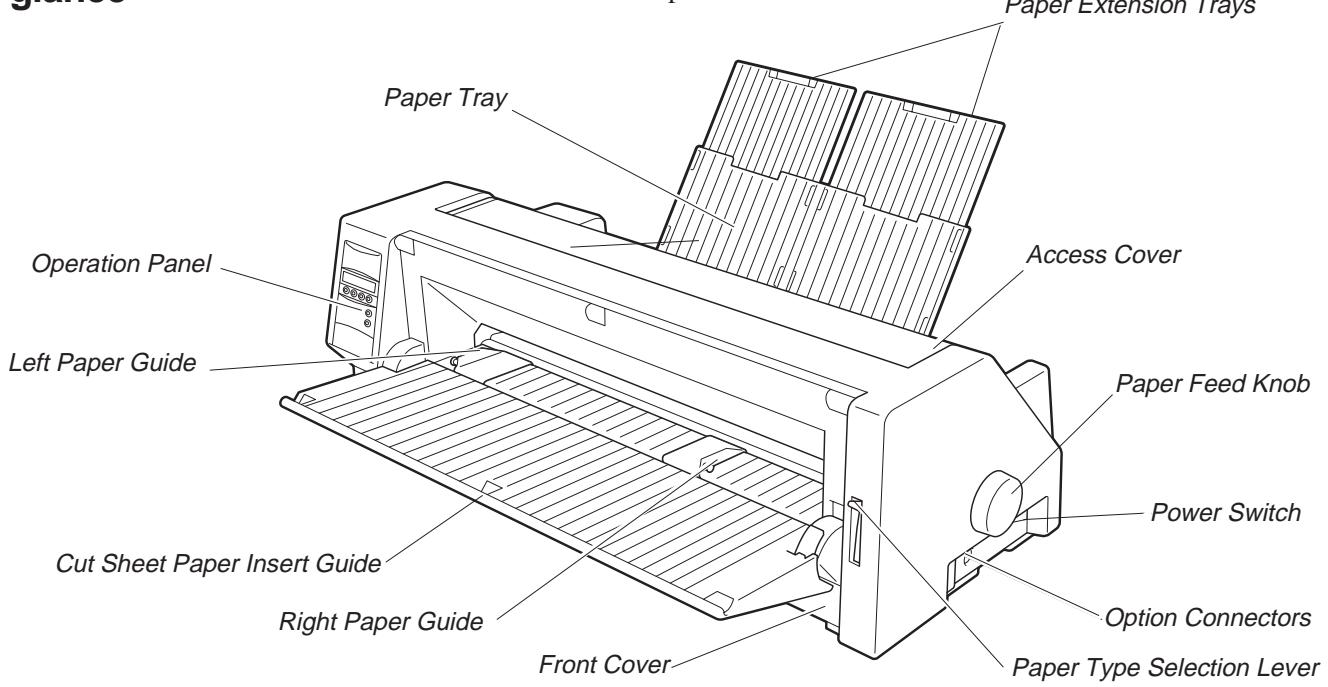
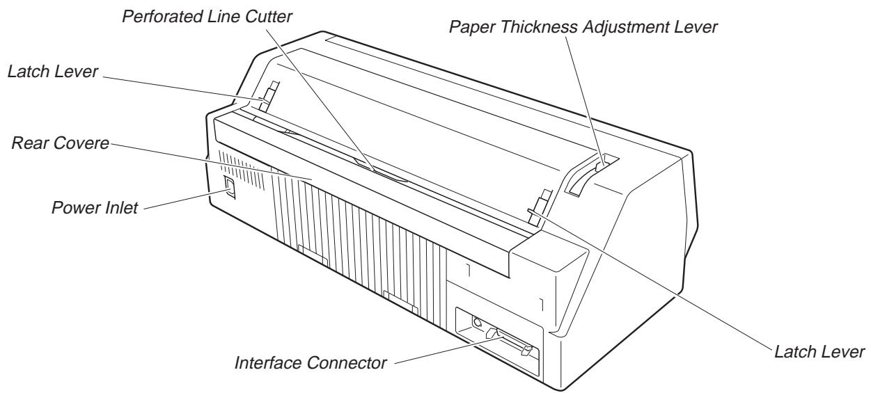
The printer at a glance
The following figures show the name of each printer part, and the table on the following page shows the functions of each part.
| Name | Functions |
| Operation Panel | It indicates the printer status, and is used to change various settings. |
| Paper Tray | It is used as a paper support for cut sheet paper already printed when the option “F-Eject” is set to OFF in the Initial Setting. |
| Paper Extension Trays | They are used for extending of the Paper Tray. |
| Access Cover | When the Ink-ribbon Cartridge is to be replaced or paper jams are to be removed, this cover is detached to allow access to the related parts. It also serves to protect operators from the mechanical movements of the printer. |
| Paper Feed Knob | It is used to manually feed paper forward or backward. |
| Power Switch | It is used to turn ON or OFF the power of the printer. |
| Option Connector | It is used to connect an Auto Sheet Feeder (ASF) or the Optional 2nd Tractor. |
| Paper Type Selection Lever | It is used to select the appropriate type of paper to be used in the printer: Cut Sheet Paper (upper position) Continuous Form Feed Paper (lower position) |
| Front Cover | It is opened when Continuous Form Feed Paper is to be set. This cover is detached when an Auto Sheet Feeder (ASF) or the Optional 2nd Tractor is to be attached. |
| Right Paper Guide | By aligning the right edge of the Cut Sheet Paper to this guide, an uneven feed can be prevented. |
| Cut Sheet Paper Insert Guide | It is opened for inserting Cut Sheet Paper and is used as a paper support. It is also used as a support for post-print Cut Sheet Paper when the option “F-Eject” is set to ASF, Single or ALL in the Initial Setting. |
| Left Paper Guide | It is used to adjust the left margin of the Cut Sheet Paper. |
| Latch Lever | By pulling this lever to the front, the latch is released and the Access Cover can be opened. |
| Perforated Line Cutter | Continuous Form Feed Paper will be cut at this position. By pressing the Tear key after printing, paper feeds up to this position. |
| Paper Thickness Adjustment Lever | It is used to adjust the paper-pinching strength of the printer in accordance with the thickness of the paper to be used. As for the adjustment ranges, see Paper Thickness Adjustment, page 18. |
| Interface Connector | It is used to connect the I/O cable to the system unit. |
| Power Inlet | It connects to the power cord. |
| Rear Cover | It is used to reduce noise. It must be removed when the paper tray is in upright position. |
Installation
Unpacking the printer Please open the printer package and check that all the following items are included.
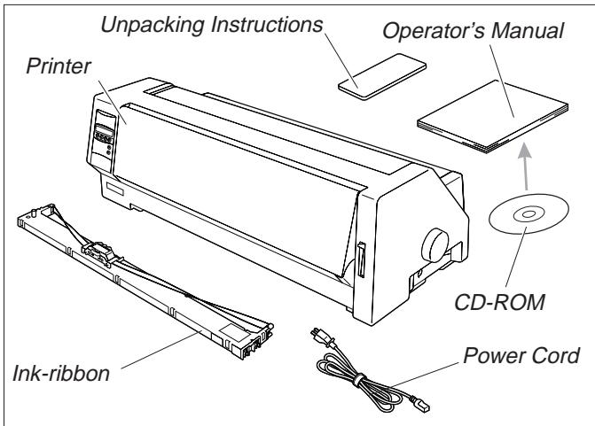
If any item is missing or damaged, please contact the store where the product was purchased.
Remove the transport protection elements as described in the unpacking instructions.
The carton and the packing materials will be necessary for moving or transporting the printer. Please store them in a safe place.
Positioning your printer
Place the printer on a stable, flat and non-slip surface in such a way that it cannot fall down. Ensure easy access to the control panel and the paper feeders and leave sufficient space for the paper ejected.
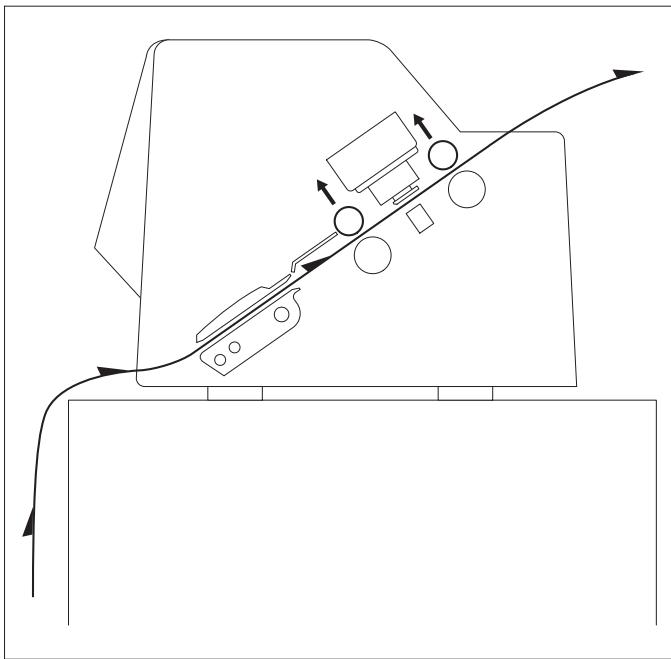
If frequent forward and return feed movements will be performed with fanfold paper, you should position the printer as illustrated in the figure.
When choosing a suitable place for your printer, you should also observe the following:

Never place the printer near sources of easily inflammable gas or explosive substances.
- Avoid exposing the printer to direct sunlight. If you cannot avoid placing the unit near a window, protect it from sunlight with a curtain.
Position the printer near the computer to which it will be connected. The distance must not exceed 2m
■ Ensure sufficient distance from radiators.
■ Ensure that the printer is not exposed to extreme variations in temperature or air humidity. Avoid exposure to dust.
Connecting the printer
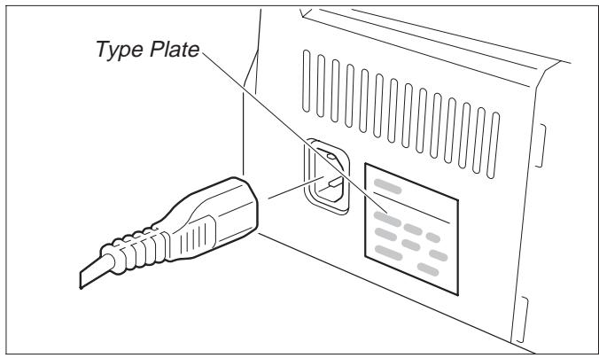
Make sure that the unit is set to the correct voltage (i.e. 230V for Europe, 120V for the USA). Refer to the type plate beside the power inlet on the rear side of the printer.
If this is not the case, contact your dealer.

Never switch on the printer when it is not set to the correct voltage since this could cause severe damage.
Connect the power cable to the printer's power inlet as shown in the figure.
Connect the power cable plug to a wall outlet.

Make sure that the printer and the computer are switched off.
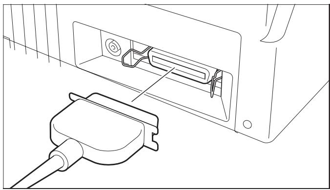
Connect the printer-end connector of the data cable to the female interface connector and secure it with the spring clips.
Connect the other end of the cable to the computer.
> Switching the printer on and off
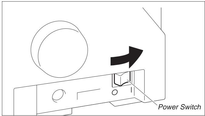
The power switch, which is used for switching the printer on and off, is located at the right side of the printer.
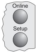
Control panel

You can control printer operation using the control panel and the keys.
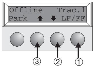
The first line of the display informs you about whether the printer is in Online or in Offline mode and about the paper path selected (Trac.1 or Single).
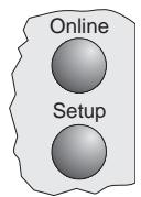
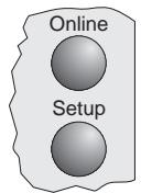
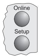
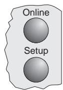
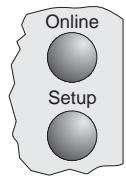
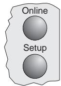
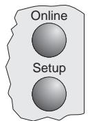
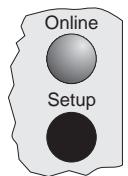
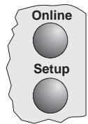
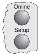
> Online mode
When switching on the printer, it automatically selects Online mode. It can receive data from the computer only in this mode.

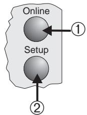
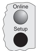
① Sets the printer to Offline mode.
② Sets the printer to Setup mode.
③ Tear key: Activates the tear function when fanfold paper is loaded (see page 15). If Load is displayed above this key, no paper is loaded in the printer; press the key to feed paper to the printing position.
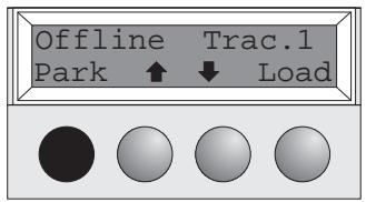
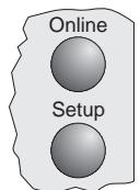
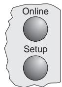
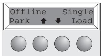
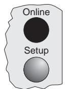
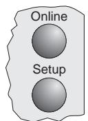
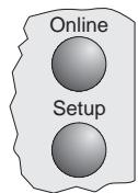
Offline mode
Step feeds, line feeds and form feeds can be performed via the control panel only in this mode (see page 15).
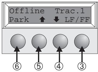
① Sets the printer to Offline mode.
② Sets the printer to Setup mode.
③ If no paper is loaded: Load key (see above). If paper is loaded: Short keypress: Line feed (LF) Long keypress: Form feed (FF)
④ Short keypress: Micro-step return Long keypress: Constant paper feed return
⑤ Short keypress: Micro-step forward Long keypress: Constant paper feed forward
⑥ Clears the paper path with paper loaded and activates paper path quick selection (see page 14).
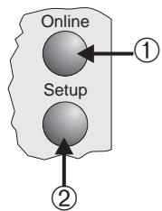
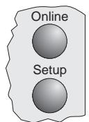
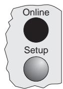
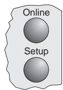
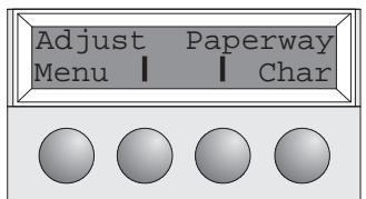
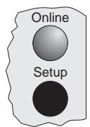
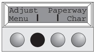
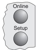
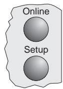
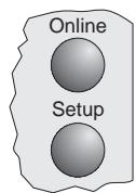
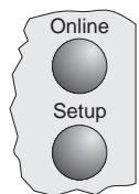
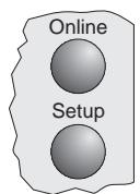
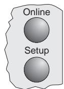
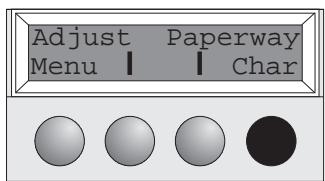
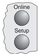
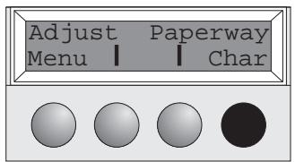
> Setup mode
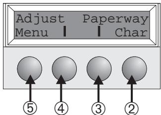
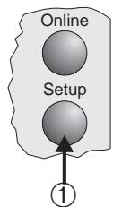
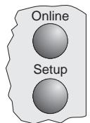
① Sets the printer to Setup mode. In this mode, the following settings are available:
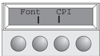
② Sets the font and the number of characters per inch (Char menu).
③ Paper path (Paperway menu)
④ Tear position and first printing line (Adjust menu)
⑤ Other menu settings (Menu)

Access to the other menu options is disabled by the manufacturer. For information on how to enable access to these options as well as about the options available, refer to the online documentation on the CD-ROM, chapter 1, Operation (Unlock the menu mode).
Installing the ribbon cassette
Remove any paper loaded into the printer.

Before opening the cover, make sure that the printer is switched off.
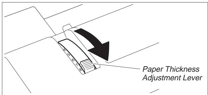
Set the Paper Thickness Adjustment Lever to the "8" position.
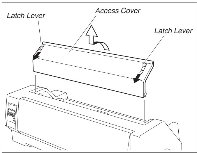
Pull the Latch Levers near the right and left ends on the Access Cover to the front, and detach the entire Access Cover.
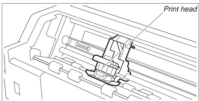
Move the Print head to approximately the center.

The Print Head may be hot. So please be careful not to touch the metal part of the Print Head.
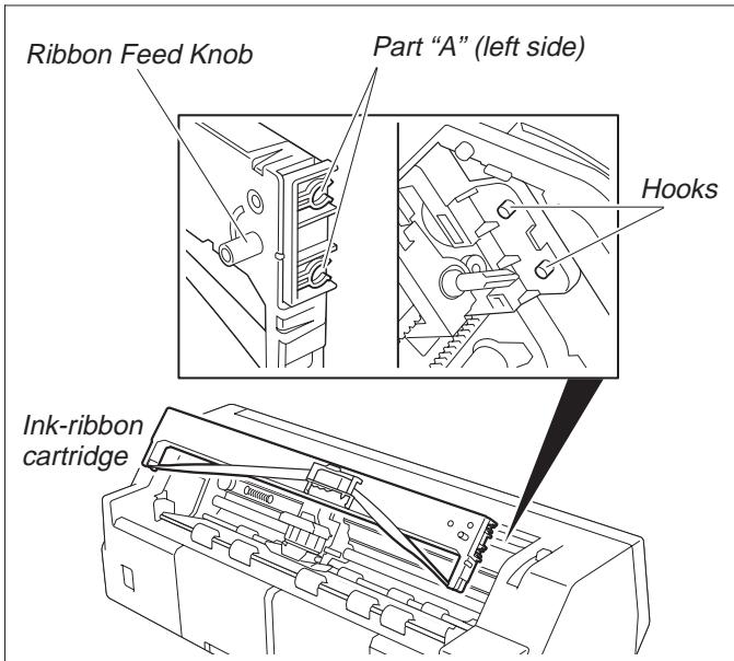
Align the part "A" on the left side of the Ink-ribbon Cartridge to the two hooks of the printer, push the cartridge all the way until it clicks. If there is resistance, push it while turning the Ribbon Feed Knob.
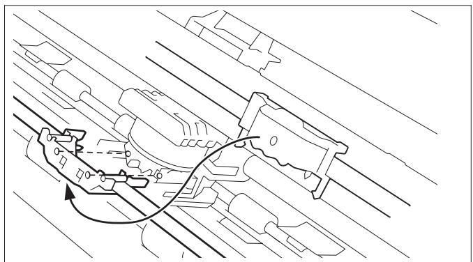
Detach the Ribbon Guide from the Ink-ribbon Cartridge.

Do not detach the shield that has been attached to the Ribbon Guide; it is necessary to protect the ribbon.
Put the Ribbon Guide between the Print Head and the Platen and push it all the way until it clicks.

When attaching the Ribbon Guide, be careful not to fold the ribbon. Also, pay attention to the shield so that it does not become damaged.
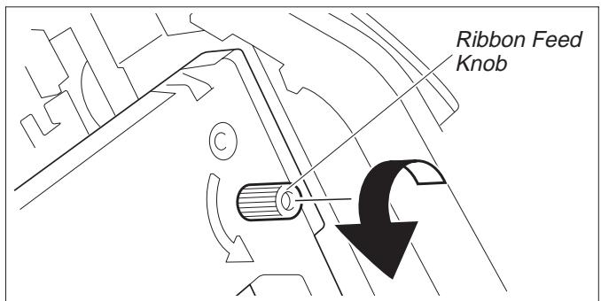
Turn the Ribbon Feed Knob in the direction indicated by the arrow to remove any slack in the ribbon.
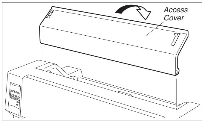
When the Ink-ribbon Cartridge setting is complete, attach the Access Cover.
Set the Paper Thickness Adjustment Lever in accordance with the thickness of the paper to be used. Refer to page 18 (Setting the print head gap).
Loading paper

Only use paper which is suitable for this printer. For more information, refer to the online documentation on the CD-ROM, Appendix C (Specification).
> Cut Sheet paper
Cut Sheet Paper is to be inserted from the front of the printer. The post-print paper can be fed out from the rear or the front. Please refer to the online documentation on the CD-ROM, Chapter 1, Menu description table.
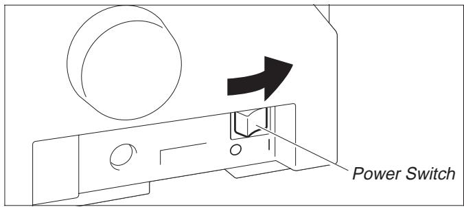
Turn the Power Switch of the printer ON ("I").
Adjust the Paper Thickness Lever according to the type of paper to be used. Refer to page 18 (Setting the print head gap).
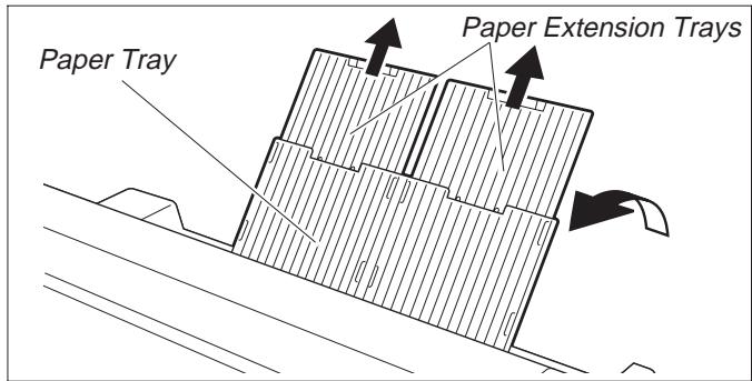
Stand the Paper Tray up in the direction indicated by the arrow. While holding the Paper Tray, pull up the Paper Extension Trays.
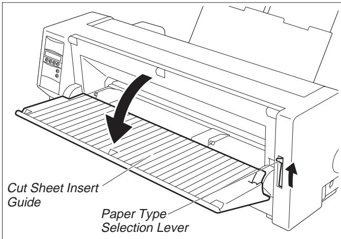
Set the Paper Type Selection Lever to Cut Sheet Paper mode. Make sure that the printer is in Single Sheet mode. For how to select Single Sheet mode refer to page 14 (Paper path quick selection).
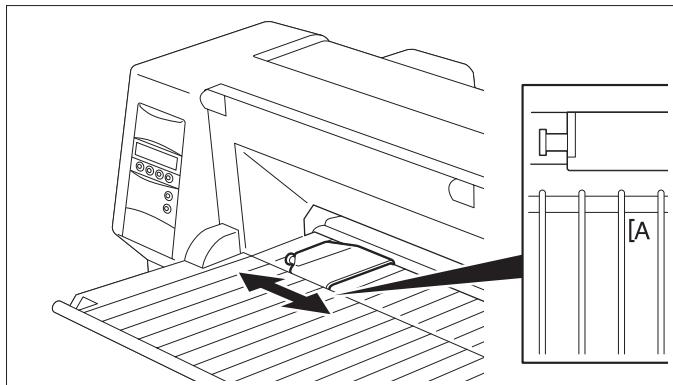
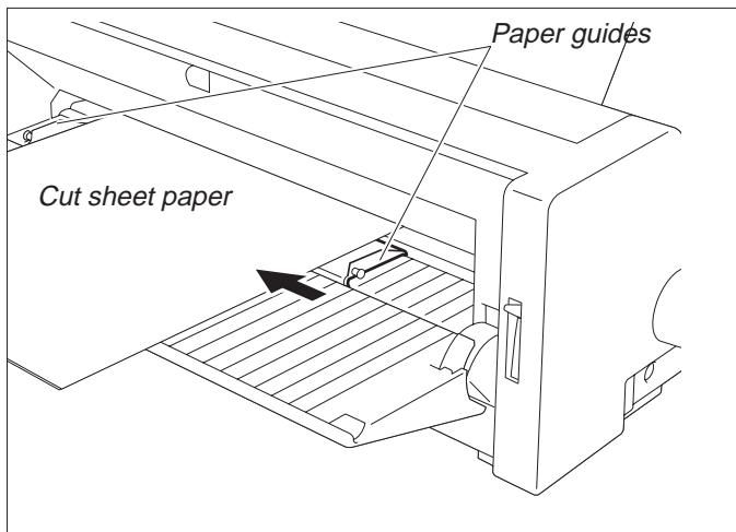
Determine the left margin by moving the Left Paper Guide left or right. (The “[A]” mark indicates the standard print start position.)
Place a sheet of paper aligned to the Left Paper Guide, and adjust the Right Paper Guide to the right edge of the paper.
Insert the paper between the Left and Right Paper Guides. The paper is automatically fed to the print start position and the printer is ready to print.

The paper feed-out capacity is about 30 sheets in case 55Kg -paper (ream) is used and the post-print paper is set to feed out to the rear side. When the post-print paper is set to feed out to the front, the paper must be removed sheet by sheet.
Printer in fanfold paper mode
Set the Paper Thickness Adjustment Lever according to the type of paper to be used. Refer to page 18 (Setting the print head gap).
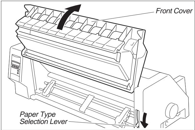
Set the Paper Type Selection Lever to Continuous Form Feed Paper mode.
Open the Front Cover to its upright position until it snaps in. This prevents unexpected closing of the cover.
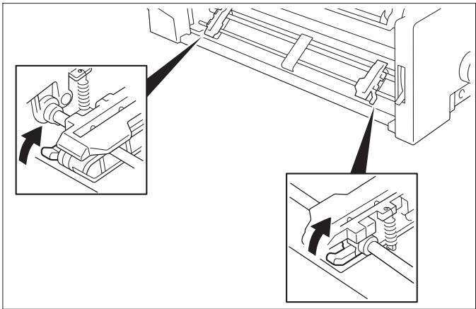
Stand the Left and Right Tractor Fixing Levers up (in the direction indicated by the arrow), and release the locks.
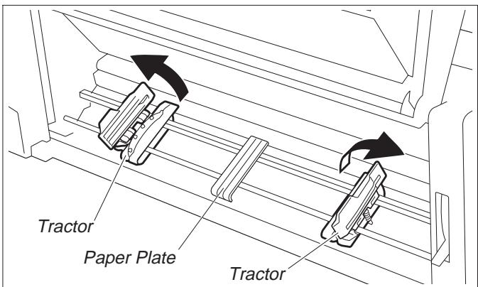
Open the Flaps of the Left and Right Tractors.
Match the Left and Right Tractors to the paper width.
Locate the Paper Plate in the center between the Left and Right Tractors.
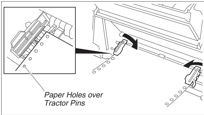
With the printing side of the paper facing up, fit the feeding holes on the left edge of the paper over the Left Tractor pins and close the Paper Flap.
Fit the feeding holes on the right edge of the paper over the Right Tractor pins, and close the Paper Flap.

To avoid paper jams, ensure that the same left and right feeding holes are used, and placed over tractor pins of the same level.
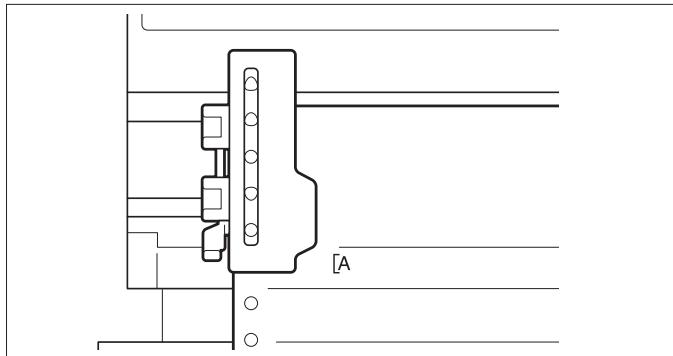
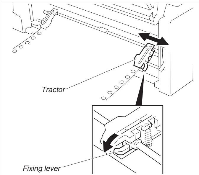
After the paper is set, adjust the left margin by moving the Tractors left or right. The “[A] mark is the standard print start position.
Push down the Left Tractor Fixing Lever to lock the Left Tractor.
Move the Right Tractor to remove any paper slack, and then push down the Fixing Lever to lock it in place.

If the paper slack cannot be removed by moving the Right Tractor alone, adjust the position of the Left Tractor.
Be careful not to stretch the paper so much that it tears.
Switch on the printer.
The active feeder (Trac.1) is displayed.
Paper is automatically fed when the printer is in Online status and receives data from the computer.
Press the Load key to load paper before printing.
Changing the paper type
Paper path quick selection


You can change the paper type (the paper path) either using the paper path quick selection feature or via the Setup menu.
First cut the fed-out portion of a Continuous Form Feed Paper at the perforated line. To do this, proceed as follows.
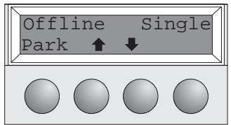
Make sure that the printer is in Offline status; press the Online key, if necessary. Press the Park key.
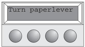
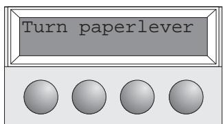
If fanfold paper is in the printer, it is transported to the tear position. "Tear paper off" appears on the display. Press any key.
If a single sheet is loaded in the printer, it is ejected.
Select the desired paper path by pressing one of the I keys, in our example Single.

If you do not make a selection within 5 seconds, the printer exits the menu.
The printer returns to Offline mode.
The display toggles between...
and...
Set the Paper Type Selection Lever to Cut Sheet Paper mode (see page 11 Loading paper).
The display toggles between...
Stand the Paper Tray up in the direction indicated by the arrow. While holding the Paper Tray, pull up the Paper Extension Trays.
Determine the left margin by moving the Left Paper Guide left or right.
Place a sheet of paper aligned to the Left Paper Guide, and adjust the Right Paper Guide to the right edge of the paper. Insert the paper between the Left and Right Paper Guides. The paper is automatically fed to the print start position (see page 11 Loading paper).

Press the Online key to make the printer ready for operation.
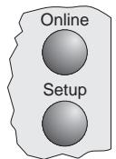
Paper transport
Loaded paper (fanfold paper/single sheets) can be transported in the printer in different ways.
Make sure that the printer is in Offline status; press the Online key, if necessary.
① Short keypress: Line feed (LF) is initiated Long keypress: Form feed (FF) is initiated
② Short keypress: Paper is transported downwards step by step Long keypress: Continuous transport down
③ Short keypress: Paper is transported upwards step by step Long keypress: Continuous transport up
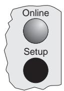
Using
Moving paper to the tear position
Fanfold paper can be transported to the tear position by pressing the Tear key.

Make sure that the printer is in Online status. Press the Tear key. The printer moves the perforation edge of the fanfold paper to the tear edge.
The display toggles between...

and...

Press the Exit key after having torn off the paper. The printer moves the paper back to the first printing position.
Settings (I)
Setting the tear position
If the tear position of the paper is not aligned with the tear edge of the printer, you can adjust it.

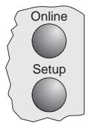
Press the Setup key. The printer changes to Setup mode.


Press the Adjust key.


Press the Tear key.
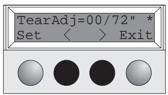
Press the < or key to move the perforation to the appropriate position. Confirm the setting by pressing the Set key. The printer returns to its initial status.

The correction made (a maximum of approx. 2.5cm [1"] in both directions) will be retained after printer power-off.
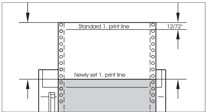
Setting the first printing line (TOF)
You can use the TOF function to set the position of the topmost printing line individually for each paper source and each menu.

You should adjust the tear position (see above) before using the TOF function (when using fan-fold paper).
Press the Setup key. The printer changes to Setup mode.
Press the Adjust key.


Press the TOF key.
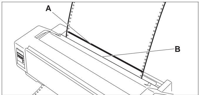
The bottom edge of the currently valid first printing line A of the paper is transported to the tear edge B .
The factory setting for the first printing position is 12/72".
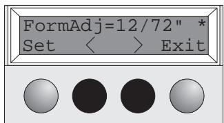
Press the < or > key to move the first printing line to the appropriate position. You can set values from 0 to 220/72" for fanfold paper, from 0 to 72/72" for single sheets.
Confirm the setting by pressing the Set key. The printer returns to its initial status.

The setting made will be retained after printer power-off. For more detailed information, refer to the online documentation on the CD-ROM, chapter 3 (Mechanical adjustments to the printer).
Settings (II)
Setting the print head gap
The printer has been provided with a Paper Thickness Adjustment Lever for adjusting the print head gap
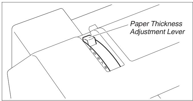
To obtain optimum print quality, the gap between the Print Head and the Platen needs to be adjusted according to the thickness of the paper to be used.
The following table shows the adjustable range:
| Number of Copies/Thickness of Paper | Ream (kg) | g/m2 | Lever Position |
| Original only ThinNormalThick | 45–5555–7777–110 | 50–6565–9090–130 | 11–22 |
| Original + 1 | 34/34 | 40/40 | 2–3 |
| Original + 2 | 34/34/34 | 40/40/40 | 2–4 |
| Original + 3 | 34/34/34/34 | 40/40/40/40 | 3–4 |
| Original + 4 | 34/34/34/34/34 | 40/40/40/40/40 | 4–5 |
| Original + 5 | 34/34/34/34/34/34 | 40/40/40/40/40/40 | 5–6 |
| Postal Card | 110 | 130 | 3 |
| Reserved | — | — | 7–8 |

- "Ream" is a unit of paper thickness, indicating the weight in kg, of 1,000 cut sheets at 788 mm x 1091 mm.
- When printing the original sheet only, Cut Sheet Paper of 45kg and thicker or Continuous Form Feed Paper of 50kg and thicker can be used.
- When the Paper Thickness Adjustment Lever is set higher than appropriate, the printout will appear scratchy and the print head and ribbon lives will be shortened.
Changing paper in Setup mode
From fanfold paper to single sheet mode

When fanfold paper was in use and you want to change over to single sheet mode, proceed as described below.
You do not need to remove the fanfold paper.


Cut the fed-out portion of the Continuous Form Feed Paper at the perforated line. To do this, proceed as follows.
Press the Setup key. The printer changes to Setup mode.

Press the Paperway key. The printer changes to the paper path menu.
Press or to change to Single (sheet) operating mode. The currently valid setting (Tractor 1) is marked by a “ ”.
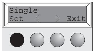
Confirm the setting by pressing the Set key.
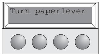
The input is acknowledged by an acoustic signal and the fanfold paper is transported to the tear position. Cut the fed-out portion of the Continuous Form Feed Paper at the perforated line.
In the display appears...
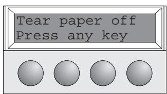
Press any key.
The printer returns to its initial status and the fanfold paper is transported to the park position.
The display toggles between...
and...

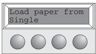
Set the Paper Type Selection Lever to Cut Sheet Paper mode.
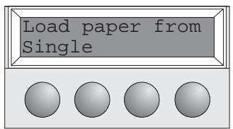
In the display appears...
Stand the Paper Tray up and pull up the Paper Extension Trays (see page 10). Place a sheet of paper aligned to the Left Paper Guide, and adjust the Right Paper Guide to the right edge of the paper.
Insert the paper between the Left and Right Paper Guides. The paper is automatically fed to the print start position (see page 11).

Press the Online key to make the printer ready for operation.
From single sheet to fanfold paper mode
When single sheets were in use and you want to change over to fanfold paper mode, proceed as described below.
Make sure that fanfold paper is loaded. Refer to page 12 (Loading Fanfold Paper) for details.

Pull down the Paper Extension Trays and fold the Paper tray down.
Press the Setup key. The printer changes to Setup mode.

Press the Paperway key. The printer changes to the paper path menu.
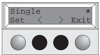
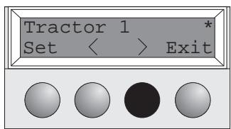
Press < or to change to Trac.1 (fanfold paper) mode.
The currently valid setting (Single) is marked by a .

Confirm the setting by pressing the Set key. An acoustic signal acknowledges the input.

The display toggles between...
and...
Shift the Paper Type Selection Lever to the position needed. The printer is now ready for printing fanfold paper. Press the Online key to make the printer ready for operation.
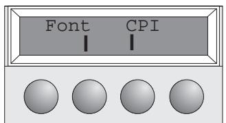
Selecting a font
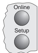
You can use the Font key to select fonts in Setup mode.
Press the Setup key.
Press the Char key.
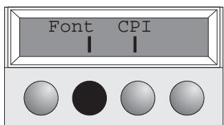
Press the Font key.
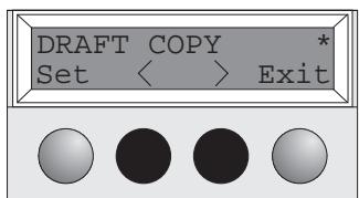

Press the < or key to select the desired font. Confirm your selection by pressing the Set key.

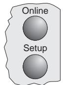
Press the Setup key. The printer returns to its initial status.
You can also press the Online key. The printer changes directly in Online mode.

The selection made will not be retained after printer power-off. For information on how to select a font permanently, refer to online documentation on the CD-ROM, chapter 1 (Menu description table).
Setting the character pitch
You can use the CPI key to set the character pitch in Setup mode.
Press the Setup key.
Press the Char key.
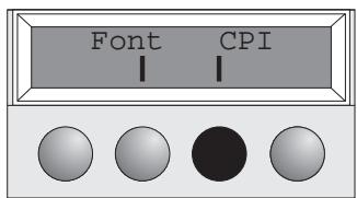
Press the CPI key.
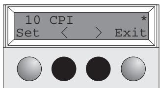
Press the < or ≥ key to select the desired pitch. Confirm your selection by pressing the Set key.

Press the Setup key. The printer returns to its initial status.
You can also press the Online key. The printer changes directly in Online mode.
STOP
The selection made will not be retained after printer power-off. For information on how to select a font permanently, refer to online documentation on the CD-ROM, chapter 1 (Menu description table).
Specifications
Printer specifications
| 9 | 24 | ||
| Printing method | serial printing with 9-pin matrix print head | serial printing with 24-pin matrix print head | |
| Print width | narrow printer 80 characters at 10 cpi wide printer 136 characters at 10 cpi | narrow printer 80 characters at 10 cpi wide printer 136 characters at 10 cpi | |
| Print speed (bidirectional) | HS-Draft/Draft Copy 360 cps at 10 cpi Draft 270 cps at 10 cpi NLQ/LQ 65 cps at 10 cpi | HS-Draft/Draft Copy 330 cps at 10 cpi Draft 250 cps at 10 cpi NLQ/LQ 70 cps at 10 cpi | |
| Character densities | 5, 6, 7,5, 8,6, 10, 12, 15, 17.1, 20 cpi | 5, 6, 7,5,8,6, 10, 12, 15, 17.1, 20 cpi | |
| Graphics print density | horizontal 240 dpi / vertical 144 dpi | horizontal 360 dpi / vertical 180 dpi | |
| Ribbon life | 4 million char. | 4 million char. | |
| Acoustic noise level | ca. 55 dB (A) | ca. 55 dB (A) | |
| Dimensions | narrow printer 485 x 206 x 245 mm (W x H x D) wide printer 625 x 206 x 245 mm (W x H x D) | narrow printer 485 x 206 x 245 mm (W x H x D) wide printer 625 x 206 x 245 mm (W x H x D) | |
| Weight | narrow printer 9 kg / wide printer 11 kg | narrow printer 9 kg / wide printer 11 kg | |
| Power supply | USA/Canada AC 120 V ±10% / 60 Hz ±3% Europe AC 230 V ±10% / 50 Hz ±3% | USA/Canada AC 120 V ±10% / 60 Hz ±3% Europe AC 230 V ±10% / 50 Hz ±3% | |
| Power consumption | at 100% throughput < 60 VA in the Ready state < 10 VA | at 100% throughput < 60 VA in the Ready state < 10 VA | |
| Operating environment | Temperature 10°C to 40°C Humidity 20% to 80% | Temperature 10°C to 40°C Humidity 20% to 80% | |
| Print head specifications | Number of pins 9 Pin diameters 0,3 mm Number of copies 1 original + 5 copies | Number of pins 24 Pin diameters 0,2 mm Number of copies 1 original + 3 copies | |
| Interface buffer | max. 40 kB | max. 40 kB | |
| Regulations | UL 1950, VDE-GS, CE, FCC Class B, UL/ULc | UL 1950, VDE-GS, CE, FCC Class B, UL/ULc | |
> Paper specifications
| Cut sheets | Paper weight | 60 – 120 g/m2 |
| Width | narrow printer: 76 – 220 mm / wide printer: 76 – 420 mm | |
| Length | 76 – 559 mm | |
| Fanfold paper | ||
| Simple forms | Paper weight | 60 – 120 g/m2 |
| Width | narrow printer: 76 – 254 mm / wide printer: 76 – 420 mm | |
| Length | 76 – 559 mm | |
| Sets of forms | Paper weight | original: 45 – 65 g/m2 / copy: 45 – 56 g/m2 / last page: 45 – 65 g/m2 |
| Width/Length | see simple forms | |
| Form thickness | max. 0,5 mm | |
| Number of copies | 1+5 (9 wire) / 1+3 (24 wire) |

For more information on printer specifications and paper specifications, refer to the online documentation on the CD-ROM.
Accessories
Ribbon cassettes
Narrow printer: Part No. 044 829
Wide printer: Part No. 044 830
A工程技术 plan, a design and test plan, a design and test plan, a design and test plan for the project.
All rights reserved. Translations, reprintng or copyi ng by any means of this manuall complete or in part or in any different form requires our explicit approval. We reserve the right to make changes to this manua without notice. All care has been taken to ensure accuracy of information contained in this manual. However, we cannot accept responsibility for any errors or damages resulting from errors or inaccuracies of information herein."
"CENTRONICS" is a trademark of Centronics Data Computer Corporation.
"EPSON" is a trademark of Epson America Incorporated.
"IBM" is a trademark of International Business Machines Corporation.
"MS-DOS" is a trademark of Microsoft Corporation.
"Windows", "Windows 95", "Windows 98" and "Windows NT" are trademarks of Microsoft Corporation.
WARENZEICHEN
Tally Representative
Park Place Moscow
office D-206
Leninsky Prospekt 113/1
117198 Moscow
Russia
Phone: +7 502 256 56 40
Inside C.I.S.:095 956 56 40
Fax: +7 502 256 56 41
Inside C.I.S.:095 956 56 41
http://www.Tally.com
U.S.A.
Tally Corp.
P.O.Box 97018
8301 South, 180th Street
Kent, WA 98032
U.S.A.
Phone: +1 425 25155 00
Fax: +1 425 25155 20
http://www.Tally.com
UNITED KINGDOM
Tally Limited
Molly Millars Lane
Wokingham, Berkshire
RG41 2QT
England
Phone: +44 118 978 8711
Fax: +44 118 979 1491
http://www.Tally.co.uk
CANADA
Tally Corp.
125 Traders Boulevard, 9
Missisauga, Ontario L4Z 2E5
Canada
http://www.Tally.co.at
SPAIN
Tally SRL
Aleixandre 8, 2^
28033 Madrid
Espana
Phone: +34 91 7219 181
Fax: +34 91 7219 936
http://www.Tally.it

- The printer at a glance 3
- Installation 5
- Control panel 7
- Installing the ribbon cassette 8
- Loading paper 10
- Changing the paper type 14
- Paper transport 15
- Using 15
- Settings (I) 16
- Settings (II) 18
- Specifications 23
- Accessories 24
- Introduction
- Symbols used in this manual
- Important safety instructions
- Using the online documentation
- Troubleshooting
- The printer at a glance
- Installation
- Connecting the printer
- > Switching the printer on and off
- Control panel
- > Online mode
- Offline mode
- > Setup mode
- Installing the ribbon cassette
- Loading paper
- > Cut Sheet paper
- Printer in fanfold paper mode
- Changing the paper type
- Paper path quick selection
- Paper transport
- Using
- Settings (I)
- Setting the tear position
- Setting the first printing line (TOF)
- Settings (II)
- Setting the print head gap
- From single sheet to fanfold paper mode
- Selecting a font
- Setting the character pitch
- Specifications
- Printer specifications
- > Paper specifications
- Accessories
- Ribbon cassettes
- WARENZEICHEN
- U.S.A.
- UNITED KINGDOM
- CANADA
- SPAIN
Brand : TALLY
Model : T2130-9
Category : Printer