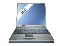
VISION 450T - Laptop MAXDATA - Free user manual and instructions
Find the device manual for free VISION 450T MAXDATA in PDF.



| Product type | Laptop |
| Brand | MAXDATA |
| Model | VISION 450T |
| Processor | Intel Pentium III (450/500/6XX MHz) with SpeedStep technology |
| RAM | Up to 512 MB SDRAM (2 SO-DIMM slots, 144 pins, 3.3 V) |
| Display | 14.1" TFT LCD XGA (1024x768) or 13" DSTN (depending on model) |
| Storage | 2.5" EIDE hard drive up to 6.4 GB, 24X CD-ROM drive, 3.5" 1.44 MB floppy drive |
| Audio | ESS SOLO-1 chipset, built-in stereo speakers, built-in microphone, headphone and microphone jacks |
| Connectivity | 1x VGA, 1x parallel, 1x serial, 1x USB, 1x PS/2, 1x RJ-11 modem, 1x RJ-45 10/100 LAN, 1x S-Video, 1x infrared (IrDA FIR) |
| Power | Ni-MH 10-cell 48 Wh or Li-Ion 8-cell 47.4 Wh battery, AC adapter 100-240 V, 50-60 Hz |
| Dimensions | 315 x 256 x 39.5 mm |
| Weight | Approximately 2.8 kg (with CD-ROM and floppy drive) |
| Compatible operating system | Windows 95/98/2000, Windows NT 4.0 |
| Special features | SpeedStep technology, DualView function (independent dual display), accelerated DVD/MPEG2 playback |
| Maintenance and cleaning | Turn off and unplug before cleaning; use a soft damp cloth; do not use liquid or aerosol cleaners |
| Security | BIOS user and supervisor password, Kensington lock, boot sector protection |
| Spare parts and repairability | Removable and upgradeable hard drive and DIMM memory; replaceable battery |
Frequently Asked Questions - VISION 450T MAXDATA
User questions about VISION 450T MAXDATA
0 question about this device. Answer the ones you know or ask your own.
Ask a new question about this device
Download the instructions for your Laptop in PDF format for free! Find your manual VISION 450T - MAXDATA and take your electronic device back in hand. On this page are published all the documents necessary for the use of your device. VISION 450T by MAXDATA.
USER MANUAL VISION 450T MAXDATA
The information in this user's manual is subject to change without notice.
THE MANUFACTURER OR RESELLER SHALL NOT BE LIABLE FOR ERRORS OR OMISSIONS CONTAINED IN THIS MANUAL AND SHALL NOT BE LIABLE FOR ANY CONSEQUENTIAL DAMAGES, WHICH MAY RESULT FROM THE PERFORMANCE OR USE OF THIS MANUAL.
The information in this user's manual is protected by copyright laws. No part of this manual may be photocopied or reproduced in any form without prior written authorization from the copyright owners.
Copyright April, 2000
All rights reserved.
Microsoft and Windows are registered trademarks of Microsoft Corporation. DOS, Windows 95/98/2000/NT are trademarks of Microsoft Corporation.
Product names mentioned herein may be trademarks and/or registered trademarks of their respective owners/companies.
The software described in this manual is delivered under a license agreement. The software may be used or copied only in accordance with the terms of the agreement.
TABLE OF CONTENTS
PREFACE
Symbols and Conventions
Protecting Your Notebook - Avoid Abusive Handling and Adverse Environment
Section Summaries
1. GETTING TO KNOW THE BASICS
Performance Features (1-2,3)
System at a Glance (1-4)
Top View (1-4,5,6)
Rear View (1-6,7)
Right-side View (1-8)
Lift-side View (1-9)
Bottom View (1-10,11)
LED Status Indicators (1-11,12)
LED System Indicators (1-13)
Keyboard (1-14)
Function (Hot) Keys (1-15)
2. BIOS SETUP AND SECURITY
Entering the BIOS Setup Screen (2-3)
Leaving the BIOS Setup Screen (2-3)
BIOS Action Keys (2-3)
Modifying the BIOS Settings (2-4)
The Setup Main Menu (2-4)
The Menu of Standard CMO Setup (2-4,5,6)
The Menu of Advanced CMO Setup (2-7, 8)
The Menu of Power Management Setup (2-9,10)
The Menu of Peripheral Setup (2-10,11)
The Security Issue by Using Password Protection (2-12)
The Option of Auto Detect Hard Disk (2-12)
The Option of Auto Configuration with Optimal Settings (2-12)
The Option of Auto Configuration with Fail-safe Settings (2-12)
The Option of Save Settings And Exit (2-12)
The Option of Exit Without Saving (2-12)
3. BATTERY POWER AND POWER MANAGEMENT
The Battery Pack (3-2)
Ni-MH / Lithium-Ion Battery (3-2)
Actions to Battery Warning (3-3)
Removing and Installing the Battery Pack (3-4,5)
To Detach the Battery Pack (3-4)
To Install the Battery Pack (3-5)
Charging the Battery and Charging Time (3-5)
Checking the Battery Level (3-6)
Prolonging the Battery's Life and Usage Cycles (3-6)
Using Power Management (3-7)
Suspend Mode (3-7)
The Suspend Button (3-8)
The LCD Panel Switch (3-8)
Power Consumption of the LCD Panel (3-8)
Creating Save To Disk Partition (or File) (3-9)
Windows 95/98 Power Management Feature (3-10)
4. UPGRADING YOUR NOTEBOOK
Upgrading the Hard Disk Drive (4-2)
Expanding the Hard Disk Drive (4-3,4,5)
Upgrading the System Memory (4-6)
Expanding the DIMM Module in the Original Socket (4-7,8,9)
Installing the DIMM Module in the Expansion Socket (4-10)
Removing the DIMM Module in the Expansion Socket (4-11)
5. TROUBLESHOOTING
First Step (5-2,3)
Audio Problems (5-4)
Hard Disk Problems (5-5,6)
CD-ROM Problems (5-6)
Floppy Disk Problems (5-7)
Display Problems (5-7)
Keyboard and Pointing Device Problems (5-8,9)
COMS Problems (5-9)
Infrared Problems (5-10,11)
Memory Problems (5-11)
Modem Problems (5-12)
Network Problems (5-13)
PC Card (PCMCIA) Problems (5-13,14)
Performance Problems (5-14,15)
Power, Start, and Battery Problems (5-15)
Printing Problems (5-16)
Serial, Parallel, and USB Problems (5-17)
Appendix A Product Specification
Appendix B Special VGA Functions
Windows 98 Display Driver Installation / Update (B-2)
Using the DualView Function (B-3,4,5,6)
Appendix C Regulatory Notices
Preface
Using This Manual
This User's Manual contains general information about your notebook, hardware and software setup information, troubleshooting, and technical specifications.
Symbols and Conventions
The following conventions and symbols are used in this manual:
When keys are to be pressed at the same time, a plus (+) symbol is used. For instance, Fn+F7 means holding Fn and F7 keys at the same time.
The file names are printed in uppercase type. For instance, WELCOME.EXE.
When a series of clicking actions is needed in Windows O/S, [ ] and > symbols are used. For instance, [Start > Settings > Control Panel > Multimedia] means clicking the Start icon first, then the Settings, then the Control Panel, then the Multimedia icon.
When you need to make a selection with the touch pad (or mouse), you will be asked to select or click the item.
Note: Text in this format and symbol means specific instructions, commentary, sidelights, or any additional information or notes that you should be aware of.

Warning: Text is this format and symbol means that failures to comply with the given instructions or information could result in damage to your notebook or could cause bodily harm or loss of life.
Protecting Your Notebook - Avoid Abusive Handling and Adverse Environment Follow the advice below will help ensure that you get the most out of your Investment.
Your computer will serve you well if you take good care of it.
Do not expose the notebook to direct sunlight or place it near sources of heat.
- Do not subject it to temperatures below 0° C ( 32° F ) or above 50° C ( 122° F ).
Do not expose the notebook to magnetic fields.
Do not expose the notebook to moisture or rain.
Do not spill water or liquid on the notebook.
Do not subject the computer to adverse shock and vibration.
Do not expose the notebook to dust and dirt.
Do not place objects on top of the notebook to avoid damaging the notebook.
- Do not place the notebook on rocky surfaces, uneven work place, or any fabric/ cotton materials cause bad thermal settings, for instance, bed and blanket.
Here are some ways of taking care of your AC adapter.
Do not connect the adapter to any devices other than your notebook.
Do not step on the power cord or place heavy objects on top of it.
Carefully tuck away the power cord and any cables away from pedestrian traffic.
When unplugging the power cord, do not pull on the cord itself but pull on the plug.
- Keep the adapter away from children.
The total ampere ratings of the equipment plugged in should not exceed the ampere rating of the cord if you are using an extension cord.
The total current rating of all equipment plugged into a single wall outlet should not exceed the fuse rating.
Here are some ways of taking care of your battery pack.
Use only factory-original batteries of the same kind as replacements.
Turn off the power or enter suspend mode before removing or replacing batteries.
Do not tamper with the sealed battery pack.
- Keep the battery pack away from children.
Dispose of used batteries according to local regulations.
Do not expose the battery pack to fire and recycle them if at all possible.
When cleaning the notebook, observe these steps:
- Power off the notebook and remove the battery pack.
- Disconnect the AC adapter.
- Use a soft cloth dampened with water. Do not use liquid or aerosol cleaners.
Contact your dealer or see your service technician if any of the following occurs:
Notebook has been dropped or the body has been damaged.
Liquid has been spilled into the product.
The notebook does not operate normally.
SECTION 1
GETTING TO KNOW THE BASICS
This section introduces the features and components of the notebook.
Performance Features
High Performance Processor
The notebook is equipped with the supreme computing power of Intel Celeron Processor, which provides awesome performance and data processing with 128K integrated Level II Cache.
AGP Graphics
By adapting an 2D/3D video processor with integrated Super UltraAGP technology and advanced 64-bit graphic display interface, the system delivers AGP 4x performance, up to 2 GB/s memory bandwidth and perform high quality graphics capabilities.
Advanced 3D Graphics and Hardware Accelerated MPEG2/DVD Playback
Hardware accelerated playback gives you smooth video playback with no discernible frame drops. 3D graphics also lets your games achieve more realism.
Mass Storage Capability
The system offers upgradable hard drive, allowing users to increase the storage capacity as the need arises.
High Flexibility Design
The notebook provides one additional expansion compartment for the memory upgrade. User may increase the amount of memory by adding a dual inline memory module, and in any combination for system memory expansion up to 512 MB.
Large LCD Display
The active-matrix XGA 14.1-inch TFT display (or 13.0-inch DSTN XGA in some model) panel provides clear and brilliant color text and graphics.
Keyboard and Touch Pad
The full-size keyboard, supported two win98 keys, and the build-in touch pad device, located at the center of the ergonomic plamrest, increase the work efficiency and productivity.
Advanced Battery Pack
The state-of-the-art Nickel Metal Hydride battery or Li- ion battery enables longevity, lightweight, and fast recharging.
A Variety of Communications
The system provides a total communication solution for Network connection, Internet Access, and cableless data transmission. The built-in network adapter allows you to access and transmit data on the Local Area Network. The built-in 56-Kbps V.90 modem enables fast data and fax communication, without sacrificing a valuable PC Card slot. Your notebook's infrared transceiver allows for wireless point-to-point communication with other systems or devices equipped with an infrared port.
Audio Features
The system is equipped with internal audio record and playback functions, including 3D (three-dimensional) audio, 64-voices DirectX sound channel support, and built-in hardware wave-table.
Integrated I/O Ports
This notebook offers a full array of built-in I/O ports. The system is also equipped with a Universal Serial Bus port for a new generation of USB-compliant peripherals.
System at a Glance

Warning:
Do not place any heavy objects on the top of notebook when the latches are on. That may damage the display.
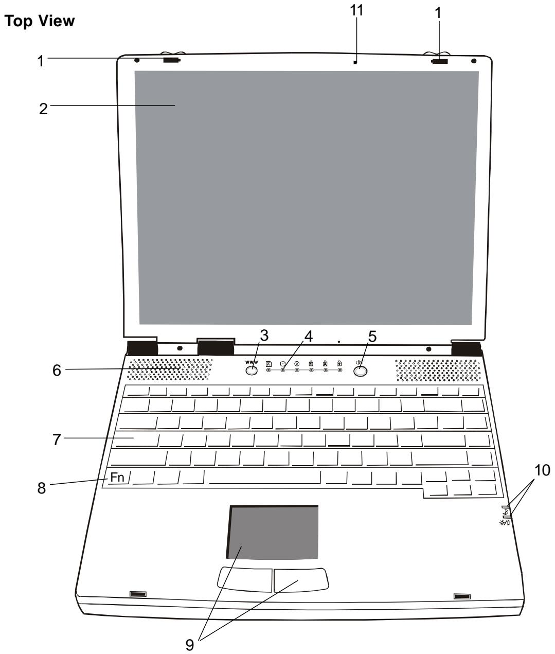
- LCD Latches
The left and right LCD latches lock/unlock the LCD panel.
- LCD Display Panel
This notebook is equipped by the liquid crystal display with XGA and SXGA resolution.
Note:
To use the Internet Hot Key feature, you must
- install the Windows network dialer with a valid Internet access account (from an ISP),
- install the special Internet Hot Key application contained in the factory CD-ROM (d:\Driver\ Qbrowse \ Setup.exe), and
- install Microsoft Internet Explore 4. 0 or higher.
3. Internet Hot Key WWW
The Internet Hot Key activates the modem dial-up networking process and opens the Internet browser automatically. (See side Note.)
4. LED Status Indicators
The LED Status indicators reveal the locking/unlocking of certain key functions and HDD/CD-ROM component status. (Refer to Page 1-11,12)
5. Power/Suspend Button

The power/suspend button turns the notebook on and off and it also acts as a system suspend key. This notebook uses a special one-button design. Press momentarily to turn on the system. Press and hold for at least 3~4 seconds to turn off the system. Once the system enters DOS/Windows, pressing the key momentarily will trigger system suspend mode. Press the power/suspend button again to return from the suspend mode. (See Section 3 for more details on system suspend function.)
6. Built-in Speakers
The built-in speakers output the sound in stereo.
7. Keyboard

The enhanced 86/87-key keyboard is used to enter data, including the Windows Start Key, Application Manu Key for windows95/98/NT4.0, embedded numeric keypad and cursor control keys (Refer to Page 1-14,15).
8. Fn Key
The Fn key is used with the function keys to activate the hot-key functions. (See Page 1-15)
9. Touch Pad
The touch pad is a built-in pointing device with functions similar to a mouse.
10. LED System Indicators
The Indicator shows the system's power/suspend status.
(Refer to Page 1-13)
11. Built-in Microphone
The microphone built-in provides an integrated source for adding sound to your applications or for using the speech functions of your applications. It takes the application, such as audio software, capable of using audio input to make use of the microphone.
Rear View
Note:
For the system running the Windows NT platform, USB function was not supported.

Warning:
Do not open the CPU heatsink/fan cover. Doing so may result in permanent system electrical damage, which is not covered by the manufacturer's warranty.
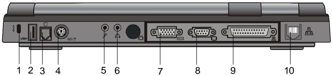
1. Kensington Security Anchor

This anchor can be used with a mechanical lock and Kensington-type cable. With this function, you may have the notebook locked to an appropriate location for security issue.
2. USB Port

The Universal Serial Bus (USB) port allows you to connect a wide variety of devices via the USB cable to your notebook and is also able to connect up to 128 devices through this single port, at very high data transfer rates of up to 12 Mbps (Mega-bits per second).
This port conforms to USB plug-and-play standards.
3. Modem Port

This is where you plug the phone jack (RJ-11) for activating fax/modem functions.
4. PS/2 Port
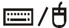
The notebook is designed to use one pointing device at once time. This is where you connect a external PS/2-compatible devices such as a mouse or keyboard.
5. Stereo Microphone Jack

The stereo microphone jack (3.5-mm diameter) is where you connect a microphone. To avoid the malfunction, please disable the built-in Microphone.
6. Stereo Headphone Jack

The stereo headphone jack (3.5-mm diameter) is where you connect the headphones or external speakers. With this function on, please disable the internal built-in speakers.
7. External VGA Port

The 15-pin VGA analog port is for connecting the external CRT monitor or projector.
8. Serial Port

This is where you connect a serial device via a 9-pin serial (RS-232) cable.
9. Parallel Port

The 25-hole parallel port is primarily where the printer signal cable attached. (The FDD module with the supplied parallel-port cable can be plugged into this port also.)
10. LAN Port

The port connects to a network hub via the RJ-45 cable and also conforms to 10Base-T and 100Base-TX transmission protocols.
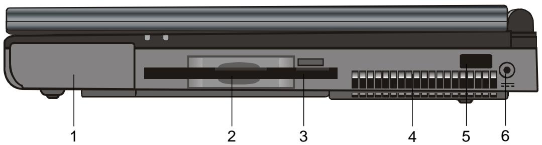
Right-side View
Note: For the system running the Windows NT platform, USB function was not supported.
- Battery Pack The battery pack is a built-in power source for the notebook.
- Floppy Drive
The floppy drive was also fixed inside the system.
- Floppy Eject Button With this button, you may have the floppy diskette ejected.
- Fan Grill The fan grill is where hot air is expended. Do not block this airway completely.
- Infrared Port Infrared Data Association (IrDA) compliant serial infrared port enables 4Mbps (FIR mode) cableless data transfer with IrDA 1.1-compatible external devices.
- Power Jack ( DC-in ) This is where the DC end of the AC Adapter connected to your machine.
Left-side View
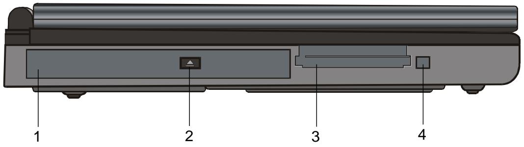
1. CD-ROM

The CD-ROM device was fixed inside the notebook.
2. CD-ROM Eject Button
The eject button opens the CD-ROM tray.
3. PC Card Slot
The slot is where PC Card (PCMCIA) is inserted.
A PC Card slot with connectors for two 3.3V/5V cards, and both of them support CardBus technology.
4. PC Card Eject Button
With this button, you may have the PCMCIA card ejected.
Note:
There are two kinds of types of CD-ROM might be installed as shipped. One is electrical and the other is mechanical. Basically, the mobile computer is equipped to the electrical CD-ROM. With this device, you can do the CD-ROM ejection only if the system is on. As for bundling the mechanical type, the ejection button works all the time, even the system is powered off. Please be also noted, the mechanical one is not available to eject the CD-Disk by performing Fn key under the running Windows 98 operating system.

Warning:
Do not open the CPU heatsink/fan cover and do not block this airway completely. Otherwise it may result in permanent system electrical damage or cause thermal issue which is not covered by the manufacturer's warranty.

Warning:
As upgrating your CPU, please be cautioned against the heatsink/fan. The axle of heatsink might be twisted by heavy press. It is not covered by the manufacturer's warranty.
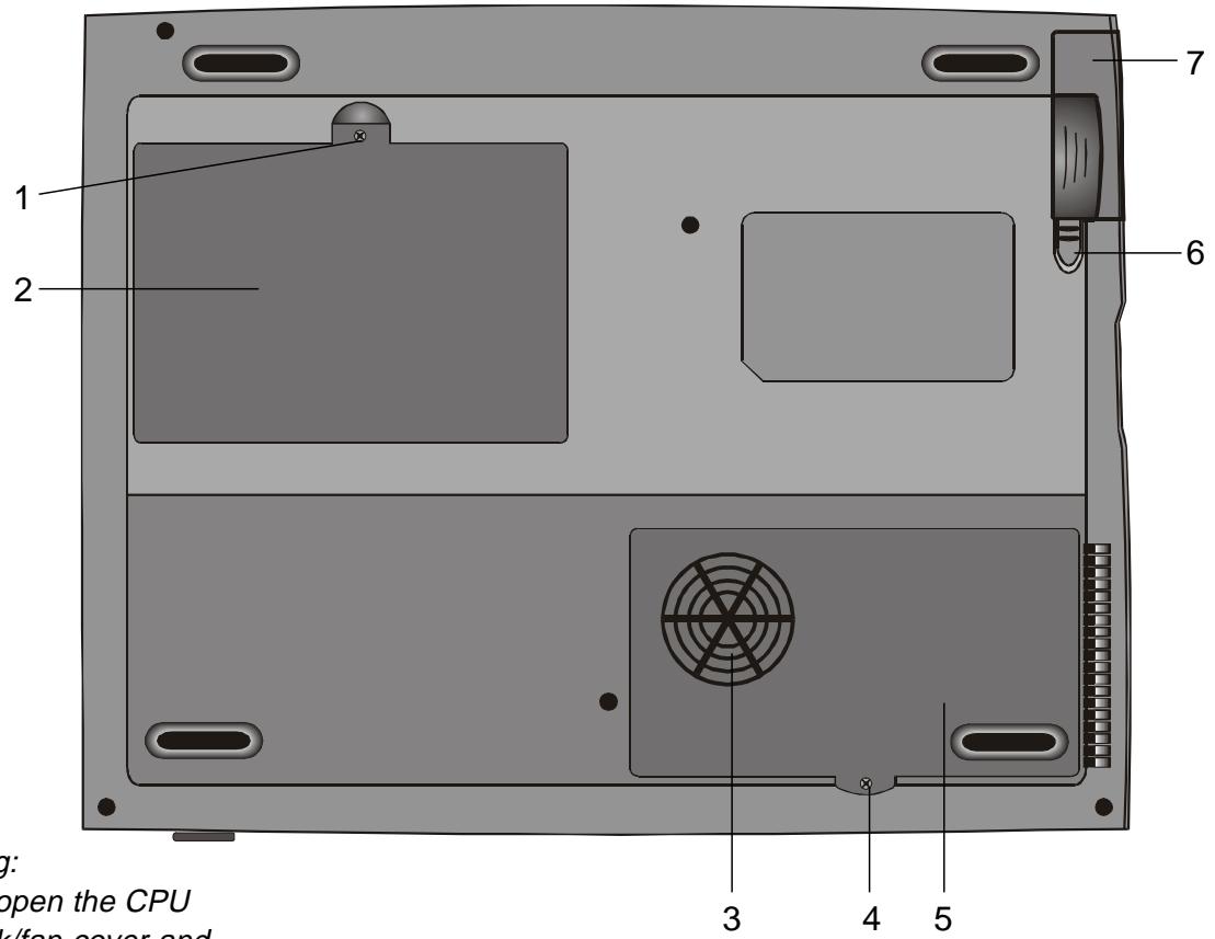
Bottom View
Fixing Screw
The fixing screw locks the hard disk drive bay cover, which prevents the hard disk drive from dust and dirt, in place.
Hard Disk Drive Bay
This is where the hard disk drive located. The hard disk drive stores all the system data. For the flexible design, the hard disk drive can be upgraded to a larger capacity. (Refer to Section 4 for instructions on a hard drive upgrade.)
3. CPU Heatsink/Fan Bay Cover
The CPU heatsink/fan bay is where the air is drawn into the notebook for internal thermal regulation. Do not block this airway completely. Do not remove this cover. There is no user-serviceable parts inside.
4. Fixing Screw
The fixing screw locks the CPU heatsink/fan bay cover, which prevents the CPU module from dust and dirt, in place.
5. CPU Heatsink/Fan Bay
The bay is where the CPU be installed.
6. Battery Latches
The battery latches locks or releases the battery pack.
7. Battery Pack

The battery pack is a built-in power source for the notebook.
LED Status Indicators
The indicators under the LCD display panel, show as follow, inform you the current operating status of your notebook. As a certain function is enabled, the represented indicator will illuminate. The icons or symbols are captured as follow and descipted in detail.
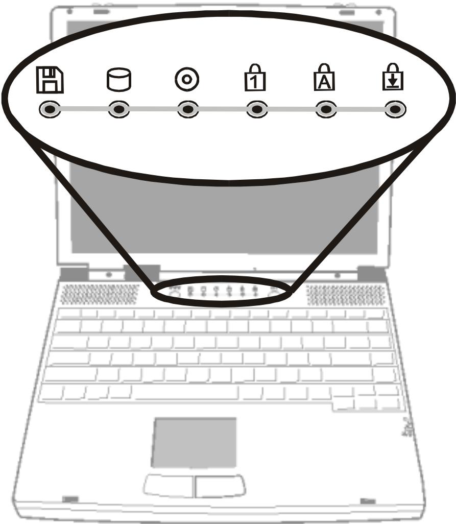
| LED Graphic Symbol | Indication |
| Green light indicates the floppy drive is being accessed. | |
| Green light indicates the hard drive is being accessed. | |
| Green light indicates the CD-ROM drive is being accessed | |
| Green light indicates the numeric keypad is activated. | |
| Green light indicates the cap-lock is activated. | |
| Green light indicates the scroll-lock is activated. |
LED System Indicators
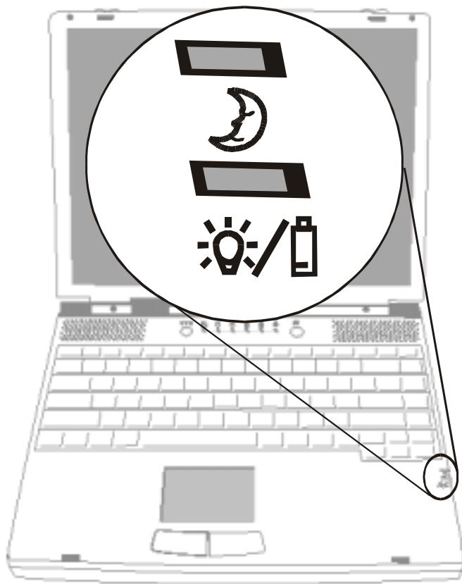
| Symbol | Indication |
| Yellow light indicates the notebook is in suspend mode. As LED is in flash, it means the notebook is in POS mode. LED would be off when it is in the STD mode. | |
| Blinking red light indicates the battery is being charged (the system is OFF.) Blinking orange light indicates the battery is being charged (the system is ON.) Blinking green light indicates the battery power is currently low. |
Keyboard
The notebook is designed to use one keyboard at once time. Please disable the built-in keyboard before activating the externl one.
The main interface of input in the portable PC would be the keyboard. The keyboard has all the functionality as a standard computing 101 typing keys. It provide the alternate functions as embedded numeric keypad, shortcut windows key, system operation hot keys. The description below present all the details you need to know.
The cursor (arrow) keys, which are located in the lower-right corner of keyboard, and the [Pg Up], [Pg Dn], [Home] and [End] keys, which are located along the edge of keyboard, allow you move the active cursor to various locations on the screen or within the document.
The [Ins] and [Del] keys at the bottom of the keyboard to the left of the cursor keys allow you to insert and delete characters. Your computer also has an embedded numeric keypad. Get more detailed information at Page 1-18 Embedded Numeric Key Pad.
Your keyboard also has two Windows 95 keys:

- Start Key with Windows logo:
This key allows you to pull up the Windows Start Menu at the bottom of the taskbar.

- Application Menu Key which looks like a menu with a cursor on:
This key brings up the popup menu for the current application that is Windows 95 compatible. This function is similar like a click of the right mouse botton.
Function (Hot) Keys
| Graphic Symbol | Action | System Control |
| Fn + F1 | Enters Suspend Mode. | |
| Fn + F2 | Mute | |
| Fn + F3 | Toggles between Battery Warning Beep on and off. | |
| Fn + F4 | Switches Display Mode: LCD-only, CRT-only and dual-display. | |
| Fn + F5 | Turns Speaker Volume up. | |
| Fn + F6 | Turns Speaker Volume down. | |
| Fn + F7 | Increases Display Brightness. | |
| Fn + F8 | Decreases Display Brightness. | |
| Fn + F9 | Increases Display Contrast. (DSTN Only) | |
| Fn + F10 | Decreases Display Contrast. (DSTN Only) | |
| Num Lock | Fn + Num Lock | Enables the embedded keypad to work in numeric mode. The keys function as a calculator. Use this mode when you need to do a lot of numeric data entry. An alternative would be to connect an external keypad. |
| Scroll Lock | Scroll Lock | Pressing the ScrLk key allows the screen to move one line up or down when you press or respectively. Scroll Lock may not work with some applications. |
Note:
For various system controls, press the Fn (Function) key and the Fx key simultaneously.
Note:
When use Fn+F5 or Fn+F6, volume control menu will not be updated immediately. After you re-open the menu, the volume bar will be updated to correct position.
SECTION 2
BIOS SETUP AND SECURITY
In this section, you will learn how to enter the BIOS Setup Menu and manipulate various hardware control settings. You will also learn how to use the built-in security features.
The Setup Utility is a hardware configuration program built into your notebook's BIOS (Basic Input/Output System). It runs and maintains a variety of hardware functions. It is a menu-driven software, which allows you to easily configure and change the settings.
The BIOS contains manufacture's default settings for the notebook's standard operations. However, there are occasions when you may be required to modify the default settings in the BIOS. For example, you may need to activate the BIOS setup program when a hardware change, such as an upgrade, occurs, or when you decide to customize the hardware settings to suite your specific needs.
The BIOS allows you to set up passwords to limit access to users. This is an important feature because a great deal of vital information is carried within the notebook nowadays. Unauthorized access can be prevented. Later in this chapter, you will learn how to use this security feature.
Entering the BIOS Setup Screen
First turn on the power. When the BIOS is performing the POST (Power-On Self Test), press DEL key to activate the AMIBIOS Setup Utility. Press DEL when you see the prompt "Press DEL to enter SETUP".
Leaving the BIOS Setup Screen
When you have finished modifying the BIOS settings, exit the BIOS. It takes a few seconds to record changes in the CMOS.
BIOS Action Keys
| Function Key | Command | Description |
| ESC | Exit | Leaves a sub-menu to return to the previous menu OR exits the BIOS setup while saving changes. |
| F2/F3 | Change Color | Changes the background color of the BIOS Setting Utility. |
| F10 | Save and Exit | Saves changes and reboots the notebook. |
| Select a field | Selects the next field. | |
| Select | Enters the value or selects the sub-menu. | |
| Select a menu | Selects the next. | |
| Select a menu | Selects the next left menu. | |
| Select an item | Selects the next upper item. | |
| Select an item | Selects the next lower item. | |
| PgUp | Lower value | Selects the next lower value within a field. |
| PgDn | Higher value | Selects the next higher value within a field. |
Note:
Under certain settings, the fields are grayed out.
Grayed out fields are not changeable.
Modifying the BIOS Settings
The AMIBIOS setup main menu is subdivided into few sub-menus as follow. Each menu item is described detailed in this section.
The Setup Main Menu
| AMIBIOS HIFLEX SETUP UTILITY VERSION 1.23b (c) 1999 AMERICAN MEGATRENDS, INC. ALL RIGHTS RESERVED | |||
| STANDARD CMOS SETUP ADVANCED CMOS SETUP POWER MANAGEMENT SETUP PERIPHERAL SETUP AUTO-DETECT HARD DISK CHANGE USER PASSWORD CHANGE SUPERVISOR PASSWORD AUTO CONFIGURATION WITH OPTIMAL SETTINGS AUTO CONFIGURATION WITH FAIL-SAFE SETTINGS SAVE SETTINGS AND EXIT EXIT WITHOUT SAVING | |||
| Esc: Exit | : Sel | F2/F3: Color | F10: Save & Exit |
The Menu of Standard CMO Setup
Standard CMOS Setup for changing time, date, hard dick drive type and etc. All standard setup options all described in this section.
| Item | Selections / Sub-menu | Description |
| Date | N/A | Type in the current date. It must be entered in MM/DD/YY format. |
| Time | N/A | Type in the current date. It must be entered in HH:MM:SS format. |
| Floppy Drive A: | Not installed 1.44 MB 31⁄2 inch | Choose one that fits your particular need. |
| Pri Master | Not installed Auto ARMD CD-ROM | Primary Master is where BIOS tries to boot from first. The primary master controls the hard drive. The drive capacity is displayed in this field. |
| Pri Slave | ||
| Sec Master | 1-46 User | The secondary master controls the CD-ROM drive. |
| Sec Slave | ||
| Boot Sector Virus Protection | Disabled Enabled | To enable or disuse the boot sector protection. BIOS would pop out a warning if any application or virus is trying to issue a disk format command to have boot sector written. |
If enabled, the following appears when a write is attempted to the boot sector. You may have to type "N" several times to prevent the boot sector write.
Boot Sector Write!!!
Possible VIRUS: Continue (Y/N)?
The following appears after any attempt to format any cylinder, head, or sector of any hard disk drive via the BIOS Hard Disk Drive Service:
Format!!
Possible VIRUS: Continue (Y/N)?
Note:
AMIBIOS
automatically
sets IDE drive
parameters.
Set the setting as "USER" to enter the MFM, ESDI, or DLL drive parameters.
Select "Not Installed" for SCSI Drive.
Choose "CDROM" option for ATAPI CD-ROM drive.
The Detailed Description of Hard Disk Drive Setting
Select Auto and let BIOS to configure the drive parameters automatically. After press "Enter", BIOS display the drive parameters. If the detected drive paramters were not correct or you're trying to enable the enhanced IDE feature, you may still change the value manually.
LBA Mode: (Large Mode)
Select "On" if the drive has a capacity larger than 540MB.
Blk Mode: (Block Mode)
Select "On" is to allow blocking data transmission.
32 Bit Mode:
Select "On" to allow data transmission in 32 bit.
PLO Mode:
It is suggested to select "Auto" to let BIOS arrange the PIO mode setting. If the selected PIO mode is not supported by the IDE drive, the hard disk drive won't work properly. If the drive PIO mode is known, you're certainly may select the appropriate PIO mode from 1 to 5.
Entering Drive Parameters
Any hard disk drive, Primary Master, Primary Slave, Secondary Master and Secondary Slave, to be configured as Hard Disk Drive Type between 1-46, you may need to enter the correct drive parameters.
The Decryption of Drive Parameters
| Parameter | Description |
| Type | The number for a drive with certain identification parameters. |
| Cyln | The number of cylinders in the disk drive. |
| Heads | The number of heads. |
| WPcom | The actual physical size of a sector gets progressively smaller as the track diameter diminishes. This parameter is the cylinder number on the disk surface where write precompensation begins. |
| Sec | The number of sectors per cylinder. MFM drives have 17 sectors per cylinder. RLL drives have 26 sectors per cylinder. ESDI drives have 34 sectors per cylinder. SCSI and IDE drives have even more sectors per cylinder. |
The Menu of Advanced CMOS Setup
Advanced CMOS Setup for configuring system options.
| Item | Selections / Sub-menu | Description |
| 1st Boot Device | Disabled IDE-0 Floppy CDROM | Set the type of device for the 1st boot drive that BIOS attempts to boot from after BIOS POST completes. |
| 2nd Boot Device | Set the type of device for the 2nd boot drive that BIOS attempts to boot from after BIOS POST completes. | |
| 3rd Boot Device | Set the type of device for the 3rd boot drive that BIOS attempts to boot from after BIOS POST completes. | |
| Boot Up NumLock | On Off | Turn the numeric keys on or off as system boots up. |
| Password Check | Setup Always | [Setup]: To enable the password check function every time when BIOS Setup is executed. [Always]: To enable the password check function every time the system boots. |
| CPU / DRAM Frequency | 66/66MHz, 66/100MHz, 100/100MHz, 100/133MHz, 133/133MHz, | Set the CPU and DRAM working frequency by the parameters as shown. Your notebook can't be booted if CPU does not support the frequency. (Refer to the warning below.) |

Warning:
Your notebook can't not be booted if the CPU does not support the working frequency set in BIOS. In this case, you need to reconfigure by following the instructions.
1) Power on the system and repeatedly press [Pg Up] key located along the edge of keyboard.
2) After the boot screen, press [Delete] key to activate the BIOS utility.
3) Go to Advanced CMOS Setup > CPU Base Frequency and restore it to default, 66/66MHz.
| Item | Selections / Sub-menu | Description |
| Plug and Play Aware OS | YesNo | [Yes]: The operating system in this computer will follow the Plug and Play specification. [No]: The operating system in this computer won't follow the Plug and Play specification. |
| Share Memory Size | Disabled4MB8MB16MB32MB | Set the size of memory allocation for VGA graphics support from system momery. [Disabled]: To disable memory allocation function. [4MB 8MB 6MB 2MB]:User may define the size of memory sharing. |
| Clear NVRAM | YesNo | [Yes]: Clear NVRAM. [No]: Not to Clear NVRAM. |
To set 8MB as VGA shared memory size in BIOS, the system would only display 56MB on the Power-On Self Test (POST) if the total memory size is 64MB.
Please refer the table below to your arbitration for proper momery sharing size of VGA graphic display in BIOS.
| VESA Standard Graphic Modes | Suggested Memory Sharing Size | |
| Resolution | Color Depth | |
| 640 X 480 | 16/256/32K/64K/16M Colors 120Hz NI | 1M |
| 800 X 600 | 16/256/32K/64K/16M Colors 120Hz NI | 1M |
| 1024 X 768 | 256/32K/64K/16M Colors 120Hz NI | 2M |
| 1280 X 1024 | 256/32K/64K/16M Colors 120Hz NI | 4M |
| 1600 X 1200 | 256/32K/64K/16M Colors 100Hz NI | 8M |
| 1920 X 1200 | 256/32K/64K/16M Colors 80Hz NI | 8M |
The Menu of Power Management Setup
Power management setup for configuring power management featuring.
| Item | Selections / Sub-menu | Description |
| Power Switch Type | On/Off Suspend | [On/Off]: Set the power switch type to On/Off function. [Suspend]: Set the power switch type to Suspend function. |
| Power Management | Disabled Enabled | To disable or enable the system power management function. |
| Suspend Mode | Disabled POS (S1) STD (S4) | [Disabled]: All system will run in fully speed. [POS (S1)]: Power On Suspend. The system will save its state to disk and power off. [STD (S4)]: Save To Disk. The system will save its state to disk and power off. |
| Standby Time Out | Disabled 1 Min, 2 Min, 3 Min, 4 Min, 5 Min, 10 Min 15 Min | Specify the period of inactivity before entering the Standby Mode. |
| Suspend Time Out | Disabled, 1 Min, 2 Min, 3 Min, 4 Min, 5 Min, 10 Min 15 Min, 20 Min, 30 Min | Specify the period of inactivity before entering the Suspend Mode. |
| Hard Disk Time Out | Disabled 1 Min, 2 Min 5 Min, 10 Min 15 Min | Specify the period of inactivity before hard disk spins down. |
| RTC Alarm Resume From Soft Off | Disabled Enabled | [Disabled]: The system ignores the RTC alarm and remains in suspend mode. [Enabled]: The system wakes up from the suspend mode as the RTC alarm. |
| RTC Alarm Date* | Every Day 1 ~ 31 | Set the date of RTC alarm. |
| RTC Alarm Hour* | 00 ~ 23 | Set the hour of RTC alarm. |
| RTC Alarm Minute* | 00 ~ 59 | Set the minute of RTC alarm. |
| RTC Alarm Second* | 00 ~ 59 | Set the second of RTC alarm. |
Item with *sign means:
The option is only available when the "RTC Alarm Resume From Soft Off" is enabled.
The Menu of Peripheral Setup
Configuration for the peripheral devices and its features.
| Item | Selections / Sub-menu | Description |
| OnBoard FDC | Auto | [Auto]:BIOS will configure the Floppy Disk Controller automatically. |
| Disabled | [Disabled]: The FDC is disabled. | |
| Enabled | [Enabled]: This FDC is enabled. | |
| OnBoard Serial Port A | Auto | [Auto]:BIOS will configure this port automatically. |
| Disabled | [Disabled]:This serial port will be disabled. | |
| 3F8/COM1 | [3F8/COM1 2F8/COM2 | |
| 2F8/COM2 | 3E8/COM3 2F8/COM4]:User may define the I/O port address of this serial port. | |
| OnBoard Serial Port B | 3E8/COM3 | |
| 2F8/COM4 | ||
| Serial Port2 Mode | IrDA FIR | This is to specify the type of infrared supporting function. [IrDA]: Standard serial IR communication. [FIR]: Fast IR communication. |
| IR Duplex Mode | Half Duplex Full Duplex | This option is to select the infrared transmission method. [Half Duplex]: The infrared transmission method as half duplex. [Full Duplex]: The infrared transmission method as full duplex. |
| IR DMA Channel | (DMA Ch) 0 (DMA Ch) 1 (DMA Ch) 3 | This is to configure the DMA channel used for FIR only but IrDA not be supported |
| On-Board Paral- lel Port | Disabled, Auto, 378, 278, 3BC | User may define the I/O port address of this parallel port, or disable this parallel port functor, or let BIOS determine this port automatically. . |
| Paral- lel Port Mode | Normal Bi-Dir EPP 1.9 EPP 1.7 ECP | [Normal]: The normal parallel port mode is used. [Bi-Dir]: (Bi-Directional) This allows data to transfer equally in both directions on parallel port. [EPP 1.9 EPP 1.7]: Enhanced parallel port for faster performance. [ECP]: Faster data exchange than EPP. |
| Paral- lel Port IRQ | AUTO | [AUTO]: BIOS will configure the IRQs of Parallel port automatically. |
| Paral- lel Port DMA Chan- nel | AUTO | [AUTO]: BIOS will configure the DMAs of Parallel port automatically. |
The Security Issue by Using Password Protection Two Levels of Password Protection
This BIOS provides a Supervisor. If you try to activate passwords, the Supervisor password must be set.
The passwords activate two different levels of protection security:
- Always requesting password every single time as the system is powered on.
- A password checking procedure pops up when BIOS utility is executed.
Have the Password Check item set in Advanced CMOS Setup Menu (refer to Page 2-10, The Menu of Advanced CMOS Setup).
The passwords are encrypted and stored in NVRAM. If the password protect is activated, an input 16-character password prompt appears. Make sure you write it down. If you forget it, you must have NVRAM erased and reconfigured.
The Option of Auto-Detect Hard Disk
By activation of this option, AMIBIOS will automatically detect the hard disk drive parameters. The Standard CMOS Setup menu would display after configuration of the hard drives.
The Option of Auto Configuration with Optimal Settings
It will automatically set all BIOS Setup options to a complete set of default settings when you choose this option. The Optimal settings are designed for maximum system performance, but may not work best for all computer applications. Particularly do not use the Optimal BIOS Setup options if your computer is experiencing system configuration problems.
The Option of Auto Configuration with Fail-Safe Settings
It will automatically set all BIOS Setup options to a complete set of default settings when you choose this option. The Fail-Safe settings are designed for maximum system stability, but not maximum performance. Choose the Fail-Safe BIOS Setup options if your computer is experiencing system configuration problems.
The Option of Save Settings And Exit
When you have completed the system configuration modification, choose this option to leave BIOS Setup with new parameters saved and to reboot the computer. So the new system configuration parameters can take effect.
SECTION 3
BATTERY POWER AND POWER MANAGEMENT
In this section, you will learn the fundamentals of power management and how to use it to achieve longer battery life.
In this section, you will learn how to operate your notebook on battery power, how to handle and maintain the battery pack, and learn about the system's unique Heuristic Power Management feature.
TFT display, central processor, hard disk drive, floppy disk drive are the major hardware subsystems that consume the most power. Power management deals how these key components should behave to conserve power. For example, you can have the system turn off its display after 2 minutes of inactivity to save power. Efficient power management can help you work longer sessions before having to recharge the battery.
The Battery Pack
Note: Make sure the battery is fully charged before using.
Note: In the Save To Ram mode, a fully charged battery loses its power in roughly 1 day. When not being used, the battery's power will deplete in 1-2 month.
Note: Do not touch the metal ends of the battery connector to avoid rusting.
When the notebook operates on battery power, the Battery LED indicator will be on.
Ni-MH / Lithium-Ion Battery
Your notebook uses an removable ten-cell Nickel Metal Hydride (Ni-MH) or eight-cell Lithium-Ion battery pack that provides power when you're away from an AC outlet.
This is the main battery, you should recharge it as it is drained. Besides the main battery, it is suggested that you should also have a second battery pack as the backup power solution in your traveling.

Warning:
Do not expose
battery packs to
temperatures below
0 degree Celsius (32
degree F) or above
60 degree C (140F).
This may adversely
affect the battery
pack.

Warning: If the "Battery Warning Beep" is disabled by the Fn + F3, the system won't generate the beep sounds.
Actions to Battery Warning
I. Low Battery Warning
Low battery occurs as the battery is in approximately 6 % of its power remaining. Before the Very Low Battery, the green power LED indicator blinks at the same rate as the system beeps once every 16 seconds.
II. Very Low Battery Warning
Very Low battery occurs as the battery is in approximately 3 % of its power remaining. Before the dead battery, the green power LED indicator blinks at the same rate as the system beeps once per 4- sec increment.
The signals alert you the low battery and require the restorative action before the hibernated system. Save your document, data, and close all the applications straightaway, or else you might lose all your current work. About 5-10 minutes of battery operating time remains. You may not to keep continue unless you plug in the AC adapter or replace the charged battery.
Installing and Removing the Battery Pack
Carefully observe the illustration for this operation.
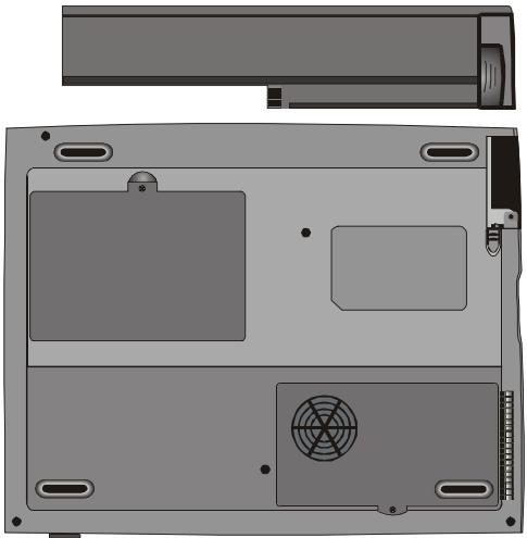
To Detach the Battery Pack:
- Position the notebook rear-side up on a flat and secured surface.
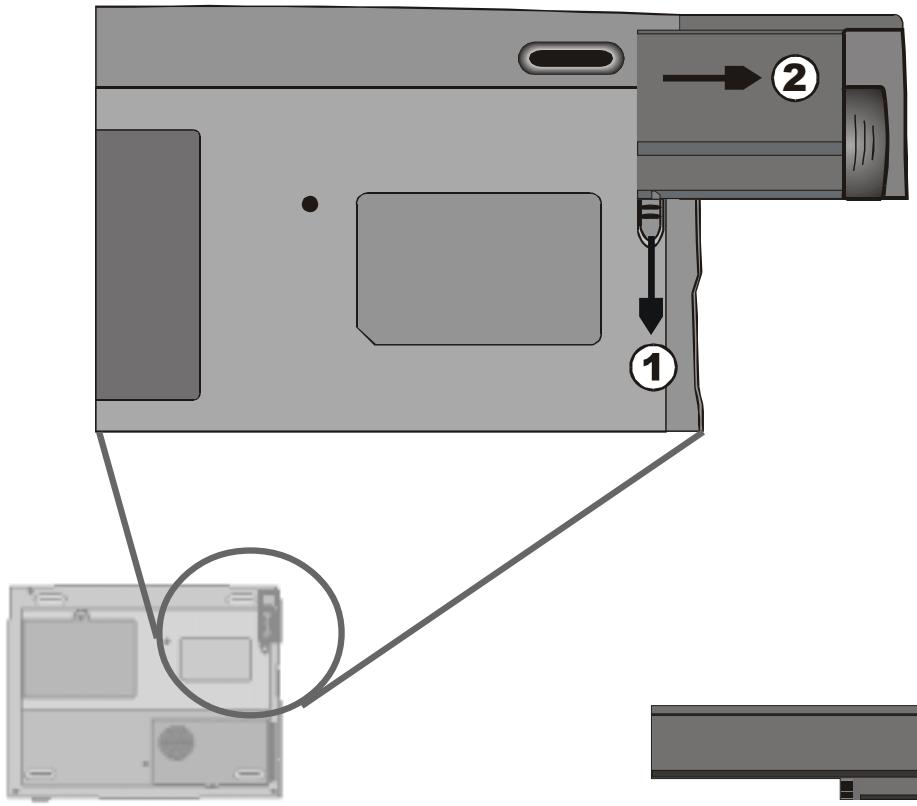
- Locate the battery latches. Slide the locked latch toward direcrion 1 shown by the arrow in the following figure and hold.
- Continue holding the latches in the releasing position, and pull out the battery's module hard case toward direction 2.
- Lift the battery pack out of the battery compartment as the right diagram.
To Install the Battery Pack:
- Position the notebook rear-side up on a flat and secured surface.
- Sliding the latch in the releasing position and hold.
- Carefully Insert the battery pack into the battery compartment of the unit until it is even with the edge of the notebook.
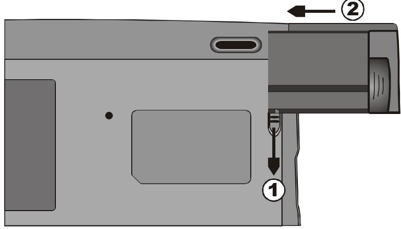
- Release the latch to lock.
Charging the Battery and Charging Time
To charge the battery, while the battery pack is in the notebook, plug the AC adapter into the notebook and an electrical outlet.
The charging time is approximately 2-3 hours when the notebook is turned off and approximately 3-5 hours when the notebook is turned on.
Note:
Be sure to reserve adequate time for charging before travelling.
If your notebook is plug into an AC outlet, the battery will still be trickle-charged even when the notebook is in operation. Charging an empty battery pack in the trickle-charge mode will take about 3-5 hours to attain full charge.
When the battery is fully charged, the battery charge indicator LED emits red light intermittently.
Checking the Battery Level
You can check the remaining battery power in the Windows battery status indicator, which is located at the lower right-hand corner of the task bar. The accuracy is within + / - 5 - 7% .
Alternatively, you can access the power meter by clicking the Power Management icon in the Windows Control Panel.
Prolonging the Battery's Life and Usage Cycles
There are ways you can do to prolong the use of battery.
Use the AC adapter wherever AC wall outlet is available. This will ensure uninterrupted computing.
Purchase the optional second battery pack.
Store the battery pack in room temperature. Higher temperature tends to deplete the battery's power faster.
Make good use of the power management function. Save To Disk saves the most energy by storing current system contents in a hard disk space reserved for this function.
- Disable the parallel and serial ports if no devices are attached to these ports. See section 2 for details of how this is done.
Even when PC card is not operating, it still draws a small amount of power. Eject the PC card from the card slot when not in use.
The life expectancy of the battery is approximately 500 recharges.
See the notices section in the beginning of the user manual on how to care for the battery pack.
Note:
Read Section
Protecting Your
Notebook in the
beginning of this
manual for tips
about how to
maintain the
battery pack.
Using Power Management
The system uses the following methods to management the power usage of various hardware subsystems.
Note:
When running on battery, try to refrain from opening too many applications at once.
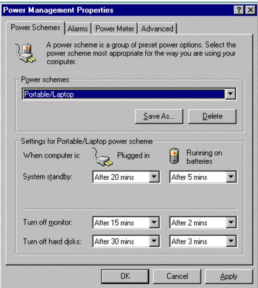
Windows offers two types of power management utility: the Advanced Power Management (APM) or Advanced Configuration Power Interface (ACPI, Windows98 only). In the Windows Power Management Properties (Start > Settings > Control Panel > Power Management) dialogue boxes, you may enter time-out values for monitor and hard disk drive. Windows power manager saves power by turning off hard drive after 1 minute of inactivities, for example. Consult Windows manual for additional details on Windows power management features.
Suspend Mode
When the battery power reaches critical low (at 3% remaining), the system can be set to enter either one of the two suspend modes:
Suspend
In Suspend mode, only few hardware devices, such as display panel and hard disk, are turned off to conserve energy. The other devices are put into low-power states.
Note:
To learn to adjust the parameters in the BIOS Power Management, go to Section 2 BIOS Setup.
Save To Disk
In this mode, all system data are saved in the hard disk before powering down. When this mode is activated, you will see 3 graphic meters indicating the progress of saving data to the disks. Once the meters reach 100% , the system is completely shut down. No power is drawn from the battery module under this mode. Therefore, it saves the most energy.
However, depending on how much RAM that have been installed on your notebook, the amount of time the system requires to restore all its previous contents can range from 15 to 30 seconds. In order to use the Save To Disk feature, a hard disk partition is required to store the system content. See the next few pages for instructions on how to create a Save To Disk partition/file.
Note:
If your Windows98 is operating on ACPI mode, you may define how the power/suspend button functions. Click on the Power Management icon in the Control Panel or consult Windows98 manual for more information.
Note:
If your Windows98 is operating on ACPI mode, you may define how the system functions when the LCD lid is closed. Click on the Power Management icon in the Control Panel or consult Windows98 manual for more information.
The Suspend Button
This notebook adapts the 'one-button' design, meaning that both the power on/off and system suspend functions are sharing the same physical button. The Power On/Off button also doubles as the Suspend button. You may also active suspend function using the Fn+F1 hot key combination.
Press the suspend/power button or hit any keys to wake the system from the power-on Suspend mode. However, if your notebook is in the Save-to-Disk mode, you must press the power/ suspend button to enable the resume event.
The LCD Panel Switch
There is a small mechanical switch near the edge of the LCD panel. Closing and opening the LCD panel activates the switch. This switch acts similar to the suspend button. If the suspend mode is set to Suspend, closing the LCD panel begins the Suspend cycle.
Opening the LCD panel or pressing the suspend button wakes the system from the power-on Suspend mode.
Power Consumption of the LCD Display
Your notebook comes with a TFT (active matrix) LCD display. The display is one of the hardware subsystems that tends to consume a lot of power. Whenever possible, you should turn down the display brightness to a bearable level to conserve energy. Turning down the brightness tends to prolong the working life of the back-light lamp in the display.
To decrease the LCD brightness level, press Fn+ F8.
To turn off the LCD display, use hotkey Fn+F4.
Note:
Do not install or remove the memory module when the system is in the Save To Disk suspend mode. Restart the notebook and power down before attempting to change the memory configuration.

Warning:
Running the PHDISK.EXE program will corrupt the data in the HDD. Therefore, reinstalling the software will be necessary.
Creating the Save To Disk Partition (or File)
The hard drive has a default Save To Disk partition. For example, the maximum system memory allowed is 160 MB; 16 MB is reserved for contents of the video chip and other microcontrollers. Therefore, in order to use this suspend feature under maximum system memory, you would need to increase the Save To Disk partition to 166MB.
If you want to resize the default Save To Disk partition, you will need to run the following utility program. However, executing the HDPREP.EXE program will destroy the data in your hard disk drive! You will need to re-install the operating system and application programs afterwards.
To resize or create the Save To Disk partition, do the following:
- Boot up your notebook to DOS.
- In the Factory CD-ROM (or diskette) locate a utility program called HDPREP.EXE.
- Type HDPREP at the DOS prompt and press Enter.
You will need to reformat the hard drive (the DOS partition) and re-install O/S and application programs.
If you are using DOS, Windows 3.x, or Windows 95 (FAT16), you may create Save To Disk file instead of partition. In this case, you do not need to reformat the hard disk and re-install O/S. To create the a Save To Disk file, follow the above procedure and enter PHDISK /create /file in step 3.
About Windows 98 Power Management Feature
Note:
Consult Windows98 user guide for more information on how to use the power management functions.
Note:
The notebook's BIOS supports Windows APM and ACPI modes. The illustration on the right shows the Windows98 legacy APM dialogue.Consult Windows98 manual on how to enable Windows ACPI mode.
In addition to the notebook's built-in power management utility, Windows 98 also offers a similar power management feature. To access this feature, go to [My Computer > Control Panel] and double-click on the Power Management icon.
The Windows power management allows you to enter time-out values for the display and hard disk. You can also have your notebook automatically enter a standby mode or shut itself down in the envent of low or critical battery power. For more information on the power saving features, consult Windows on-line help or manual.
SECTION 4
UPGRADING YOUR NOTEBOOK
In this section, you will learn how to upgrade the memory and hardware capacity.
Upgrading the Hard Disk Drive
Note:
Certain models that come with the IBM-brand hard drive emit a clattering sound when it is being rattled. This is a normal condition.
Replacing the original drive with one of larger capacity can increase the hard drive capacity of your notebook. The notebook uses a 9.5 mm (hight), 2.5-inch Enhanced IDE, Ultra DMA, or ATA-66 type hard disk.
Be sure to make a backup copy of all your data before attempting this operation.

Warning: Hard drive upgrade in this notebook is a delicate process. Please observe the following instructions carefully or have a qualified technician install it for you. Damages due to mishandling of this procedure is NOT covered by the manufacture's warranty.

Warning: Apply care when handling the hard disk.
Do not drop or applay any shock.
Do not press on the cover.
- Do not touch the connector with your fingertips.
Mishandling of the hard drive can result in permanent loss of data. Make a backup copy of the drive's content before you remove it.
Expanding the Hard Disk Drive
To replace the hard disk drive, do the following:
- Turn OFF the computer. Unhook the AC cord and all cables/devices attached to the notebook.
- Place your hand on a large metal object momentarily to discharge any static electricity.
- Locate the hard disk drive module on the bottom of the notebook.
- Release the fixing screw-A locked the HDD bay cover.
- Remove the HDD bay cover as the shown diagram.
- Now the mental tray protected HDD module and the fixing screws, B and C, reveal.
- Release the two fixing screws, B and C, securing the mental HDD tray and HDD module.
- Release the two fixing screws, D and E, securing the mental HDD tray and the unite.
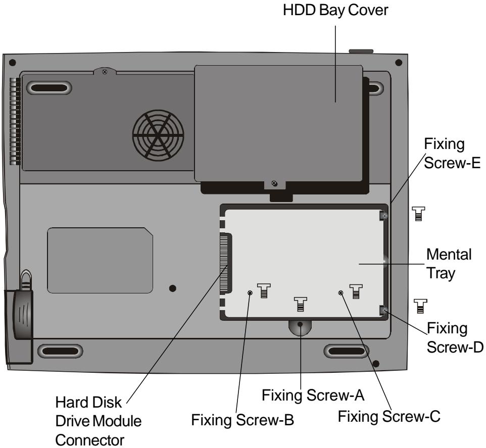
- Lift up the mental HDD tray 'til an angle of approximately 30 degrees and pull it up as the following illustration.
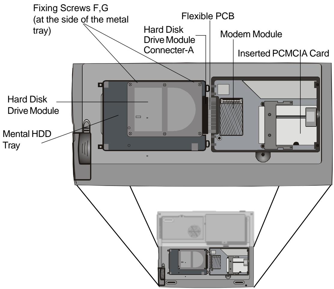
Illustration 4-1
- Note the orientation of the HDD module connector-A and carefully remove it from the hard disk drive. (Refer to the illustration < 4 - 2> shawn as next page)
- Locate and remove the rest 2 fixing screws, F and G, securing the metal HDD tray and HDD.
- Remove the mental HDD tray from the HDD Module. Note the green PC board of the hard disk drive is facing down.
- Now you may place the new drive unit on the mental tray and replace the fixing screws, B, C, F and G.
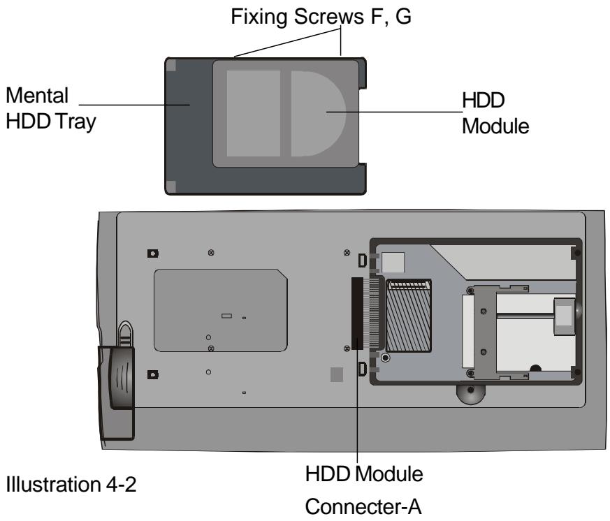
- Reinstall the connector-A on the new drive unit. Be sure the module makes a firm connection to the base connector.
- Carefully put the mental HDD tray back to the drive bay.
- Replace the fixing screws, D and E.
- Replace the HDD Bay cover.
- Turn the notebook right-side up, and power it on.
You have now completed the hard drive upgrade.
Once a new hard drive is installed, you need to reformat the disk and re-install the operating system and applications. If you would like to have the Save To Disk suspend function, it is recommended that you re-create the Save To Disk partition BEFORE reformatting the HDD because executing the PHDISK utility program will destroy the data on the hard drive and requires you to re-install all software. Go to Creating Save To Disk Partition, the end of Section 3, to figure out how this is done.
Upgrading the System Memory
Many applications will generally run faster when the notebook's memory capacity is increased. The notebook provides one expansion socket, located underneath the keyboard, for the memory upgrade. You can increase the amount of memory by adding a dual inline memory module (commonly known as DIMM.) The DIMM can be 16MB, 32MB, 64MB, 128MB or 256MB in capacity. The DIMM is of type Synchronous DRAM, has 144 pins and runs on 3.3V. The speed of the DIMM may be 70ns or 60ns (the smaller number the faster.)

Warning: Memory upgrade in this notebook is a delicate process. Please observe the following instructions carefully or have a qualified technician install it for you. Damages due to mishandling of this procedure is NOT covered by the manufacture's warranty.
Warning: Changing memory while your computer is in suspend or power-saving mode may cause permanent damage to the notebook. Make sure you turn off the power and unplug the AC cord before proceeding with a memory upgrade.

Expanding The DIMM Module In The Original Socket
To expand the DIMM, do the following:
Warning:
To avoid
damaging the DIMM, do not
touch its metal
contact edge to
avoid the electro-
static damage
from static
electricity.
- Power OFF the notebook. Unplug the AC cord and all cables/devices attached to the notebook.
- Place your hand on a large metal object momentarily to discharge any static electricity.
- Place the notebook on a flat surface and fully open the LCD lid.
- Find the keyboard latches A, B and C near the bottom edge of the keyboard referring to the figure as below. The latch is spring-loaded. It will retract when pressed and revert back to its original position when released.
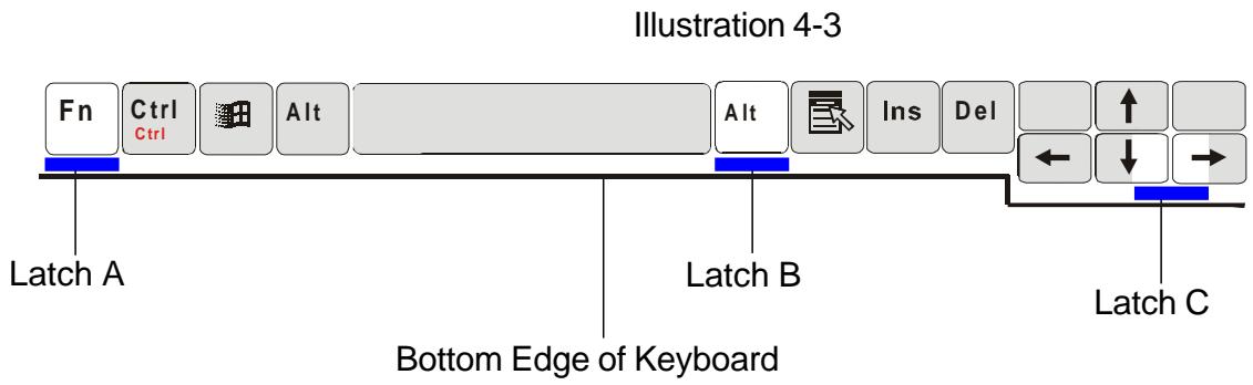
- Using a small blade to press the latch A downward. The keyboard should pop up slightly over the latch. If the keyboard does not pop up, try to gently lift it up just over the latch. Repeat the step for the other keyboard latches.
- Carefully lift up the bottom edge of the keyboard and the following is revealed.
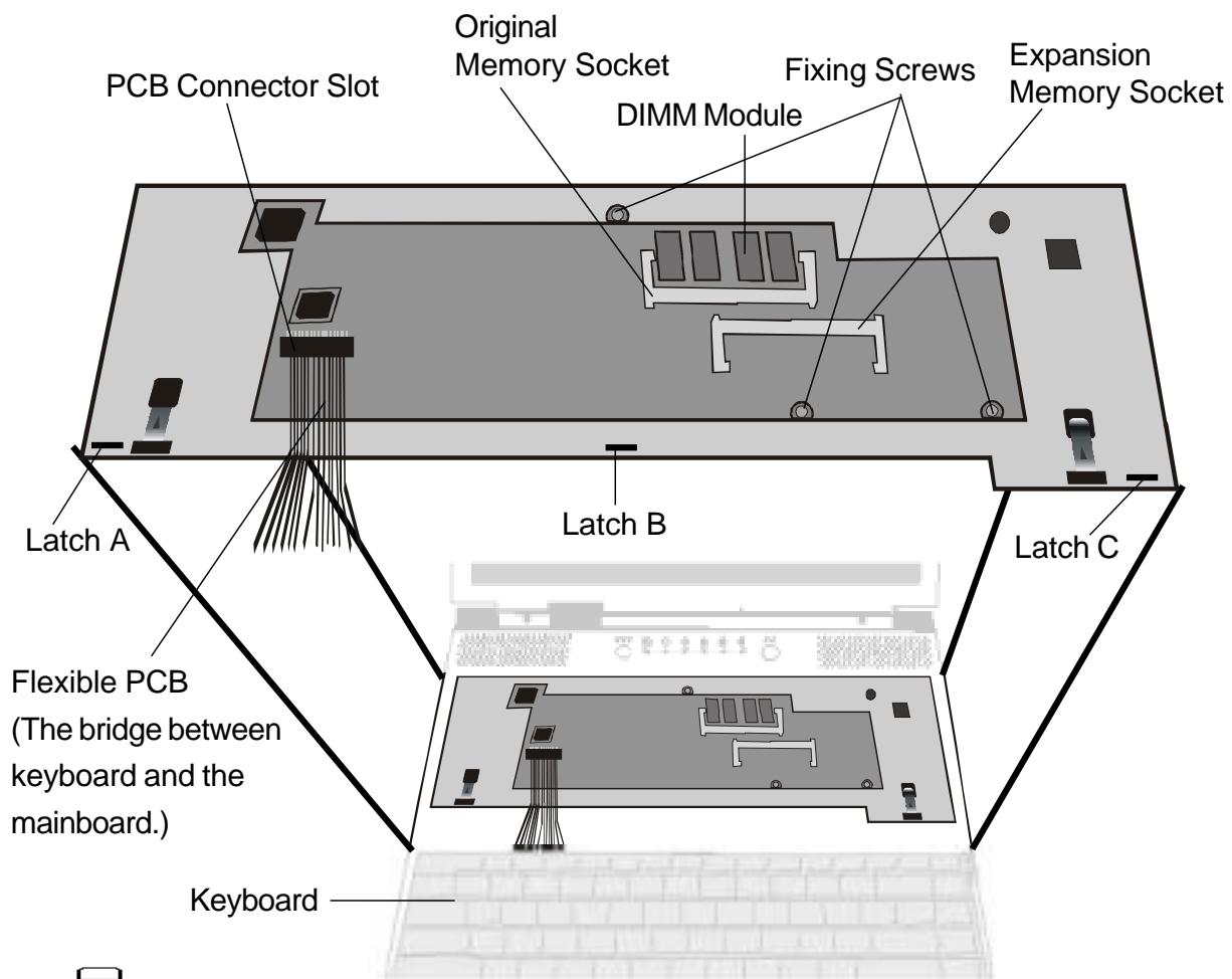
Illustration 4-4
Note:
Your notebook has been tested with a wide range of DIMM on the market. However, not all memory modules are compatible. Check with your notebook vendor for a list of compatible DIMM for your notebook.
- The memory socket is now revealed as the shown illustration 4-4.
- Press out on the latches located on both edges of the socket at the same time. The DIMM should pop up to an angle of 30 degree.
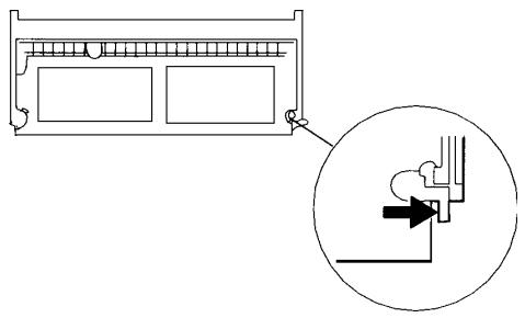
Note: Notice the notches on the DIMM. The notches should fit nicely with the socket.
- Pull the DIMM module out of the memory socket. Be sure to reserve the DIMM for the future use.
- Install the DIMM module into the memory socket. The DIMM will only fit in one orientation. Slide the DIMM at an angle of approximately 30 degrees into the empty memory socket. Then press it firmly so that the contact edge is driven into the receiving socket.
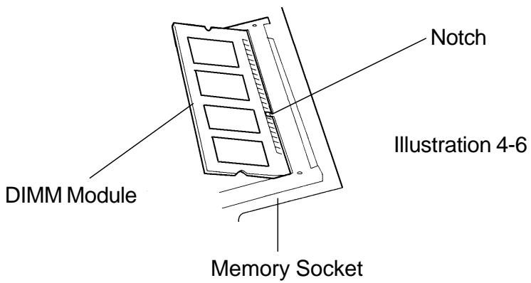
- Pivot the DIMM until the latches on both sides of the socket snap into place. At the time, you will feel a click.
- Put the keyboard back to its original face-up position. Be aware of the flexible PCB connected to the keyboard. The keyboard should now be locked by the spring-loaded latches.
You have just completed the memory upgrade.
Installing the DIMM Module In The Expansion Socket
To remove the memory module, do the following:
- Follow steps 1~7 in the above section, Installing the DIMM Module In The Memory Socket.
- Hold the extended memory module at a 30-degree angle and slide it into the empty momery socket.
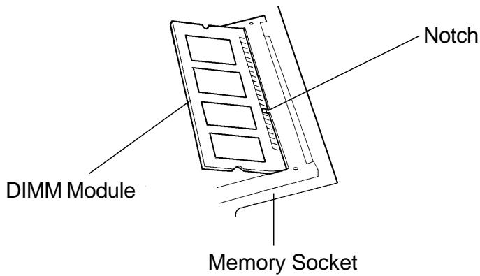
- Align the small notch in the module with the socket on the connector and gently push it in and down until it clicks in place.
- Pivot the DIMM until the latches on both sides of the socket snap into place. At the time, you will feel a click.
- Put the keyboard back to its original face-up position. Be aware of the flexible PCB connected to the keyboard. The keyboard should now be locked by the spring-loaded latches.
You have just completed the memory upgrade.
Removing the DIMM Module In The Expansion Socket
To remove the memory module, do the following:
- Follow steps 1~7 in the above section, Installing the DIMM Module In The Memory Socket.
- Press out on the latches located on both edges of the expansion socket at the same time. The DIMM should pop up to an angle of 30 degree.
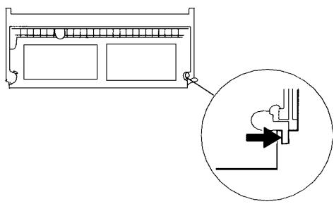
Illustration 4-7
- Remove the DIMM from the expansion socket. Be sure to save the DIMM for future use.
- Put the keyboard back to its original face-up position. Be aware of the flexible PCB connected to the keyboard. The keyboard should now be locked by the spring-loaded latches.
- Power on the notebook and when it starts up note if the memory count has decreased to the original memory capacity.
You have completed the removal of the DIMM.
SECTION 5
TROUBLE SHOOTING
In this section, you will learn how to solve common hardware and software problems.
Your notebook has been fully tested and complies with the system specifications before shipping. However, incorrect operations and/or mishandling during shipment may cause problems.
This section provides a reference for identifying and correcting common hardware and software problems that you may encounter.
When you encounter a problem, you should first try to go through the recommendations in this section. Instead of returning the notebook and waiting for repair, you may easily solve the problems by considering the following problems and possible solutions. If the error continues, contact your reseller for service information.
Before taking further actions, consider the following suggestions:
- Check to see if the problem persists when all the external devices are removed.
Check to see that the green light indicator on the AC adapter is lit. - Check to see the power cord is properly plugged to the wall outlet and to the notebook.
Check to see the power indicator of the notebook is on.
Check the brightness control on the keyboard if the LCD display appears dim. - Check to see if your keyboard is operational by pressing and holding any key. An audible beep indicates the keyboard is functioning correctly.
-
Check for any incorrect or loose cable connections. Make sure the latches on the connectors latch securely on to the receptor end.
-
Be sure you have not performed an incorrect setting on the hardware devices in the BIOS Setup utility. A faulty setting may cause the system to misbehave. If you are not sure of the changes you made, try to restore all the settings to factory defaults.
- Be sure all the device drivers are installed properly. For example, without the audio driver properly installed, the speakers and microphone will not work.
If external devices such as USB camera, scanner, SCSI card do not function correctly when connected to the system, it is usually the device's own problem. Consult the device's manufacturer first.
Some software programs, which have not gone through rigorous coding and testing, may cause problems during your routine use. Consult the software vendor for problem solving.
Not all peripheral are plug-and-play capable. You need to restart the system with these devices powered up and connected first.
Audio Problems
No speaker output -
- Software volume control is turned down in Microsoft Sound System. Double-click the speaker icon on the lower right corner of the taskbar to see if the speaker has been muted.
Press Fn+F5 Up increase the volume.
Most audio problems are software-related. If your notebook worked before, chances are software may have been set incorrectly. - Go to [Start > Settings > Control Panel] and double-click the Multimedia icon. In the Audio page, make sure that SiS Audio Wave is the preferred playback device.
Sound can not be recorded -
Double-click the speaker icon on the lower right corner of the taskbar to see if the microphone has been muted.
1. Click Options and select Properties.
2. Select Recording and click the OK button.
3. After Click OK button, the recording volume control panel will pop up as shown.
- Go to [Start > Settings > Control Panel] and double-click the Multimedia icon. In the Audio page, make sure that SiS Audio Wave is the preferred playback device.
Hard Disk Problems
The hard disk drive does not spin -
If you had just performed a hard disk upgrade, make sure the hard drive connector is not loose and the hard disk drive is also correctly seated. Remove it and reinsert it firmly (feel it clicking into a place), and restart your PC. (Read Section 4 Upgrading Your Notebook for details.)
Check the hard disk indicator LED. When you access a file, the LED lamp should light up momentarily.
The new HDD may be defective.
If your notebook has been subjected to static electricity or physical shock, you may need to reinstall the operating system.
The hard drive is making abnormal whining noises -
You should back up your files as soon as possible.
Make sure the source of noise if indeed from the hard drive and not the fan or other devices.
The hard disk drive has reached its capacity -
- Delete backup files or move them to an alternative storage medium (floppy disk, optical disk, etc.). Many programs save backup files. You can delete backup files from the hard disk to create more space for new work.
- Archive files or programs that you had no longer used by moving them to an alternative storage medium (floppy disk, optical disk, etc.) or uninstall programs that no longer use.
Many browsers store files in the hard drive as a cache to speed up the performance. Check the program's Online Help for instructions on decreasing the cache size. - Empty the Recycle Bin to create more disk space. When you delete files, Windows 95 copies them to the Recycle Bin.
The hard disk performs pretty slow -
If you have been using the unit for a period, the files may be fragmented. Go to [Start > Programs > Accessories > System Tools > Disk Defragmenter] to perform a disk defragment. This operation may take a while.
The files are corrupted -
- Run the ScanDisk surface scan to check the platter. (This function is available in Windows 95/98, but not Windows NT). Go to [Start > Programs > Accessories > System Tools > ScanDisk] to perform a disk surface scan. This operation may take a while.
CD-ROM Problems
The CD-ROM drive does not work -
Try rebooting the system.
The CD-ROM driver is not loaded. Go to [Start > Settings > Control Panel > System] and in the Device Manager see if the CD-ROM driver is enabled. If you see a red cross or yellow mark, there may have been a resource conflict. See Windows on-line help or manual for more information.
After you have inserted a CD-ROM disk, it may take a moment before you can access its content.
The CD-ROM drive dose not read any CDs -
The CD may not be properly seated in the tray. Have CD on the tray and press the CD firmly onto the spindle, also make the retaining clips held the CD in place.
Note:
There are two kinds of types of CD-ROM might be installed as shipped. One is electrical and the other is mechanical. Basically, the mobile computer is equipped to electrical CD-ROM. With this device, you can do the CD-ROM ejection only if the system is on. As for bundling the mechanical type, the ejection button works all the time, even the system is powered off. Please be also noted, the mechanical one is not available to eject the CD-Disk by performing Fn key under the running Windows 98 operating system.
Floppy Disk Problems
The floppy disk does not work properly
Check the color indicator LED for FDD. When you access a file, the LED lamp should light up momentarily.
The floppy diskette may be damaged. Try a different diskette to see if the problem persists.
Check if the disk is fully inserted into the floppy drive.
The floppy drive does not save -
- Check if the tab of the floppy disk is on the write-protect position.
Have the disk formatted.
If the disk capacity had been reached, use another disk or remove the existing files to make room for the svaing file.
The diskette does not eject from the drive -
The metal cover on the diskette might be bent. Contact your local dealer for technical support.
A label may be became detached and is blocking the ejection of the disk. Visually inspect slot to see if any obstruction occurred by the label. Contact your local dealer for technical support.
Display Problems
The display panel is blank when the system is turned on -
Make sure the notebook is not in the Suspend or Save To Disk modes. The display is turned off to conserve energy in these modes.
Press Fn+F7 to increase the screen brightness.
Press Fn+F4 to make sure the notebook is not in the CRT-output only mode.
The screen is difficult to read -
Press Fn+F7 to increase the screen brightness.
The display resolution should be set to 1024x768 for optimal viewing.
- Go to [Start > Settings > Control Panel] and double-click on the Display icon.
- Under the Settings page, click the Advanced icon.
- Under the Dispaly Modes page to set the resolution to 1024x768 and choose at least 256 colors.
Keyboard and Pointing Device (Mouse) Problems
The built-in keyboard accepts no input -
This notebook is designed to use only one keyboard at once time. If you had already connected an external keyboard to the system, the built-in keyboard won't work. Disconnect the external keyboard and try to reboot the notebook.
If there is no external keyboard connected, still restart the system again.
The external PS/2 or serial mouse does not work -
Some external mouse comes with special function (such as 3 buttons). In that case you may need to disable the built-in touch pad. Go to Section 2 BIOS Setup for instructions on how to disable the internal pointing device.
A special mouse may require a unique driver. Make sure the driver is properly installed.
A special external mouse with the thumb-wheel (scroll-wheel) is not plug-and-playable. In order to enable this device, you need to have the mouse connected to the P/S2 port before powering up to Windows. Also, you may need to install the driver, which is specifically designed for this special type of mouse, to make it work.
The built-in touch pad does not work -
Make sure the internal PS/2 port (pointing device) is enabled (or set to Auto Detect) in the BIOS Setup. Go to Section 2 BIOS Setup for details on how to enable the PS/2 mouse.
The built-in touch pad performs eratically -
Make sure there is no excess perspiration or humidity on your hand which might make the pointing device short. Keep the surface of the touch pad clean and dry.
- Do not rest your hand or wrist on the surface of the touch pad while typing or using the touch pad. Since the pointing device can sense any movement of figertip, to rest your hand on the surface would lead to the sluggish and slow-moving performance.
The characters on the screen repeat while I type.
You may be holding the keys down for long while you're typing.
- Keep the keyboard clean. Dust and dirt under the keys could cause them to stick.
- Configure the keyboard to wait longer before the auto repeat feature starts. To adjust this feature, Go to [Start > Settings > Control Panel], and double-click on the Keyboard icon. A dialogue box shows up with the adjustable settings for the keyboard.
CMOS Problem
A message “CMOS Checksum Failure” displays during the booting process -
If the message "CMOS Checksum Failure" appears during the booting procedure, it might indicate the shortage or the run-down condition of the small CMOS (Complementary Metal-Oxide Semiconductor) battery. If so, you need to renew the CMOS battery. In the life cycle test, it illuminates one to one and half years as lasting operation. Since most users don't operate the system continually in reality, the Ni-Cd CMOS battery might run out of power after 3 or 5-year usage. In another word, the CMOS battery replacement needs to be done after a long operating period.
For more detail information or technical support, please contact your local dealer or distributor.
Infrared Problems
The infrared communication port does not work -
If you had just completed Windows 98 setup process, you need to update the loaded FIR driver. The steps listed below will guide you through the process of renewing the IrDA driver.
- Go to [Start > Settings > Control Panel > System ], click the Device Manager tab.
- In the Device Manager, double-click the Network Adapters, select IrDA 3.0 Fast Infrared Port under Network Adapters item and press Property button.
- In the Network Properties page, click the Driver tab and press Update Driver button.
- In the Update Driver Wizard window, click Next.
- Select "Display a list of all the driver in a specific location" and click Next.
- In the Select Device windows, select "Show all devices", "National Semiconductor" as manufacturer and "NSC-PC87338 Fast Infrared Prot" as model. (If you can not find National Semiconductor in the manufacturer column, please click Have Disk button and insert the factory CD-ROM and input the path which the driver located.)
- Then, a updating driver warning dialog pops up, and click OK.
- Click Next button and Finish button in the following Update Driver Wizard windows.
- Restart the computer.
- Go to [Start > Settings > Control Panel > Network ], select "NSC-PC87338 Fast Infrared Port" and press the Proprety button.
- In the NSC-PC87338 Fast Infrared Port Properties page, click the Advanced tab. And then, select "Infrared Transceiver A" and set "HP HSDL-2300" in the Value column. Still, a warning dialog shows up and click "OK".
- Click OK button and Yes button in the following screens.
- Reboot the system.
Windows NT 4.0 does not support infrared devices.
Remove any objects that sit between the communicating path.
Make sure the communicating devices are not more than 1 meter apart and are aligned in a straight-line fashion.
Make sure that IR device is enabled in the Control Panel. If the infrared icon at the lower right corner of the task bar has a red 'x symbol, it is being disabled. Click on the icon and in the Option page check off the Infrared Communication item.
Check the infrared setting in BIOS Setup utility. Go to Section 2 BIOS Setup to find out how this is done. If you are using Windows 95 and have enabled Fast IR option in the BIOS Setup, you must load the vendor-specific IR driver manually for it to work (Windows 95 comes with standard IrDA driver only.)
Memory Problems
The POST does not show an increased memory capacity when you have already installed additional memory -
Certain brands of memory module may not be compatible with your system. You should ask your vendor for a list of compatible makers of the DIMM.
The memory module may not be installed properly. Go back to Section 4 Upgrating Your Notebook to review the details of this operation.
The memory module may be defective.
The O/S issues an insufficient memory error message during operation -
This is often a software or Windows-related problem.
- Close the application programs you're not using and restart the system.
- Otherwise, you have to install additional memory module. For instructions, go to Section 4 Upgrading Your Notebook.
Modem Problems
The built-in modem does not respond -
Make sure the modem driver is loaded properly. Go to [Start > Settings > Control Panel > Modem] and make sure HAMR 5600 Voice Modem is listed in the Modems Property page. Otherwise, click the Add button to add the modem drive, which is located in the factory CD-ROM (or floppy diskette).
- Go to [Start > Settings > Control Panel > System] and in the Device Manager page check for possible resource or driver conflict. See Windows on-line help or manual for how to handle such problems.
Make sure the phone line the notebook connected to is valid.
The fax/modem disconnects during transmission -
■ Be sure to disable the Call Waiting.
- Excessive line noise might cause the connection to be dropped and maybe you had connected to a noisy line. To check this, put the regular phone handset on the line and placing a phone call. If you do hear an amount of abnormal noise, try to make the modem connection with a different line or contact your local telephony service company.
Make sure the correct setting of the communications software. Check with the manaul of the programs to customize the modem.
The fax/modem doesn't transmit properly -
Make sure the RJ-11 cable (the one that goes from the modem to the telephone line) is firmly connected to the modem's RJ-11 jack and the telephone line socket.
- Check the serial port settings. Make sure the hardware and software are referring to the same COM port.
- Check the communications parameters (baud rate, parity, data length and stop bits) specified in the communications program.
The connecting system, such as the central side equipment, might be busy or offline. Try to make another transmission test to other sytem.
- Be sure the line has a dial tone.
Network Adapter Problems
The Ethernet adapter does not work –
- Go to [Start > Settings > Control Panel] and double click the System icon. Select the Device Manager tab from the System Properties. Double-click on Network Adapters and check if SiS 0900 PCI Fast Ethernet Adapter appears as one of the adapters. If it does not exist, Windows has not detected the SiS adapter or the device driver has not been installed. If there is a yellow mark or red cross on the SiS network adapter, there may be a device or resource conflict. Consult Windows manual on how to solve this problem.
Make sure the physical connections on both ends of the cable are good.
The hub or concentrator may not be working properly. Check to see if other workstations connected to the same hub or concentrator are working.
Repeat the undock and then dock sequence.
Try restarting Windows with the port replicator already connected to the network.
The Ethernet adapter does not appear to operate in the 100Mbps transmission mode –
Make sure the hub you are using supports 100Mbps operation.
Make sure that your RJ-45 cable meets the 100Base-TX requirements.
Make sure the Ethernet cable is connected to the hub's socket that supports 100Base-TX mode. The hub may have both 100Base-TX and 100Base-T sockets.
PC Card (PCMCIA) Problems
PC Cards do not function-
Make sure you have properly installed the driver for the card.
■ Consult the card's manual or contact the vendor for troubleshooting.
The PC card can not be recognized-
Windows NT4.0 does not support PCMCIA (PC Card) function. You may need an external program for this.
Make sure the card is fully inserted; the outer end of the card should be even with the edge of the notebook.
Remove and insert the PC card again.
Make sure there is no IRQ conflict with the card. See Windows on-line help for solving IRQ conflicts.
Reboot the notebook and see if the problem persists.
The card may be defective. Try the card on another system, if possible.
Windows crashes or freezes when you remove the PC card-
Make sure you have
Performance Problems
The notebook becomes hot -
In a 35° C environment, the notebook's bottom case is expected to reach 50 degrees.
Make sure the air vents are not blocked.
If the fan does not seem to be working at high temperature (50 degrees Celsius and up), contact the service center.
Certain programs that are processor-intensive may increase the notebook temperature to a degree where the notebook automatically slows down its CPU clock to protect itself from thermal damage.
The program appears stopped or runs very slowly -
Press CTRL+ALT+DEL to see if an application is still responding.
Restart the notebook.
This may be normal for Windows when it is processing other CPU-intensive programs in the background.
- You may be running too many applications. Try to close some applications or increase system memory for higher performance.
You may have selected Maximum Power Savings or Idle Mode. These power saving options slow down the CPU to conserve power. See Section 2 BIOS Setup and Section 3 Battery Power / Power Management for more information.
Power, Start, and Battery Problems
The notebook powers down as soon as it is powered on -
Battery power may be extremely low. The circuitry prevents a complete power drain, which is not intended for Lithium Ion batteries. Use the adapter to charge it for several hours before trying again.
The notebook beeps intermittently -
When battery charge is critically low, an audible beep warns you. Press Fn+F3 to turn off the warning beep.
The battery life gets shorter and shorter -
The battery has a finite life of about 500 charge cycles. If your battery is over one or two years old, it may be time to have it replaced.
Try a higher power saving setting in the BIOS or in the Windows Power Management.
The battery does not charge -
Make sure the AC adapter is plugged into a valid power source.
Check to see if the green lamp on the adapter is lit when it is plugged in.
The battery charge indicator LED on the notebook should be lit when you plug in the AC adapter.
Make sure the battery module is fully inserted in its bay; make sure the battery latch is in locked position.
If the battery is operating at a very high temperature, it may not charge.
Printing Problems
The printer does not print -
Make sure the cable connection is secured and the printer is powered up.
■ Run the printer self test to investigate any problem of the hardware itself.
Check if the printer displays any error messages. A paper jam may have occurred.
Make sure you have already installed the printer driver.
- Most printer (using parallel or serial port) problems are software-related. Consult Windows on-line help or contact the printer vendor for assistance.
Try rebooting the system with the printer powered up and connected first.
The printer does not print what's on the screen -
The display information on the screen is different from what would print out and this happens in many software programs. Check if the preview function is in the taskbar and see if the working document shows exactly as it print. Contact the software provider for technical support.
If the printer print the extra and strange symbols, it is the result of the cache (garbage) in the printer momery buffer. Call off all the printer task and toggle off the printer switch to refresh the momery buffer. Then, trun the printer back online and print again.
Make sure you install the correct printer driver.
The printer does not respond to infrared communication -
See Infrared Problems listed elsewhere in this section.
Serial, Parallel, and USB Problems
The device that attached to the serial port is not working -
Make sure the cable is fully connected.
Maybe you have a broken cable or a wrong type cable, try replacing the cable.
- Check the device setting in the Windows Control Panel, [Start > Settings > Control Panel > System > Device Manager], and in the BIOS to be sure that the port is enabled. If the port is disabled, the system won't communicate with any external devices connected to the port.
Make sure the port is set properly to the correct value (COM1 or COM2) to activate the serial port. Check the device settings in the Windows Control Panel and in the BIOS. If it is set to another value and you have made no change to avoid the conflict with another device, set it to the correct COM port. (COM 1 usually is the default one.)
The serial-port devices may not be plug-and-play capable. Reboot the notebook with the devices powered up and connected first.
The Parallel Port does not work -
Make sure the cable is fully connected.
- Check the device settings in the Windows Control Panel and in the BIOS.
The parallel-port devices may not be plug-and-play capable. Reboot the notebook with the devices powered up and connected first.
The USB device does not work -
Windows NT 4.0 does not support USB protocols
Check the settings in the Windows Control Panel.
Make sure you have installed the necessary device drivers.
- Contact the vendor for additional support.
APPENDIX A
PRODUCT SPECIFICATION
Processor and Core Logic
-
Processor 400/433/466/500 MHz Intel Celeron processor. Socket Type, PIII FCPGA at 500/550MHz
-
L1 Cache 32KB (16KB for Code Instruction, 16KB for Data) on-die.
- L2 Cache 128KB Cache on-die.
- Core logic SiS chipset with graphic, audio and modem controller integrated
- Bus 66 MHz Front Side Bus (100 MHz ready), PCI / AGP. Architecture
System Memory
- Memory Type Synchronous DRAM system memory.
- Default 32MB, 3.3-Volt 64-bit bus
- Memory Two 144-pin SO-DIMM socket accept 32MB, 64MB, 128MB, or Expansion 256MB SDRAM modules in any combination for system memory expansion up to 512MB.
LCD
- Display Panel 14.1-inch XGA active-matrix TFT display or 13.0-inch DSTN XGA active-matrix (TFT) display supported resolution 1024x768 with up to 16M colors.
Graphics
- Graphic SiS 630 with integrated AGP bus 2D/3D graphics accelerator. Controller
- Graphics UltraAGP architecture graphics capability (similar to 4X AGP). Ability 3D Graphics Supported.
- Playback Direct DVD MPEG-2 and AC-3 Playback Supported. Motion Compression and IDCT Supported for DVD Playback.
- Dual Display Simultaneous LCD/External Monitor Supported.
- Dual Independent LCD and External Monitor Display Supported.
- Dual Application Capacity.
- Memory UMA architecture with 4/8/16/32 system memory sharable as Sharing display memory.
- Other
- Direct3D compatible. Features
- Zoomed Video support for PC Card slot.
- Fully DirectX 6.0 Compliant Graphics Engine.
- VESA DDC1, DDC2B & DDC 3.0 supported.
Storage Capacity
- Hard Disk 2.5-inch / 3-inch format (9.5mm height) removable drive with capacity of 1.6 6.4GB
- Diskette 3.5-inch format fixed module with accommodating 3 modes as Drive 720KB, 1.44MB, and 1.2MB.
Audio
- Audio SiS 630 with integrated audio controller Chipset
- Sound 64-voice Polyphony Wavetable Synthesizer.
Capability DirectSound 3D accelerator for IID, IAD and Doppler effects.
Full duplex, independent sample rate converter.
SoundBlaster Pro/16 compliant.
AC'97 V2.1 interface supported.
Full deplex and independent sample rate converter for audio recording and playback.
Modem
- Chipset SiS 630 with Modem Controller integrated.
- Transmission V.90 / K56flex for download data speed up to 56000bps. Speed V.34, V.17, V.29 transmission protocol.
LAN
- Network SiS 630 with integrated PCI Fast Ethernet function for 10Base-T Adapter and 100Base-TX network standards.
- PnP Function Windows 95 / 98 Plug and Play compatible
- Flow Control Automatic Jam and auto-negotiation for flow control.
- Speed Auto Negotiation and Parallel detection for automatic speed Selection selection (IEEE 802.3u).
- Other
- High performance 32-bit PCI bus master architecture with integrated DMA controller for low CPU and bus utilization.
- Remote Wake-up Scheme supported.
- Hot Insertion supported.
Other Standard Hardware
-CD-ROM 5.25-inch format (12.7mm height) fixed module with 24X speed.
- DVD ROM 5.25-inch format (12.7mm height) fixed module. (Optional)
- Keyboard 87-key touch-type QWERTY keyboard with embedded numeric Keypad.
- Pointing Device TouchPad with 2 buttons.
PC Card
- PCMCIA O2Micro OZ 6812 / 6912 controller with Zoomed Video Capability. Controller
- Features Single slot for TYPE II / III PC Cards with Card Bus 1.0 interface, having hot insertion and removal supported, enabling connection to peripherals as multimedia communications.
Ports
VGA Port One 15-pin CRT connector
- Audio Port One stereo line-out jack & One microphone-in jack
- Infrared Port One FIR LED
- Parallel Port One 25-hole parallel connector (ECP / EPP)
- Serial Port One 9-pin serial connector (16550A / FIFO)
- USB Port One USB connector
- PS/2 Port One 9-pin connector
- Modem Port One standard phone jack (RJ-11)
- LAN Port One standard network connector (RJ-45)
- Power Port One DC-in connector
Power
- Main Battery Ni-MH 10-cell, 48.0 Whrs (total capacity), 12.0V, 4000mAh. Li-Ion 8-cell, 47.4 Whrs (total capacity), 14.8V, 3200mAh.
- AC Adapter 100~240V, 50~60Hz, 20/60W.
- Recharge System OFF: 3~4 HR (100%)
System ON: 8~10 HR (100%) - Other
- Low Battery Warning Features
- Suspend / Resume capability
BIOS
- PnP Function AMI PnP BIOS
- Self Test Power On Self Test
- Auto Detection
DRAM auto-detection, auto-sizing L2 Cache auto-detection Hard disk type auto-detection - Power APM 1.2 (Advanced Power Management) & Management ACPI 1.0 (Advanced Configuration Power Interface)
- Security Two Level Password Protection
- Other 32bit access, Ultra DMA, PIO5 Mode support
Features Multi-boot capability
Operating System
- O/S Microsoft Windows 95 / 98 / 2000
Microsoft NT 4.0
Phsical Specification
Weight 256 (D) x 315 (W) x 39.5 (H) mm
- Environmental 6.5 lbs (with CD-ROM & FDD)
Limitations Operating Temperature: 5 to 35°C (41 to 95°F )
Operating Humidity: 20 to 90 percent RH (5 to 35°C )
Storage Temperature: -20 to 50°C (-4 to 122°F )
Note:
There are two kinds of types of CD-ROM might be installed as shipped. One is electrical and the other is mechanical. Basically, the mobile computer is equipped to an electrical CD-ROM. With this device, you can do the CD-ROM ejection only if the system is on. As for bundling the mechanical type, the ejection button works all the time, even the system is powered off. Please be also noted, the mechanical one is not available to eject the CD-Disk by performing Fn key under the running Windows 98 operating system.
Note: Product Specifications are subject to change without notice or obligation.
APPENDIX B
SPECIAL VGA FUNCTIONS
In this section, you will learn how to take advantage of the special DualView feature via the VGA controller.
The VGA controller (graphics processor) on your notebook is capable of DualView function. This unique display feature allows you to work efficiently when you have access to an external CRT monitor or RGB projector for a large audience presentation. With DualView, you can access separate Windows applications on the TFT display and on the CRT monitor simultaneously and independently.
If the VGA driver and SMI Control Panel program have not already installed on your notebook, use the following procedures to install them first.
Windows 98 Display Driver Installation / Update
To install/update the driver, do the following:
- Go to [Start > Settings > Control Panel] and double-click the Display icon.
- Click on the Settings tab in the Display Properties folder.
- Click on the Advanced button on the lower right-hand corner.
- Click on the Adapter tab.
- Click on the Change button.
- The Update Device Driver Wizard (if you are using Windows 98) should pop up.
- Click the Next button and insert the factory CD-ROM and point to the location which contains the VGA driver.
Using the DualView Function
With DualView function, you have gained twice as much desktop space without having to purchase additional graphics controller card.
DualView allows you to run different applications independently across two display device. (For example, the external CRT and notebook's LCD display).
Important:
Instructions to activate the DualView function:
- Right-click on the SiS icon located at the lower right-hand corner of the Windows task bar.

- Go to [Display Property > Display Setting], press Advanced button.
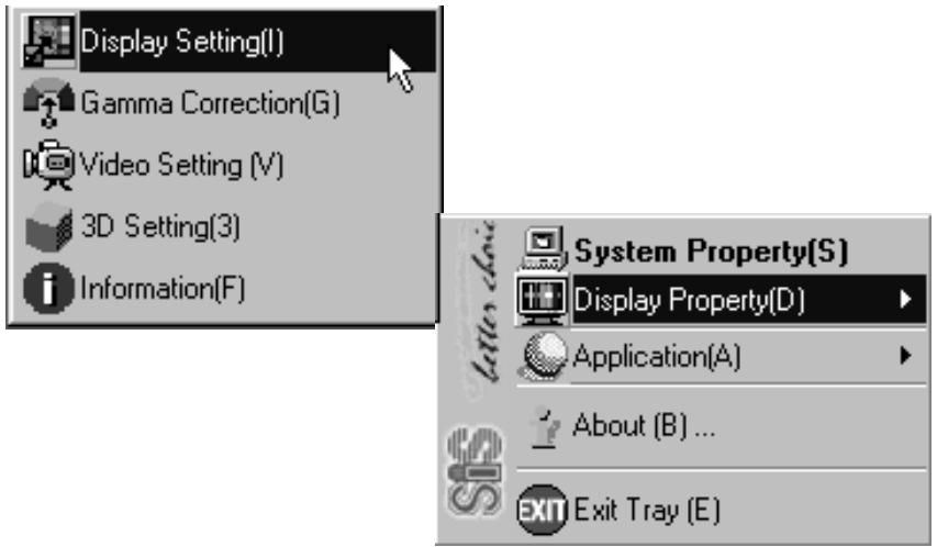
- Or alternatively, you may Go to [Start > Settings > Control Panel > Display] and click on the Settings tab. Click Advanced button and select the Display Modes tab. After the process, you should see the following dialogue box.
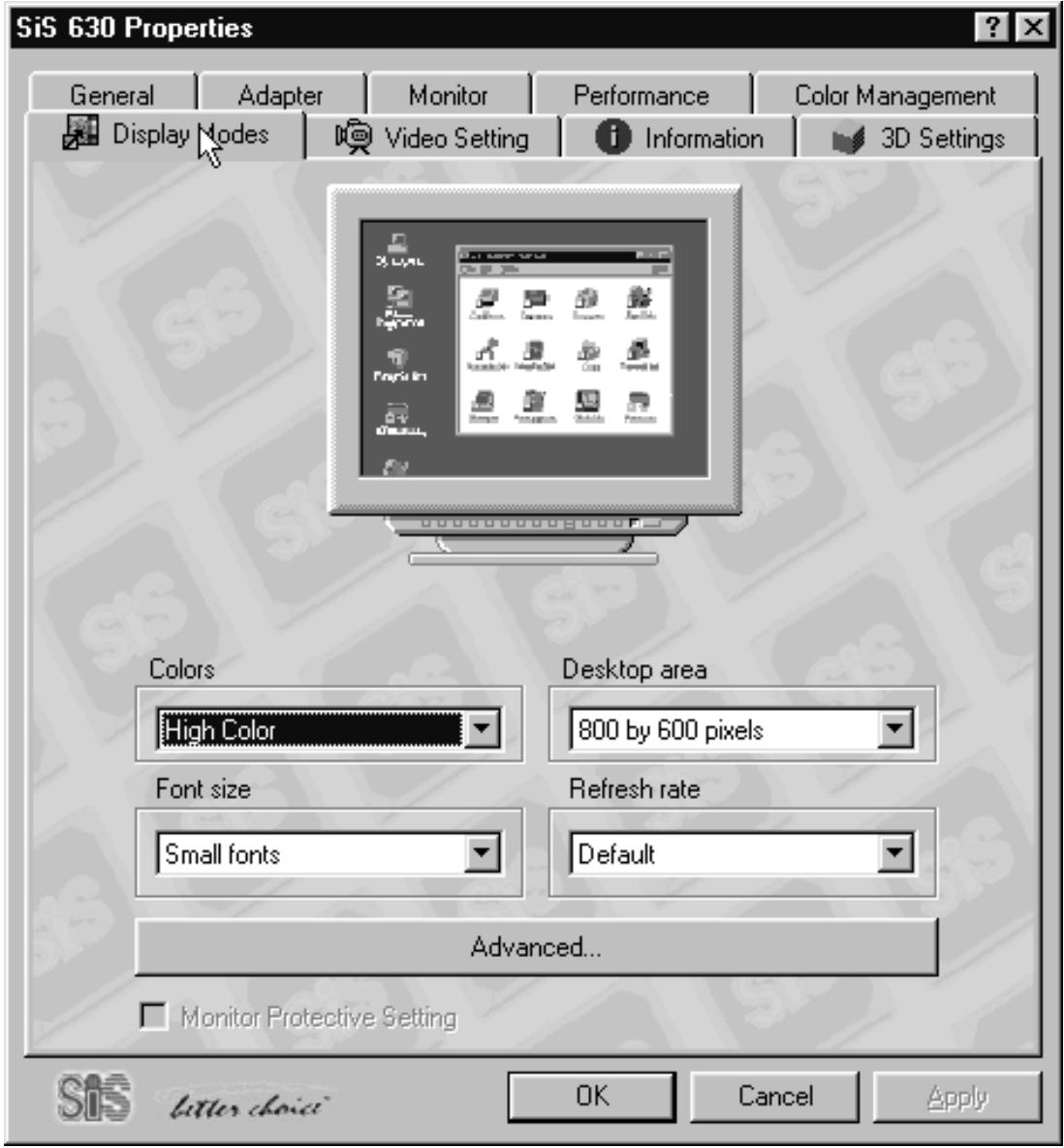
- Click on Advanced button.
- After clicking the Advanced button on the figure as shawn next page, the Advanced Setting window should pop up.
- Disable the function of Auto Display Combination.
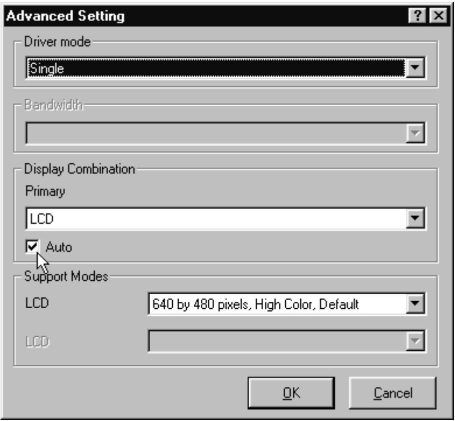
- After that, system will ask you to reboot the computer for taking effect of the new setting and click Yes.
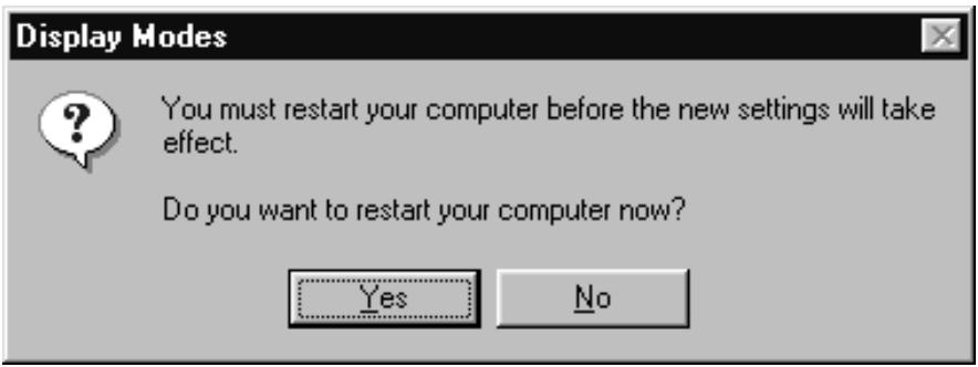
-
In the duration of rebooting, you need to plug in a plug-and-play-capable CRT and set up the external monitor.
-
After repeating the steps 1~6, you should see the following dialogue box. Click the pull bar of driver mode. Set the driver mode option to the one fits your desire.
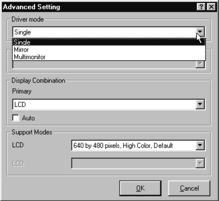
- After the process, system will ask you to reboot the computer for taking effect of the new setting and click Yes.
You have just activated the DualView function.
Description of Driver Mode Options:
| Driver Mode | Function Described |
| Single | With this option selected, either the LCD equipped or the CRT attached would be active. |
| Mirror | It is available to simultaneously display on both the LCD and the external CRT or projector by enabling this function. |
| Multimonitor | This allows user to run two applications across two display device, for instance, Word on LCD, PowerPoint on CRT. |
Desription of Display Combination:
- LCD means the notebook display.
- VGA1 indicates the external CRT.
APPENDIX C
AGENCY REGULATORY NOTICES
Federal Communications Commission Notice
This equipment has been tested and found to comply with the limits for a Class B digital device, pursuant to Part 15 of the FCC Rules. These limits are designed to provide reasonable protection against harmful interference in a residential installation. This equipment generates, uses, and can radiate radio frequency energy and, if not installed and used in accordance with the instructions, may cause harmful interference to radio communications. However, there is no guarantee that interference will not occur in a particular installation. If this equipment does cause harmful interference to radio or television reception, which can be determined by turning the equipment off and on, the user is encouraged to try to correct the interference by one or more of the following measures:
Reorient or relocate the receiving antenna.
Increase the separation between the equipment and the receiver.
- Connect the equipment into an outlet on a circuit different from that to which the receiver is connected.
■ Consult the dealer or an experienced radio or television technician for help.
Modifications
The FCC requires the user to be notified that any changes or modifications made to this device that are not expressly approved by the Manufacture may void the user's authority to operate the equipment.
Connections to Peripheral Devices
Connections to this device must be made with shielded cables with metallic RFI/EMI connector hoods to maintain compliance with FCC Rules and Regulations.
Declaration of Conformity
This device complies with Part 15 of the FCC Rules. Operation is subject to the following two conditions: (1) this device may not cause harmful interference, and (2) this device must accept any interference received, including interference that may cause undesired operation. For questions regarding this declaration, contact:
Uniwill Computer Corporation
14F, No. 67, Section 1, Chung Shan Road
Hsin Chuang City, Taipei Hsin, Taiwan
Use the serial number found on the product for identification.
European Notice
Products with the CE Marking comply with both the EMC Directive (89/336/EEC) and the Low Voltage Directive (73/23/EEC) issued by the Commission of the European Community.
Compliance with these directives implies conformity to the following European Norms:
EN55022 (CISPR 22) Radio Frequency Interference
EN50082 (IEC801-2, IEC801-3, IEC801-4) Electro-magnetic Immunity
EN60950 (IEC950) Product Safety
Canadian Notice
This digital apparatus does not exceed the Class B limits for radio noise emissions from digital apparatus as set out in the radio interference regulations of the Canadian Department of Communications.
Power Cord Requirement
The power cord supplied with the notebook AC adapter should match the plug and voltage requirements for your local area. Regulatory approval for the AC adapter has been obtained using the power cord for the local area. However, if you travel to a different area and need to connect to a different outlet or voltage, you should use one of the power cords listed below. To purchase a power cord (including one for a country not listed below) or a replacement ac adapter, contact your local dealer.
U.S. and Canada
The cord set must be UL Listed and CSA-Certified.
The minimum specifications for the flexible cord are (1) No. 18 AWG, (2) Type SJ, and (3) 3-conductor.
The cord set must have a rated current capacity of at least 10 A.
The attachment plug must be an earth-grounding type with a NEMA 5-15P (15A, 125V) or NEMA 6-15P (15 A, 250V) configuration.
Japan
All components of the cord set (cord, connector, and plug) must bear a T mark and registration number in accordance with the Japanese Dentori Law.
The minimum specification for the flexible cord are: (1) 0.75 mm² conductors, (2) Type VCT or VCTF, and (3) 3-conductor.
The cord set must have minimum rated current capacity of 7 A.
The attachment plug must be a two-pole, grounded type with a Japanese Industrial Standard C8303 (15 A, 125 VAC) configuration.
Other Countries
The cord set fittings must bear the certification mark of the agency responsible for evaluation in a specific country. Acceptable agencies are:
BSI (UK)
OVE (Australia)
CEBEC (Belgium)
SEMKO (Sweden)
DEMKO (Denmark)
SETI (Finland)
EANSW (Australia)
SEV (Switzerland)
IMQ (Italy)
UTE (France)
KEMA (The Nether)
VDE (Germany)
NEMKO (Norway)
The flexible cord must be of a HAR (harmonized) type HO5VV-F 3-conductor cord with a minimum conductor size of 0.03 square inches.
The cord set must have a current capacity of at least 10 A and a nominal voltage rating of 125 / 250 VAC.
Battery Safety
The battery pack is intended to use only with this notebook.
Do not disassemble the pack.
Do not dispose of the battery pack in fire or water.
To avoid risk of fire, burns, or damage to your battery pack, do not allow a metal object to touch the battery contacts.
■ Handle a damaged or leaking battery with extreme care. If you come in contact with the electrolyte, wash the exposed area with soap and water. If it contacts the eye, flush the eye with water for 15 minutes and seek medical attention.
- Do not charge the battery pack if the ambient temperature exceeds 45°C ( 113°F ).
To obtain a replacement battery, contact your local dealer.
- Do not expose the battery pack to high storage temperatures (above 60°C, 140°F ).
When discarding a battery pack, contact your local waste
DISPOSAL provider regarding local restrictions on the disposal or recycling of batteries. Replace only with same or equivalent type recommended by the manufacturer. Discard used batteries according to the manufacturer's instructions or local laws.
The CD-ROM drive used with this notebook are certified as a Class 1 laser device according to the U.S. Department of Health and Human Services (DHHS) Radiation Performance Standard and International Standards IEC 825 / IEC 825-1 (EN60825 / EN60825-1). The device is not considered harmful, but the following precautions are recommended:
Do not open the unit.
Avoid direct exposure to the laser beam.
If the unit requires service, contact an authorized service center.
Ensure proper use by reading and following the instructions carefully.
Do not attempt to make any adjustment of the unit.
CLASS 1 LASER PRODUCT
APPAREIL A LASER DE CLASSE 1
LASERSCHUTZKLASSE 1 PRODUKT
LED (Infrared) Safety
The infrared port located on the left side of this notebook is classified as a Class 1 LED (light-emitting diode) device according to International Standard IEC 825-1 (EN60825-1). This device is not considered harmful, but the following precautions are recommended:
- Do not attempt to view the infrared LED beam with any type of optical device.
Do not attempt to make any adjustment of the unit.
If the unit requires service, contact an authorized service center.
Avoid direct eye exposure to the infrared LED beam. Be aware that the beam is invisible light and cannot be seen.
CLASS1LEDPRODUCT
LEDSCHUTZKLASSE 1 PRODUKT
CD-ROM warning
Warning!
Do not attempt to disassemble the cabinet containing the laser. The laser beam used in this product is harmful to the eyes. The use of optical instruments, such as magnifying lenses, with this product increase the potential hazard to your eyes. For your safety, have this equipment serviced only by an authorized service provider.
CLASS 1 LASER PRODUCT
LASER KLASSE 1
LUOKAN 1 LASERLAITE
APPAReil A LASER DE CLASSE 1
EN608825
Lithium battery warning
This computer contains a lithium battery to power the clock and calendar circuitry.
CAUTION: Danger of explosion if battery is replaced incorrectly. Replace only with the same or equivalent type recommended by the manufacturer. Discard used batteries according to the manufacturer's instructions.
© Copyright Mai, 2000
2. Battery Optimized Performance Mode
Energie- APM 1.2 (Advanced Power Management) &ACPI 1.0 Management (Advanced Configuration Power Interface)
system Microsoft NT 4.0
Department of Health and Human Services (DHHS) und den
Internationalen Standards IEC 825 / IEC 825-1 (EN60825/
LED Systemindicators
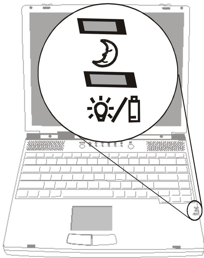
2. De stand Battery Optimized Performance
This digital apparatus does not exceed the Class B limits for radio noise emissions from digital apparatus as set out in the radio interference regulations of the Canadian Department of Communications.
KLASSE 1 LED PRODUKT LEDsCHUTZKLASSE 1 PRODUKT
SPÉCIFICATIONS DU PRODUIT
Federal Communications Commission Notice
This equipment has been tested and found to comply with the limits for a Class B digital device, pursuant to Part 15 of the FCC Rules. These limits are designed to provide reasonable protection against harmful interference in a residential installation. This equipment generates, uses, and can radiate radio frequency energy and, if not installed and used in accordance with the instructions, may cause harmful interference to radio communications. However, there is no guarantee that interference will not occur in a particular installation. If this equipment does cause harmful interference to radio or television reception, which can be determined by turning the equipment off and on, the user is encouraged to try to correct the interference by one or more of the following measures:
Reorient or relocate the receiving antenna.
Increase the separation between the equipment and the receiver.
Connect the equipment into an outlet on a circuit different from that to which the receiver is connected.
Consult the dealer or an experienced radio or television technician for help.
Modifications
The FCC requires the user to be notified that any changes or modifications made to this device that are not expressly approved by the Manufacture may void the user's authority to operate the equipment.
Connections to Peripheral Devices
Connections to this device must be made with shielded cables with metallic RFI/EMI connector hoods to maintain compliance with FCC Rules and Regulations.
Declaration of Conformity
This device complies with Part 15 of the FCC Rules. Operation is subject to the following two conditions: (1) this device may not cause harmful interference, and (2) this device must accept any interference received, including interference that may cause undesired operation. For questions regarding this declaration, contact:
on of the adresses on the back of this manual.
Use the serial number found on the product for identification.
Avis europeen
This digital apparatus does not exceed the Class B limits for radio noise emissions from digital apparatus as set out in the radio interference regulations of the Canadian Department of Communications.
CLASS 1 LASER PRODUCTAPPAREIL ALASER- DE CLASSE 1LASERSCHUTZKLASSE 1 PRODL
CLASS 1 LED PRODUCT LEDsCHUTZKLASSE 1 PRODUKT
CAUTION: Danger of explosion if battery is replaced incorrectly. Replace only with the same or equivalent type recommended by the manufacturer. Discard used batteries according to the manufacturer's instructions.
- TABLE OF CONTENTS
- PREFACE
- GETTING TO KNOW THE BASICS
- BIOS SETUP AND SECURITY
- BATTERY POWER AND POWER MANAGEMENT
- UPGRADING YOUR NOTEBOOK
- TROUBLESHOOTING
- USING THIS MANUAL
- SYMBOLS AND CONVENTIONS
- PROTECTING YOUR NOTEBOOK - AVOID ABUSIVE HANDLING AND ADVERSE ENVIRONMENT FOLLOW THE ADVICE BELOW WILL HELP ENSURE THAT YOU GET THE MOST OUT OF YOUR INVESTMENT
- YOUR COMPUTER WILL SERVE YOU WELL IF YOU TAKE GOOD CARE OF IT
- HERE ARE SOME WAYS OF TAKING CARE OF YOUR AC ADAPTER
- HERE ARE SOME WAYS OF TAKING CARE OF YOUR BATTERY PACK
- WHEN CLEANING THE NOTEBOOK, OBSERVE THESE STEPS
- CONTACT YOUR DEALER OR SEE YOUR SERVICE TECHNICIAN IF ANY OF THE FOLLOWING OCCURS
- SECTION 1
- PERFORMANCE FEATURES
- HIGH PERFORMANCE PROCESSOR
- AGP GRAPHICS
- ADVANCED 3D GRAPHICS AND HARDWARE ACCELERATED MPEG2/DVD PLAYBACK
- MASS STORAGE CAPABILITY
- HIGH FLEXIBILITY DESIGN
- LARGE LCD DISPLAY
- KEYBOARD AND TOUCH PAD
- ADVANCED BATTERY PACK
- A VARIETY OF COMMUNICATIONS
- AUDIO FEATURES
- INTEGRATED I/O PORTS
- SYSTEM AT A GLANCE
- INTERNET HOT KEY WWW
- LED STATUS INDICATORS
- POWER/SUSPEND BUTTON
- BUILT-IN SPEAKERS
- KEYBOARD
- FN KEY
- TOUCH PAD
- LED SYSTEM INDICATORS
- BUILT-IN MICROPHONE
- REAR VIEW
- NOTE
- WARNING
- KENSINGTON SECURITY ANCHOR
- USB PORT
- MODEM PORT
- PS/2 PORT
- STEREO MICROPHONE JACK
- STEREO HEADPHONE JACK
- EXTERNAL VGA PORT
- SERIAL PORT
- PARALLEL PORT
- LAN PORT
- LEFT-SIDE VIEW
- CD-ROM
- CD-ROM EJECT BUTTON
- PC CARD SLOT
- PC CARD EJECT BUTTON
- FIXING SCREW
- HARD DISK DRIVE BAY
- CPU HEATSINK/FAN BAY COVER
- CPU HEATSINK/FAN BAY
- BATTERY LATCHES
- BATTERY PACK
- SECTION 2
- ENTERING THE BIOS SETUP SCREEN
- LEAVING THE BIOS SETUP SCREEN
- BIOS ACTION KEYS
- MODIFYING THE BIOS SETTINGS
- THE SETUP MAIN MENU
- THE MENU OF STANDARD CMO SETUP
- THE DETAILED DESCRIPTION OF HARD DISK DRIVE SETTING
- ENTERING DRIVE PARAMETERS
- THE MENU OF ADVANCED CMOS SETUP
- THE MENU OF POWER MANAGEMENT SETUP
- THE MENU OF PERIPHERAL SETUP
- THE SECURITY ISSUE BY USING PASSWORD PROTECTION TWO LEVELS OF PASSWORD PROTECTION
- THE OPTION OF AUTO-DETECT HARD DISK
- THE OPTION OF AUTO CONFIGURATION WITH OPTIMAL SETTINGS
- THE OPTION OF AUTO CONFIGURATION WITH FAIL-SAFE SETTINGS
- THE OPTION OF SAVE SETTINGS AND EXIT
- SECTION 3
- THE BATTERY PACK
- NI-MH / LITHIUM-ION BATTERY
- ACTIONS TO BATTERY WARNING
- INSTALLING AND REMOVING THE BATTERY PACK
- TO DETACH THE BATTERY PACK
- TO INSTALL THE BATTERY PACK
- CHARGING THE BATTERY AND CHARGING TIME
- CHECKING THE BATTERY LEVEL
- PROLONGING THE BATTERY'S LIFE AND USAGE CYCLES
- USING POWER MANAGEMENT
- SUSPEND MODE
- SUSPEND
- SAVE TO DISK
- THE SUSPEND BUTTON
- THE LCD PANEL SWITCH
- POWER CONSUMPTION OF THE LCD DISPLAY
- CREATING THE SAVE TO DISK PARTITION (OR FILE)
- TO RESIZE OR CREATE THE SAVE TO DISK PARTITION, DO THE FOLLOWING
- ABOUT WINDOWS 98 POWER MANAGEMENT FEATURE
- SECTION 4
- UPGRADING THE HARD DISK DRIVE
- EXPANDING THE HARD DISK DRIVE
- TO REPLACE THE HARD DISK DRIVE, DO THE FOLLOWING
- UPGRADING THE SYSTEM MEMORY
- EXPANDING THE DIMM MODULE IN THE ORIGINAL SOCKET
- TO EXPAND THE DIMM, DO THE FOLLOWING
- INSTALLING THE DIMM MODULE IN THE EXPANSION SOCKET
- REMOVING THE DIMM MODULE IN THE EXPANSION SOCKET
- SECTION 5
- TROUBLE SHOOTING
- BEFORE TAKING FURTHER ACTIONS, CONSIDER THE FOLLOWING SUGGESTIONS
- AUDIO PROBLEMS
- NO SPEAKER OUTPUT
- SOUND CAN NOT BE RECORDED
- HARD DISK PROBLEMS
- THE HARD DISK DRIVE DOES NOT SPIN
- THE HARD DRIVE IS MAKING ABNORMAL WHINING NOISES
- THE HARD DISK DRIVE HAS REACHED ITS CAPACITY
- THE HARD DISK PERFORMS PRETTY SLOW
- THE FILES ARE CORRUPTED
- CD-ROM PROBLEMS
- THE CD-ROM DRIVE DOES NOT WORK
- THE CD-ROM DRIVE DOSE NOT READ ANY CDS
- FLOPPY DISK PROBLEMS
- THE FLOPPY DISK DOES NOT WORK PROPERLY
- THE FLOPPY DRIVE DOES NOT SAVE
- THE DISKETTE DOES NOT EJECT FROM THE DRIVE
- DISPLAY PROBLEMS
- THE DISPLAY PANEL IS BLANK WHEN THE SYSTEM IS TURNED ON
- THE SCREEN IS DIFFICULT TO READ
- KEYBOARD AND POINTING DEVICE (MOUSE) PROBLEMS
- THE BUILT-IN KEYBOARD ACCEPTS NO INPUT
- THE EXTERNAL PS/2 OR SERIAL MOUSE DOES NOT WORK
- THE BUILT-IN TOUCH PAD DOES NOT WORK
- THE BUILT-IN TOUCH PAD PERFORMS ERATICALLY
- THE CHARACTERS ON THE SCREEN REPEAT WHILE I TYPE
- CMOS PROBLEM
- A MESSAGE “CMOS CHECKSUM FAILURE” DISPLAYS DURING THE BOOTING PROCESS
- INFRARED PROBLEMS
- THE INFRARED COMMUNICATION PORT DOES NOT WORK
- MEMORY PROBLEMS
- THE POST DOES NOT SHOW AN INCREASED MEMORY CAPACITY WHEN YOU HAVE ALREADY INSTALLED ADDITIONAL MEMORY
- THE O/S ISSUES AN INSUFFICIENT MEMORY ERROR MESSAGE DURING OPERATION
- MODEM PROBLEMS
- THE BUILT-IN MODEM DOES NOT RESPOND
- THE FAX/MODEM DISCONNECTS DURING TRANSMISSION
- THE FAX/MODEM DOESN'T TRANSMIT PROPERLY
- NETWORK ADAPTER PROBLEMS
- THE ETHERNET ADAPTER DOES NOT WORK
- THE ETHERNET ADAPTER DOES NOT APPEAR TO OPERATE IN THE 100MBPS TRANSMISSION MODE
- PC CARD (PCMCIA) PROBLEMS
- PC CARDS DO NOT FUNCTION
- THE PC CARD CAN NOT BE RECOGNIZED
- WINDOWS CRASHES OR FREEZES WHEN YOU REMOVE THE PC CARD
- PERFORMANCE PROBLEMS
- THE NOTEBOOK BECOMES HOT
- THE PROGRAM APPEARS STOPPED OR RUNS VERY SLOWLY
- POWER, START, AND BATTERY PROBLEMS
- THE NOTEBOOK POWERS DOWN AS SOON AS IT IS POWERED ON
- THE NOTEBOOK BEEPS INTERMITTENTLY
- THE BATTERY LIFE GETS SHORTER AND SHORTER
- THE BATTERY DOES NOT CHARGE
- PRINTING PROBLEMS
- THE PRINTER DOES NOT PRINT
- THE PRINTER DOES NOT PRINT WHAT'S ON THE SCREEN
- THE PRINTER DOES NOT RESPOND TO INFRARED COMMUNICATION
- SERIAL, PARALLEL, AND USB PROBLEMS
- THE DEVICE THAT ATTACHED TO THE SERIAL PORT IS NOT WORKING
- THE PARALLEL PORT DOES NOT WORK
- THE USB DEVICE DOES NOT WORK
- APPENDIX A
- PROCESSOR AND CORE LOGIC
- SYSTEM MEMORY
- LCD
- GRAPHICS
- STORAGE CAPACITY
- AUDIO
- MODEM
- LAN
- OTHER STANDARD HARDWARE
- PC CARD
- PORTS
- POWER
- BIOS
- OPERATING SYSTEM
- PHSICAL SPECIFICATION
- APPENDIX B
- WINDOWS 98 DISPLAY DRIVER INSTALLATION / UPDATE
- TO INSTALL/UPDATE THE DRIVER, DO THE FOLLOWING
- USING THE DUALVIEW FUNCTION
- IMPORTANT
- DESRIPTION OF DISPLAY COMBINATION
- APPENDIX C
- FEDERAL COMMUNICATIONS COMMISSION NOTICE
- MODIFICATIONS
- CONNECTIONS TO PERIPHERAL DEVICES
- DECLARATION OF CONFORMITY
- EUROPEAN NOTICE
- CANADIAN NOTICE
- POWER CORD REQUIREMENT
- U.S. AND CANADA
- JAPAN
- OTHER COUNTRIES
- BATTERY SAFETY
- LED (INFRARED) SAFETY
- CD-ROM WARNING
- LITHIUM BATTERY WARNING
- BATTERY OPTIMIZED PERFORMANCE MODE
- LED SYSTEMINDICATORS
- DE STAND BATTERY OPTIMIZED PERFORMANCE
- SPÉCIFICATIONS DU PRODUIT
- AVIS EUROPEEN
Brand : MAXDATA
Model : VISION 450T
Category : Laptop