X4 SINUS 1500 RT - Inverter INFOSEC - Free user manual and instructions
Find the device manual for free X4 SINUS 1500 RT INFOSEC in PDF.
| Brand | INFOSEC |
| Model | X4 SINUS 1500 RT |
| Product Type | Pure Sine Wave UPS (Double Conversion) |
| Power | 1500 VA |
| Input Voltage | Single Phase 110-240 V |
| Output Voltage | Configurable: 110, 120, 208, 220, 230, 240 V |
| Frequency | 50/60 Hz (Auto-sensing) |
| Batteries | Internal, Lead-Acid, Hot-swappable |
| Runtime | Varies by load (full recharge 5h) |
| Protection | AVR (Boost/Buck), Surge Arrest, Surge Suppression |
| Outlets | Essential and Programmable |
| Communications | USB, RS-232, SNMP Slot |
| Display | LCD Status Screen |
| Audible Alarms | Battery Mode, Low Battery, Overload, Fault |
| EPO Function | Emergency Power Off via Connector |
| Software | InfoPower (Included) |
| Safety | CE Compliance, Electric Shock Protection |
| Maintenance | Disconnect before cleaning, damp cloth |
| Repairability | User Replaceable Batteries |
| Mounting | Rack (2U) or Tower |
| Weight | Approx. 12 kg |
Frequently Asked Questions - X4 SINUS 1500 RT INFOSEC
User questions about X4 SINUS 1500 RT INFOSEC
0 question about this device. Answer the ones you know or ask your own.
Ask a new question about this device
Download the instructions for your Inverter in PDF format for free! Find your manual X4 SINUS 1500 RT - INFOSEC and take your electronic device back in hand. On this page are published all the documents necessary for the use of your device. X4 SINUS 1500 RT by INFOSEC.
USER MANUAL X4 SINUS 1500 RT INFOSEC
1. SAFETY INSTRUCTIONS - Security
IMPORTANT!
Installing and connecting UPSs in a way that does not comply with accepted practices releases Infosec Communication from any liability.
1.1 Risk of electric shock:
The UPS unit uses potentially hazardous voltages. Do not attempt to disassemble this equipment as it does not contain accessible components that can be repaired by users.
All repairs should be performed by qualified technicians only.
The utility power outlet shall be near the equipment and easily accessible. To isolate the UPS from AC input, turn it off and then remove the plug from the utility power outlet.
The UPS has its own internal power supply (battery). There is a risk that output sockets may still be live after the UPS has been disconnected from the mains power supply.
In an emergency situation, switch the UPS to the "Off" position and disconnect the unit from the AC power supply.
When the UPS is out of order, please refer to section: "trouble shooting" and call the hot line.
1.2 Connected products:
Combined UPS and connected equipment leakage current should not exceed 3.5mA .
Make sure that the connected load does not exceed UPS capabilities. To ensure improved backup time and longer battery life, we recommend a load equivalent to 1/3 of nominal power.
Do not plug the UPS input into its own output socket.
Do not plug the UPS into a power strip or surge suppressor.
The UPS has been designed for personal computers. It should not be used with electrical or electronic equipment with inductive loads such as motors or fluorescent lights.
Do not connect any household appliances such as microwaves, vacuum cleaners, hair dryers or life-support systems to the UPS.
Due to excessive consumption, laser printers should not be connected to the UPS.
Please replace the fuse only with the same type and amperage in order to avoid fire hazards.
1.3 Good disposals of the device:
The mains outlet that supplies the UPS shall be located near the UPS and shall be easily accessible.
Install the UPS in a temperature and humidity-controlled indoor area free of conductive interference.
It should not be exposed to direct sunlight or sources of heat. Do not cover the ventilation slots.
Disconnect the UPS from AC power before cleaning with a damp cloth (no cleaning products).
Do not leave any recipients containing liquid on or near the UPS.
1.4 About batteries:
It is recommended that a qualified technician change the battery.
Do not dispose of the battery in a fire as it may explode.
Do not open or damage the battery! The electrolyte, fundamentally sulphuric acid, can be toxic and harmful to the skin and eyes. If you come into contact with it, wash thoroughly with water and clean dirtied clothes.
Do not throw the battery into a fire. It may explode. It has to be disposed of separately at the end of its useful life. Refer to local legislation and regulations.
The UPS contains large-capacity batteries. To avoid any danger of electric shock do not open it/them. If a battery needs servicing or has to be replaced, please contact the distributor.
Servicing should be performed or supervised by competent personnel who take the necessary precautions. Keep unauthorized personnel away from batteries.
A battery can present a risk of electric shock and cause short circuits. The following precautions should be observed by the qualified technician:
Remove watches, rings or other metal objects from hands.
Use tools with insulated handles.
Disconnect the charging source prior to connecting or disconnecting battery terminals.
- When replacing batteries, use the same type and number of sealed lead-acid batteries.
1.5 CE conformity (IEC model):

This logo means that the IEC product answers to the EMC and LVD standards (regarding to the regulation associated with the electric equipment voltage and the electromagnetic fields).
IMPORTANT
An UPS belongs to the electronic and electrical equipment category. At the end of its useful life it must be disposed of separately and in an appropriate manner.
This symbol is also affixed to the batteries supplied with this device, which means they too have to be taken to the appropriate place at the end of their useful life.
Contact your local recycling or hazardous waste centre for information on proper disposal of the used battery.
2. INSTALLATION AND SETUP
NOTE: Before the installation of the unit, please inspect it. Be sure that nothing inside the package is damaged. Please keep the original package in a safe place for future use.
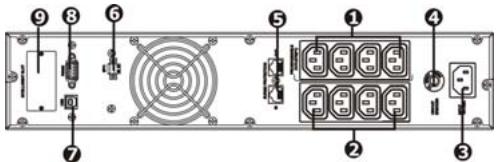
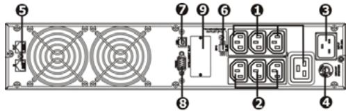
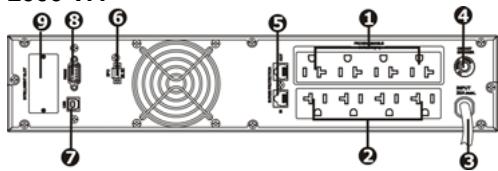
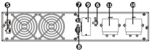
2.1 Rear panel view
X4 SINUS RT IEC 1500/2000 VA
X4 SINUS RT IEC 3000 VA
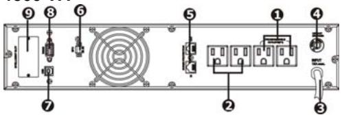
X4 SINUS RT NEMA 1500 VA
X4 SINUS RT NEMA 2000 VA
X4 SINUS RT NEMA 3000 VA
1 - Programmable outlets: connect to non-critical loads.
2 - Output receptacles: connect to mission-critical loads.
3 - AC input.
4 - Input circuit breaker.
5 - Network/Fax/Modem surge protection.
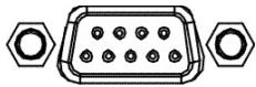
6 - Emergency Power Off function connector (EPO).
7 - USB communication port.
8 - RS-232 communication port.
9 - SNMP intelligent slot.
10 - Input terminal.
11 - Output terminal.
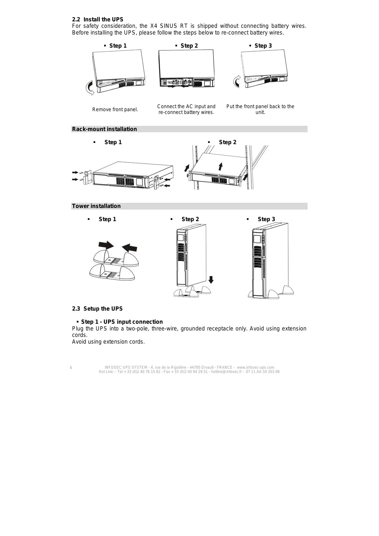
2.2 Install the UPS
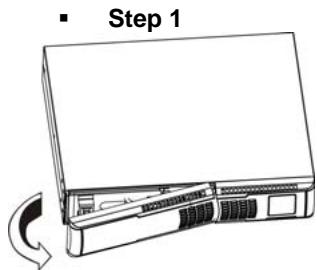
For safety consideration, the X4 SINUS RT is shipped without connecting battery wires. Before installing the UPS, please follow the steps below to re-connect battery wires.
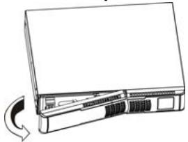
- Step 1
Remove front panel.
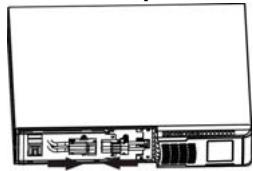
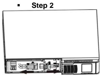
Step 2
Connect the AC input and re-connect battery wires.
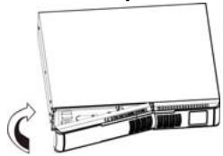
- Step 3
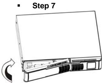
Put the front panel back to the unit.
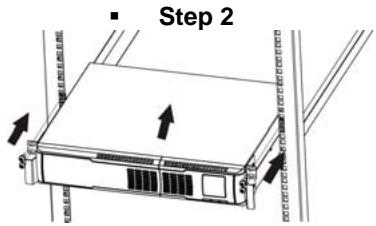
Rack-mount installation
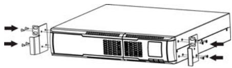
Step 1
Tower installation
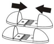
Step 1
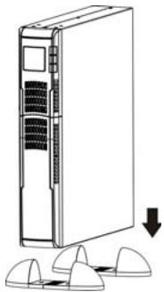
Step 2
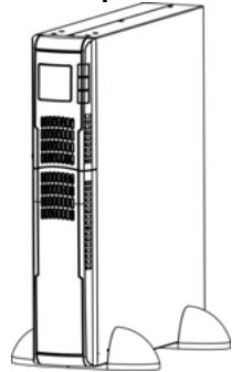
Step 3
2.3 Setup the UPS
- Step 1 - UPS input connection
Plug the UPS into a two-pole, three-wire, grounded receptacle only. Avoid using extension cords.
Avoid using extension cords.
- Step 2 - UPS output connection
For socket-type outputs, there are two kinds of outputs: programmable outlets and general outlets. Please connect non-critical devices to the programmable outlets and critical devices to the general outlets. During power failure, you may extend the backup time to critical devices by setting shorter backup time for non-critical devices.
- Step 3 - Communication connection
Communication ports:

USB port
RS-232 port
Intelligent slot
To allow unattended UPS shutdown/start-up and status monitoring, connect the communication cable one end to the USB/RS-232 port and the other to the communication port of your PC. With the monitoring software installed, you can schedule UPS shutdown/start-up and monitor UPS status through PC.
The UPS is equipped with intelligent slot perfect for either SNMP or AS400 card. When installing either SNMP or AS400 card in the UPS, it will provide advanced communication and monitoring options.
PS: USB port and RS-232 port can't work at the same time.
- Step 4 - Network connection
Network/Fax/Phone surge port

Connect the modem/phone/fax line into surge-protected "IN" outlet on the back panel of the UPS unit. Connect from "OUT" outlet to the equipment with another modem/fax/phone line cable.
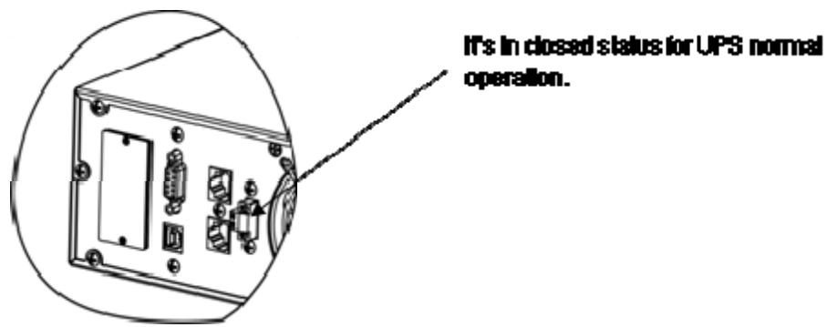
- Step 5 - Disable and enable EPO function
Keep the pin 1 and pin 2 closed for UPS normal operation. To activate EPO function, cut the wire between pin 1 and pin 2.
- Step 6 - Turn on the UPS
Press the ON/MUTE button on the front panel for two seconds to power on the UPS.
Note: The battery charges fully during the first five hours of normal operation. Do not expect full battery run capability during this initial charge period.
- Step 7 - Install software
For optimal computer system protection, refer to the InfoPower software CD to fully configure UPS shutdown.
2.4 Battery replacement
NOTICE: This UPS is equipped with internal batteries and user can replace the batteries without shutting down the UPS or connected loads (hot-swappable battery design). Replacement is a safe procedure, isolated from electrical hazards.
CAUTION! Consider all warnings, cautions, and notes before replacing batteries.
Note: Upon battery disconnection, equipment is not protected from power outages.
Remove front panel.
Disconnect battery wires.
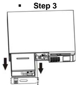
Pull out the battery box by removing two screws on the front panel.
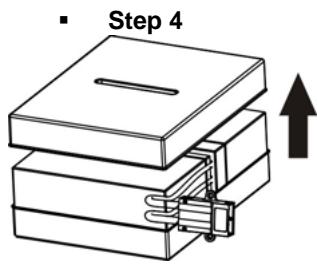
Remove the top cover of battery box and replace the inside batteries.
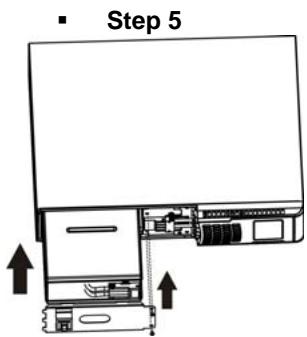
After replacing the batteries, put the battery box back to original location and screw it tightly.
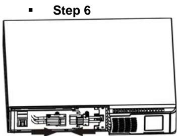
Re-connect the battery wires.
Put the front panel back to the unit.
3. OPERATIONS
3.1 Buttons operation

| Buttons | Functions |
| ON/MUTE button | Turn on the UPS: Press and hold ON/MUTE button for at least 2 seconds to turn on the UPS.Mute the alarm: When the UPS is turned on in battery mode, press and hold this button for at least 5 seconds to disable or enable the alarm system. This is not applied to the situations when warnings or errors occur.Up selection key: Press this button to display previous selection in UPS setting mode.Switch to UPS self-test mode: Press and hold ON/MUTE buttons for 5 seconds to enter UPS self-testing while in AC mode. |
| OFF/ENTER button | Turn off the UPS: Press and hold this button at least 2 seconds to turn off the UPS.Confirm selection key: Press this button to confirm selection in UPS setting mode. |
| SELECT button | Switch LCD message: Press this button to change the LCD message for input voltage, input frequency, battery voltage, output voltage and output frequency.Setting mode: Press and hold this button for 5 seconds to enter UPS setting mode only when UPS is off.Down election key: Press this button to display next selection in UPS setting mode. |
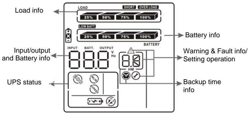
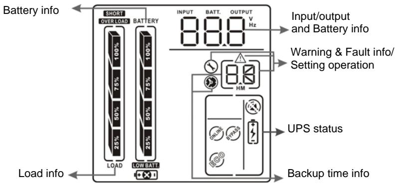
3.2 LCD panel
1) Rack display
2) Tower display
| Display | Functions |
| Backup time information | |
| Indicates the backup time in pie chart. | |
| Indicates the backup time in numbers. H: hours; M: minute. | |
| Warning & fault information | |
| Indicates that warning and fault occur. | |
| Indicates the warning and fault codes (codes are listed in details page 12). | |
| Setting operation | |
| Indicates the setting operation. | |
| Input/Output & battery information | |
| INPUT BATT. OUTPUT V Hz | Indicates the input/output voltage, input/output frequency or battery voltage. V: voltage; Hz: frequency. |
| Load information | |
| LOAD 25% 50% 75% 100% | Indicates the load level by 0-25%, 26-50%, 51-75%, and 76-100%. |
| OVER LOAD | Indicates overload. |
| SHORT | Indicates that the load or the UPS output is short circuited. |
| UPS status | |
| Indicates that programmable management outlets are working. | |
| Indicates that the UPS alarm is disabled. | |
| Indicates the UPS powers the output directly from the mains (See details page 13). | |
| Indicates that the battery charger is working (See details page 13). | |
| Indicates that the UPS is working in boost mode (See details page 13). | |
| Indicates that the UPS is working in buck mode (See details page 13). | |
| Battery information | |
| 25% 50% 75% 100% BATTERY | Indicates the battery level by 0-25%, 26-50%, 51-75% and 76-100%. |
| LOW BATT | Indicates low battery. |
| + | Indicates a problem with the battery. |
3.3 Audible alarms
| Battery mode | Sounding every 4 seconds. |
| Low battery | Sounding every second. |
| Overload | Sounding twice every second. |
| Fault | Continuously sounding. |
3.4 LCD display wording index
| Abbreviations | Display content | Meaning |
| ENA | ENR | Enable |
| DIS | DIS | Disable |
| ESC | ESC | Escape |
| EP | EP | EPO |
| FA | FA | Fan |
| TP | TP | Temperature |
| CH | CH | Charger |
| RAC | RAC | Rack display |
| TOE | TOE | Tower display |
| SF | SF | Site Fault |
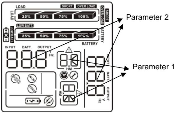
3.5 UPS setting
There are two parameters to set up the UPS:
Parameter 1 – Program alternatives. There are 4 programs to set up: output voltage setting, programmable outlets enable/disable, programmable outlets setting, LCD display direction and exit.
Parameter 2 - Setting figures.
1) Output voltage setting
| Interface | Setting figures |
| LOAD OUTPUT BATTERY | For 110/120/208/220/230/240 VAC models, you may choose the following output voltage: 110: presents output voltage is 110 VAC. 120: presents output voltage is 120 VAC. 208: presents output voltage is 208 VAC. 220: presents output voltage is 220 VAC. 230: presents output voltage is 230 VAC. 240: presents output voltage is 240 VAC. |
2) Programmable outlets enable/disable
| Interface | Setting figures |
| LOAD BATTERY ERA 02 | ENA: Programmable outlets enable. DIS: Programmable outlets disable. |
3) Programmable outlets setting
| Interface | Setting figures |
| LOAD BATTERY 999 0-999 for programmable outlets which connect to non-critical devices on battery mode. | Setting the backup time limits in minutes from 0-999 for programmable outlets which connect to non-critical devices on battery mode. |
4)LCD display direction setting
| Interface | Setting figures |
| LOAD BATTERY HAC 04 | RAC: The LCD display is horizontal. TOE: The LCD display is vertical. |
5) Exit
Examples of steps to follow for setting the parameters:
| Step 1 - Before entering setting mode, make sure that the UPS is in Stand-by mode (off-charging) and that the battery is connected. The LCD display is shown as right. | |
| Step 2 - Press and hold the "Selection" button for 5 seconds to enter Setting mode. | |
| Step 3 - Press the "Up" button (ON/MUTE) to switch to "02" of program list. Then press "Enter" button to enter value setting of parameter 2. Press the "Up" button to change the value to "ENA" to enable the programmable outlet function. Then press "Enter" button again to confirm the setting. | |
| Step 4 - Press the "Up" button (ON/MUTE) again to switch to "03" of program list. Then press "Enter" button for setting programmable outlet time. Push "Up" button to change the value of backup time according your demand. Then press "Enter" to confirm the setting. | |
| Step 5 - Press "Up" button (ON/MUTE) to switch to "00" of program list. Then press "Enter" button to exit setting menu. | |
| Step 6 - Disconnect AC input and wait until the LCD display is off. The new setting will be activated when turning on the UPS again. | |
3.6 Operating mode and description
| Operating mode | Description | LCD display |
| ECO mode | When the input voltage is within voltage acceptable range, UPS will power the output directly from the mains. | LOAD 25° 50° 75° 25° 50° 75° 100° OUTPUT 220V OK BATTERY OK |
| Buck mode when AC is normal | When the input voltage is higher than the voltage regulation range but lower than high loss point, the buck AVR will be activated. | LOAD 25% 50% 25% 75% 220 V BATTERY |
| Boost mode when AC is normal | When the input voltage is lower than the voltage regulation range but higher than low loss point, the boost AVR will be activated. | LOAD 25% 50% 25% 75% 220 V BATTERY |
| Battery mode | When the input voltage is beyond the acceptable range or power failure and alarm is sounding every 4 seconds, UPS will backup power from battery. | LOAD 25% 50% 25% 75% 220 V BATTERY |
| Standby mode | UPS is powered off, there is no output supply power, but the batteries can be charged. | LOAD 25% 50% 25% 75% 220 V BATTERY |
3.7 Faults reference code
| Fault event | Fault code | Icon | Fault event | Fault code | Icon |
| Bus start fail | 01 | x | Inverter output short | 14 | SHORT |
| Bus over | 02 | x | Battery voltage too high | 27 | x |
| Bus under | 03 | x | Battery voltage too low | 28 | + |
| Inverter soft start fail | 11 | x | Over temperature | 41 | x |
| Inverter voltage high | 12 | x | Over load | 43 | OVER LOAD |
| Inverter voltage high | 13 | x |
3.8 Warning indicators
| Warnings | Icons (flashing) | Alarms |
| Low battery | LOW BATT! | Sounding every second. |
| Overload | OVER LOAD! | Sounding twice every second. |
| Battery is not connected | 1 +1! | Sounding every second. |
| Overcharge | 25% 50% 75% 100% | Sounding every second. |
| Site wiring fault | 5F! | Sounding every second. |
| EPO enable | EP! | Sounding every second. |
| Fan failure | FA! | Sounding every second. |
| Over temperature | EP! | Sounding every second. |
| Charger failure | CH! | Sounding every second. |
| Battery fault | +! | Sounding every second. |
4. TROUBLESHOOTING
If the UPS system does not operate correctly, please solve the problem by using the table below.
| Symptoms | Possible causes | Remedy |
| No indication and alarm even though the main is normal. | The AC input power is not correctly connected. | Check if input power cord firmly connected to the mains. |
| The AC input is connected to the UPS output. | Plug AC input power cord to AC input correctly. | |
| The icon flashing on LCD display and alarm is sounding every second. | EPO function is activated. | Set the circuit in close position to disable EPO function. |
| The icon flashing on LCD display and alarm is sounding every second. | Line and neutral conductors of UPS input are reversed. | Rotate mains power socket by 180° and then connect to UPS system. |
| The icon and | The external or internal battery is incorrectly connected. | Check if all batteries are connected well. |
| flashing on LCD display and alarm is sounding every second. | ||
| Fault code is shown as 27 and the icon is lighting on LCD display and alarm is continuously sounding. | Battery voltage is too high or problem with the charger. | Contact your dealer. |
| Fault code is shown as 28 and the icon is lighting on LCD display and alarm is continuously sounding. | Battery voltage is too low or problem with the charger. | Contact your dealer. |
| The icon and the icon OVER LOAD are flashing on LCD display and alarm is sounding twice every second. | UPS is overloaded. | Remove excess loads from UPS output. |
| Fault code is shown as 43 and The icon OVERLOAD is lighting on LCD display and alarm is continuously sounding. | The UPS shut down automatically because of an overload at the UPS output. | Remove excess loads from UPS output and restart it. |
| Fault code is shown as 14 and alarm is continuously sounding. | The UPS shut down automatically because short circuit occurs on the UPS output. | Check output wiring and if connected devices are in short circuit status. |
| Fault code is shown as 1, 2, 3, 11 and 41 on LCD display and alarm is continuously sounding. | A UPS internal fault has occurred. | Contact your dealer |
| Battery backup time is shorter than nominal value | Batteries are not fully charged. | Charge the batteries for at least 5 hours and then check capacity. If the problem still persists, consult your dealer. |
| Batteries defect. | Contact your dealer to replace the battery. | |
| The icon and the warning code flashing on LCD display and alarm is sounding every second. | Fan is locked or doesn't working properly. | Check fans and notify dealer. |
5. STORAGE AND MAINTENANCE
5.1 Warning indicator
The UPS system contains no user-serviceable parts. If the battery service life (3~5 years at 25^ ambient temperature) has been exceeded, the batteries must be replaced. In this case, please contact your dealer.
5.2 Storage
Before storing, charge the UPS 5 hours. Store the UPS covered and upright in a cool, dry location. During storage, recharge the battery in accordance with the following table:
| Storage Temperature | Recharge Frequency | Charging Duration |
| -25°C - 40°C | Every 3 months | 1-2 hours |
| 40°C - 45°C | Every 2 months | 1-2 hours |