GA-H77-DS3H - Motherboard GIGABYTE - Free user manual and instructions
Find the device manual for free GA-H77-DS3H GIGABYTE in PDF.
Download the instructions for your Motherboard in PDF format for free! Find your manual GA-H77-DS3H - GIGABYTE and take your electronic device back in hand. On this page are published all the documents necessary for the use of your device. GA-H77-DS3H by GIGABYTE.
USER MANUAL GA-H77-DS3H GIGABYTE
GA-H77TN GA-B75TN GA-H61TN User's Manual
Declaration of Conformity We, Manufacturerlmporer, G:B.T. Technology Trading GMbH Address: Bullenkoppel 16, 22047 Hamburg, Germany Declare inat tne product Produet Type: | Motherboard Produet Name: GAH77TN conforms with ine essential requirements of the following directives: E 2004n08Ec Emc F1 Condueton & Radiated Emissions: ENS5022.2096+A1:2007 F1 immunty ENS5024:1098+A1:2001+A2:2008 FA Power-ine harmonies: [A Power-ine FA 200688 c LVD ni FA Sato: EN60950-1:2006+A11:2009 FA 2011/65/EU RoHS Direct use of ceain ‘This product does not contain any of ne restricted sronic equipment. substances listed in Annex in concar FA GE martin Signature: Am Mag Date: an 31,201 Name Timmy Huang
DECLARATION OF CONFORMITY
Responsible Party Name:G.B.T. INC. (U.S.A.) Address: 17358 Railroad Street City of Industry, CA 91748 Phone/Fax No: (626) 854-9338/ (626) 854-9326 hereby declares that the product Product Name: Motherboard Model Number: GA-H77TN Conforms to the following specifications: Subpart B, Section 15.107(a) and Section 15.109 Supplementary Information: This device complies with part 15 ofthe FCC Rules. Operation is subject to the ns: (1) This device may not cause harmful and (2) this device must accept any inference received, including that may cause undesired operation. lowing two condi Representative Persons Name: ERIC LU Signature: Eric Lu Date: Jan. 31, 2013
Declaration of Conformity We, Manufacturerlmporer, G:B.T. Technology Trading GMbH Address: Bullenkoppel 16, 22047 Hamburg, Germany Declare inat tne product Produet Type: | Motherboard Produet Name: GA-B7STN conforms with ine essential requirements of the following directives: E 2004n08Ec Emc F1 Condueton & Radiated Emissions: ENS5022.2096+A1:2007 F1 immunty ENS5024:1098+A1:2001+A2:2008 FA Power-ine harmonies: [A Power-ine FA 200688 c LVD ni FA Sato: EN60950-1:2006+A11:2009 FA 2011/65/EU RoHS Direct use of ceain ‘This product does not contain any of ne restricted sronic equipment. substances listed in Annex in concar FA GE martin Signature: Am Mag Date: an 31,201 Name Timmy Huang
DECLARATION OF CONFORMITY
Responsible Party Name:G.B.T. INC. (U.S.A.) Address: 17358 Railroad Street City of Industry, CA 91748 Phone/Fax No: (626) 854-9338/ (626) 854-9326 hereby declares that the product Product Name: Motherboard Model Number: GA-B75TN Conforms to the following specifications: Subpart B, Section 15.107(a) and Section 15.109 Supplementary Information: This device complies with part 15 ofthe FCC Rules. Operation is subject to the ns: (1) This device may not cause harmful and (2) this device must accept any inference received, including that may cause undesired operation. lowing two condi Representative Persons Name: ERIC LU Signature: Eric Lu Date: Jan. 31, 2013
Declaration of Conformity We, Manufacturerlmporer, G:B.T. Technology Trading GMbH Address: Bullenkoppel 16, 22047 Hamburg, Germany Declare inat tne product Produet Type: | Motherboard Produet Name: GAHGTTN conforms with ine essential requirements of the following directives: E 2004n08Ec Emc F1 Condueton & Radiated Emissions: ENS5022.2096+A1:2007 F1 immunty ENS5024:1098+A1:2001+A2:2008 FA Power-ine harmonies: [A Power-ine FA 200688 c LVD ni FA Sato: EN60950-1:2006+A11:2009 FA 2011/65/EU RoHS Direct use of ceain ‘This product does not contain any of ne restricted sronic equipment. substances listed in Annex in concar FA GE martin Signature: Am Mag Date: Feb ca, 2013 Name Timmy Huang
DECLARATION OF CONFORMITY
Responsible Party Name:G.B.T. INC. (U.S.A.) Address: 17358 Railroad Street City of Industry, CA 91748 Phone/Fax No: (626) 854-9338/ (626) 854-9326 hereby declares that the product Product Name: Motherboard Model Number: GA-H61TN Conforms to the following specifications: Subpart B, Section 15.107(a) and Section 15.109 Supplementary Information: This device complies with part 15 ofthe FCC Rules. Operation is subject to the ns: (1) This device may not cause harmful and (2) this device must accept any inference received, including that may cause undesired operation. lowing two condi Representative Persons Name: ERIC LU Signature: Eric Lu Date: Feb. 08, 2013
Copyright © 2013 GIGA-BYTE TECHNOLOGY CO. LTD. All rights reserved. The trademarks mentioned in this manual are legally registered to their respective owners. Disclaimer Information in this manual is protected by copyright laws and is the property of GIGABYTE. Changes to the specifications and features in this manual may be made by GIGABYTE without prior notice. No part of this manual may be reproduced, copied, translate, transmitted, or published in any form or by any means without GIGABYTE's prior written permission. Documentation Classifications In order to assist in the use ofthis product, GIGABYTE provides the following types of documentations: m For detailed product information, carefully read the User's Manual. For product-related information, check on our website at: http:/www.gigabyte.com
Table of Contents Box Contents … GA-H77TN/GA-B75TN/GA-H61TN Motherboard Layout
Chapter 1 Hardware Installation
1-1 Installation Precautions 1-2 Product Specifications. ee 1-3 Installing the CPU and CPU Cookr. 1-4 Installing the Memory/Expansion Card 1-5 Back Panel Connectors. 1-6 Internal Connectors.…
Chapter 2 BIOS Setup.
Box Contents GA-H77TN or GA-B75TN or GA-H61TN motherboard Motherboard driver disk Users Manual One SATA power cable 1/0 Shield Screws kit for expansion cards HKRRRARA The box contents above are for reference only and the actual iems shall depend on the product package you obtain.
® Only for GA-H77TN. @ Only for GA-B7STN. @® Only for GA-H6ATN.
Installation Precautions The motherboard contains numerous delicate electronic circuits and components which can become damaged as a result of electrostatic discharge (ESD). Prior to installation, carefully read the user's manual and follow these procedures: Prior to installation, make sure the chassis is suitable for the motherboard. Prior to installation, do not remove or break motherboard S/N (Serial Number) sticker or warranty sticker provided by your dealer. These stickers are required for warranty validation. Always remove the AC power by unplugging the power cord from the power outlet before installing or removing the motherboard or other hardware components. When connecting hardware components to the internal connectors on the motherboard, make sure they are connected tightly and securely. When handling the motherboard, avoid touching any metal leads or connectors. It is best to wear an electrostatic discharge (ESD) wrist strap when handling electronic components such as a motherboard, CPU or memory. If you do not have an ESD wrist strap, keep your hands dry and first touch a metal object to eliminate static electricity. Prior to installing the motherboard, please have it on top of an antistatic pad or within an electrostatic shielding container. Before unplugging the power supply cable from the motherboard, make sure the power supply has been turned off. Before turning on the power, make sure the power supply voltage has been set according to the local voltage standard. Before using the product, please verify that all cables and power connectors of your hardware components are connected. To prevent damage to the motherboard, do not allow screws to come in contact with the motherboard circuit or its components. Make sure there are no leftover screws or metal components placed on the motherboard or within the computer casing. Do not place the computer system on an uneven surface. Do not place the computer system in a high-temperature environment. Turning on the computer power during the installation process can lead to damage to system components as well as physical harm to the user. If you are uncertain about any installation steps or have a problem related to the use of the product, please consult a certified computer technician.
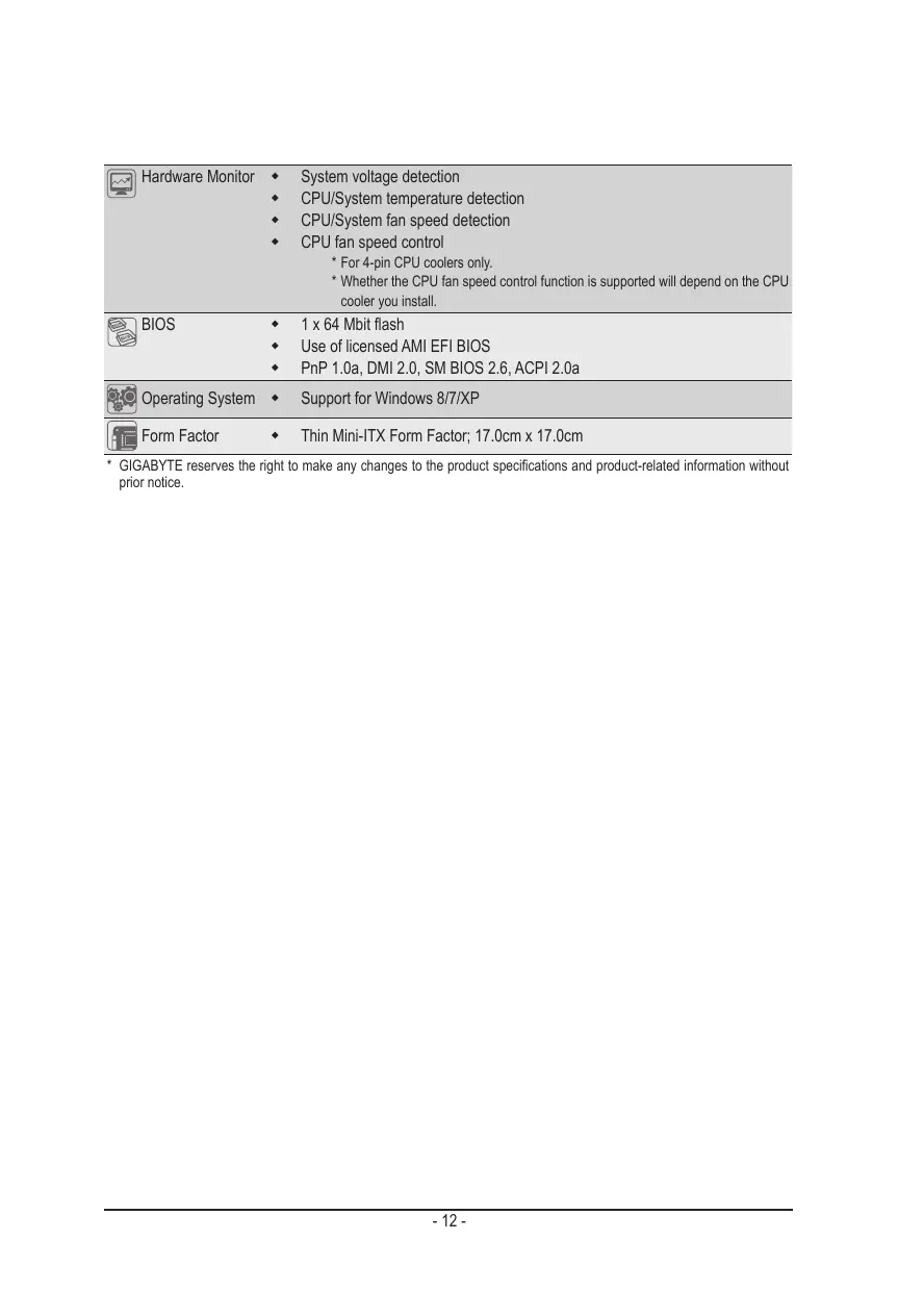
1-2 Product Specifications CPU + Support for tels Core” 17 processors/Intel® Core” 15 processors! Intel® Core” 13 processors/ntel® Pentium® processors/Intel® Celeron® processors in the LGAÏ155 package (Supports up to 77W) (Go to GIGABYTE's website for the latest CPU support list.) L3 cache varies with CPU © Chipset + Intels H77 @/B75 @/H61 © Express Chipset "enr + 2x1.5V DDR3 SO-DIMM sockets supporting up to 8 GB of system memory
- Due to a Windows 32-bt operating system limitation, when more than 4 GB of physical memory is installed, the actual memory size displayed will be less than {he size of he physical memory installed. Dual channel memory architecture Support for DDR3 1600/1333/1066/800 MHz memory modules (Go to GIGABYTE'S website for the latest supported memory speeds and memory modules.) foros Graphies + Integrated Graphics Processor: = 1 x HDMI 1.3 port, supporing a maximum resolution of 1920x1200 = 1 x DisplayPort, supporting a maximum resolution of 2560x1600 -_1xLVDS connector Reallek® ALCB87 codec: High Definition Audio 2/415.1/7.1-channel *_ To configure 5.1/7.-channel audio, you have to use an HD front panel audio module and enable the muli-channel audi feature through the audio driver. 1x Realtek® GbE LAN chip (10/10/1000 Mbit) Dsrrsensus + 1x PCI Express x4 slot (Supports 2EW only) (The PCIEX4 slot conforms to PCI Express 3.0 standard.) 1 x Mini PCI Express x1 slot Storage Interface + Chipset: GAHTTIN: = 2XSATA6Gb/S connectors (SATAO/1) supporing up to 2 SATAGb/ devices = 2XSATA3Gb/S connectors (SATA2/3) supporing up to 2 SATA 3Gb/ devices = 1xmSATAconnector = Support for RAID 0, RAID 1, RAID 5, and RAID 10 GA-B75TN = 1x SATA6Gb/ connector (SATAD) supporing up to 1 SATA GGb/s device = 3xSATASGb/S connectors (SATAH/2/3) supporng up to 3 SATA 3Gb's devices: = 1xmSATAconnector GAHGITN: = 3x SATA3Gb/S connectors (SATAO/1/2) supporng up to 3 SATA 3Gb's devices = 1xmSATA connector ® Only for GA-H77TN. @ Only for GA-B7STN. @® Only for GA-H6ATN.
- For 4-pin CPU coolers only.
- Whether the CPU fan speed control function is supported will depend on the CPU cooler you install. 3 BIOS L 1x 64 Mbit flash Use of licensed AMI EFI BIOS PnP 1.0a, DMI 2.0, SM BIOS 2.6, ACPI 2.0a Re Operating System + Support for Windows 8/7/XP (Form Factor . Thin Mini-ITX Form Factor, 17.0cm x 17.0cm
- GIGABYTE reserves the right to make any changes lo the product speciications and product-related information without prior notice.
1-3 Installing the CPU and CPU Cooler Read the following guidelines before you begin to install the CPU/CPU cooler: À Make sure that the motherboard supports the CPU. (Go to GIGABYTE's website for he latest CPU support list) AWays turn off the computer and unplug the power cord from the power outlet before instaling the CPU to prevent hardware damage. Locate the pin one of the CPU. The CPU cannot be inserted if oriented incorrectiy. (Or you may locate the notches on both sides of the CPU and alignment keys on the CPU socket.) Apply an even and thin layer of thermal grease on the surface of the CPU. Do not turn on the computer if the CPU cooler is not installed, otherwise overheating and damage of the CPU may occur. Set the CPU host frequency in accordance with the CPU speciications. is not recommended that the system bus frequency be set beyond hardware speciications since it does not meet the standard requirements for the peripherals. you wish to set the frequency beyond the standard specifications, please do so according to your hardware speciications including the CPU, graphics card, memory, hard drive, etc. For instaling the CPU cooler, please refer to chassis user's manual. 1-4 Installing the Memory/Expansion Card Make sure that the motherboard supports the memory. ILis recommended that memory of the same capacity, brand, speed, and chips be used. (Go to GIGABYTE's website for the latest supported memory speeds and memory modules.) Make sure the motherboard supports the expansion card. Carefully read the manual that came with your expansion card. AWays tu off the computer and unplug the power cord from the power outlet before installing the memory/expansion card to prevent hardware damage. Memory modules have a foolproof design. À memory module can be installed in only one direction. If you are unable to insert the memory, switch the direction. î Read the following guidelines before you begin to install the memory
© DC Power Jack Connect the DC power to this port. © RJ-45 LAN Port The Gigabit Ethemet LAN port provides Internet connection at up to 1 Gbps data rate. The following describes the states of the LAN port LEDs. Connection! | State Description State Description LAN Por © DP (DisplayPort) Connector DisplayPott is a digital display interface which is primarily used to connect a video source to a display device such as a computer monitor, though it can also be used to transmit audio, USB, and other forms of data. @ HDMI Port The HDMI (High-Definition Multimedia Interface) provides an all-digital audio/video interface to transmit the uncompressed audio/video signals and is HDCP compliant. Connect the HDMI audio/video device to this port. The HDMI Technology can support a maximum resolution of 1920x1200 but the actual resolutions supported depend on the monitor being used. HDMI device. (The item name may differ by operating system. Refer the figures below for details.), and enter BIOS Setup, then set Onboard VGA output connect to D-SUB/HDMI under Advanced BIOS Features. Please note the HDMI audio output only supports AC3, DTS and 2-channel-LPCM formats. (AC3 and DTS require the use of an extemal decoder for decoding.) æ + When After installing the HDMI device, make sure the default device for sound playback is the
© USB 3.0 Ports D@ The USB port supports the USB 3.0 specification. Use this port for USB devices such as a USB keyboard/mouse, USB printer, USB flash drive and etc. © USB 2.0 Ports © The USB port supports the USB 2.0 specification. Use this port for USB devices such as a USB keyboard/mouse, USB printer, USB flash drive and etc. & Line Out (Front Speaker Out/Green) The default Line Out (Front Speaker Out) jack. Stereo speakers, earphone or front surroundspeakers can be connected to Line Out (Front Speaker Out) jack. @ MIC In (Pink) The default MIC In jack. Microphone cab be connected to MIC In jack. device and then remove it from the motherboard. + When removing the cable, pull it straight out from the connector. Do not rock it side to side to prevent an electrical short inside the cable connector. î + When removing the cable connected to a back panel connector, first remove the cable from your ® Only for GA-H77TN. @ Only for GA-B75TN. @® Only for GA-H6ATN.
1-6 Internal Connectors
Read the following guidelines before connecting extemal devices: First make sure your devices are compliant with he connectors you wish to connect. Before instaling the devices, be sure to turn off the devices and your computer. Unplug the power cord from the power outlet to prevent damage to the devices. After instaling the device and before tuning on the computer, make sure the device cable has been securely aftached to the connector on the motherboard.
Connect the power switch, reset switch, speaker, chassis intrusion switch/sensor and system status indicator on the chassis to this header according to the pin assignments below. Note the positive and negative pins before connecting the cables. Pin No. | Signal Name HD+ MPD+ HD- MPD-
PW+ RST PW- WF_LED Definition Hard Disk LED Signal anode (+) Power LED Signal anode (+) Hard Disk LED Signal cathode(-) Power LED Signal cathode(-) Ground Power Button anode (+) Reset Button Power Button cathode(-) if active LED Signal The front panel design may differ by chassis. À front panel module mainly consists of power switch, reset switch, power LED, hard drive activity LED, speaker and etc. When connecting your chassis front panel module to this header, make sure the wire assignments and the pin assignments are matched correctiy.
2) SATAO (SATA 6Gb/s Connector} D @
The SATA connectors conform to SATA 6Gb/s standard and are compatible with SATA 3Gb/s and SATA 1.5Gb/s standard. Each SATA connector supports a single SATA device. SATAO (SATA 3Gb/s Connector) ® The SATA connectors conform to SATA 3Gb/s standard and are compatible with SATA 1.5Gbjs standard. Each SATA connector supports a single SATA device. Pin No. | Definition GND TxP TXN GND Only for GA-H77TN. Only for GA-B75TN. Only for GA-H61TN. ee © RXN RXP GND
ee © SATA (SATA 6Gb/s Connector) D The SATA connectors conform to SATA 6Gb/s standard and are compatible with SATA 3Gb/s and SATA 1.5Gb/s standard. Each SATA connector support a single SATA device. SATA (SATA 3Gb/s Connector) 2 ® The SATA connectors conform to SATA 3Gb/s standard and are compatible with SATA 1.5Gb/s standard. Each SATA connector supports a single SATA device. Pin No. | Definition T | GND 2 [TP Sara TN 1j? 4 [evo 5 |RXN 6 [RE
SATA2 (SATA 3Gb/s Connector) The SATA connectors conform to SATA 3Gb/s standard and are compatible with SATA 1.5Gb/s standard. Each SATA connector supports a single SATA device. a Pin No. | Defniion GND
The SATA connectors conform to SATA 3Gb/s standard and are compatible with SATA 1.5Gbjs standard. Each SATA connector supports a single SATA device. Pin No. | Definition T | GND 2 [TP SATAS TN 2 j7 4 [evo 5 [RN 6 [RE
The front panel audio header supports Intel® High Definition audio (HD) and AC'97 audio. You may connect your chassis front panel audio module to this header. Make sure the wire assignments of the module connector match the pin assignments of the motherboard header. Incorrect connection between the module connector and the motherboard header will make the device unable to work or even damage Pin No. | Definition FMICL GND FMICR GPIO_DET FUINER
GND No Pin FLINEL 10 [FINE JD + Audio signals will be present on both of the front and back panel audio connections simultaneousiy. + Some chassis provide a front panel audio module that has separated connectors on each ire instead of a single plug. For information about connectng the front panel audio module that has différent wire assignments, please contact the chassis manufacturer. æ: The front panel audio header supports HD audio by default.
The FPD is a high-speed interface connecting the output of a video controler in a laptop computer, computer monitor or LCD television set to the display panel. Most laptops, LCD computer monitors and LCD TVs use this interface internally. The headers conform to FPD specification. = Pin No. | Defniion
LVDS stands for Low-voltage differential signaling, which uses high-speed analog circuit techniques to provide multgigabit data transfers on copper interconnects and is a generic interface standard for high-speed data transmission. Pin No. | Definition Pin No. | Definition 1 |ODDlaneëP | 21 [NC 2 [ODDlLanëN | 2 |EDID33V 3 |ODDlane2P | 23 |LCD GND 4 [ODDILan2N | 24 |LCD GND 5 |ODDlaneiP | 25 |LCD GND
13/14) CPU_FAN/SYS_FAN (Fan Headers) All fan headers on this motherboard are 4-pin. Most fan headers possess a foolproof insertion design: When connectng a fan cable, be sure to connect in the correct orientation (the black connector wire is the ground wire). The speed control function requires the use of a fan with fan speed control design. For optimum heat dissipation, i is recommended that a system fan be installed inside the chassis 1 Pin No. | Definiion
“ EU 3 Sense es 4 | Speed Control SFA + Be sure to connect fan cables to the fan headers to prevent your CPU and system from overheating. Overheating may resul in damage to the CPU or the system may hang +_ These fan headers are not configuration jumper blocks. Do not place a jumper cap on the headers.
This power connector is for the integrated 19V chassis power supply. Pin No. | Defnition T_[ew 2 [#w
17) MON_SW (Flat panel display switch header)
This header allows you to connect an on/off switch for the display. Pin No. | Definition Cr Er 2 [en
The Back Light switch provides the function for screen back light adjustment. Pin No. | Definition 1 | BL DOWN 2 |[BLUP
19) SPKR (Speaker Header)
This header connects to the speaker on the chassis front panel. The system reports system startup status by issuing a beep code. One single short beep will be heard if no problem is detected at system startup. Pin No. | Defniion 1 Speaker OUT L- 2 | Speaker OUT L+ 3 | Speaker OUTRE 4 | Speaker OUTR-
The battery provides power to keep the values (such as BIOS configurations, date, and time information) in the CMOS when the computer is turned off. Replace the battery when the battery voltage drops to a low level, or the CMOS values may not be accurate or may be lost. Pin No. | Definition 1 | RTC Reset 2 [ev + Ahays tum off your computer and unplug the power cord before replaing the battery. VAN + Replace the battery th an equivalent one. Danger ofexplsionfhe battery à replaoed uit an incorrect model. Contact the place of purchase or local dealer if you are not able to replace the battery by yoursef or uncertain about the batery model + Used batteries must be handledin accordance vit local environmental regulations.
21) CLR_ CMOS (Clearing CMOS Jumper)
Use this jumper to clear the CMOS values (e.g. date information and BIOS configurations) and reset the CMOS values to factory defaults. To clear the CMOS values, use a metal object like a screwdriver to touch the two pins for a few seconds. © Open: Normal operation (Default setting) @® Close: Clear CMOS data + Always tum off your computer and unplug the power cord from the power outlet before clearing the CMOS values. +_ After system restart, go to BIOS Setup to load factory defaults (select Load Optimized Defaults) or manually configure the BIOS settings (refer to Chapter 2, "BIOS Setup," for BIOS configurations)
This jumper can be used to provide different screen voltage settings ! 1-2 Close: Set to 3V
This jumper allows you to select the required operating voltage for the backlight panel. 1-2 Close: Set to 12V
This header allows you to connect a WiFi operation indicator LED. Pin No. | Defniion 1 1 | Gen 8 2 [LED WAN
25) SATA_PWR (SATA Power Connector)
This connector provides power to installed SATA devices. Connect the included SATA power cable to 1he SATA_PWR connector. Then connect the SATAloplical drive pour connectors to your hard drive and optical drive.
BIOS (Basic Input and Output System) records hardware parameters of the system in the CMOS on the motherboard. lis major functions include conducting the Power-On Self-Test (POST) during system startup. saving system parameters and loading operating system, etc. BIOS includes a BIOS Setup program that allows the user to modify basic system configuration settings or to activale certain system features. When the power is tumed off, the battery on the motherboard supplies the necessary power to the CMOS to keep the configuration values in the CMOS. To access the BIOS Setup program, press the <F2> key during the POST when the power is tumed on. BIOS flashing is potentally risky, if you do not encounter problems of using the current BIOS À version, it is recommended that you don't flash the BIOS. To flash the BIOS, do it with caution. Inadequate BIOS flashing may result in system malfunction. It is recommended that you not alter {he default settings (unless you need to) to prevent system instability or other unexpected results. Inadequately allering the settings may result in systems failure to boot. If this occurs, try to clear the CMOS values and reset the board to default values. {Refer to the "Restore Defaults” section in this chapter or introductions of the battery/clearing CMOS jumper in Chapter 1 for how to clear he CMOS values.) BIOS Setup Program Function Keys <T><J> Move the selection bar to select an item ce Move the selection bar lo select the screen <Ente> Execute command or enter he submenu Es Main Menu: Exit he BIOS Selup program Submenus: Exit current submenu ES Increase he numeric value or make changes = Decrease lhe numeric value or make changes FF General Help <> Restore he previous BIOS settings for the current submenus > Load the Oplimized BIOS default selings for the current submenus <> Save allthe changes and exit the BIOS Setup program -2B-
Main This setup page includes all the items in standard compatible BIOS Advanced This setup page includes all the items of AMI BIOS special enhanced features. {ex: Auto detect fan and temperature status, automatically configure hard disk parameters.) Chipset Northbridge and Southbridge additional features configuration. Boot This setup page provides items for configuration of boot sequence. Security Change, set, or disable supervisor and user password. Configuration supervisor password allows you to restrict access to the system and BIOS Setup. A supervisor password allows you to make changes in BIOS Setup. Auser password only allows you to view the BIOS settings but not to make changes. Save & Exit Save all the changes made in the BIOS Setup program to the CMOS and exit BIOS Setup. (Pressing <F10> can also carry out this task.) Abandon all changes and the previous settings remain in effect. Pressing <Y> to the confirmation mes- sage will exit BIOS Setup. (Pressing <Esc> can also carry out his task.)
2-1 The Main Menu Once you enter the BIOS Setup program, the Main Menu (as shown below) appears on the screen. Use arrow keys to move among he items and press <Enter> to accept or enter other sub-menu. Main Menu Help The on-screen description of a highlighted setup option is displayed on the bottom line of the Main Menu. Submenu Help While in a submenu, press <F1> to display a help screen (General Help) of function keys available for the menu. Press <Esc> to exit the help screen. Help for each item is in the Item Help block on the right side of the submenu. (Sample BIOS Version: GA-H77TN F1) access more advanced options. When the system is not stable as usual, select the Restore Defaults item to set your system to its defaults. The BIOS Setup menus described in this chapter are for reference only and may differ by BIOS version. æ I you do not find the settings you want in the Main Menu or à submenu, press <Cir+<F{> to = 30-
Display version of the processor. Compliency Display compliency information. Project Version Display version number of the project. BIOS Build Date and Time Displays the date and time when the BIOS setup utility was created. ‘MAC Address Displays the MAC address information. Total Memory Determines how much total memory is present during the POST. ‘7 Memory Frequency Display the memory frequency information. ME FW Version Display the ME firmware version. System Date Set the date following the weekday-month-day- year format. 7 System Time Set the system time following the hour-minute- second format.
2-2-1 ACPI Settings ‘7 ACPI Sleep State Select the highest ACPI sleep state the system will enter, when the suspend button is pressed. Suspend Disabled/S1 only (CPU Stop Clock}/S3 only (Suspend to RAM). Default setting is S3 only (Suspend to RAM) = 33-
2-2-2 CPU Configuration LEnabie 7 CPU Type Displays the processor type information. ‘7 CPU Signature Displays the processor ID information. ‘ Microcode Patch Display the information of the processor microcode patch. 7 CPU Speed Display the information of the processor speed. ‘Processor Cores Display the information of the processor core. Intel HT Technology Display Intel Hyper Threading Technology function support information. ‘Intel VT-x Technology Display Intel Vitualization Technology function support information. ‘Intel SMX Technology Display Intel Safer Mode Extensions Technology function support information. 7 64-bit Display the supported infprmation of installed CPU. ‘LA Data Cache Display the information of L1 Data Cache. ‘LA Code Cache Display the information of L1 Code Cache.
‘7 L2 Cache Display the information of L2 Cache per Core. 7 L3 Cache Display the information of total L3 Cache per socket. Execute Disable Bit) When this item enabled, the processor prevents the execution of code in data-only memory pages. This provides some protection against buffer overflow attacks. Options available: Enabled/Disabled. Default setting is Enabled. Intel Virtualization Technology !* Select whether to enable the Intel Virtualization Technology function. VT allows a single platform to run multiple operating systems in independent partitions. Options available: Enabled/Disabled. Default setting is Disabled. Se VT.dos) Enables or disables Intel Virtualization Technology for Directed 1/0. (Default: Enabled)
(Note) This item is present only when you install a CPU that supports this feature. For more information about Intel CPUS" unique features, please visit Intel website.
eee SATA Mode elec ICT SATA Mode Selection ® Enables or disables RAID for the SATA controllers integrated in the Intel H77 Chipset or configure the SATA controllers to AHCI mode IDE Configures the SATA controller to IDE mode. » RAID Enables RAID for the SATA controller. » AHCI … Confgures the SATA controllers to AHCI mode. Advanced Host Controller Interface (AHCI) is an interface specification that allows the storage driver to enable advanced Serial ATA features such as Native Command Queuing and hot plug. (Default) SATA Mode Selection ® Allows you to decide whether to configure the SATA controller integrated in the Chipset to AHCI mode. IDE Configures the SATA controller to IDE mode. » AHCI Confgures the SATA controllers to AHCI mode. Advanced Host Controller Interface (AHCI) is an interface specifcation that allows the storage driver to enable advanced Serial ATA features such as Native Command Queuing and hot plug. (Default) Serial ATA Port 0/Serial ATA Port 1/Serial ATA Port 2/Serial ATA Port 30 @/mSATA) The category identifies Serial ATA and mSATA types of hard disk that are installed in the computer. System will automatically detect HD type. Note that the speciications of your drive must match with the drive table. The hard disk wi not work properly if you enter improper information for this category. Hard drive information should be labeled on the outside device casing. Enter the appropriate option based on this information. Only for GA-H77TN. Only for GA-B75TN. Only for GA-H61TN.
rt Technology IDisablecl Intel(R) Rapid Start Technology!" Enable/Disable the Intel Rapid Start Technology (IRSTe) funciton. The IRST enables your system to get up and running faster from even the deepest sleep, saving time and power consumption. Option available: Enabled/Disabled. Default setting is Disabled. Entry on S3 RTC Wake Enable/Disable Entry on S3 RTC Wake function. Option available: Enabled/Disabled. Default setting is Enabled. This item is configurable only when Intel(R) Rapid Start Technology is enabled. Entry After If enabled, will allow you to set a timer to wake the computer at a particular interval. Option available: 10 minutes. Default setting is 10 minutes. This item is configurable only when Intel(R) Rapid Start Technology is enabled. Active Page Threshold Support I enabled, the system will support RST with small partition. Option available: Enabled/Disabled. Default setting is Disabled. This item is configurable only when Intel(R) Rapid Start Technology is enabled. (Note) Advanced items prompt when this item is enabled. = 37-
2-2-5 HIW Monitor Press Enter lo view the Hardware Monitor screen which displays a realtime record of the CPUIsystem tem- peralure, and fan speed, liems on this window are non-configurable. Fan Fa
CPU/System FAN Fail Detect Enable CPU/System Fan Stop Warning function. Option available: Enabled/Disabled. Default setting is Enabled. ‘7 CPU/System SMART FAN Control Enable CPU/System Smart Fan function. Option available: Enabled/Disabled. Default setting is Enabled. 7 SYS FAN Type Select system fan type. Option available: 3 Pin/4 Pin. Default setting is 3 Pin. 7 System/CPU Temperature Displays current system and CPU temperature. ‘7° System/CPU Fan Speed (RPM) Displays current system and CPU and system fan speed. = 3B-
2-2-6 Intel(R) Smart Connect Technology guration ‘7° ISCT Configuration Enables or disables Intel Smart Connect Technology. (Default: Disabled) = 39-
2-2-7 Network Stack °° Network stack Disables or enables booting from the network to install a GPT format OS, such as installing the OS from the Windows Deployment Services server. (Default: Disable Link) ‘7° Ipv4 PXE Support Enables or disables IPv4 PXE Support. This item is configurable only when Network stack is enabled. ‘7° Ipv6 PXE Support Enables or disables IPv6 PXE Support. This item is configurable only when is enabled.
2-2-8 CPU PPM Configuration LEnab1ec) ‘7 EIST (Enhanced Intel SpeedStep Technology) Conventional Intel SpeedStep Technology suitches both voltage and frequency in tandem between high and low levels in response to processor load. Options available: Enabled/Disabled. Default setting is Enabled. ‘°° Turbo Mode When this feature is enabled, the processor can dynamically overclock one or two of it four processing cores to improve performance with applications that are not mult-threaded or optimized for quad-core processors. Options available: Enabled/Disabled. Default setting is Enabled. CPU C3/C6 Report (") Alows you to determine whether to let he CPU enter C3/C6 mode in system halt state. When enabled, the CPU core frequency and voltage will be reduced during system halt state to decrease power con- sumption. The C3/C6 state is a more enhanced power-saving state than C1. Options available: Enabled/Disabled. Default setting is Enabled. Default setting for C3 is Enabled. Default setting for C6 is Enabled. (Note) This item is present only if you install a CPU that supports this feature. For more information about Intel CPUS' unique features, please visit Intel website.
2-3 Chipset Menu LEnab1ec) 7 Azalia Enable/Disable onboard audio controller. Options available: Auto/Enabled/Disabled. Default setting is Enabled. °° Verb Table Define the Verb Table. Mode A does not support DMIC. Mode B supports DMIC. Options available: Mode A/Mode B. Default setting is Mode A. ‘7 Onboard LAN Enable/Disable onboard LAN controller. Options available: Enabled/Disabled. Default setting is Enabled. ‘7 ERP Support Enable/Disable Erp support function. Options available: Enabled/Disabled. Default setting is Disabled. ‘Restore AC Power Loss This option provides user to set the mode of operation if an AC / power loss occurs. Power On: System power state when AC cord is re-plugged. Power Off: Do not power on system when AC power is back. Last State: _ Set system to the last sate when AC power is removed. Options available: Power On/Power Off/Last State. Default setting is Power Off. ‘_ LVDS Control function Enable/Disable LVDS control function. Options available: Enabled/Disabled. Default setting is Enabled.
2-4 Boot Menu The Boot menu allows you to set the drive priority during system boot-up. BIOS setup will display an error message if the drive(s) specified is not bootable.
Bootup NunLock Bootup NumLock State Allows you to select power-on state for NumLock function. Options available: On/Of. Default setting is On. Fast Boot If enabled, the system will speed the boot up time. Options available: Enabled/Disabled. Default setting is Disabled. Boot Option #1/2/3 Press Enter to configure the boot priority. Hard Drive/CD/DVD ROM Drive/Floppy Drive/Network Device BBS Prior Specifies the boot order for a specific device type, such as hard drives, optical drives, floppy disk drives, and devices that support Boot from LAN function, etc. Press <Enter> on this item to enter the submenu that presents the devices of the same type that are connected. This item is present only if at least one device for this type is installed.
CSM parameters LEnab1ec) Launch CSM Enables or disables UEFI CSM (Compatibiity Support Module) to support a legacy PC boot process. > Enabled Enables UEFI CSM. (Default) » Disabled Disables UEFI CSM and supports UEFI BIOS boot process only. Boot option filter Allows you to select which type of operating system to boot. » UEFI and Legacy Allows booting from operating systems that support legacy option ROM or UEFI op- tion ROM. (Default) » Legacy only Allows booting from operating systems that only support legacy Option ROM. » UEFI only Allows booting from operating systems that only support UEFI Option ROM. This item is configurable only when Launch CSM is set to Enabled. Launch PXE OpROM policy Allows you to select whether to enable the UEFI or legacy option ROM for the LAN controller. » Do not launch Disables option ROM. (Default) » Legacy only Enables legacy Option ROM only. + UEFI only Enables UEFI Option ROM only. This item is configurable only when Launch CSM is set to Enabled. Launch Storage OpROM policy Allows you to select whether to enable the UEFI or legacy option ROM for the storage device controller. # Do not launch Disables option ROM. » Legacy Only Enables legacy option ROM only. (Default) + UEFI Only Enables UEFI option ROM only. This item is configurable only when Launch CSM is set to Enabled.
‘7 Launch Video OpROM policy Allows you to select whether to enable the UEFI or legacy option ROM for the video controller. # Do not launch Disables option ROM. » Legacy only Enables legacy option ROM only. (Default) + UEFI only Enables UEFI option ROM only. » Legacy first Enables legacy option ROM first. > UEFI first Enables UEFI option ROM first. This item is configurable only when Launch CSM is set to Enabled. Other PCI device ROM priority Allows you to select whether to enable the UEFI or Legacy option ROM for the PCI device controller other than the LAN, storage device, and graphics controllers. » Legacy OpROM Enables legacy option ROM only. » UEFI OpROM | Enables UEFI option ROM only. (Defauit) This item is configurable only when Launch CSM is set to Enabled.
2-5 Security Menu The Security menu allows you to safeguard and protect the system from unauthorized use by setting up ac- cess passwords. Raministrator There are two types of passwords that you can set:
+ Adminstrator Password Entering this password will allow the user to access and change all settings in the Setup Utility. + User Password Entering this password will restrict a user's access to the Setup menus. To enable or disable this field, a Administrator Password must first be set. À user can only access and modify the System Time, System Date, and Set User Password fields. AdministratorPassword Press <Enter> to configure the Administrator password. User Password Press Enter to configure the user password. System Mode state Display the System Mode state. Secure Boot state Display the System Mode State. Secure Boot Secure Boot requires all the applications that are running during the booting process to be pre-signed with valid digital certificates. This way, the system knows all the files being loaded before Windows 8 loads and gets to the login screen have not been tampered with. Options available: Enabled/Disabled. Default setting is Enabled. -4T-
2-6 Exit Menu The Exit menu displays the various options to quit from the BIOS setup. Highlight any of the exit options then press Enter ‘7 Save Changes and Exit Saves changes made and close the BIOS setup and exit system setup. Options available: Yes/No. ‘7 Discard Changes and Exit Discards changes made and close the BIOS setup and exit system setup . Options available: Yes/No. ‘7 Save Changes and Reset Acte this option to reset system after saving the changes. Options available: Yes/No. ‘7 Discard Changes and Reset Acte this option to reset system after without saving any changes. Options available: Yes/No. ‘7 Save Changes Active this option to save all the changes. ‘7 Discard Changes Discards changes made and close the BIOS setup. ‘Restore Defaults Press <Enter> on this item and then press the <Y> key to load the default BIOS settings. Options available: Yes/No.
Save as User Defaults Press <Enter> on this item and then press the <Y> key to save as user default settings. Options available: Yes/No. Restore User Defaults Press <Enter> on this item and then press the <Y> key lo restore user default settings. Options available: Yes/No. Boot Override Press Enter to configure the device as the boot-up drive. UEFI: Buïlt-in in EFI Shell Press <Enter> on this item to Launch EFI Shell from filesystem device. =50-