— Network Hub — Mode d'emploi PDF")
_SUPERSTACK II ENTRY HUB_24 PORT TP (3C16441) - Network Hub 3COM - Free user manual and instructions
Find the device manual for free _SUPERSTACK II ENTRY HUB_24 PORT TP (3C16441) 3COM in PDF.
| Product Type | 10Base-T Network Hub |
| Brand | 3COM |
| Model | SuperStack II Entry Hub 24 Port TP (3C16441) |
| Number of Ports | 24 RJ45 Ports |
| Transfer Speed | 10 Mbps |
| Dimensions (W x D x H) | 44 x 22 x 4.5 cm |
| Weight | 2.5 kg |
| Power Supply | 100-240 V AC, 50-60 Hz, 30 W |
| Power Consumption | 30 W maximum |
| Operating Temperature | 0 °C to 40 °C |
| Operating Humidity | 10% to 90% non-condensing |
| Safety Standards | IEC950, SELV, mandatory grounding |
| Certifications | Class A (Canada), UL, CSA |
| Installation | Rack-mountable or on flat surface |
| LED Indicators | Power, per-port activity |
| Compatibility | IEEE 802.3 10Base-T |
| Connector Type | RJ45 |
| Maintenance | Clean with a soft, dry cloth |
| Warranty | 1 year (depending on reseller) |
| Included Accessories | Power cord, quick start guide |
Frequently Asked Questions - _SUPERSTACK II ENTRY HUB_24 PORT TP (3C16441) 3COM
User questions about _SUPERSTACK II ENTRY HUB_24 PORT TP (3C16441) 3COM
0 question about this device. Answer the ones you know or ask your own.
Ask a new question about this device
Download the instructions for your Network Hub in PDF format for free! Find your manual _SUPERSTACK II ENTRY HUB_24 PORT TP (3C16441) - 3COM and take your electronic device back in hand. On this page are published all the documents necessary for the use of your device. _SUPERSTACK II ENTRY HUB_24 PORT TP (3C16441) by 3COM.
USER MANUAL _SUPERSTACK II ENTRY HUB_24 PORT TP (3C16441) 3COM
SuperStack™ II Entry Hub
12 Port TP (3C16440) and
24 Port TP (3C16441)
User Guide
3Com®

TECHNICAL INFORMATION
Related Standards
The Entry Hub has been designed and certified to the following standards:
Functional ISO 8802/3, IEEE 802.3
Safety UL 1950, EN 60950, CSA 22.2 #950
EMC EN 55022 Class B, EN 50082-1, FCC Part 15 Class A, CSA C108.8 Class A, VCCI Class 2, AS 3548 Class B*, AS 4252.1
*Category 5 screened cables must be used to ensure compliance with this standard. The use of unscreened cables complies with the Class A requirements.
Environmental EN 60068 (IEC 68)
Physical
Width 440mm (17.3 ins)
Depth 224mm (8.8 ins)
Height 44mm (1.7 ins) or 1U
Weight 2.04kg (4.5lb)
Mounting free standing, or 19^ rack or wall mounted using kit supplied
Electrical
Power Inlet IEC 320
Fuse Protection 2 Amps
12 Port Entry Hub
Power Consumption 34 VA
Power Dissipation 116 BTU/hr
24 Port Entry Hub
Power Consumption 44 VA
Power Dissipation 150 BTU/hr
Environmental
Operating Temperature 0-50°C (32-122°F)
Humidity 0-90% (non-condensing)
Please read the following safety information carefully before installing the Entry Hub.

WARNING: Installation and removal of the unit must be carried out by qualified personnel only.
If installing the unit in a stack with SuperStack II units, it must be installed below the narrower units.
- Connect the unit to an earthed power supply to ensure compliance with safety standards.
It is essential that the socket outlet is near to the unit and is accessible. You can only disconnect the unit by removing the appliance coupler from the unit.
This unit operates under SELV conditions (Safety Extra Low Voltage) according to IEC 950, the conditions of which are maintained only if the equipment to which it is connected is also operational under SELV.
The appliance coupler, that is, the connector to the device itself and not the wall plug, must have a configuration for mating with an EN60320/IEC320 appliance inlet.
Under no circumstances should the unit be connected to an A.C. outlet (power supply) without an Earth (Ground) conection.
France and Peru Only
This unit cannot be powered from IT^ supplies. If your supplies are of IT type, this unit should be powered by 230V (2P+T) via an isolation transformer ratio 1:1, with the secondary connection point labelled Neutral, connected directly to Earth (Ground).
The unit is covered by Oftel General Approval, NS/G/12345/J/100003, for indirect connection to a public telecommunications system. This can only be achieved using the serial port on the unit and an approved modem.
Power Cord Set
This must be approved for the country where it will be used.
USA and Canada
The cord set must be UL-approved and CSA certified.
The minimum specifications for the flexible cord are: No.18 AWG Type SV or SJ 3-conductor
The cord set must have a rated current capacity of at least 10A.
The attachment plug must be an earth-grounding type with a NEMA 5-15P (15A, 125V) or NEMA 6-15P (15A, 250V) configuration.
Denmark
The supply plug must comply with Section 107-2-D1, Standard DK2-1a or DK2-5a.
The supply plug must comply with SEV/ASE 1011.

L'INFORMATION DE SECURITE IMPORTANTE
The SuperStack™ II Entry Hub is a flexible unmanaged Ethernet repeater which is very easy to use. It can be used in a variety of ways, from building a small network to expanding a larger, more established network.
The SuperStack II Entry Hub 12 Port TP (3C16440) has 12 dedicated shielded twisted pair (TP) ports on the front panel. The SuperStack II Entry Hub 24 Port TP (3C16441) has 24 dedicated shielded twisted pair (TP) ports on the front panel. The rear panel also has a slot for a 3Com Transceiver Module or Bridge MicroModule; if fitted, the Module will operate in addition to the TP ports. A range of different media Transceiver Modules is available from 3Com (see "Products and Bulletin Boards").
The Entry Hub is suited for office use where it can be wall-mounted, rack-mounted, or free standing. Alternatively, the unit can be rack-mounted in a wiring closet or equipment room. A mounting kit is supplied.
The Entry Hub can be powered either from the AC mains supply, or through an optional 3Com SuperStack II Advanced RPS (Redundant Power System). Contact your supplier for details.
The Entry Hub comes with:
One power cord for use with the Entry Hub
Four standard height and two reduced height self-adhesive rubber pads
Mounting Kit
A Warranty Registration card for you to fill out and return
Repeater Functions
The Entry Hub has been designed to conform to the IEEE 802.3 Ethernet standard for Local Area Networks, and provides all the standard functions of an 802.3 repeater, including:
Signal retiming
Preamble regeneration
Fragment extension
Automatic partition/reconnection
Network Connections
The Entry Hub can be used stand-alone or linked with other hubs. Because each Entry Hub is a single IEEE 802.3 Ethernet repeater hub, there can be a maximum of four Entry Hubs between any two pieces of Data Terminal Equipment (DTE) (workstations or other equipment) on the same network.
The Entry Hub is ready to use. You can connect the Hub to any DTE fitted with a 10BASE-T network adapter or a 10BASE-T transceiver. Connect one end of the twisted pair cable to the RJ45 port on the unit and the other end to the RJ45 port on your network adapter or transceiver. You can attach up to 12 or 24 twisted pair segments to the front of the unit.
The Entry Hub can use both shielded 150 ohm, and unshielded or shielded 100 ohm twisted pair cables. To remain within 802.3 10BASE-T rules, the maximum length of cable between the unit and any DTE should not be greater than 100m (328 feet). Consult your supplier's technical support department if you need to use twisted pair cables over greater distances.
You can fit one of the 3Com Transceiver Modules or a Bridge MicroModule into the slot on the rear panel (see "Products and Bulletin Boards") to provide an additional 13th or 25th port.
You can connect the Entry Hub to any other 10BASE-T hub or unit using port 12 or 24, to form an inter-repeater link. You must switch port 12 or 24 to MDI to bypass the internal cross-over normally implemented by 10BASE-T unit ports. See "MDI Switch" for information on connecting hubs and switching port 12 or 24 between MDI and MDIX.

HOW TO USE THE ENTRY HUB
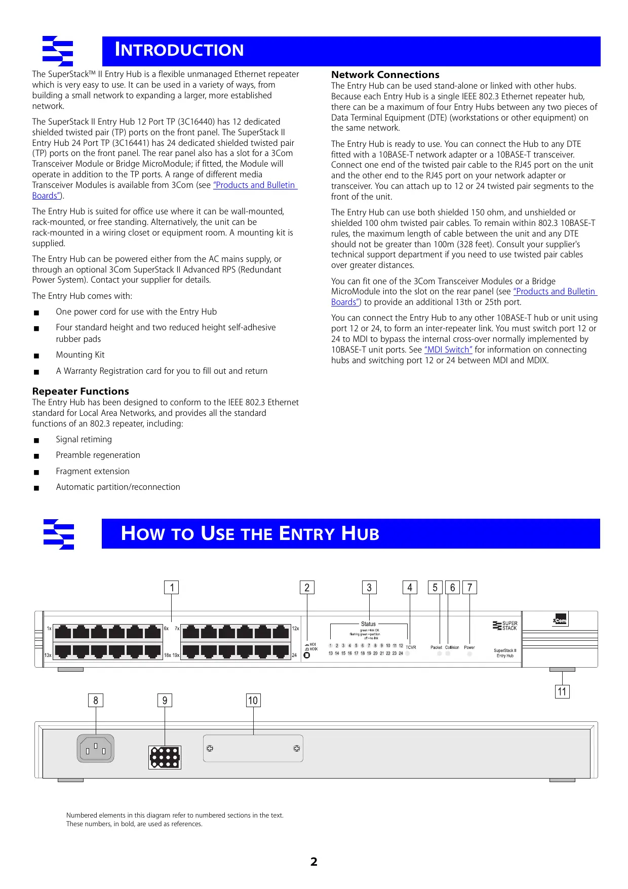
Front Panel
1 12 or 24 RJ45 Ports

WARNING: RJ45 ports. These are shielded RJ45 data sockets. They cannot be used as telephone sockets. Only connect RJ45 data connectors to these sockets.

Either shielded or unshielded data cables with shielded or unshielded jacks can be connected to these data sockets.
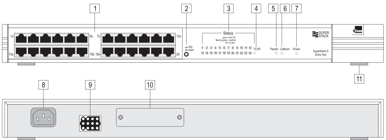
2 MDI Switch
Ports 1 to 11 (12 port hub) and 1 to 23 (24 port hub) are fixed as MDIX ports so that they can be connected directly to DTE (workstations or other equipment) which have MDI ports using normal 'straight through' TP cables.
Port 12 (12 port hub) and 24 (24 port hub) are switch selectable using the MDI Switch. The ports can be MDIX ports (to connect directly to DTE like the other ports), or MDI ports (to connect to other repeaters using a normal 'straight through' TP cable).

Out
In this position you can connect port 12 or 24 to a workstation or any other DTE using a normal 'straight through' TP cable.

In
In this position you can connect port 12 or 24 to any MDIX port on another 10BASE-T repeater using a normal 'straight through' TP cable.
To connect two Entry Hubs, connect port 12 or 24 on unit 1 to any port on unit 2. Ensure that the MDI switch on unit 1 is IN (MDI) and that if port 12 or 24 is used on unit 2, the MDI switch is OUT (MDIX).
3 TP STATUS LEDs
The TP STATUS LEDs show the partition state of a port and whether or not the Link Pulse signal is present on the segment connected to a port:
Green The Link Pulse signal is being received and the segment attached to the port is functional.
The port is partitioned from the network.
green
- Check the connections and the cable for any breaks in the segment.
Make sure the transceiver attached to the DTE is correctly connected and powered up. - Check for illegal 802.3 configurations, in particular, loops.
If the cause of the partition is found and corrected, the segment is reconnected automatically, after the first valid packet is transmitted to, or received from the segment.
Off The Link Pulse signal is not being received.
Check that the attached DTE is switched on.
- Check that the attached transceiver is not faulty.
If it is port 12 or 24 or an inter-repeater link, check the setting of the MDI switch.
- Carry out the checks recommended for when a STATUS LED is flashing green.
- Check for no more than 4 repeater stacks in series, and that cable lengths do not exceed the maximum specified in the standard for that medium.
If these checks do not identify the cause of a problem, it may be that the Entry Hub or the device connected to the port is faulty. Contact your supplier for further advice.
4 Transceiver Module STATUS LED
If a Twisted Pair or Fiber Transceiver Module has been fitted, the LED behaves the same as the TP STATUS LEDs, see 3.
For other Transceiver Modules, the LED shows these states:
Green Transceiver Module fitted correctly and not partitioned.
Flashing Transceiver Module partitioned.
green
Off Transceiver Module is faulty or fitted incorrectly.

A Transceiver Module port connected to a coaxial cable segment may partition if the segment is incorrectly terminated.
The Transceiver Module port may partition if the SQE test pulse is enabled on its transceiver. SQE test should be disabled on transceivers used to connect 802.3 repeaters to the network.
5 Packet LED
The Packet LED flashes green whenever a packet is received on one of the twisted pair ports or the Transceiver Module port.
If this LED does not flash, there are no packets being received by the unit. If the unit is receiving packets but the LED does not flash, the LED has failed. Contact your supplier.
6 Collision LED
The Collision LED flashes yellow when a packet collision has been detected on a segment connected to one of the twisted pair ports or the Transceiver Module port.
Under normal 802.3 Ethernet operation, collisions occur and cause the Collision LED to flash. The probability of collisions increases during heavy activity on the network. The Auto Partition/Reconnection function partitions a segment from the rest of the network if more than 32 consecutive collisions are detected on that segment.
If the Collision LED lights for long periods of time, it indicates a high amount of collisions which can slow your network down. If this happens, you may need to separate parts of your network with a switch. Contact your supplier.
7 Power LED
The Power LED lights green to indicate the power supply to the unit is correct. If it is not lit, and:
None of the ports work
There is a problem with the fuse within the power cord's plug.
The Transceiver Module port does not work, but the twisted pair ports work
The internal fixed fuse for the power supply to the Transceiver Module port has blown. Contact your supplier.
All ports function normally
The LED has failed. Contact your supplier.
Rear Panel Connections
8 Power Supply
The Entry Hub automatically adjusts to the supply voltage. Only use the power cord that is supplied with the Entry Hub.
9 Socket for Redundant Power System
Only connect a 3Com SuperStack II Advanced RPS (Redundant Power System) to this socket. For details, follow the installation instructions in the guide accompanying the Redundant Power System.
10 Transceiver Module Slot
A variety of 3Com plug-in Transceiver Modules or the Bridge MicroModule can be installed in the Entry Hub (see "Products and Bulletin Boards"). Transceiver Modules provide direct network connections to different media.

CAUTION: Do not remove the Transceiver Module blanking plate while the hub is connected to a power source.
Ensure that SQE test is disabled on the Transceiver Module that you are using.
To install a Transceiver Module, refer to the guide that accompanies it. If you subsequently remove the Transceiver Module, you must replace the blanking plate to aid the circulation of cooling air and prevent the entry of dust and debris.
11 Self-adhesive Pads
The Entry Hub is supplied with four standard height and two reduced height self-adhesive rubber pads. Usage of the feet depends on where the Entry Hub is placed:
Use the four standard height pads if the unit is to be placed on a flat surface or stacked with another SuperStack II product of the same dimensions.
Use the two reduced height pads and two of the standard height pads if the unit is to be stacked on a SuperStack II unit of different dimensions — Line up the front of the units, and use the two standard height pads at the front (to fit the recess of the unit beneath) and use the two reduced height pads at the back.

Do not apply the pads if you intend to rack or wall mount the hub.
If the hub is to be part of a free standing stack, apply the pads to each marked corner area on the underside of the hub. Place the hub on top of the lower unit, ensuring that the pads of the upper unit locate with the recesses of the lower unit.
Positioning the Entry Hub

CAUTION: When installing the Entry Hub in a stack of different size units, the Entry Hub must be installed below the narrower units.
When deciding where to position the Entry Hub ensure:
It is accessible and cables can be connected easily.
Cabling is away from:
- sources of electrical noise such as radios, transmitters and broadband amplifiers.
power lines and fluorescent lighting fixtures.
Water or moisture cannot enter the case of the unit.
Air flow around the unit and through the vents in the side of the case is not restricted (3Com recommend that you provide a minimum of 25mm (1 inch) clearance).
To prolong the operational life of your units:
- Never stack units more than six high if free standing, and ensure that cables are supported so that they do not cause the stack to fall over.
Do not place objects on top of any unit or stack.
Do not obstruct any vents at the sides of the case.
Rack or Wall Mounting
The Entry Hub can be mounted in a 19 inch equipment rack, or wall-mounted using the Mounting Kit. See "Mounting Kit Instructions".
Power Up
Use the following sequence to power up the Entry Hub:
Check the network connections and cables.
- Connect the power supply cable to the appropriate power socket on the rear panel of the unit, see 8 or 9.
- Connect the plug to the power supply outlet socket and switch on the power supply at the socket. If you are using a 3Com Redundant Power System, ensure that it is switched on.
When the Entry Hub is powered on, the Power LED should be lit. If it is not, refer to "Power LED", 7.
Spot Checks
At frequent intervals you should visually check the Entry Hub. Regular checks can give you an early warning of a possible failure; any problems can then be attended to when there will be least effect on users. Check the following:
Cabling
Check that all external cabling connections are secure and that no cables are pulled taut.
Cooling fans
Check that the cooling fan is operating by listening to the unit. The fan is fitted near to the front right hand side of the unit (when viewed from the front).
Transceiver Module
Check that the Transceiver Module is connected securely. Refer to the guide that accompanies the Transceiver Module.
What To Do Next?
If the Entry Hub fails to operate successfully, contact your supplier with the following information before returning the unit:
product number and serial number
(printed on a label on the back of the unit)
a brief description of the fault
When returning any equipment to your supplier ensure that the equipment is packed suitably for transit.
Introduction
The Entry Hub is supplied with two mounting brackets and four screws. These are used for rack mounting and wall mounting the unit. When mounting the unit, you should take note of the guidelines given in "Positioning the Entry Hub" overleaf.
Wall Mounting the Units

CAUTION: Disconnect all cables from the unit(s) before continuing. Remove the self-adhesive pads from the underside of the unit(s), if already fitted.
Fitting the brackets to wall mount one unit:
1 Place the unit the right way up on a hard, flat surface with the front facing towards you.
2 Locate a mounting bracket over the mounting holes on one side of the unit, as shown in figure 1 below.
3 Insert the two screws and fully tighten with a screwdriver.
Repeat the last two steps for the other side of the unit.
Fitting the brackets to wall mount two units:
1 Stack the units the right way up on a hard, flat surface with the front facing towards you.
2 Locate two mounting brackets over the mounting holes on one side of the units, as shown in figure 2 below.
3 Insert the three screws and fully tighten with a screwdriver.
Repeat the last two steps for the other side of the units.
To wall mount the unit(s):
Ensure that the wall you are going to use is smooth, flat, dry and sturdy. Attach a piece of plywood (12'' × 20'' × 0.5'') securely to the wall if necessary, and mount the unit(s) as follows:
1 Position the unit(s) against the wall (or plywood) ensuring that the ventilation holes face sideways. Mark on the wall the position of the screws holes for both wall brackets. Drill the four holes.
2 Using suitable fixings and screws (not provided), attach the unit(s) securely to the wall (or plywood).
Reconnect all cables.
Rack Mounting the Units
The Entry Hub is 1U high and will fit a standard 19 inch rack.

CAUTION: Disconnect all cables from the unit before continuing. Remove the self-adhesive pads from the underside of unit, if already fitted.
1 Place the unit the right way up on a hard, flat surface with the front facing towards you.
2 Locate a mounting bracket over the mounting holes on one side of the unit, as shown in figure 3 below.
3 Insert the two screws and fully tighten with a suitable screwdriver.
4 Repeat the two previous steps for the other side of the unit.
5 Insert the unit into the 19" rack and secure with suitable screws (not provided).
Reconnect all cables.
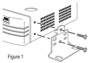
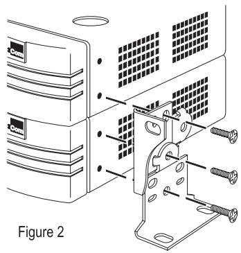
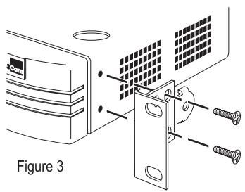
Figure 1
Figure 2
For first five years +5 Lifetime Limited Warranty
The SuperStack II Entry Hub (3C16440 and 3C16441) benefits from 3Com's enhanced +5 Lifetime Limited Warranty. This provides a full 5 years of advanced hardware exchange from your date of purchase in accordance with 3Com's standard terms and conditions. To qualify, you must submit your warranty registration card to 3Com. After the initial 5 year period, the warranty reverts to 3Com's standard lifetime limited warranty. The +5 Lifetime Limited Warranty is not offered or is void where restricted or prohibited by law.
After first five years Lifetime Limited Warranty
The duration of the 3Com standard lifetime limited warranty is lifetime, excluding the power supply and fans. See below for terms and conditions of this warranty.
HARDWARE: 3Com warrants its hardware products to be free from defects in workmanship and materials, under normal use and service, for the following lengths of time from the date of purchase from 3Com or its Authorized Reseller:
Network adapters
Lifetime
Other hardware products
One year (unless otherwise specified above)
Spare parts and spares kits
90 days
If a product does not operate as warranted above during the applicable warranty period, 3Com shall, at its option and expense, repair the defective product or part, deliver to Customer an equivalent product or part to replace the defective item, or refund to Customer the purchase price paid for the defective product. All products that are replaced will become the property of 3Com. Replacement products may be new or reconditioned. Any replaced or repaired product or part has a ninety (90) day warranty or the remainder of the initial warranty period, whichever is longer.
3Com shall not be responsible for any software, firmware, information, or memory data of Customer contained in, stored on, or integrated with any products returned to 3Com for repair, whether under warranty or not.
SOFTWARE: 3Com warrants that the software programs licensed from it will perform in substantial conformance to the program specifications therefor for a period of ninety (90) days from the date of purchase from 3Com or its Authorized Reseller. 3Com warrants the media containing software against failure during the warranty period. No updates are provided. 3Com's sole obligation with respect to this express warranty shall be (at 3Com's discretion) to refund the purchase price paid by Customer for any defective software products, or to replace any defective media with software which substantially conforms to 3Com's applicable published specifications. Customer assumes responsibility for the selection of the appropriate applications program and associated reference materials. 3Com makes no warranty or representation that its software products will work in combination with any hardware or applications software products provided by third parties, that the operation of the software products will be uninterrupted or error free, or that all defects in the software products will be corrected. For any third party products listed in the 3Com software product documentation or specifications as being compatible, 3Com will make reasonable efforts to provide compatibility, except where the non-compatibility is caused by a "bug" or defect in the third party's product.
STANDARD WARRANTY SERVICE: Standard warranty service for hardware products may be obtained by delivering the defective product, accompanied by a copy of the dated proof of purchase, to 3Com's Corporate Service Center or to an Authorized 3Com Service
Center during the applicable warranty period. Standard warranty service for software products may be obtained by telephoning 3Com's Corporate Service Center or an Authorized 3Com Service Center, within the warranty period. Products returned to 3Com's Corporate Service Center must be pre-authorized by 3Com with a Return Material Authorization (RMA) number marked on the outside of the package, and sent prepaid, insured, and packaged appropriately for safe shipment. The repaired or replaced item will be shipped to Customer, at 3Com's expense, not later than thirty (30) days after receipt of the defective product by 3Com.
WARRANTIES EXCLUSIVE: IF A 3COM PRODUCT DOES NOT OPERATE AS WARRANTYED ABOVE, CUSTOMER'S SOLE REMEDY FOR BREACH OF THAT WARRANTY SHALL BE REPAIR, REPLACEMENT, OR REFUND OF THE PURCHASE PRICE PAID, AT 3COM'S OPTION. TO THE FULL EXTENT ALLOWED BY LAW, THE FOREGOING WARRANTYES AND REMEDIES ARE EXCLUSIVE AND ARE IN LIEU OF ALL OTHER WARRANTYES, TERMS, OR CONDITIONS, EXPRESS OR IMPLIED, EITHER IN FACT OR BY OPERATION OF LAW, STATUTORY OR OTHERWISE, INCLUDING WARRANTYES, TERMS, OR CONDITIONS OF MERCHANTABILITY, FITNESS FOR A PARTICULAR PURPOSE, AND SATISFACTORY QUALITY. 3COM NEITHER ASSUMES NOR AUTHORIZES ANY OTHER PERSON TO ASSUME FOR IT ANY OTHER LIABILITY IN CONNECTION WITH THE SALE, INSTALLATION, MAINTENANCE OR USE OF ITS PRODUCTS.
3COM SHALL NOT BE LIABLE UNDER THIS WARRANTY IF ITS TESTING AND EXAMINATION DISCLOSE THAT THE ALLEGED DEFECT IN THE PRODUCT DOES NOT EXIST OR WAS CAUSED BY CUSTOMER'S OR ANY THIRD PERSON'S MISUSE, NEGLECT, IMPROPER INSTALLATION OR TESTING, UNAUTHORIZED ATTEMPTS TO REPAIR OR MODIFY, OR ANY OTHER CAUSE BEYOND THE RANGE OF THE INTENDED USE, OR BY ACCIDENT, FIRE, LIGHTNING, OR OTHER HAZARD.
LIMITATION OF LIABILITY: TO THE FULL EXTENT ALLOWED BY LAW 3COM ALSO EXCLUDING FOR ITSELF AND ITS SUPPLIERS ANY LIABILITY, WHETHER BASED IN CONTRACT OR TORT (INCLUDING NEGLIGENCE), FOR INCIDENTAL, CONSEQUENTIAL, INDIRECT, SPECIAL, OR PUNITIVE DAMAGES OF ANY KIND, OR FOR LOSS OF REVENUE OR PROFITS, LOSS OF BUSINESS, LOSS OF INFORMATION OR DATA, OR OTHER FINANCIAL LOSS ARISING OUT OF OR IN CONNECTION WITH THE SALE, INSTALLATION, MAINTENANCE, USE, PERFORMANCE, FAILURE, OR INTERRUsION OF ITS PRODUCTS, EVEN IF 3COM OR ITS AUTHORIZER RESELLER HAS BEEN ADVISED OF THE POSSIBILITY OF SUCH DAMAGES, AND LIMITS ITS LIABILITY TO REPAIR, REPLACEMENT, OR REFUND OF THE PURCHASE PRICE PAID, AT 3COM'S OPTION. THIS DISCLAIMER OF LIABILITY FOR DAMAGES WILL NOT BE AFFECTED IF ANY REMEDY PROVIDED HEREIN SHALL FAIL OF ITS ESSENTIAL PURPOSE.
Some countries, states, or provinces do not allow the exclusion or limitation of implied warranties or the limitation of incidental or consequential damages for certain products supplied to consumers or the limitation of liability for personal injury, so the above limitations and exclusions may be limited in their application to you. This warranty gives you specific legal rights which may vary depending on local law.
GOVERNING LAW: This Limited Warranty shall be governed by the laws of the state of California.
3Com Corporation, 5400 Bayfront Plaza, Santa Clara, CA 95052-8145 U.S.A. Tel: 1 (408) 764-5000
9/1/96

ELECTRO-MAGNETIC COMPATABILITY
FCC Statement
This equipment has been tested and found to comply with the limits for a Class A digital device, pursuant to part 15 of the FCC rules. These limits are designed to provide reasonable protection against harmful interference when the equipment is operated in a commercial environment. This equipment generates, uses and can radiate radio frequency energy and, if not installed and used in accordance with the instructions, may cause harmful interference to radio communications. Operation of this equipment in a residential area is likely to cause harmful interference to radio communications, in which case the user will be required to correct the interference at their own expense.
CSA Statement
This Class A digital apparatus meets all requirements of the Canadian Interference-Caising Equipment Regulations.
If this equipment does cause interference to radio or television reception, which can be determined by turning the equipment off and on, the user is encouraged to try to correct the interference by one or more of the following measures:
Reorient the receiving antenna.
Relocate the equipment with respect to the receiver.
Move the equipment away from the receiver.
Plug the equipment into a different outlet so that equipment and receiver are on different branch circuits.
If necessary, the user should consult the dealer or an experienced radio/television technician for additional suggestions. The user may find the following booklet prepared by the Federal Communications Commission helpful:
How to Identify and Resolve Radio-TV Interference Problems
This booklet is available from the U.S. Government Printing Office, Washington, DC 20402, Stock No. 004-000-00345-4.
In order to meet FCC emissions limits, this equipment must be used only with cables which comply with IEEE 802.3.
VCCI Statement
The SuperStack II Entry Hub is part of the SuperStack II range of 3Com products. Contact your supplier for the latest product information.
Hub 10 Hubs
3C16670 SuperStack II Hub 10 12Port TP
3C16671 SuperStack II Hub 10 24Port TP
3C16672 SuperStack II Hub 10 24Port Telco
3C16665 SuperStack II Hub 10 6Port ST Fiber Optic
Hub 10 Management
3C16630A SuperStack II Hub 10 Management Module
3C16632 SuperStack II Hub 10 Advanced RMON Module
Port Switch Hubs
3C16400 SuperStack II Hub 10 12Port - single segment TP hub
3C16401 SuperStack II Hub 10 24Port - single segment TP hub
3C16405 SuperStack II Hub 40 12Port - four segment TP hub
3C16406 SuperStack II Hub 40 24Port - four segment TP hub
Transceiver Modules
3C12060 Female AUI
3C12065 Fiber Optic (ST)
3C12063 TP
3C12066 Coaxial
3C12064 Fan Out (male AUI)
3C12067 FB
3C16060 Bridge MicroModule
Bulletin Boards
Management agent software upgrades are available from these 3Com bulletin boards.
Australia (61) (2) 9955 2073 Mexico (52) (5) 520 7853
Brazil (55) (11) 547 9666 P. R. of (86) (10) 684 92351
China
France (33) (1) 69866954 Singapore (65) 5345693
Germany (49) (89) 627 32 188 Taiwan (886) (2) 377 5840
Hong Kong (852) 2537 5608 U.K. (44) (1442) 278278
Italy (39) (2) 273 00680 U.S. (1) (408) 980 8204 (fee required)
Japan (81) (3) 3345 7266
3Com Corporation
P.O.Box 58145
5400 Bayfront Plaza
Santa Clara
CA 95052-8145
USA
3Com Centre
Boundary Way
Maylands Park South
Hemel Hempstead
Herts HP2 7YU
UK

LEGALNOTICES
3Com Corporation, 5400 Bayfront Plaza, Santa Clara, California 95052-8145
© 3Com Ireland, October 1996. All rights reserved. No part of this documentation may be reproduced in any form or by any means or used to make any derivative work (such as translation, transformation, or adaptation) without permission from 3Com Ireland.
3Com Ireland reserves the right to revise this documentation and to make changes in content from time to time without obligation on the part of 3Com Ireland to provide notification of such revision or change.
3Com Ireland provides this documentation without warranty of any kind, either implied or expressed, including, but not limited to, the implied warranties of merchantability and fitness for a particular purpose. 3Com may make improvements or changes in the product(s) and/or the program(s) described in this documentation at any time.
UNITED STATES GOVERNMENT LEGENDS:
If you are a United States government agency, then this documentation and the software described herein are provided to you subject to the following restricted rights:
For units of the Department of Defense:
Restricted Rights Legend: Use, duplication or disclosure by the Government is subject to restrictions as set forth in paragraph (c) (1) (ii) for restricted Rights in Technical Data and Computer Software clause at 48 C.F.R. 52.227-7013. 3Com Ireland, c/o 3Com Centre, Boundary Way, Maylands Park South, Hemel Hempstead, Hertfordshire, HP2 7YU, UK.
For civilian agencies:
Restricted Rights Legend: Use, reproduction or disclosure is subject to restrictions as set forth in paragraph (a) through (d) of the Commercial Computer Software - Restricted Rights Clause at 48 C.F.R. 52.227-19 and the limitations set forth in 3Com Corporation's standard commercial agreement for the software. Unpublished rights reserved under the copyright laws of the United States.
Unless otherwise indicated, registered trademarks are registered in the United States and may or may not be registered in other countries.
3Com and LinkBuilder are registered trademarks of 3Com Corporation. SuperStack and FMS are trademarks of 3Com Corporation. Other brand and product names may be registered trademarks or trademarks of their respective holders.
The technology behind 3Com's LAN Security Architecture is protected by U.S. patents 5,161,192 and 5,386,470 (foreign patents applied for).
Part Number: DUA1644-0AAA01
Revision: 00
Published: November 1996