PADIN5 - Car stereo JENSEN VOYAGER - Free user manual and instructions
Find the device manual for free PADIN5 JENSEN VOYAGER in PDF.
| Product Type | Car stereo with built-in amplifier |
| Brand | JENSEN VOYAGER |
| Model | PADIN5 |
| Dimensions (L x W x H) | 178 x 165 x 51 mm (7 x 6.5 x 2 inches) |
| Power supply | 12 V DC, negative ground |
| Speaker output impedance | 4 to 8 ohms |
| Fuse | ATC 15 A fast-acting |
| Audio inputs | RADIO LOW-IN, AUX IN 1, AUX IN 2, RADIO HI-IN |
| Audio outputs | AUDIO OUT (RCA), speakers (8 channels) |
| Microphone inputs | 3 (Primary, Secondary, Tertiary) with individual gain adjustments |
| IR inputs | AUX1 IR, AUX2 IR, DVD IR (3.5 mm jack) |
| Audio sources | Radio, external DVD, AUX1, AUX2, external PA |
| Controls | Driver and passenger volume, MUTE, source selection, DVD controls (play, forward, reverse, stop) |
| PA function | Priority microphone cuts driver/passenger audio |
| Installation | Universal mounting with sleeve, mounting kit including support strap |
| Warranty | 90 days parts and labor, up to 12 months parts |
| Certification | FCC Part 15 |
Frequently Asked Questions - PADIN5 JENSEN VOYAGER
User questions about PADIN5 JENSEN VOYAGER
0 question about this device. Answer the ones you know or ask your own.
Ask a new question about this device
Download the instructions for your Car stereo in PDF format for free! Find your manual PADIN5 - JENSEN VOYAGER and take your electronic device back in hand. On this page are published all the documents necessary for the use of your device. PADIN5 by JENSEN VOYAGER.
USER MANUAL PADIN5 JENSEN VOYAGER
DESIGNED TO MOVE [YOU]
PADIN5
Thank you for choosing a JENSEN product. We've tried to make the instructions in this owner's manual clear and easy to follow. If you take a few minutes to look through it, you'll learn how to use all of the features of your new JENSEN stereo for maximum enjoyment.
Contents
Precautions 1
Preparation 1
Installation 2
Operation 5
Troubleshooting 7
Specifications 8
Warranty. 8
INTRODUCTION
Use the Proper Power Supply.
This product is designed to operate with a 12 volt DC, negative ground battery system (the standard system in a North American car).
Use Authorized Service Centers.
Do not attempt to disassemble or adjust this precision product; contact a professional for assistance.
- Avoid Moisture.
To reduce the risk of fire or electric shock, do not expose this equipment to rain or moisture.
Use Recommended Accessories.
TO REDUCE THE RISK OF FIRE OR ELECTRIC SHOCK AND ANNOYING INTERFERENCE, USE ONLY THE RECOMMENDED ACCESSORIES.
PREPARATION
It's a good idea to read all of the instructions before beginning the installation. We recommend having your Jensen PADIN5 installed by a reputable installation shop.
Tools and Supplies
You will need these tools and supplies to install your PADIN5:
- Torx type, flat-head and Philips screwdrivers
Wire cutters and strippers - Tools to remove existing radio (screwdriver, socket wrench set or other tools)
- Electrical tape
Crimping tool
Volt meter/test light
Crimp connections
18 gauge wire for power connections
16-18 gauge speaker wire
Speaker Requirements: Only connect speakers rated in the load impedance of 4 ohms. Speakers with a load impedance less than 4 ohms could damage the unit.
Disconnecting the Battery
To prevent a short circuit, be sure to turn off the ignition and remove the negative (-) battery cable prior to installation.
NOTE: If the PADIN5 is to be installed in a vehicle equipped with an on-board drive or navigation computer, do not disconnect the battery cable. If the cable is disconnected, the computer memory may be lost. Under these conditions, use extra caution during installation to avoid causing a short circuit.
INSTALLATION
Before you begin, always disconnect the battery negative terminal.
Universal Installation Using Mounting Sleeve
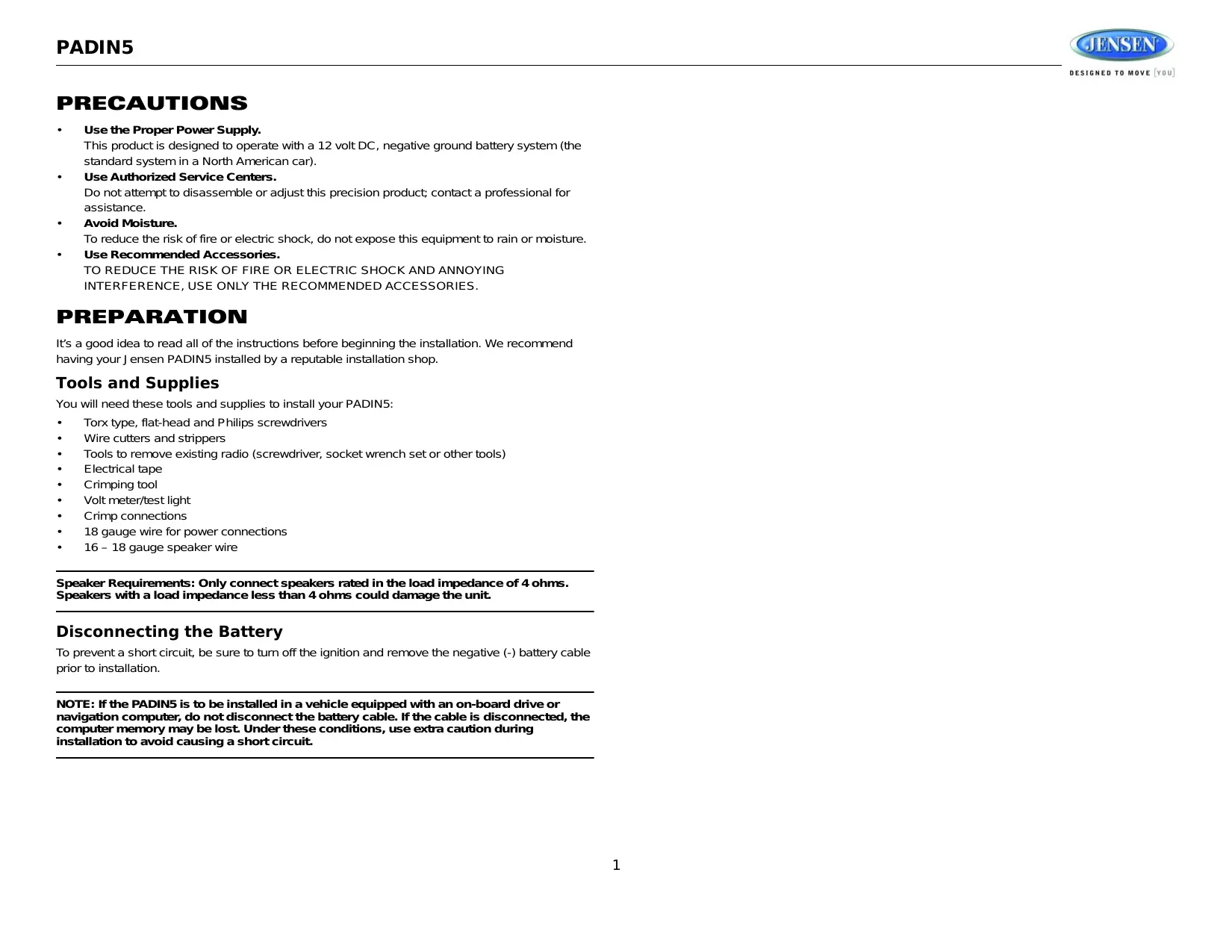
- Slide the mounting sleeve off of the chassis if it has not already been removed. If it is locked into position, use the removal keys (supplied) to disengage it.
- Check the dashboard opening size by sliding the mounting sleeve into it. If the opening is not large enough, carefully cut or file as necessary until the sleeve easily slides into the opening. Do not force the sleeve into the opening or cause it to bend or bow. Check that there will be sufficient space behind the dashboard for the radio chassis.
- Locate the series of bend tabs along the top, bottom and sides of the mounting sleeve. With the sleeve fully inserted into the dashboard opening, bend as many of the tabs outward as necessary to firmly secure the sleeve to the dashboard.
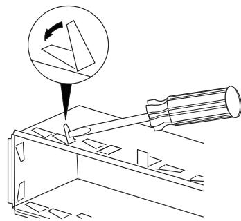
- Place the unit in front of the dashboard opening so the wiring can be brought through the mounting sleeve.
- Follow the wiring diagram carefully and make certain all connections are secure and insulated with crimp connectors or electrical tape to ensure proper operation.
- After completing the wiring connections, turn the unit on to confirm operation (vehicle ignition switch must be on). If the unit does not operate, recheck all wiring until the problem is corrected. Once proper operation is achieved, turn the ignition switch off and proceed with final mounting of the chassis.
- Carefully slide the unit into the mounting sleeve making sure it is right-side-up until it is fully seated and the spring clips lock it into place.
- Attach one end of the perforated support strap (supplied) to the screw stud on the rear of the chassis using the hex nut provided. Fasten the other end of the perforated strap to a secure part of the dashboard either above or below the radio using the screw and hex nut provided. Bend the strap, as necessary, to position it.
CAUTION: The rear of the unit must be supported with the strap to prevent damage to the dashboard from the weight of the radio or improper operation due to vibration.
- Test operation by referring to the operating instructions for the unit.
Wiring
Perform the following steps to install the radio using a wiring adapter (purchased separately):
- Splice or crimp wires.
- Attach wiring adapter to vehicle wiring harness.
- Re-connect the battery negative terminal and test radio operation to confirm correct wiring.
Rear Radio Controls and Connectors
- MICROPHONE CONNECTIONS
See "Using Microphones" on page 6.
- IR CONNECTIONS
See "AUX IR and DVD IR Connections" on page 5.
-
RADIO IN LOW/HIGH SWITCH
-
Select "LOW" when you are using low-level RCA radio input (RADIO LOW-IN).
-
Select "HIGH" when using hi-level radio input (RADIO HI-IN).
-
RCA CONNECTIONS
RADIO LOW-IN: Connect to the RCA output from your radio.
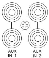
AUX IN 1 and AUX IN 2: See "AUX RCA Connections" on page 5.
AUDIO OUT: Connect to an additional amplifier.
- HIGH LEVEL WIRING CONNECTIONS
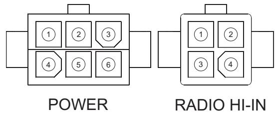
See Table 1 on page 4 for specific wiring connections.
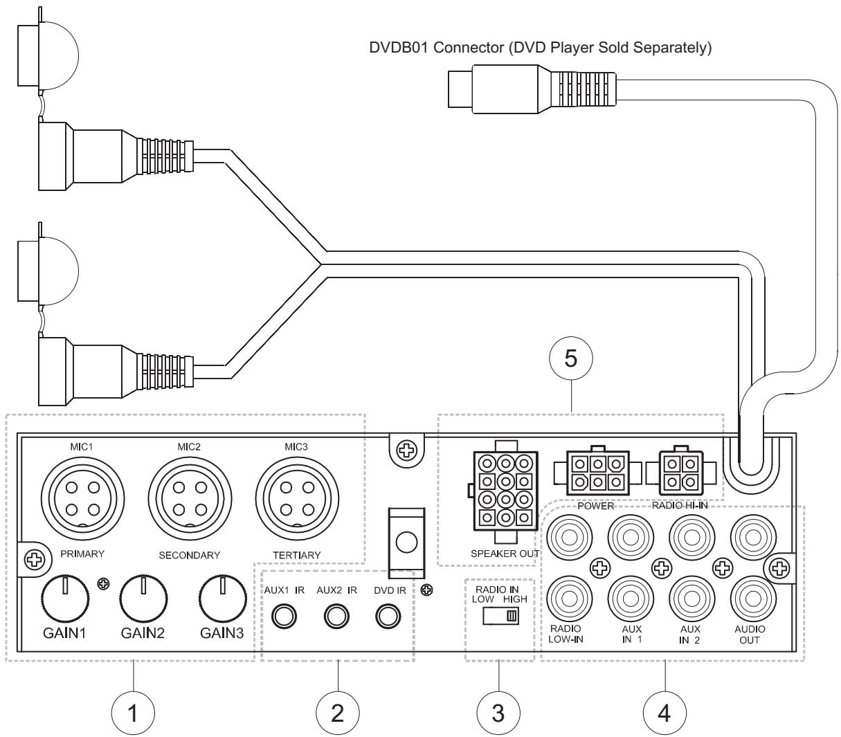
Table 1: Wiring Connections
| Pin # | Wire Color | Function |
| SPEAKER OUT | ||
| 1 | White | Driver Speaker L+ |
| 2 | Gray | Driver Speaker R+ |
| 3 | Green | Passenger Speaker L+ |
| 4 | Violet | Passenger Speaker R+ |
| 5 | White/Black | Driver Speaker L- |
| 6 | Gray/Black | Driver Speaker R- |
| 7 | Green/Black | Passenger Speaker L- |
| 8 | Violet/Black | Passenger Speaker R- |
| 9 | Orange | EXT Speaker + |
| 10 | Orange/Black | EXT Speaker - |
| 11 | White/Red | Trigger DC +12V output for AUX2 mode |
| 12 | White/Blue | Trigger DC +12V output for AUX1 mode |
| POWER | ||
| 1 | Red | DC Input: Connect to +12V switched power source. The radio will not work if this wire is not connected. |
| 2 | Pink | Trigger +12V Output for DVD mode |
| 3 | Yellow | +12V Plus Constant Power |
| 4 | Empty | Not Used |
| 5 | Blue/White | Trigger +12V Output |
| 6 | Black | Ground |
| RADIO HI-IN | ||
| 1 | White | Speaker Left + |
| 2 | Gray | Speaker Right + |
| 3 | White/Black | Speaker Left - |
| 4 | Gray/Black | Speaker Right - |
PADIN5 Connector PIN View
OPERATION
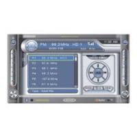
Basic Operation
Power
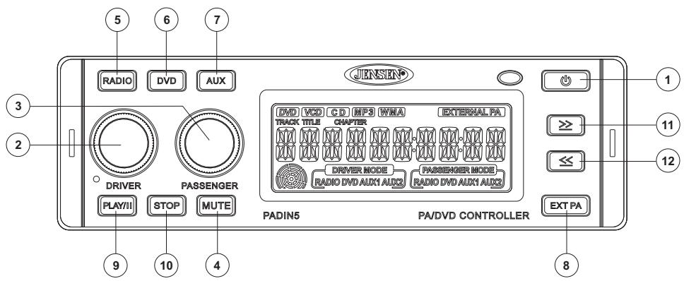
Press the POWER button (1) or any other button on the face of the unit to turn the unit on. Press POWER to turn the unit off.
Volume Control - Driver
To increase the volume for the driver, rotate the DRIVER volume control knob (2) clockwise. Rotate the DRIVER knob counter-clockwise to decrease the volume.
Volume Control - Passenger
To increase the volume for the passenger, rotate the PASSENGER volume control knob (3) clockwise. Rotate the PASSENGER knob counterclockwise to decrease the volume.
Select Driver Source
To select the Driver source, press the DRIVER volume control knob (2). The DRIVER MODE icon will flash and turn from amber to green, indicating that Driver Mode was selected. Press the RADIO, DVD or AUX button (press twice for AUX 2) to select the desired source. The selected source will be indicated on the display. To exit Driver mode, press and hold the DRIVER volume control knob for 2 seconds.
Select Passenger Source
To select the Passenger source, press the PASSENGER volume control knob (3). The PASSENGER MODE icon will flash and turn from amber to green. Select the desired source (indicated on the display). To exit Passenger mode, press and hold the PASSENGER volume control knob for 2 seconds.
Mute
Press the MUTE button (4) to silence the amplifier. Press MUTE again to resume audio.
Radio Source Button
Press the RADIO source button (5) to select radio input. The illuminated RADIO indicator will change from amber to green, indicating the selection was made.
DVD Source Button
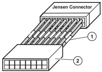
Press the DVD button (6) to play the audio from the optional DVDB01 DVD player through the selected speakers. The illuminated DVD indicator will change from amber to green, indicating the selection was made. An 8-Pin DIN connector and left and right audio input cables allow you to control the Jensen DVDB01 through the PADIN5.
NOTE: DVD audio is available for non-Jensen DVD players. To access this feature, press and hold the DVD button (6) for 2 seconds to control audio for any DVD player when the communication cable is not connected.
AUX Source Button
Press the AUX button (7) once to select AUX 1 input. To select AUX 2, press the AUX button again while in AUX 1 mode. The AUX 2 indicator on the display will change from amber to green.
AUX RCA Connections
The RCA connections for the AUX input audio channel, labeled AUX IN 1 and AUX IN 2, are located on the back of the unit.
AUX IR and DVD IR Connections
There are three 3.5mm jacks (one for AUX1, one for AUX2 and one for DVD IR) on the back of the unit in which you can plug the IR source signals. The AUX IN device can then be controlled with the AUX remote through the IR sensor on the front of the PADIN5.
AUX1 IR AUX2 IR DVD IR

NOTE: If using a wireless remote with the DVDB01, the DVDB01 wired IR connection must be plugged into the AUX1 IR, AUX2 IR or DVD IR jack.
External PA Source Button
The External PA source can be selected to broadcast the audio from a microphone. To select the External PA source, press the EXT PA button (8). The illuminated EXTERNAL PA indicator will change from amber to green, indicating the selection was made.
External Microphone Connections
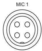
PRIMARY
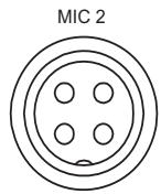
SECONDARY
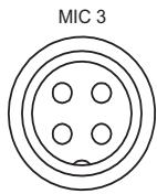
TERTIARY

GAIN 1

GAIN 2

GAIN 3
Using Microphones
There are three microphone inputs on the back of the unit labeled Primary, Secondary and Tertiary. Each microphone has its own level control located below the connector, which is used to adjust the volume level of the PA. The Primary microphone takes priority over the other two microphones. If the Secondary or Tertiary microphone is being used and the Primary microphone is keyed, only the Primary microphone audio will be heard in the PA. If the Tertiary microphone is keyed when the Secondary microphone is in use, the Secondary microphone will take priority over the Tertiary microphone (only the Secondary microphone will be heard). There are individual gain controls for each microphone on the rear of the unit. When a microphone is keyed, the audio from the Driver and Passenger modes will be muted and the audio from the microphone will be heard in the Driver, Passenger and EXT PA speakers.
Controlling the Optional DVDB01 DVD Player
NOTE: The DVDB01 is sold separately. It is not supplied with the PADIN5.
PLAY//Button
Press the PLAY/| (Play /Pause) button (9) to pause DVD play. Press PLAY/| again to resume play.
≥ Button
Press the ≥ (forward) button (11) to advance to the next chapter in a DVD or the next track on a CD.
Press and hold for 2 seconds to Fast Forward (FF) through the scene. Press and hold repeatedly to increase the FF speed from 2x , 4x , 8x , 20x and then normal play. Press the PLAY/| button (9) at any time to resume normal play.
Button
Press the ≤ (reverse) button (12) to return to the previous chapter on a DVD or the previous track on a CD.
Press and hold for 2 seconds to Rewind (RW) through the scene. Press and hold repeatedly to increase the RW speed from 2x , 4x , 8x , 20x and then normal play.
Press the PLAY/| button (9) at any time to resume normal play.
STOP Button
Press the STOP button (10) to stop DVD play. Press the PLAY/| button (9) to resume DVD play at the last scene that was displayed.
Pressing STOP again will restart the DVD at the beginning.
TROUBLESHOOTING
| Problem | Cause | Corrective Action |
| Does not operate (display does not light) | No power to yellow wire No power to red wire | Check connection with test light. Check fuse with test light. |
| Inline fuse blown | Replace fuse | |
| No power to unit | Inline fuse blown | Check/replace fuse |
| No speakers operate | Speaker harness not con- nected | Connect speaker harness. Check speaker wires. |
| Not all speakers operate | Incorrect splices or connec- tions | Check all splices and connec- tions. |
| Speaker wires shorting to chas- sis ground or to each other | Check splices and connec- tions. | |
| Blows fuses | Power wire shorting to ground | Make sure wire is not pinched. |
| Speaker wires shorting to ground | Make sure wire is not pinched. | |
| Incorrect fuse/fuse too small | Install fuse of correct rating. | |
| CD skips too much | Receiver mount is not solid or backstrap is not secure | Check mounting and back- strap and tighten if needed. |
For technical assistance, please visit www.asaelectronics.com.
SPECIFICATIONS
Power supply. 10.5-32 VDC, negative ground
Speaker output impedance 4-8 Ohms
Fuses. fast blow ATC (15 amp)
Dimensions. 7'' × 6 - 1/2'' × 2'' (178 × 165 × 51 mm)
Specifications subject to change without notice.
This device complies with Part 15 of the FCC Rules. Operation is subject to the following two conditions:
(1) This device may not cause harmful interference.
(2) This device must accept any interference received, including interference that may cause undesired operation.
NOTE: The manufacturer is not responsible for any radio or TV interference caused by unauthorized modifications to this equipment. Such modifications could void the User's authority to operate the equipment.
LIMITED WARRANTY
90 Day / 12 Month Limited Warranty
AUDIOVOX SPECIALIZED APPLICATIONS, LLC (the Company) warrants to the original retail purchaser of this product that should this product or any part thereof, under normal use and conditions, be proven defective in material or workmanship within 90 days from the date of original purchase, such defect(s) will be repaired or replaced (at the Company's option) without charge for parts and repair labor. After the initial 90 day period and for a period of 12 months from the date of the original purchase, the Company will supply at no charge a replacement for any defective part(s).
To obtain repair or replacement within the terms of this warranty, the end user should contact the O.E.M. The product is to be delivered to the OEM or original place of purchase, with proof of warranty coverage (e.g. dated bill of sale, and serial number of the unit, and vin#), specification of defect(s), transportation prepaid, to an approved warranty station. This warranty does not extend to the elimination of externally generated static or noise, to the correction of antenna problems, to costs incurred for removal or reinstallation of the product, or to damage to any tapes, CD's, DVD's, speakers, accessories, or electrical systems. This warranty does not apply to any product or part thereof which, in the opinion of the Company, has been damaged through alteration, improper installation, mishandling, misuse, neglect, or accident. THE EXTENT OF THE COMPANY'S LIABILITY UNDER THIS WARRANTY IS LIMITED TO THE REPAIR OR REPLACEMENT PROVIDED ABOVE, AND, IN NO EVENT, SHALL THE COMPANY'S LIABILITY EXCEED THE PURCHASE PRICE PAID BY THE PURCHASER FOR THE PRODUCT.
This warranty is in lieu of all other express warranties or liabilities. ANY IMPLIED WARRANTY, INCLUDING ANY IMPLIED WARRANTY OF MERCHANTABILITY, SHALL BE LIMITED TO THE DURATION OF THIS WARRANTY. ANY ACTION FOR BREECH OF ANY WARRANTY HEREUNDER INCLUDING ANY IMPLIED WARRANTY OF MERCHANTABILITY MUST BE BROUGHT WITHIN A PERIOD OF 30 DAYS FROM THE DATE OF ORIGINAL PURCHASE. IN NO CASE SHALL THE COMPANY BE LIABLE FOR ANY CONSEQUENTIAL OR INCIDENTAL DAMAGES FOR BREECH OF THIS OR ANY OTHER WARRANTY, EXPRESS OR IMPLIED WHATSOEVER. No person or representative is authorized to assume for the Company any liability other that expressed herein in connection with the sale of this product.
Some states do not allow limitations on how long an implied warranty lasts or the exclusion or limitation of incidental or consequential damages so the above limitations or exclusions may not apply to you. This warranty gives you specific legal rights and you may also have other rights which vary from state to state.
PRECAUTIONS
Alimentation. 10.5-32 VDC, negative ground
ASA Electronics Corporation
www.asaelectronics.com
www.jensenrvdirect.com
© 2009 ASA Electronics Corporation
v.083009