
AV3850 - To scan AVISION - Free user manual and instructions
Find the device manual for free AV3850 AVISION in PDF.
User questions about AV3850 AVISION
0 question about this device. Answer the ones you know or ask your own.
Ask a new question about this device
Download the instructions for your To scan in PDF format for free! Find your manual AV3850 - AVISION and take your electronic device back in hand. On this page are published all the documents necessary for the use of your device. AV3850 by AVISION.
USER MANUAL AV3850 AVISION
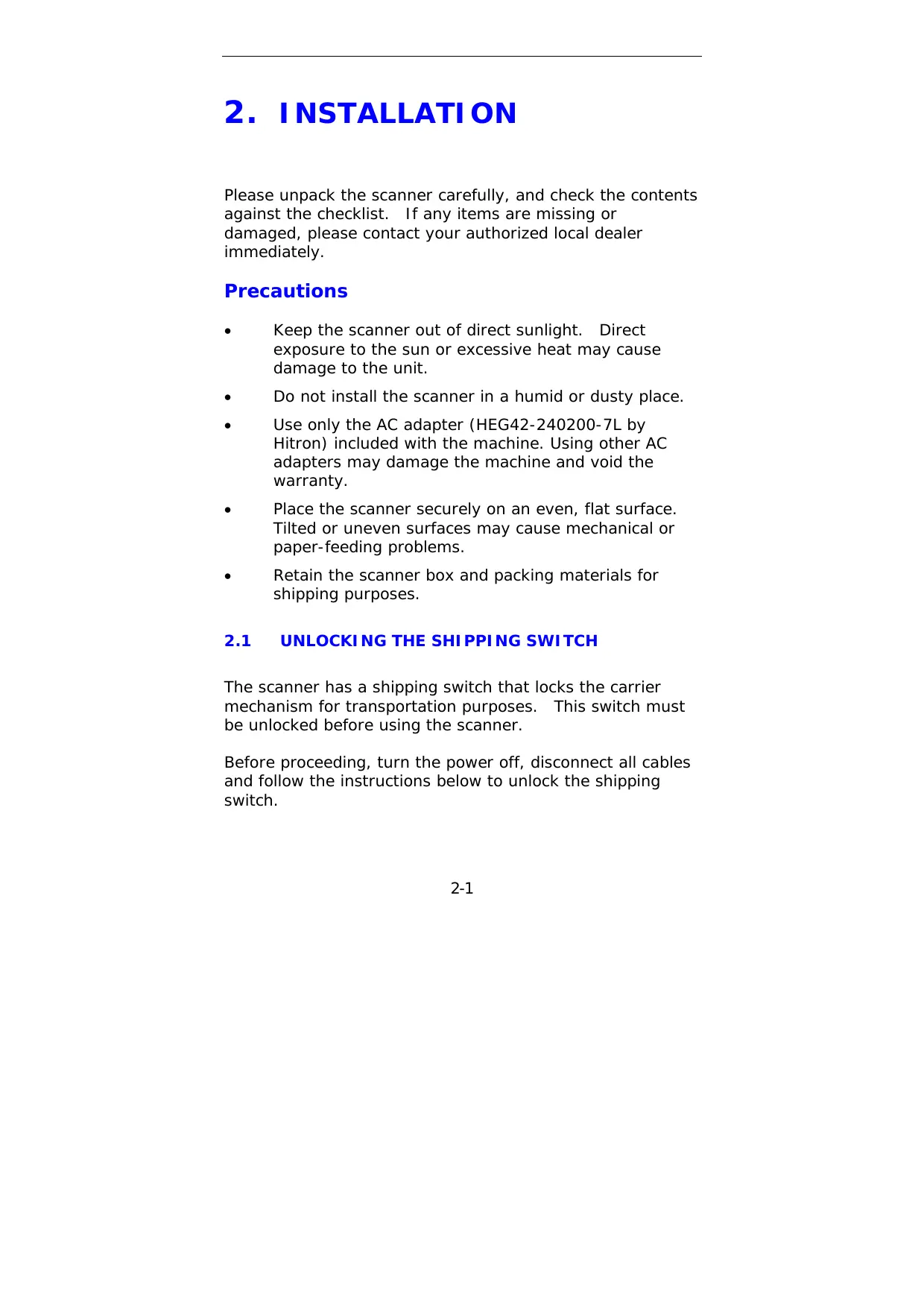
High Speed Document Scanner
User's Manual
Regulatory model: 300500001/300500002
FCC Radio Frequency Interference Statement
This equipment has been tested and found to comply with the limits for a class B digital device, pursuant to Part 15 of the FCC rules. These limits are designed to provide reasonable protection against harmful interference in a residential installation. This equipment generates, uses, and can radiate radio frequency energy and, if not installed and used in accordance with the instruction manual, may cause harmful interference to radio communication. However, there is no guarantee that interference will not occur in a particular installation. If this equipment does cause harmful interference to radio or television reception, which can be determined by turning the equipment off and on, the user is encouraged to try to correct the interference by one or more of the following measures:
- Reorient or relocate the receiving antenna.
- Increase the separation between the equipment and receiver.
- Connect the equipment into an outlet on a circuit different from that to which the receiver is connected.
- Consult the dealer or an experienced radio/TV technician for help.
CAUTION: Any changes or modifications not expressly approved by the manufacture of this device could void the user's authority to operate the equipment.
Table of Contents
1. INTRODUCTION 1-1
2. INSTALLATION 2-1
2.1 UNLOCKING THE SHIPPING SWITCH 2-1
2.1.1 UNLOCKING THE SCANNER 2-2
2.1.2 LOCKING THE SHIPPING SWITCH 2-3
2.2 SCSI ID 2-4
2.3 USB INTERFACE 2-6
2.4 ADF PAPER CHUTE 2-6
2.5 ADF OUTPUT TRAY 2-7
2.6 DOCUMENT LOADING 2-8
2.7 ADF SCANNING 2-9
2.8 CONNECTING THE CABLE 2-10
3. REQUIREMENTS & SOFTWARE INSTALLATION .3-1
3.1 SCANNER DRIVER INSTALLATION 3-1
3.2 SCANNING WITH IMAGE EDITING SOFTWARE.... 3-1
3.2.1 A GLANCE OF THE SCANNER
PROPERTIES Dialog Box 3-3
4. USING THE SCANNER PROPERTIES Dialog Box... 4-1
4.1 BUTTONS ON THE SCANNER PROPERTIES Dialog Box 4-2
4.2 THE IMAGE TAB. 4-4
4.2.1 THE IMAGE SELECTION BOX 4-5
4.2.2 OTHER IMAGE OPTIONS 4-7
4.2.3 SCANNING COLOR IMAGES.. 4-14
4.2.4 SCANNING GRYSCALE IMAGES 4-14
4.2.5 SCANNING B&W IMAGES.. 4-14
4.3 THE COMPRESSION TAB 4-15
4.4 THE COLOR DROPOUT TAB 4-17
4.4.1 COLOR DROPOUT SELECTION 4-17
4.4.2 OTHER COLOR DROPOUT OPTIONS ....4-18
4.5 THE PAPER TAB. 4-20
4.5.1 CROPPING 4-21
4.5.2 OTHER PAPER SELECTION. 4-24
4.6 THE OPTIONS TAB. 4-28
4.7 THE SETTING TAB 4-34
4.8 THE INFORMATION TAB 4-36
5. ISIS INTERFACE OPERATION 5-1
6. MAINTAINENCE 6-1
6.1 CLEANING THE ADF 6-1
6.2 CLEANING THE GLASS 6-3
6.3 REPLACING THE ADF SNAP-IN PAD MODULE 6-4
6.4 REPLACING THE ADF PAPER FEED ROLLER 6-6
7. TROUBLE SHOOTING 7-1
7.1 QUESTION AND ANSWER 7-1
7.2 PAPER JAM IN THE ADF 7-5
8. TECHNICAL SERVICE 8-1
9. SPECIFICATIONS 9-1
Index
1. INTRODUCTION
Congratulations on your purchase of the document scanner.
Before you install and operate the scanner, please take a few minutes to read through this manual. It provides you with the proper instructions on how to unpack, install, operate and maintain the scanner.
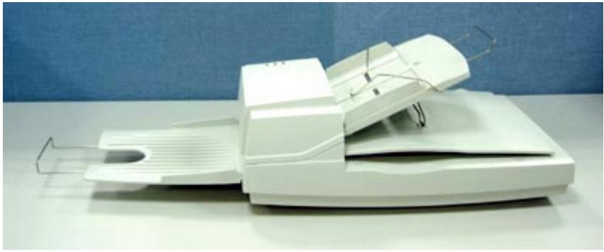
Figure 1-1 shows how the scanner is packed. You can check all items against your "checklist", included with your scanner.
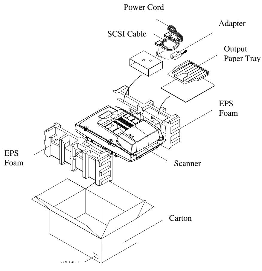
Figure 1-1 Scanner Packing
2. INSTALLATION
Please unpack the scanner carefully, and check the contents against the checklist. If any items are missing or damaged, please contact your authorized local dealer immediately.
Precautions
- Keep the scanner out of direct sunlight. Direct exposure to the sun or excessive heat may cause damage to the unit.
- Do not install the scanner in a humid or dusty place.
- Use only the AC adapter (HEG42-240200-7L by Hitron) included with the machine. Using other AC adapters may damage the machine and void the warranty.
- Place the scanner securely on an even, flat surface. Tilted or uneven surfaces may cause mechanical or paper-feeding problems.
- Retain the scanner box and packing materials for shipping purposes.
2.1 UNLOCKING THE SHIPPING SWITCH
The scanner has a shipping switch that locks the carrier mechanism for transportation purposes. This switch must be unlocked before using the scanner.
Before proceeding, turn the power off, disconnect all cables and follow the instructions below to unlock the shipping switch.
2.1.1 UNLOCKING THE SCANNER
i). Carefully place the scanner in an upright position on its front.
ii). Unlock the scanner by moving the lock switch beneath the scanner to the "Unlock" position (See Figure 2-1).
iii). Gently place the scanner back to its normal position.
Figure 2-1 Unlocking the Shipping Switch
2.1.2 LOCKING THE SHIPPING SWITCH
Whenever you need to move the scanner to a new location it is advisable to lock the shipping switch to avoid causing damage to the scanners' internal mechanism. Please follow the instructions below to lock the shipping switch.
1). Turn off the scanner.
2). Lift the Document cover to reveal the flatbed glass and scanning unit.
3). Turn on the scanner.
4). Turn off the scanner again while the scanning unit moved to the end for a few seconds.
5). Place your scanner in an upright position on its front side.
6). Lock your scanner by moving the lock switch to the "Locked position".
7). Place the scanner back to its normal position.
2.2 SCSI ID
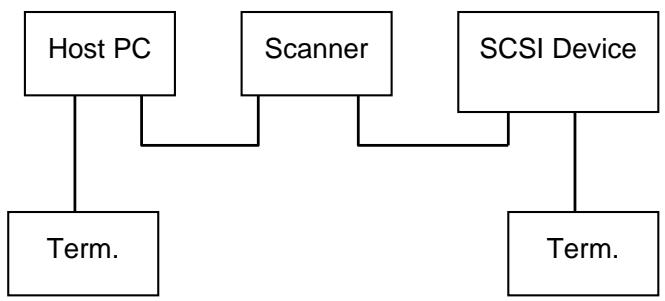
When you have several devices on a SCSI chain, you may need to adjust the SCSI ID selector setting located on the back of the scanner. This setting assigns a specific "device ID" to the scanner. If the assignment conflicts with an existing SCSI device, please select a new ID. (See Figure 2-2)
Note: The factory setting for scanner is ID 6. Usually, ID 0 is assigned to an internal hard disk drive, and ID 7, ID 8, and ID 9 are not in actual use.
Using a suitable tool, turn the selector switch until the arrow points to the desired ID number.
2.3 Setting SCSI Terminator
The scanner is equipped with a built-in terminator switch on the rear of the scanner. (See Figure 2-2). The scanner is equipped with a built-in terminator switch on the rear of the scanner. Turn the terminator switch on if the scanner is to be connected to the computer as the only or the last SCSI device. Turn the terminator switch off if the scanner is to be located between the computer and the other SCSI device.
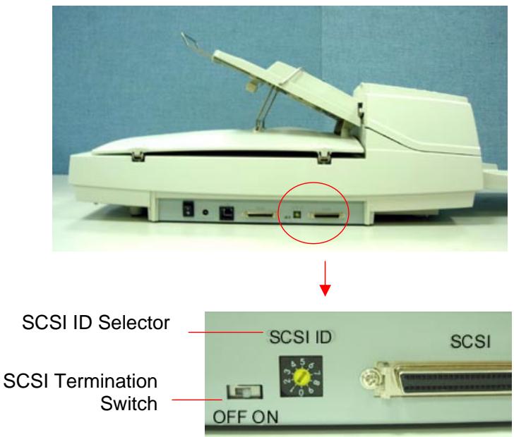
Figure 2-2 Adjusting the SCSI ID setting
2.3 USB INTERFACE
Note that the machine is designed with two ports, SCSI and USB, to connect with the computer. If you are using the USB port, be sure to install the scanner driver before connecting the USB cable to your computer. Otherwise, the scanner may not work properly.
2.4 ADF PAPER CHUTE
i). Lift the paper chute to about 45 degrees.
ii). Pull the paper-chute wire leg down to the grips on the document cover.
iii). Slightly press the paper chute to snap the wire leg into the grips on the document cover.
iv). Pull out the paper chute extension to the length you want.
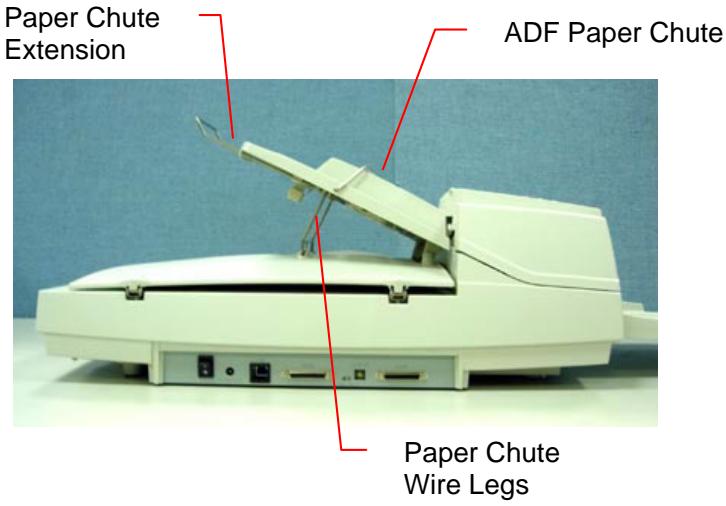
Figure 2-3 Setting the ADF
2.5 ADF OUTPUT TRAY
i). Hold the output paper tray some 30 degrees aslant as shown in Figure 2-4.
ii). Insert the three protrusions on the output paper tray to the three slots on the ADF.
iii). Release the paper tray gently. Make sure the tray is firmly attached to the ADF.
iv). Pull out the output paper tray extension wire to the desired length.
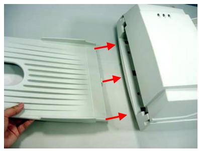
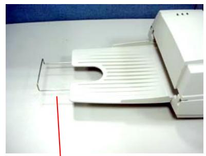
Output Tray Extension Wire
Figure 2-4 Install the ADF Output Paper Tray
2.6 DOCUMENT LOADING
For flatbed scanning
Documents that can not be scanned using the ADF can be placed on the flatbed for scanning. (See Figure 2-5)
i). Place the document to be scanned onto the document glass face down.
ii). Position the document so that the upper-right corner is aligned with the reference mark.
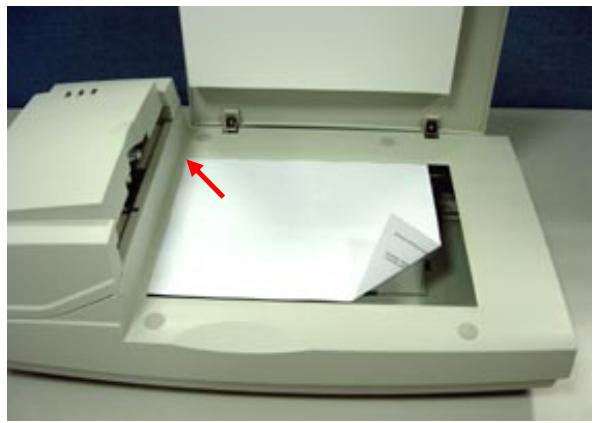
Figure 2-5 Place Document on the scanner
2.7 ADF SCANNING
Multiple documents can be fed automatically using the ADF. Refer to Figure 2-6.
i). To prevent occasional paper jam when automatically feeding multiple documents, fan the paper before loading.
ii). Lift the balance wire.
iii). Place the documents onto the ADF paper chute in either paper side (face-down, face-up), with the leading edge in the auto feeder entrance.
Let the balance wire rest on the top of the documents.
iv). Adjust the left and right guides so that they are snug against the sides of the documents.
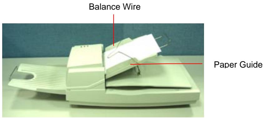
Figure 2-6 Loading Multiple Document
2.8 CONNECTING THE CABLE
i). Turning the Power Off
Depress the side marked "O" to turn the power off.
Connect the power cable and SCSI signal cable as shown in Figure 2-7.
ii). Turning the Power On
Depress the side marked "I" to turn the power on. The POWER LED will light. If not, please check the power source.
iii). SCSI Termination/USB Port
The scanner is designed with both the USB and SCSI port. If you wish to connect the scanner with a USB port, please install the scanner driver first and then connect the USB cable. If you wish to connect the scanner with SCSI port, please note the following:
The scanner comes complete with a built in SCSI terminator. If the scanner is the last device in a SCSI chain, the terminator should be switched on. If the scanner is not the last device, the terminator should be off. The terminator on/off switch is located on the back of the scanner, to the left of the SCSI cable connectors.
(Terminator Off)
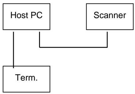
(Terminator On)
Figure 2-2 Terminator ON/OFF
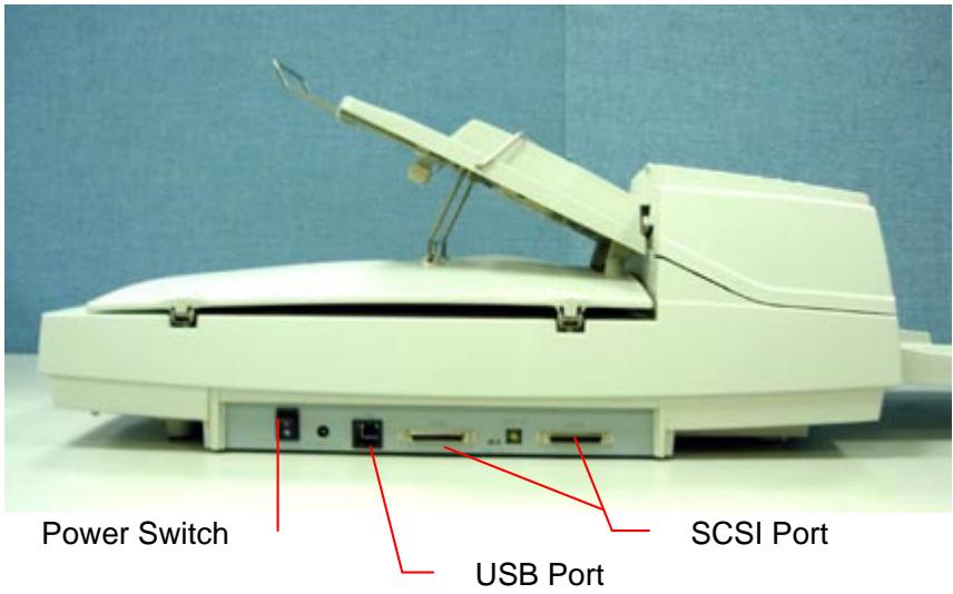
Figure 2-7 Cable Connection
3. REQUIREMENTS &
SOFTWARE
INSTALLATION
To run the scanner at rated speed recommended, you must have the following minimum requirements:
IBM compatible PC 586, Pentium or higher
- Microsoft Windows 95 /NT/98/98SE/Me/2000/XP
One SCSI card installed on your computer; or a USB port on your computer
100M bytes of available hard disk space for installation;
128M bytes of RAM
- A CD-ROM drive.
3.1 SCANNER DRIVER INSTALLATION
Important!
If you wish to connect the scanner with a USB port, please install the scanner driver first and then connect the USB cable.
- Start your PC and Windows application.
- Insert the scanner bundled CD to your CD-ROM drive.
- The software installation graphic should appear as below:

If not, press the Start button, choose RUN,and type d:\driver\twain driver (or ISIS driver)\setup.exe (d means the letter indicating your current CD-ROM drive). Click on the OK button.
- Follow the subsequent instructions on the screen to complete the driver and application installation.
3.2 SCANNING WITH IMAGE EDITING SOFTWARE
The scanner driver is not a stand-alone program, it has to be started from within a TWAIN-compliant or plug-in software application and then the scanner driver is able to scan and load the image to your computer.
The command to start the scanner driver may vary due to different software applications.
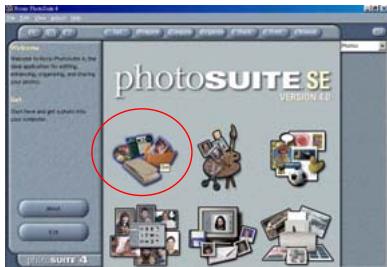
- Start a TWAIN compliant software application such as Roxio PhotoSuite which is bundled in the CD.
- Click Get>Scanner (TWAIN).
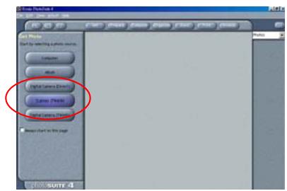
- Choose the scanner model as your scanning source. (You only need to do this once.)
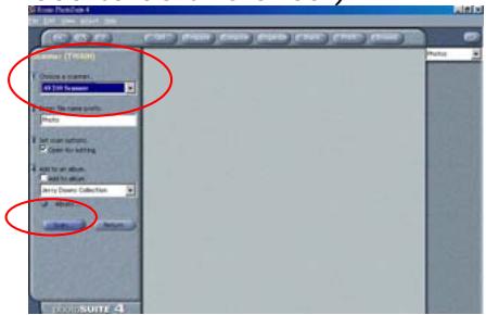
- Place the document FACE DOWN on the document glass.
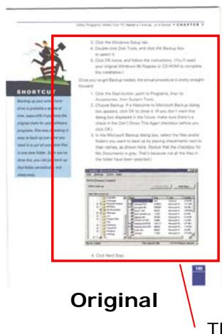
- Click the Scan button to prompt the Scanner Properties Dialog Box.
-
Choose your image type and the side of document you wish to scan from the Image Selection box. Click the Scan button to scan the document.
-
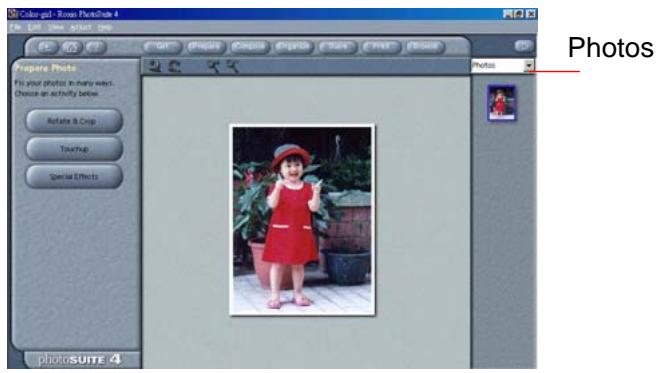
Click Exit to return to the main screen and click Open Library and Photos at the upper-right corner to open your scanned image.
Image Selection Box
3.2.1 A GLANCE OF THE SCANNER PROPERTIES DIALOG BOX
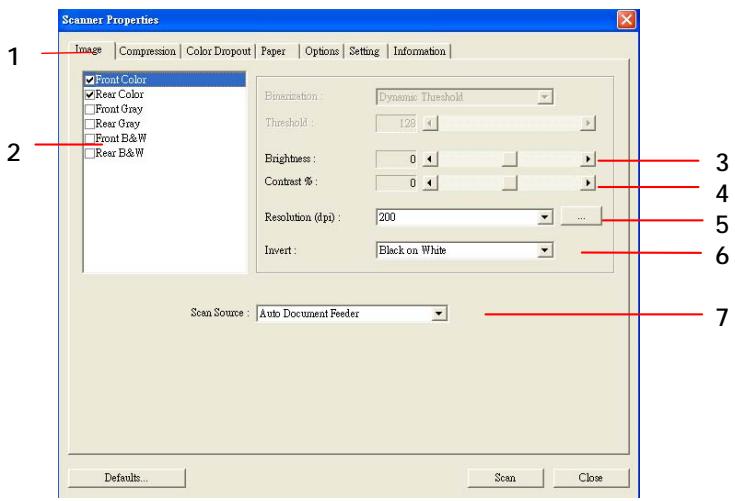
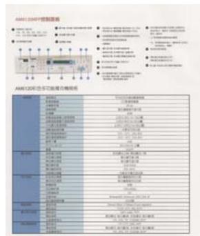
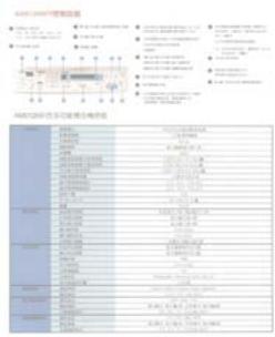
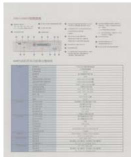
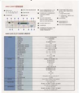
| 1. Tab Options | Choice: Image, Compression, Color Dropout, Paper, Options, Settings, Information. |
| 2. Image Selection Box | Choose your image type and the side of document you wish to scan. Options vary based on type of scanner. |
| 3. Brightness: | Adjust the brightness level from -100 to +100. |
| 4. Contrast | Adjust the contrast level from -100 to +100. |
| 5. Resolution | Determine the quality of the scanned image. The industry standard is 200 dpi. |
| 6. Invert | Reverse the color of your scanned image. |
| 7. Scan Source | Choice: Auto Document Feeder, Flatbed, Flatbed (Book), Automatic (This option varies based on type of scanner.) |
| 8. Defaults | Reset all values on the tabs to the factory default settings. |
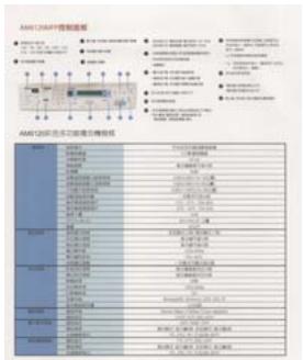
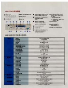
4. USING THE SCANNER PROPERTIES Dialog Box
The Scanner Properties dialog box allows you to configure the scanner's settings. It consists of several tabbed windows each of which will be described in this chapter.

The Scanner Properties dialog box
4.1 BUTTONS ON THE SCANNER PROPERTIES DIALOG BOX
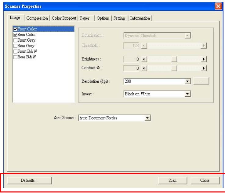
The buttons on the Scanner Properties dialog box
| Buttons | Description |
| Defaults | Click the Defaults button, the factory default settings will be shown on each tab. |
| Scan | After all the scan settings are satisfactory, click the Scan button to start scanning your document. |
| Close | Click the Close button to leave the Scanner Properties dialog box. |
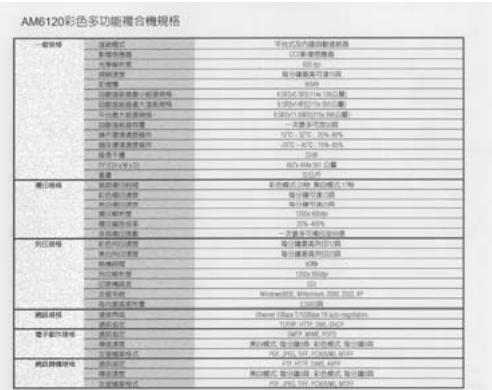
The following table shows the default settings :
| Tab name | Default settings |
| Image | Image: Front B&W Binarization: Dynamic Threshold Resolution: 200 dpi Invert: Blank on White Scan Source: Auto Document Feeder Threshold: None Brightness: None Contrast: None |
| Compression | None |
| Color Dropout | None |
| Paper | Cropping: Automatic Deskew: Yes Orientation: Portrait OverScan: 0.00 Multifeed Detection: None Unit: Inch |
| Options | Flip Side Rotation: Book Rotation Degrees: None Blank Page Removal: None Edge Fill: White, 0 mm Image Control Option: None |
| Setting | Enable Energy Saver: Enable, 15 minutes after last scan action Show Scanning Progress: Yes Show Warning Message: Yes Save Settings after Closing: Yes |
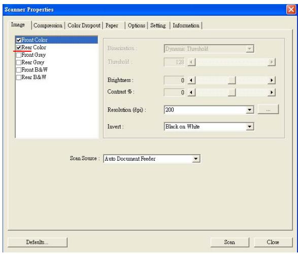
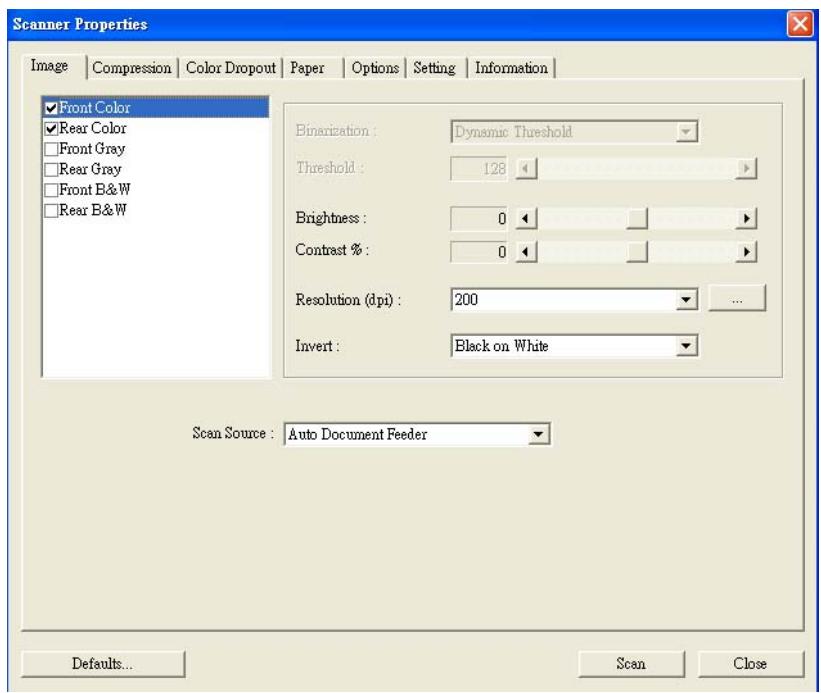
4.2 THE IMAGE TAB
The Image tab allows you to choose the front side and (or) the rear side of your document, the type of image, and to set several basic scan settings. Note that except for the resolution, you can set individual scan settings for the front side and the rear side. For example, all settings in the Image tab, Compression tab, Color Dropout tab can be set individually for the front and the rear side. However, the settings in the Paper tab, the Option tab, and the Setting tab have to be set the same for the front and rear side.
The Image tab dialog box
4.2.1 THE IMAGE SELECTION BOX
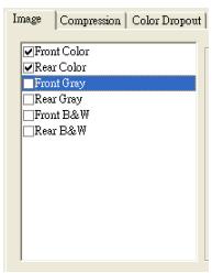
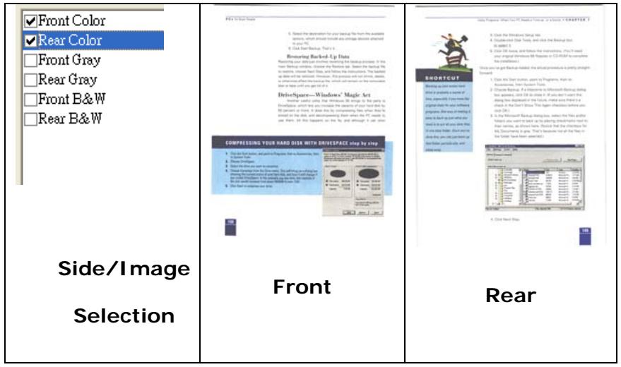
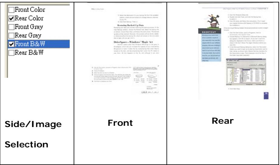
The Image Selection box includes the image type and document side option. If you wish to scan both the front side and the rear side of your color document, you can check both Front Color and Rear Color at the same time. Note the options vary based on type of scanner.
Example 1: Scanning a two-sided color document, both sides in color
Example 2: Scanning a two-sided color document, one in B&W(Drop Blue Color : Threshold : 10, Background : 79), the other in color
| Image Type | Description |
| Color | Choose Color if you wish to scan a color image for your original in color. |
| Gray | Choose Gray image if your original contains actual shades of gray. |
| B&W | Choose B&W if your original contains only text, pencil or ink sketch. |

B&W

Gray
Color
4.2.2 OTHER IMAGE OPTIONS
Binarization
This is the process of converting a grayscale or color image to a bi-tonal image. There are several different methods of performing this conversion. Two of the options are Dynamic Threshold and Fixed Processing.
Dynamic Threshold: Selecting Dynamic Threshold allows the scanner to dynamically evaluate each document to determine the optimal threshold value to produce the highest quality image. This is used to scan mixed document containing faint text, shaded background, or color background with a single setting. If Dynamic Threshold is selected, Threshold, Brightness, and Contrast are not available.
Fixed Processing: Used for black-and-white and other high contrast documents. A single level is set to determine the black-and-white transition. The threshold is programmable over the entire density range. Fixed Processing sets Contrast to 0. If Fixed Processing is selected, Contrast is not available.
Threshold
Used to convert a grayscale image to a bi-tonal image. The value ranges from 0 to 255. A low threshold value produces a lighter image, and can be used to subdue backgrounds and subtle, unneeded
information. A high threshold value produces a darker image, and can be used to help pick up faint images.
Adjust the threshold setting by dragging the Threshold sliding bar to the left or right to achieve the desired threshold setting.
200 dpi,
Threshold:80,
Brightness: 0
200 dpi,
Threshold:170,
Brightness: 0
Brightness
Adjusts the lightness or darkness of an image. The higher the value, the brighter the image. Drag the slider to the right or left to increase or decrease the brightness. The range is from -100 to +100 .
Contrast
Adjusts the range between the darkest and the lightest shades in the image. The higher the contrast, the bigger the different grayscale. Drag the slider to the right or left to increase or decrease the contrast. The range is from -100 to +100.
Brightness: -50
Brightness: 0 (Normal)
Brightness: +50
Contrast: -50
Contrast: 0
Contrast: +50
Resolution
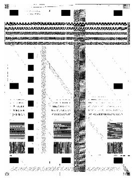
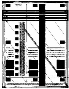
A good control of the resolution results a good detail of an image that scans. The resolution is measured by dots per inch (dpi). Normally, the greater the dpi number, the higher the resolution and the image file size. Be aware that greater resolution takes more time to scan, and more disk space for the scanning image. For your information, an A4 size color image scanned at 300 dpi at True Color mode consumes approximately 25 MB of disk space. A higher resolution (usually means over 600 dpi) is only recommended when you need to scan a small area at True Color mode.
Choose a resolution value from the drop down list. The default value is 200 dpi. Available resolutions are 75, 100, 150, 200,300, 400 and 600. Or you may choose your desired value by clicking the box in the right side of the drop down list and press the arrow key to select your desired value and then click the Add button to include it in the drop down list.

Resolution: 75 dpi

Resolution: 150 dpi
Invert Reverses the brightness and the colors in the image. The default setting is Black on a White background. Reverse mode is White on a Black background. For color images, each pixel will be changed into its complementary color at the command of Invert.
"I am not worthy to have you enter my
e that is God, I beg all my brothers - those we who work manually, clerics and lay brothers. ards being humble in all things; not to glorify r to become interforly proud because of good w sometimes says or does in them or through tord: Do not rejoice...in the fact that the de : 10:20) Let us be firmly convinced of the fact
Black on White
"I am not worthy to have you enter my
that is God, I beg all my brothers - those who work manually, clerics and lay brothers. rds being humble in all things; not to glorify to become Interiorly proud because of good. sometimes says or does in them or through urd: Do not rejoice... in the fact that the de 10:20) Let us be firmly convinced of the fact
White on Black
Scan Choice:
Source
- Auto Document Feeder: Used to scan multiple pages.
- Flatbed: Used to scan a single page. For example, pages from newspaper clipping, paper with wrinkles or curls.
- Flatbed (book): Used to scan several inside pages from book.
Automatic: Allow the scanner automatically set its scan source. If Automatic is selected and there is document in both the auto document feeder (ADF) and the flatbed, then the scan source will be automatically set to ADF. If Automatic is selected and there is document only in flatbed, then the scan source will be set to flatbed.
Note the options vary based on type of scanner.
4.2.3 SCANNING COLOR IMAGES
The following options are available for scanning color images.
Brightness
- Contrast
Resolution
Invert
4.2.4 SCANNING GRYSCALE IMAGES
The following options are available for scanning gray images.
Brightness
- Contrast
Resolution
Invert
4.2.5 SCANNING B&W IMAGES
The following options are available for scanning B&W images.
- Binarization (Dynamic Threshold)
Resolution
Invert
Or
- Binarization (Fix Processing)
Threshold
Brightness
Resolution
Invert
4.3 THE COMPRESSION TAB
The Compression tab allows you to compress your scanned image and choose the level of compression. Bitonal images are normally compressed using CCITT standard called Group 4 (G4). Color and grayscale images are often compressed using JPEG technology. Move the JPEG Quality slider to the right or left to increase or decrease the level of compression. Note the greater the compression level, the lower image quality. Default is 50% .
Note that the compression depends on your image editing application. If your image editing application does not support the type of compression format, then either a warning message will appear or the image quality of the compressed file will not be acceptable.
JPEG (Joint Photographic Editor Group). This group developed and lent their name to a file compression standard for color and grayscale images that is widely used by scanners, and software applications. On Microsoft Windows-based systems, a file with the extension .jpg has normally been compressed using this standard.
For scanning color or gray images, the following compressions are available:
None
JPEG
For scanning B&W images, the following compressions are available:
None
G4
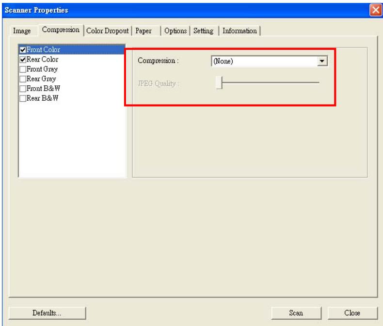
The Compression tab dialog box
4.4 THE COLOR DROPOUT TAB
4.4.1 COLOR DROPOUT SELECTION
Color Dropout tab allows you to drop either of the red, blue, or green color in your scanned image. If your image contains red color watermark or background, choose the R (Red) channel then any red watermark or background will be removed. This feature is used to sharpen your text when using OCR (Optical Character Recognition) software.
Note that this function supports only black & white and gray images. Therefore, be sure to choose any black & white or gray image type while applying this function.
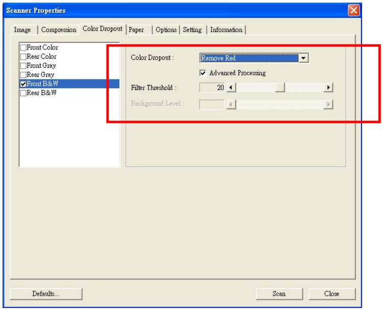
The Color Dropout dialog box
4.4.2 OTHER COLOR DROPOUT OPTIONS
Advanced Processing provides two options that can adjust your scanned image in the best optimal result.
Filter
Threshold
This value is used to determine the color which will be dropped out. A lower value will drop more of the selected color out, while a higher value will leave more of the selected color in.
Background
Level
The pixel which is higher than the background value will be adjusted to the lightest point. Adjust the value for both the Filter Threshold and Background Level to produce the best optimal result.
Example, slightly adjusting the background value makes your text more clear.
Original
Remove Blue, Threshold: 20, Background: 255
Remove Blue, Threshold: 20, Background Level: 210
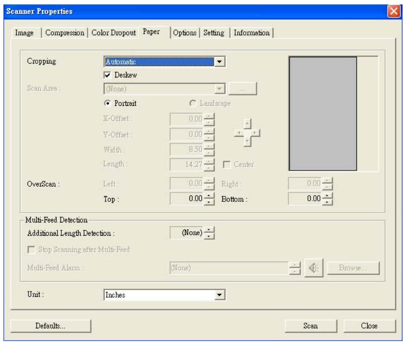
4.5 THE PAPER TAB
The Paper tab allows you to define values relating to image output (i.e., Auto Crop or not, Scan Area, OverScan, Multi-Feed Detection).
The Paper tab dialog box
4.5.1 CROPPING
Cropping allows you to capture a portion of the document being scanned. Choice: Automatic, Fixed to Transport, EOP (End of Page) Detection.
| Options | Description |
| Automatic | Automatic adjusts the cropping window according to different document sizes. Use this option for batches of mixed-sized documents. |
| Fixed to Transport | This feature allows you to define the area or zone to be imaged. Use for batches of same-sized documents. If you select this option, you can use the arrow keys to define the x and y offset values, width and length to redefine your scanned area. The Display window will show image placement as you change the values. |
| EOP (End of Page) Detection | This feature allows you to define the area or zone to be imaged. Use for batches of same-width but different length documents. If you select this option, you can use the arrow keys to define the x and y offset values, width and length to redefine your scanned area. The Display window will show image placement as you change the values. |
The following options are only available when Fixed to Transport is selected.
X-Offset — the distance from the left end of the scanner to the left edge of the scanning area.
- Y-Offset — the position from the top end of the document to the top end of the scanning area.
- Width — the width of the scanning area.
Length - the length of the scanning area.
- Center: automatically calculates the x-offset for center-fed feeding based upon document size selected.

- — relocate the scan area by click the arrow key on the cross sign while retain the scan size. View the result from the Display window.
Example: Redefine your scan area ( x-offset: 2.25 inches ; y-offset:1.13 inches)
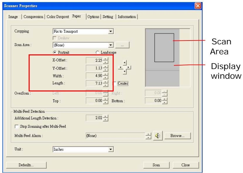
After Fixed to Transport
4.5.2 OTHER PAPER SELECTION
Deskew
Use this option to automatically deskew a document.
Note: If the skew angle is too great, some of the image may be cut off.
Scan Area
Choose your desired paper size with the drop-down list box. Or you may select a custom paper size by clicking the Scan Area box and then click Add to include in the choice.
Choice: None, US Letter- 8.5'' x 11", US Lega - 8.5'' x 14", ISO A4 - 21 x 29.7 cm, ISO A5 - 14.8 x 21 cm, ISO A6 - 10.5 x 14.8cm, ISO A7 - 7.4 x 10/5 cm, ISO B5 - 17.6 x 25 cm, ISO B6 - 12.5 x 17.6 cm, ISO B7 - 8.8 x 12.5 cm, JIS B5 - 18.2 x 25.7 cm, JIS B6 - 12.8 x 18.2 cm, JIS B7 - 9.1 x 12.8 cm, Scanner Maximum.
OverScan
Overscan allows you to add a specific margin at top and bottom or right and left (Options vary based on the type of scanner) of the edge of the image. This is used to reduce possible corner clipping on the skewed images and often applied to a batch of skewed document to be scanned in the auto document feeder. Select a value between 0 and +5 mm. Note the overscan result will not be shown in the Display window and that the availability of the function varies based on type of scanner.
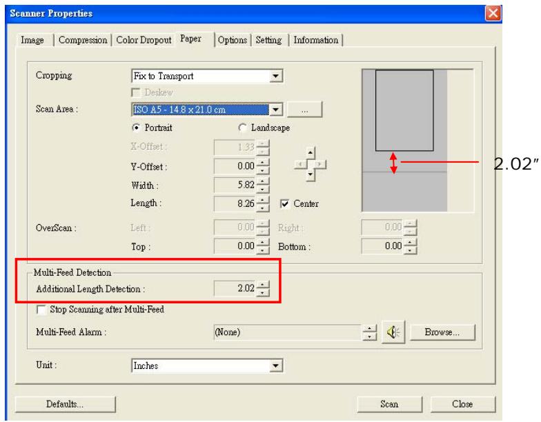
Multi-Feed Detection
Multi-Feed Detection allows you to detect overlapped document that go through the auto document feeder. Multi-Feed usually occurs due to stapled documents, adhesives on documents, or electro-statically charged document. Note : The availability of the function varies based on type of scanner.
Additional Length Detection
Additional Length Detection allows you to define the length of document being multi-fed. This value indicates the additional length exceeding your scan area. The Display window will show the size of the document as you change the value. A value of 0 indicates no additional length detection. The Additional Length Detection is best used when scanning same-size documents in the auto document feeder.
Example : Additional Length Detection : Set Additional Length to be 2.02 inches
There are three options available if Multi-Feed is detected.
- Stop Scanning after Multi-Feed
If this is selected, the scanner will stop the feeder if multi-feed is detected.
Multi-Feed Alarm:
If this is selected and a wave file is added, the scanner will produce a sound alarm if multi-feed is detected.
How to add the sound alarm :
- Click the Browse button on the right side of the speaker icon. The Open dialog box appears.
- Choose your wave file.
- Click the Open button. The wave file is added.
Units
Defines the primary measurement system. Inches, Millimeters, and Pixels are available.
4.6 THE OPTIONS TAB
The Options tab allows you to set following additional image processing settings.
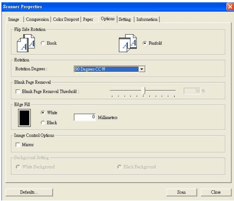
The Option tab dialog box
Flip Side Rotation
This option allows you to select the orientation of the double-sided documents been fed and if "fanfold" is selected, the image of the reverse side will be rotated to 180 degrees.
This is applied to double-sided documents which are viewed in portrait (height is greater than width) but are sometime fed into the scanner in landscape (width is greater than height) or vice versa. In this case, the image of the reverse side has to be rotated additional 180 degrees.
Choice: Book, Fanfold.
If "Book" is selected, the image of the reverse side will not be rotated.
The following illustration shows the orientation of the document which should be viewed in portrait but is fed into the scanner in landscape
Rotate Image
Choose the rotation angle from the drop down list if you wish to rotate your scanned image.
Choice: None, 90^ CW(clockwise), 90^ CCW(counter clockwise), 180^ .
123


Rotate 90^

Original

Rotate 90^ CCV

Rotate 180^
Blank Page Removal
Check if you wish to remove the blank page and move the slider to the left or right to your desired threshold.
Edge Fill
Check White or Black if you wish to add white or black edge on the border of your scanned image. Enter the value from 0 to 5mm . Default value is 0.
Original
Check the Mirror box if you wish to reverse the right and left side of your image.

Original

The Mirror Effect
Background Setting
This option allows you to set your scan background.
Choice: White Background, Black Background.
*This option varies based on type of scanner and is available for the front page in the ADF (auto document feeder) only. For the rear page, only the white background is available.
White Background
Black Background
4.7 THE SETTING TAB
The Setting tab allows you to set the following settings:
The Setting tab dialog box
| Energy Saving Control | Check the Enable Energy Saver box and move the slider to the right to set the amount of time to start the energy saver after your last action. The range is from 1 to 720 minutes. The default is 15 minutes. |
| Show Scanning Progress | Check and the scanning progress bar will be shown during scanning. |
| Show Warning Message | Check to show the warning messages such as “ADF pad count exceeds 50,000 scans (the number varies based on type of scanner). Please replace the ADF pad and reset the pad count.” |
| Save Settings after Closing | Check to save your scanner properties settings after leaving the dialog box. Next time when you open the Scanner Properties dialog box, the previously saved settings will be shown. |
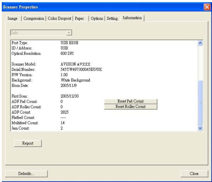
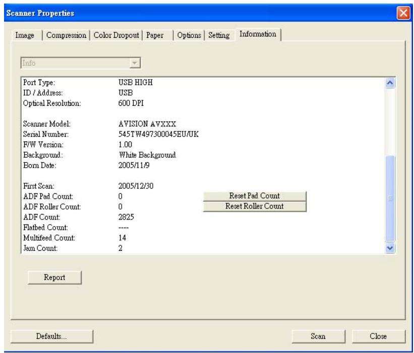
4.8 THE INFORMATION TAB
The Information tab displays the following system and scanner information.
The Information tab dialog box
The "Report" button :
If you encounter any error message while using the scanner, click the Report button. A report.txt file (C:\AVxxx) will be generated. Please send this file to the nearest service center for trouble shooting.
The "Reset Pad Count" button:
After scanning approximately 50,000 pages (the number varies based on type of scanner) through the Auto Document Feeder (ADF), the ADF pad may be worn out and you may experience problems with document feeding. In this case, it is highly recommended to replace the ADF pad with a new one. (Please refer to the manual for proper replacing procedure.) For ordering the ADF pad, please consult your nearest dealer. After replacing the ADF pad, click the "Reset Pad Count" button to reset the pad count.
The "Reset Roller Count" button:
After scanning approximately 200,000 pages through the ADF, the ADF roller may be worn out and you may experience problems with document feeding. In this case, it is highly recommended to replace the ADF roller with a new one. After replacing the ADF roller, click the “Reset Roller Count” button to reset the roller count.
Note :
The lifetime and the replacing procedure vary based on type of scanner. Please consult your nearest dealer for more details.
5. ISIS INTERFACE
OPERATION
The ISIS driver operation method is similar to the TWAIN's.
Every function on the ISIS interface screen is briefly
described as below:
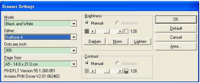
Mode: Select one of scan modes, including B&W, gray,
color options.
Dither: 5 halftone levels available, can be disabled.
Dots per inch: Select your desired resolution.
Paper Size: Select your desired paper size.
Brightness: Adjust your scan image brightness or
darkness.
Contrast: Adjust the range between the darkest and the
lightest shades in the image.
Default: Click to reset all settings.
Area: Select your desired scan area or position.
6. MAINTAINENCE
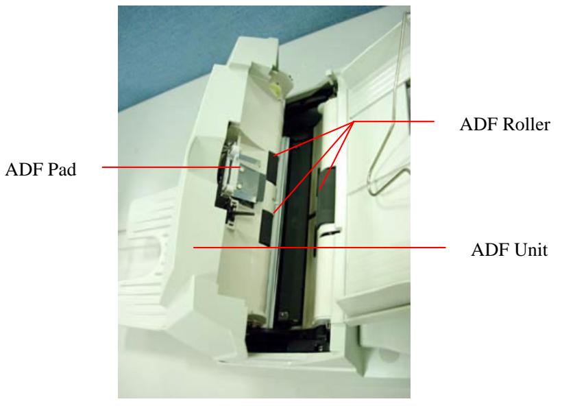
6.1 CLEANING THE ADF
The scanner is designed to be maintenance free. However, it still needs to be cleaned occasionally to ensure optimum image quality and performance.
From time to time the pad assembly and feeding rollers may become contaminated with ink, toner particles or paper dust. In this case the scanner may not feed documents smoothly or several documents may feed at once. If this occurs please follow the cleaning procedures to return your scanner to its original state.
The cleaning procedures
i). Moisten a cotton swab with isopropyl alcohol (95%). (Cleaner kits are available from PictureVision.)
ii). Carefully open the ADF to the left. Wipe the feeding rollers by moving the swab from side to side. Rotate the rollers forward with your finger and repeat the above cleaning procedures until the rollers are clean. Be careful not to snag or damage the pick springs.
iii). Wipe the pad in the direction from top to bottom. Be careful not to hook the pick springs.
iv). Close the ADF unit. Your scanner is now ready for use.
6.2 CLEANING THE GLASS
The procedures:
i). Soak a cotton swab with some isoprophy alcohol (95%).
ii). Open the ADF unit and document cover as shown in Figure 6-2. Wipe the glass of flatbed area and ADF area by moving the swab from side to side.
iii). Close the ADF unit and document cover. Your scanner is now ready for use.
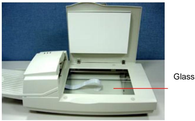
Figure 6-2 The Cleaning Area
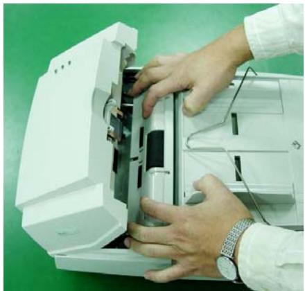
6.3 REPLACING THE ADF SNAP-IN PAD MODULE
After scanning approximately 20,000 pages through the ADF, the separation pad may be worn out and you may experience problems with document feeding. In this case, it is highly recommended to replace the pad module with a new one. For ordering the pad module, please consult your nearest dealer and follow the procedure below to replace it.
Disassembling Procedure
- Open the ADF cover.
- Remove the ADF snap-in pad module by pulling out the upper part of the pad clamp as shown in Figure 6-3.
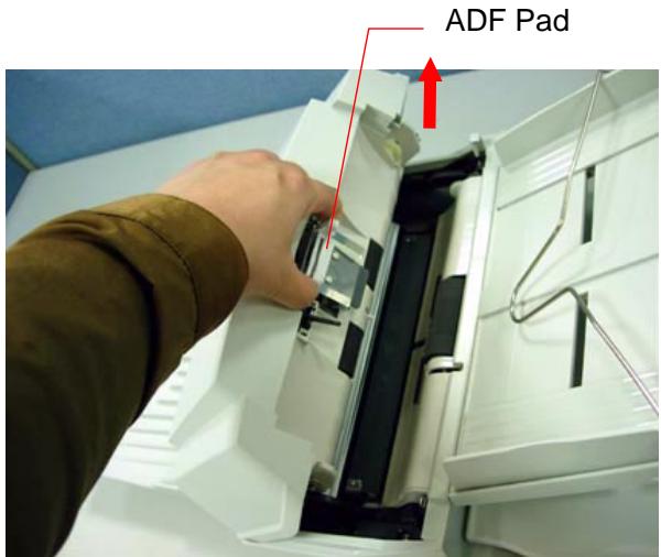
Figure 6-3 Remove the ADF Pad
Assembling Procedure
- Take out the ADF pad module from the box.
- Hold the upper part of the pad clamp and place it gently to the pad holder as shown in Figure 6-4.

Figure 6-4 Installing the ADF Pad
6.4 REPLACING THE ADF PAPER FEED ROLLER
- Open the ADF cover.
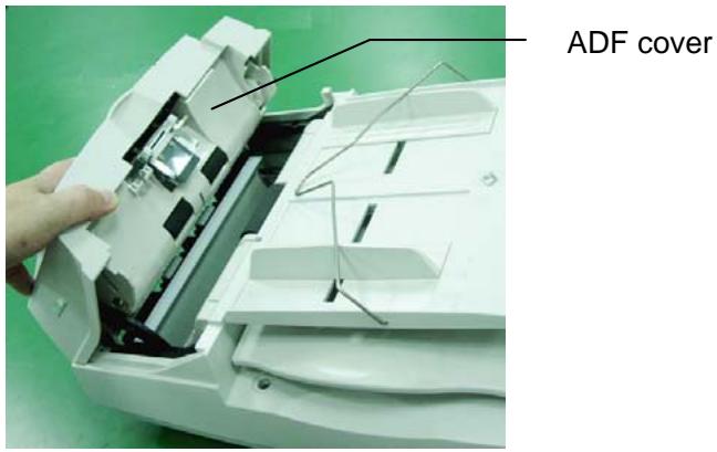
- Lift the tabs.
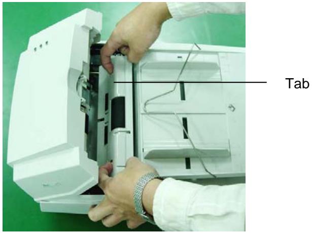
- Remove the paper feed roller cover.
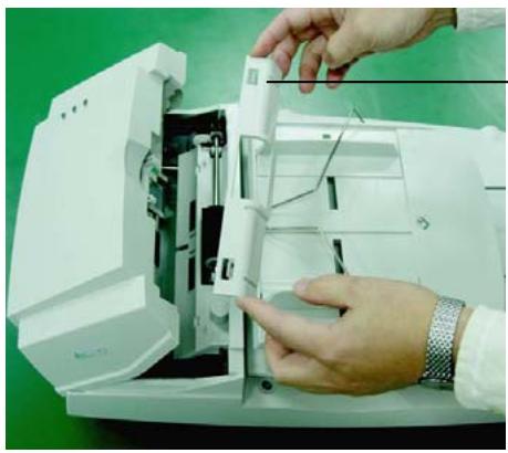
ADF roller cover
- Remove the paper feed roller.
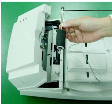
ADF paper feed roller
- Insert the new paper feed roller by aligning the tabs into the slots and pressing the roller into place.
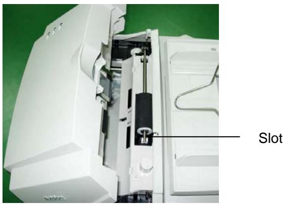
- Reinsert the paper feed roller cover and snap it into place.
- Close the ADF cover.
7. TROUBLE SHOOTING
The scanner will automatically perform a simple self-test each time it is turned on. This will help spot major system errors in the scanner itself.
When the test is initiated, the READY LED is flashing. When the test is completed, if no error occurs, the READY LED is steadily on.
If you have problems with the operation of your scanner, please check the following troubleshooting hints.
7.1 QUESTION AND ANSWER
Question: The LED indicates that the scanner is ready, but the scanner does not respond to the scan command from the host computer.
Answer: a) Please check if the signal cable is firmly seated, and invoke the scan command again. If there is still no response, please reset the scanner by turning it off and then on again, and reboot your host computer as well.
b) Check if the driver is correctly installed.
Question: Paper becomes jammed during scanning.
Answer: a) Open the ADF unit.
b) Pull out the jammed paper carefully.
c) Close the ADF unit.
Question: More than one sheet of paper were fed into the scanner.
Answer: a) Open ADF unit.
b) Remove the multi-fed sheets of paper.
c) Close the ADF unit.
d) Flatten the corners and edges; loosen the paper before reloading it in the paper guide.
e) Check the feeding roller condition and do the cleaning if necessary.
Question: Paper becomes skewed in the scanner.
Answer: a) Check the feeding roller condition; do the cleaning if necessary.
b) Use the paper guide when feeding the paper.
Question: When I power on the scanner, it makes noises and will not stand ready.
Answer: There are two possibilities:
a) You forgot to remove the shipping switch from the scanner. Please remove the shipping retainer first.
b) You did not place the scanner on a flat desktop surface. This may cause the scanner to function improperly.
Question: When I power on the scanner, the lamp does not light.
Answer: The possibilities are as follows:
a) The lamp is out of order. In that case, contact your authorized local dealer to change the lamp. The life time of the lamp is about 5000 hours.
b) Check whether the power LED on ADF cover steadily lights or not.
If it flashes, the power adapter malfunctions or the main board is short-circuited.
Contact your authorized local dealer to replace the power adapter or main board.
Question: Getting image from the scanner is not a problem, but when scanning, the scanner or system will often crash.
Answer: Please check
a) If the SCSI cable or the USB cable is firmly seated;
b) Only two SCSI terminators can be connected to your SCSI daisy chain. One is at the end of the SCSI device, and another is already in your host adapter.
Question: The scanned image always comes out to be too dark.
Answer: a) Use your application to modify the Gamma setting to 2.2 and 1.8 for your printer and monitor respectively.
b) Use Brightness setting from the TWAIN user interface to get a brighter image.
Question: The scanner works well otherwise, but for the line art, the lines scanned seem much thicker than those of the original.
Answer: Use the Brightness or Threshold setting to adjust the line art image.
7.2 PAPER JAM IN THE ADF
In the event of paper jam, please follow the procedures below.
i). Open the ADF cover as shown in Figure 7-1.
ii). Pull the paper out of the ADF unit carefully.
ADF Unit
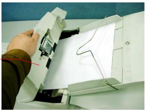
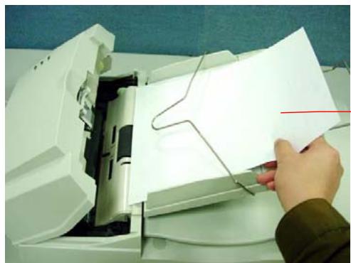
Figure 7-1 ADF Paper Jam - Removing the Paper
Document
8. TECHNICAL SERVICE
Technical support for Avision scanner is provided at Avision Technical Assistance Center (ATAC). Before contact with ATAC, please prepare the following information.
- Scanner serial & revision number (located on the bottom of the scanner)
- Hardware configuration (e.g., your host CPU type, RAM size, free disk space, display card, interface card, etc.)
- The name and version of your software application
The version of your scanner driver.
Please call us at:
US and Canada Area: Avision Labs., Inc.
Address: 6815 Mowry Ave. Newark CA 94560, USA
Telephone: +1 (510) 739-2369
Fax number: +1 (510) 739-6060
Web Site: http://www.avision.com
E-mail: support@avision-labs.com
Other Area: Avision Inc.
Address: No.20, Creation Road I, Hsinchu Science Park, Taiwan, R.O.C.
Telephone: +886 (3) 578-2388
Fax number: +886 (3) 577-7017
Web Site: http://www.avision.com
Email: service@avision.com.tw
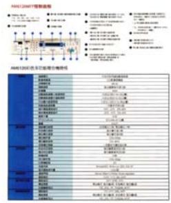
9. SPECIFICATIONS
Model Number
300500001 (Simplex Scanner)
300500002 (Duplex Scanner)
Scanning Mode B&W
Gray
Color
Optical 600x600dpi
Resolution
Light Source Cold Cathode fluorescent lamp
ADF Capacity 50 sheets
Scan Area Flatbed: up to European A4
(8.5^ × 11.69^ )
ADF: 3.7'' × 5.5'' (Min)
ADF: 8.5'' × 14'' (Max)
Interface SCSI-2/USB 2.0
Power 24Vdc/2A
Requirement
Power < 48 watts
Consumption
Operation 5^ C to 35^ C
Temperature
Storage -40°C to 60°C
Temperature
Dimension 567× 350× 199mm
Weight 7.2 kg (15.87 lbs)
INDEX
A
Additional Length Detection, 4-25
ADF cover, 7-5
ADF Scanning, 2-9
B
B&W, 4-6
Background Level, 4-18
Background Setting, 4-33
balance wire, 2-9
Binarization
Dynamic Threshold, Fixed
Processing, 4-7
Blank Page Removal, 4-30
Brightness, 4-10
C
Cleaning the Glass, 6-3
Color, 4-6
Color Dropout
Remove Red, Remove
Green, Remove Blue, 4-
17
Connecting the Cable, 2-10
Contrast, 4-10
Cropping
Automatic, Fixed to
Transport, EOP
Detection, 4-21
D
default settings, 4-3
Deskew, 4-24
document cover, 2-6
Document Loading, 2-8
E
Edge Fill, 4-31
Energy Saving, 4-34
F
Filter Threshold, 4-18
Flip Side Rotation, 4-29
G
G4, 4-15
Gray, 4-6
I
Invert, 4-12
J
JPEG, 4-15
M
Mirror, 4-32
Multi-Feed Detection, 4-25
0
output paper tray, 2-7
output paper tray extension, 2-7
OverScan, 4-24
P
paper jam, 2-9, 7-5
POWERLED,2-10
protrusions, 2-7
R
reference mark, 2-8
refit the shipping bracket, 2-3
Reset Pad Count, 4-37
Reset Roller Count, 4-37
Resolution, 4-11
Rotate Image, 4-30
S
Scan Area, 4-24
Scanner packing, 1-2
SCSI chain, 2-4
SCSI ID selector, 2-4
SCSI Termination, 2-10