
AVN8826 - Car stereo ECLIPSE - Free user manual and instructions
Find the device manual for free AVN8826 ECLIPSE in PDF.

User questions about AVN8826 ECLIPSE
0 question about this device. Answer the ones you know or ask your own.
Ask a new question about this device
Download the instructions for your Car stereo in PDF format for free! Find your manual AVN8826 - ECLIPSE and take your electronic device back in hand. On this page are published all the documents necessary for the use of your device. AVN8826 by ECLIPSE.
USER MANUAL AVN8826 ECLIPSE
HDD Navigation System with 7 "Wide TFT Display and DVD/MS Multi-Source Receiver
MODEL AVN8826
INSTALLATION MANUAL
Be sure to read this installation manual thoroughly before carrying out installation and making connections. If installation methods or non-standard parts that are not specified in this installation manual are used, accidents or injury may result.
Professional installation is recommended, contact the place of purchase to schedule an appointment. After reading the owner's manual and the installation manual thoroughly, keep them in a safe place for later reference.
To dealers:
Give this installation manual to the customer after installation and connections have been completed.

contents
| Before installation | Components | 2 |
| For your safety in using the AVN8826 | 3 | |
| Connections | Names and functions of terminals | 4 |
| Connecting the vehicle speed pulse, parking brake, and reverse cables (wires) | 6 | |
| System connection example | 8 | |
| Installation | Installing the GPS antenna | 9 |
| Installing the main unit | 11 |
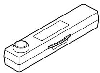
Main unit components
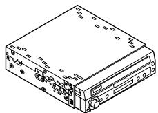
① Main unit
X1
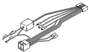
② Interconnecting cable
(Power and speaker connector) (16P) x 1
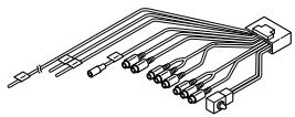
③ Interconnecting cable
(Speed pulse, parking, reverse, video, etc) (20P) x 1
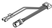
④ Interconnecting cable
(E-lan etc) (16P) x 1
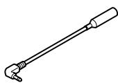
(5) Antenna cable
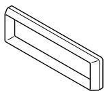
(6) Bezel
x1
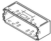
⑦ Mounting sleeve
X1

⑧ Side bracket
X2
Case
(For detachable panel) x 1

Flat head screw
Splicing connector
x3
(M4x6) x 4

② Thin flat screw
(M4x5) x 4

13 Pan
screw with washer
(Blue:M4x3) x 4
GPS antenna components
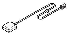
GPS antenna
X1

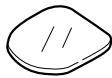
(5) Waterproof cushion
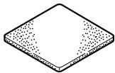
16 Earth plate
X1
X1
17 Body protective sheet
X1
Wiring components

18 Clamp
(for GPS antenna) x 3
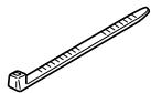
19 Cable tie
X4
② Harness affixing tape
x3

Tip
When installing the main unit, some vehicle models may require the use of items that need to be obtained separately such as a power supply adaptor cable, radio antenna adaptor cable or mounting bracket.
Warnings and caution signs, illustrated below, are posted throughout this manual as well as on the AVN8826. They show safe and correct ways to handle the product so as to prevent personal injury to you and others and avoid damage to property.
Before reading through the manual, take time to read through and learn the important information listed in this section.

Warning

Caution
This sign indicates a situation in which incorrect handling through disregard of a sign might result in death or serious personal injury.
This sign indicates a situation in which incorrect handling through disregard of a sign might result in personal injury or may result solely in damage to property.

Tip
This section contains information that can help to prevent problems and damage to the unit, and also contain other useful information.
Warning
- Do not install this product in locations where it may obstruct the driver's view, or where it may endanger passengers in the vehicle. Otherwise, an accident or injury may result.
- Do not install this product in locations where it may interfere with the operation of the steering wheel, shift lever, brake pedal, etc. Otherwise, an accident or injury may result.
- To prevent damage to the vehicle, confirm the locations of hoses, electrical wiring, and the fuel tank prior to drilling holes to install this product. Also, take precautions so that the product does not interfere, nor come in contact with them. Otherwise, a fire may result.
- When installing this product, never use the existing nuts or bolts that secure parts of the fuel tank, or the steering, or braking systems. Otherwise, improper steering, or braking or a fire may result.
- To prevent a short circuit from occurring, disconnect the battery's negative terminal before installing this product. Otherwise, an electric shock or injury may result.
- When using an existing nut and/or bolt from the vehicle to earth this product, do not use any that secure parts of the steering or braking systems. Otherwise, an accident may result.
- Bundle cables and harnesses with electrical tape or wire ties to prevent them from interfering with moving parts. If they should entangle with the steering wheel, shift lever, or brake pedal, an accident may result.
- Never supply power to another electrical appliance by splicing or tapping into this product's power lead (wire). Otherwise, the current capacity of the wire will be exceeded, resulting in a fire or electric shock.
- Never attempt to disassemble or modify the product. Otherwise, an accident, fire, or electric shock may result.
-
When installing the product into a vehicle with a passenger side air bag, do not secure it to the air bag's cover or in places where it may impede air bag deployment. Otherwise, proper air bag operation may not be ensured in the event of an accident, causing injury or death.
-
When making holes (example: drilling), be sure to wear protective eyewear. Otherwise, an injury such as loss of eyesight may result.
- Exposed wires must be insulated with electrical tape. Otherwise, a short circuit, fire, or electric shock may result.
- Do not modify this system for use other than that specified herein. Also, do not deviate from the installation procedures described herein; Fujitsu ten will not be held liable for damages including, but not limited to serious injury, death, or property damage resulting from installations that enable unintended operation.
- This unit is intended for operation in 12volt DC, negative-grounded vehicles only. Never use it in 24-volt vehicles such as heavy trucks or diesel vehicle with cold-region specifications.
- Do not place the vinyl storage bag over a person's head. It may cause a serious accident or death by suffocation.
- Do not disassemble or rebuild this product. Doing so may cause an accident, fire, or electrical shock.
- When it is necessary to replace the fuse, always use a fuse of the correct rating (number of amperes). Use of fuses with higher amperage ratings may cause a fire.
- Do not operate the product in a malfunctioning condition, for instance, when the audio does not play. Doing so may result in an accident, fire, or electrical shock.
- If an abnormal situation occurs, such as foreign matter entering or liquid splashing on the product, or smoke or a strange odour emitting from the unit, shut off the product immediately and consult the dealer from whom you purchased it. Continued operation may cause an accident, fire, or electrical shock.
Caution
- For best results, this product should be installed by a professional installer.
Contact the dealer whom you purchased the product for an appointment. - When installing this product, be sure to use the supplied mounting hardware. If parts other than those supplied are used, the unit may be damaged internally, or may not be held in place securely and become dislodged.
- Avoid installing this product in places where it may get wet, such as near windows, or in places that are moist or dusty. Presence of liquid, moisture, or dust inside this product can cause short circuiting resulting in smoke or fire.
-
If this product is not connected properly, a short circuit, fire, or accident may occur.
-
When routing cables, use precautions to prevent contact of sharp metal parts such as brackets or screw tips. Otherwise, a short circuit, electric shock, fire, or accident may result.
- Play the audio at a moderate volume level that permits you to hear sounds from outside the vehicle. Driving without being able to hear outside sounds may result in an accident.
- This product must be operated only as on-board equipment, or it may cause electrical shock or injury.
- Do not play distorted sounds for long periods of time; the speakers may overheat and cause a fire.
Warning
- Never cut the insulation on the power cable or use it to power any other equipment. If the rated current capacity of the power cable is exceeded, fire and electric shocks may result.
- The cables should be secured with tape or a similar securing method to prevent any obstructions while driving. If they get wound or entangled around components such as the steering wheel, shifting lever, or brake pedal, accidents may result.
- If removing the end of the cord to connect to another cord, be sure to wrap PVC tape or a similar wire insulating method around the connection to insulate it. If the connection is not insulated, fire or accidents may result.
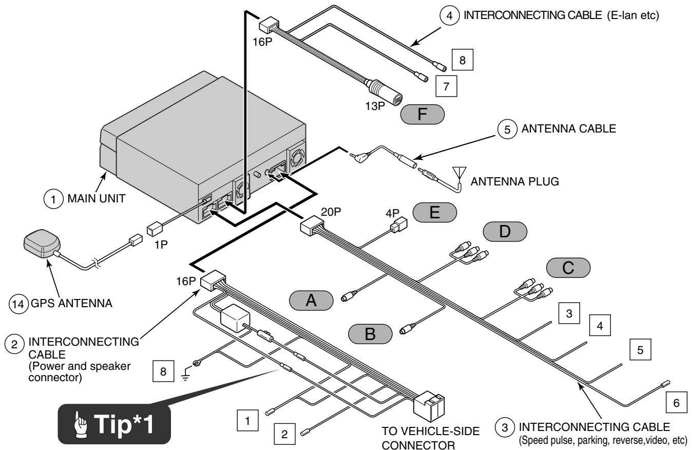

Tip*1
- The positions of the B+ and ACC pins on the connector may vary depending on the vehicle. In such cases, replace the end of the connector. Ask your dealer for details on connector pin positions.
Caution
- Installation is not possible for vehicles without ACC.
Tip
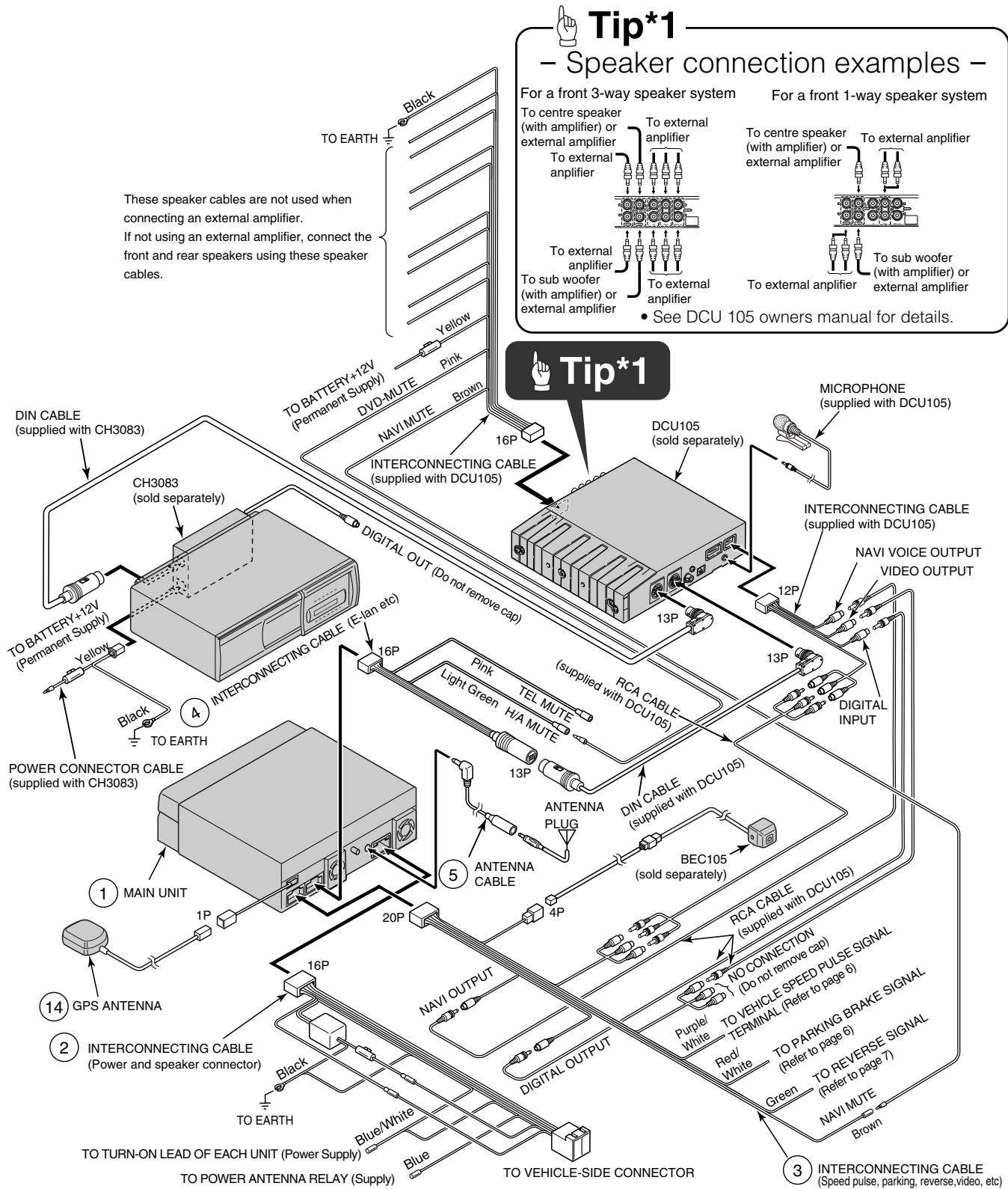
- Refer to page 5 for details on the wire colours and connection points for interconnecting cables ② , and ③ and ④ .
Antenna power supply (Blue)
Connect to the automatic-antenna control terminal of the vehicle.
2 Control power supply (Blue/White)
Connect the control terminal for the external amplifier, etc.
Vehicle speed pulse signal wire (Purple/White)
Connect to the vehicle speed pulse signal terminal.
4 Parking brake signal wire (Red/White)
Connect to the parking brake signal terminal.
5 Reverse signal Wire (Green)
Connect the reverse signal output of the vehicle to this terminal.
6 Navi mute Wire (Brown)
Connect to the NAVI-MUTE terminal of a DCU105 or similar device (sold separately).
7 Cellular phone mute Wire (Pink)
Connect to the earth output terminal on a mobile phone.
H/A mute Wire (Light Green)
Connect to the DVD-MUTE terminal of a DCU105 or similar device (sold separately).
Earth (Black)
Connect where good body earthing is available.
A NAVI-VOICE output terminal
Connect to the NAVI-VOICE input terminal of an external device such as a DCU105 (sold separately).
B Digital output terminal
Connect to the DIGITAL input terminal of an external device such as a DCU105 (sold separately).
C VTR input terminals
Connect the output cable of external video equipment such as a VTR.
Yellow : Video signal White : Audio (left) signal Red : Audio (right) signal
D VTR output terminals
Connect to the monitor with video input.
Yellow : Video signal White : Audio (left) signal Red : Audio (right) signal
E Back-eye camera external input terminal (4P)
Used with the Eclipse back-eye camera (sold separately).
F E-LAN terminal (13P)
Connect to the E-LAN terminal of the CD changer, etc.
- Vehicle connections -
Tip
- You will need to purchase the necessary component adapter cable for the vehicle so that the power supplies can be utilised. (Contact the dealer for further details.)
- Be sure to wrap the connection cables with plastic tape to insulate them.
Connecting the vehicle speed pulse, parking brake, and reverse cables (wires)
Notes on installation
Warning
- Check the vehicle speed pulse signal, parking brake signal, and reverse signal carefully before making the connections. If the cables are incorrectly connected, accidents or problems with correct operation may result.
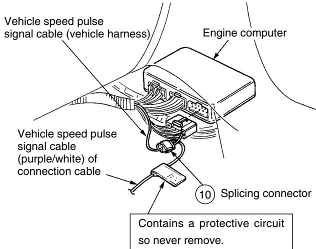
- The label on the vehicle speed pulse signal cable contains a protection circuit, so do not cut the cable or remove the protective circuit, otherwise problems with operation may result.
- Bind the cables together with tape so that they do not cause an obstruction while driving. If they become wound or entangeled around parts such as the steering wheel, shifting lever, or brake pedal, accidents may result.
Tip
The locations where the vehicle speed pulse signal cable, parking brake signal cable, and reverse cable may vary depending on the vehicle model and grade. Ask the car dealer or your nearest Eclipse dealer for details.
- Connecting point for the vehicle speed pulse signal (example) -
Tip
Always be sure to connect the vehicle speed pulse, otherwise the measurement precision will be greatly reduced.
1 Use a splicing connector to connect the vehicle speed pulse signal cable (purple/white) coming from the main unit to the vehicle speed pulse signal cable of the vehicle.
2 Route the vehicle speed pulse signal cable to the main unit.
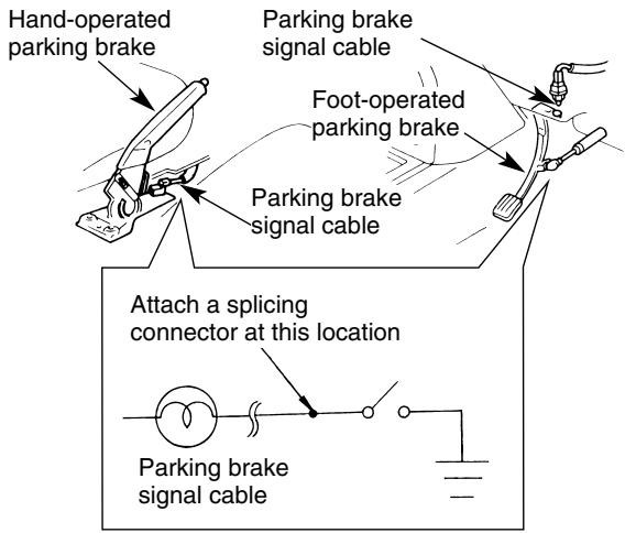
- Connecting the point for parking brake (example) -
1 Use a splicing connector to connect the parking brake signal cable (red/white) coming from the main unit to the parking brake signal cable of the vehicle.
2 Route the parking brake signal cable to the main unit.

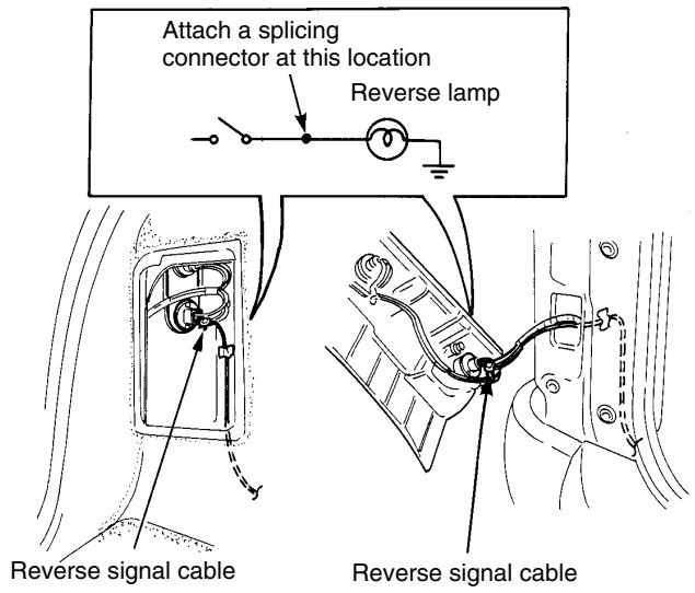
Tip
- Be sure to connect the reverse signal cable. If it is not connected, the vehicle position may be incorrect when the vehicle is reversed.
- Use a circuit tester to confirm that a sensing voltage of 6V or higher is generated when the vehicle is reversed.
1 Use a splicing connector to connect the reverse signal cable (green) coming from the main unit to the reverse signal cable of the vehicle.
2 Route the reverse signal cable to the main unit.
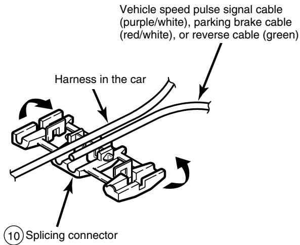
- Using the splicing connector -
1 Insert the connection cable [vehicle speed pulse signal cable (purple/white), parking brake signal cable (red/white), or reverse signal cable (green)] from the main unit and the vehicle cable into the splicing connector.
Push in the terminal (the metal part) of the splicing connector using a pair of pliers.
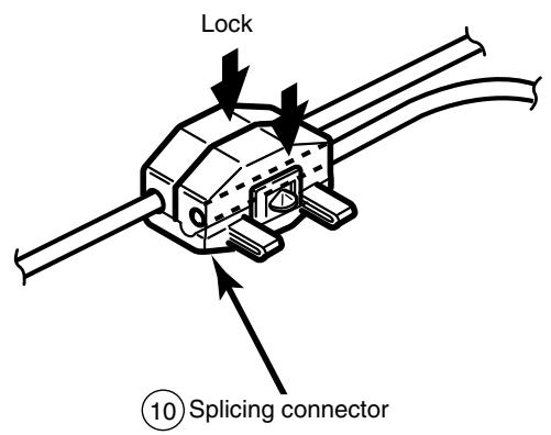
3 Press down the cover of the splicing connector and squeeze it until it locks.
Warning
- Never cut the insulation on the power cable or use it to power any other equipment. If the rated current capacity of the power cable is exceeded, fire and electric shocks may result.
- The cables should be secured with tape or a similar securing method to prevent any obstructions while driving. If they get wound or entangled around components such as the steering wheel, shifting lever, or brake pedal, accidents may result.
- If removing the end of the cord to connect to another cord, be sure to wrap PVC tape or a similar wire insulating method around the connection to insulate it. If the connection is not insulated, fire or accidents may result.
Tip
- Install and connect all of the peripheral units before connecting them to the main unit.
- Do not remove any of the protective caps (RCA, etc.) unless in use.
- Be sure to wrap the connection cables with tape (PVC tape) to insulate them.
Notes on installation
Warning
- The cables should be bound together with tape or a similar securing method (example: wire ties) so that they do not interfere with driving. If it becomes wound or entangled around parts such as the steering wheel, shifting lever, or brake pedal, accidents may result.
- Do not install the GPS antenna where it will obstruct the driver's vision or where it will be an obstacle while driving, otherwise traffic accidents may result.

Tip
- If the vehicle glass is a special type of glass such as heat-reflective glass or bullet-proof glass, be sure to install the GPS antenna outside of the vehicle. If the GPS antenna is installed inside of the vehicle, the reception sensitivity will severely drop and will affect the accuracy of the position measurement.
- If installing the GPS antenna inside the vehicle, be sure it is mounted to the earth plate.
- If installing the GPS antenna inside the vehicle, the location and the slope of the vehicle's windscreen will determine the accuracy of the GPS antenna to receive the GPS signal. If the GPS antenna location inside the vehicle is hindering the accuracy of the GPS antenna, then you may want to install the antenna outside of the vehicle.
- The materials used in front and rear vehicle windows can cause GPS reception sensitivity to drop significantly. If this happens, install the GPS antenna on the outside of the vehicle.
- If the attachment surface is a non-plastic surface such as genuine leather, wood panel, or cloth, attaching the antenna may damage the surface finish. Do not attach the earth plate to such surfaces.
- Wipe the installation surface thoroughly so that it is clear of any dirt, moisture, or grease before installing the antenna.
- Do not apply any coatings to the GPS antenna, otherwise it may cause a drop in the reception sensitivity of the antenna.
-
Route the GPS antenna cable as far away as possible from TV and radio antennas, and cables, otherwise, it may cause interference with video and audio signals.
-
Do not install the antenna in places (such as front pillars and roof panel) that are shielded from the sky.
- The GPS antenna should be installed in a level position where the signals will be as unobstructed as much as possible, such as on the vehicle's roof. Satellite signals cannot be received if the antenna is obscured or obstructed.
- If installing the GPS antenna outside the vehicle, remove the main antenna unit if leaving the vehicle unattended for long periods in order to prevent theft or malicious damage to the antenna.
- Hold the main antenna unit when removing the antenna. Do not pull on the cable, otherwise it may become damaged and result in problems with correct operation.
- If installing the GPS antenna outside the vehicle, remove the main antenna unit when washing the vehicle. (If you wash the vehicle with the main antenna unit still attached, avoid spraying the cable section directly with water so that no water gets inside the vehicle.)
-
The magnet that is attached to the GPS antenna is extremely strong. Be sure to note the following when installing the antenna.
-
Do not put the antenna down on the earth or on dirty or dusty surfaces. If iron filings become attached to the magnet, they may cause damage to the vehicle's body.
- Keep the antenna away from watches and magnetic cards, otherwise they may be damaged and/or rendered unusable.
1 Choose an installation location on the dashboard which is flat and has a clear view of the sky.

- Select a location that is at least 20 in. away from the main unit. If this is not done, the GPS measurement precision will drop.
- Be sure to use the earth plate when installing the GPS antenna. If the earth plate is not used, the reception sensitivity will drop and will affect the accuracy of the position measurement.
2 Install the earth plate to the dashboard.
3 Install the GPS antenna to the earth plate.
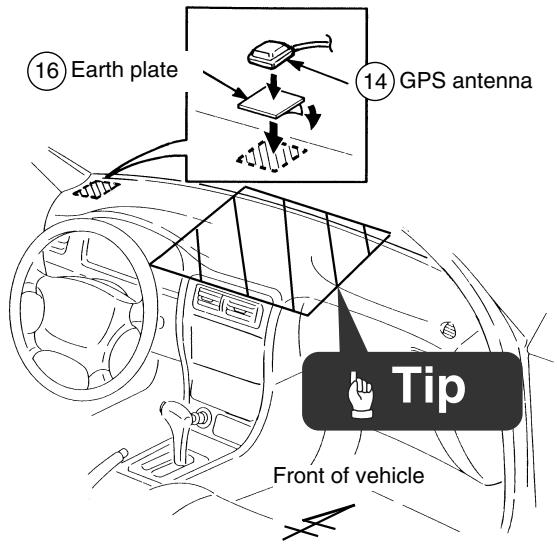

If installing the GPS antenna inside the vehicle, the installation location and the shape of the vehicle's body will determine GPS accuracy. Accuracy is usually lower when the GPS antenna is installed inside the vehicle.
4 Route the GPS antenna cable to the main unit's installation location.

Cut the harness affixing tape into usable lengths with scissors. Do the same for the rest of the installation.
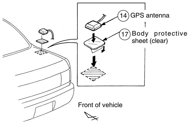
- Installation outside the vehicle (example) -
1 Choose an installation location where the GPS antenna can be attached securely.
2 Remove the backing paper from the body protective sheet and attach the sheet to the vehicle.
3 Install the GPS antenna on top of the body protective sheet.
4 Route the GPS antenna cable inside the vehicle's boot and secure it with clamps.
5 Attach the waterproof cushion so that the GPS antenna cable is flat against the weatherstrip when the boot lid is closed.

To aid in sliding the waterproof cushion in finding the desired mounting location, apply plain or soapy water to the waterproof cushion.
6 Route the GPS antenna cable to the main unit while securing it with harness affixing tape.
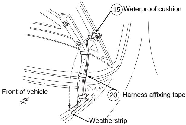

Cut the harness affixing tape into usable lengths with scissors. Do the same for the rest of the installation.
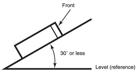
- Installation angle -

To maintain proper function, the unit must be mounted less than 30 degrees. If the angle is in excess of 30 degrees, DVD/CD skipping and improper DVD/CD and Memory Stick ejection may occur.
- Installation preparation

In the event that the main unit requires shipping, reattach the caution label to help prevent potential damage that may be caused by shipping.
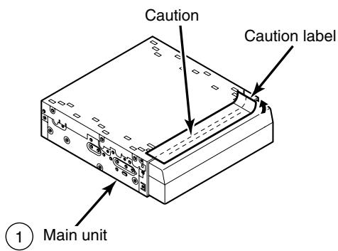
Before the main unit installation, be sure to remove the caution label.
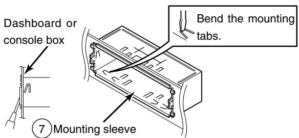
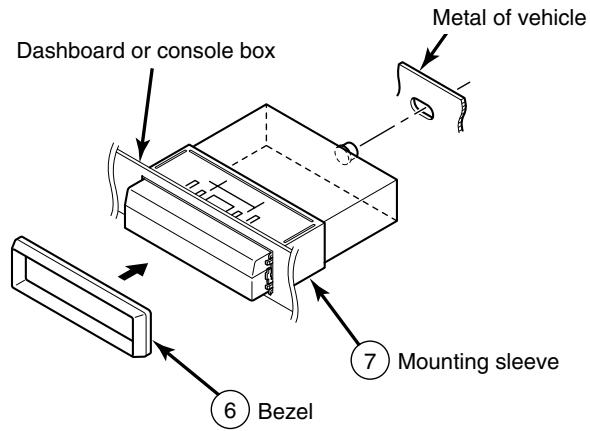
- Main unit installation example (If installing the main unit using the mounting sleeve) -

- Carefully bind any excess length of cord that is connected to the main unit and secure it to an area of empty space in the vehicle so that it does not move around or get caught in the main unit or vehicle-side equipment. If the cords are not handled correctly, operating problems or short-circuits may occur, and this may result in the danger of fire or other accidents.
- Connect all cables before installing the main unit.
1 Insert the mounting sleeve into the opening in the vehicle dashboard or console box.
2 Use a screwdriver or a similar tool to bend the tabs in the mounting sleeve to secure the mounting sleeve.
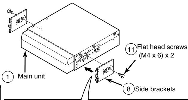
3 Attach the side brackets to the main unit using flathead screws.

Be sure to use the supplied accessory mounting screws (M4 x 6) as the mounting screws. If any other screws are used, they may damage the inside of the unit.
example 1
(1) Main unit
Front of vehicle
8Side brackets
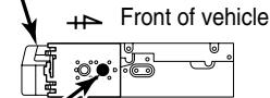
1 Main un
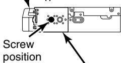
Screw position
8 Side brackets
By adjusting the positions of the brackets, the main unit's installed depth can be adjusted.
4 Insert the main unit into the mounting sleeve until it locks in place.
5 Fasten the rear of the main unit.
6 Install the bezel on the main unit.

- Be careful not to forcefully push on the main unit's display or buttons during installation. This may result in damage to the main unit.
- This installation method is only one example. When installing the main unit to the vehicle, be sure to as the place of purchase for information on what installation method to use.
- Main unit installation example (If installing the main unit using the side brackets of the vehicle) -

- Carefully bind any excess length of cord that is connected to the main unit and secure it to an area of empty space in the vehicle so that it does not move around or get caught in the main unit or vehicle-side equipment. If the cords are not handled correctly, operating problems or short-circuits may occur, and this may result in the danger of fire or other accidents.
- Connect all cables before installing the main unit.
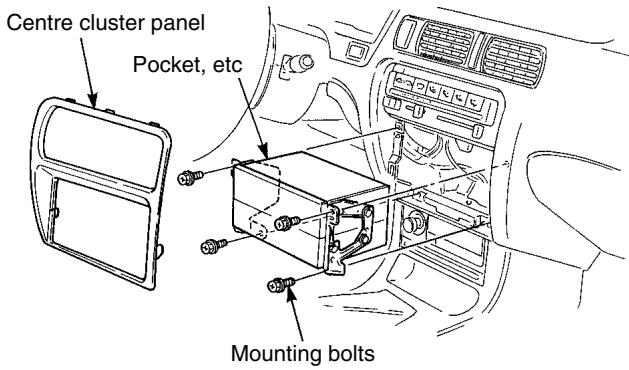
1 Remove the pocket and any other accessories from the centre cluster to make room for the main unit.
2 Remove the mounting brackets for the pocket.
3 Attach the brackets to the main unit.

Be sure to use the supplied accessory mounting screws (M4 x 5) as the mounting screws. If any other screws are used, they may damage the inside of the unit.
4 Install the main unit in the vehicle.

- Be careful not to forcefully push on the main unit's display or buttons during installation. This may result in damage to the main unit.
- This installation method is only one example. When installing the main unit to the vehicle, be sure to as the place of purchase for information on what installation method to use.
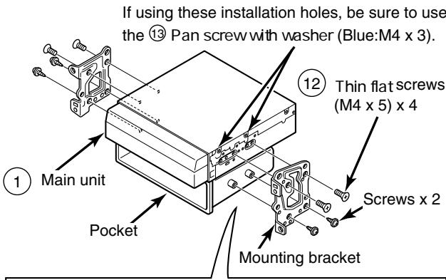

example 1
Main unit
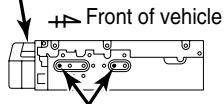
Screw position
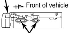
example 2
(1) Main unit
Screw position
By adjusting the positions of the brackets, the main unit's installed depth can be adjusted.