
BR21VPN - Router SMC - Free user manual and instructions
Find the device manual for free BR21VPN SMC in PDF.


User questions about BR21VPN SMC
0 question about this device. Answer the ones you know or ask your own.
Ask a new question about this device
Download the instructions for your Router in PDF format for free! Find your manual BR21VPN - SMC and take your electronic device back in hand. On this page are published all the documents necessary for the use of your device. BR21VPN by SMC.
USER MANUAL BR21VPN SMC
Information furnished by SMC Networks, Inc. (SMC) is believed to be accurate and reliable. However, no responsibility is assumed by SMC for its use, nor for any infringements of patents or other rights of third parties which may result from its use. No license is granted by implication or otherwise under any patent or patent rights of SMC. SMC reserves the right to change specifications at any time without notice.
Copyright © 2008 by
SMC Networks, Inc.
20 Mason
Irvine, CA 92618
All rights reserved. Printed in Taiwan
Trademarks:
SMC is a registered trademark; and EZ Connect is a trademark of SMC Networks, Inc. Other product and company names are trademarks or registered trademarks of their respective holders.
LIMITED WARRANTY
Limited Warranty Statement: SMC Networks, Inc. ("SMC") warrants its products to be free from defects in workmanship and materials, under normal use and service, for the applicable warranty term. All SMC products carry a standard 90-day limited warranty from the date of purchase from SMC or its Authorized Reseller. SMC may, at its own discretion, repair or replace any product not operating as warranted with a similar or functionally equivalent product, during the applicable warranty term. SMC will endeavor to repair or replace any product returned under warranty within 30 days of receipt of the product. The standard limited warranty can be upgraded to a Limited Lifetime* warranty by registering new products within 30 days of purchase from SMC or its Authorized Reseller. Registration can be accomplished via the enclosed product registration card or online via the SMC website. Failure to register will not affect the standard limited warranty. The Limited Lifetime warranty covers a product during the Life of that Product, which is defined as the period of time during which the product is an "Active" SMC product. A product is considered to be "Active" while it is listed on the current SMC price list. As new technologies emerge, older technologies become obsolete and SMC will, at its discretion, replace an older product in its product line with one that incorporates these newer technologies. At that point, the obsolete product is discontinued and is no longer an "Active" SMC product. A list of discontinued products with their respective dates of discontinuance can be found at:
http://www.smc.com/index.cfm?action customer_service_warranty.
All products that are replaced become the property of SMC. Replacement products may be either new or reconditioned. Any replaced or repaired product carries either a 30-day limited warranty or the remainder of the initial warranty, whichever is longer. SMC is not responsible for any custom software or firmware, configuration information, or memory data of Customer contained in, stored on, or integrated with any products returned to SMC pursuant to any warranty. Products returned to SMC should have any customer-installed accessory or add-on components, such as expansion modules, removed prior to returning the product for replacement. SMC is not responsible for these items if they are returned with the product. Customers must contact SMC for a Return Material Authorization number prior to returning any product to SMC. Proof of purchase may be required. Any product returned to SMC without a valid Return Material Authorization (RMA) number clearly
marked on the outside of the package will be returned to customer at customer's expense. For warranty claims within North America, please call our toll-free customer support number at (800) 762-4968. Customers are responsible for all shipping charges from their facility to SMC. SMC is responsible for return shipping charges from SMC to customer.
WARRANTIES EXCLUSIVE: IF AN SMC PRODUCT DOES NOT OPERATE AS WARRANTED ABOVE, CUSTOMER'S SOLE REMEDY SHALL BE REPAIR OR REPLACEMENT OF THE PRODUCT IN QUESTION, AT SMC'S OPTION. THE FOREGOING WARRANTY AND REMEDIES ARE EXCLUSIVE AND ARE IN LIEU OF ALL OTHER WARRANTY OR CONDITIONS, EXPRESS OR IMPLIED, EITHER IN FACT OR BY OPERATION OF LAW, STATUTORY OR OTHERWISE, INCLUDING WARRANTY OR CONDITIONS OF MERCHANTABILITY AND FITNESS FOR A PARTICULAR PURPOSE. SMC NEITHER ASSUMES NOR AUTHORIZES ANY OTHER PERSON TO ASSUME FOR IT ANY OTHER LIABILITY IN CONNECTION WITH THE SALE, INSTALLATION, MAINTENANCE OR USE OF ITS PRODUCTS. SMC SHALL NOT BE LIABLE UNDER THIS WARRANTY IF ITS TESTING AND EXAMINATION DISCLOSE THE ALLEGED DEFECT IN THE PRODUCT DOES NOT EXIST OR WAS CAUSED BY
CUSTOMER'S OR ANY THIRD PERSON'S MISUSE, NEGLECT, IMPROPER INSTALLATION OR TESTING, UNAUTHORIZED ATTEMPTS TO REPAIR, OR ANY OTHER CAUSE BEYOND THE RANGE OF THE INTENDED USE, OR BY ACCIDENT, FIRE, LIGHTNING, OR OTHER HAZARD.
LIMITATION OF LIABILITY: IN NO EVENT, WHETHER BASED IN CONTRACT OR TORT (INCLUDING NEGLIGENCE), SHALL SMC BE LIABLE FOR INCIDENTAL, CONSEQUENTIAL, INDIRECT, SPECIAL, OR PUNITIVE DAMAGES OF ANY KIND, OR FOR LOSS OF REVENUE, LOSS OF BUSINESS, OR OTHER FINANCIAL LOSS ARISING OUT OF OR IN CONNECTION WITH THE SALE, INSTALLATION, MAINTENANCE, USE, PERFORMANCE, FAILURE, OR INTERRUPTION OF ITS PRODUCTS, EVEN IF SMC OR ITS AUTHORIZED RESELLER HAS BEEN ADVISED OF THE POSSIBILITY OF SUCH DAMAGES. SOME STATES DO NOT ALLOW THE EXCLUSION OF IMPLIED WARRANTYES OR THE LIMITATION OF INCIDENTAL OR
CONSEQUENTIAL DAMAGES FOR CONSUMER PRODUCTS, SO THE ABOVE LIMITATIONS AND EXCLUSIONS MAY NOT APPLY TO YOU. THIS WARRANTY GIVES YOU SPECIFIC LEGAL
RIGHTS, WHICH MAY VARY FROM STATE TO STATE. NOTHING IN THIS WARRANTY SHALL BE TAKEN TO AFFECT YOUR STATUTORY RIGHTS.
- SMC will provide warranty service for one year following discontinuance from the active SMC price list. Under the limited lifetime warranty, internal and external power supplies, fans, and cables are covered by a standard one-year warranty from date of purchase.
SMC Networks, Inc.
20 Mason
Irvine, CA 92618
COMPLIANCES
FCC - Class A
This equipment has been tested and found to comply with the limits for a Class A digital device, pursuant to Part 15 of the FCC Rules. These limits are designed to provide reasonable protection against harmful interference in a residential installation. This equipment generates, uses and can radiate radio frequency energy and, if not installed and used in accordance with instructions, may cause harmful interference to radio communications. However, there is no guarantee that the interference will not occur in a particular installation. If this equipment does cause harmful interference to radio or television reception, which can be determined by turning the equipment off and on, the user is encouraged to try to correct the interference by one or more of the following measures:
Reorient the receiving antenna
- Increase the separation between the equipment and receiver
- Connect the equipment into an outlet on a circuit different from that to which the receiver is connected
- Consult the dealer or an experienced radio/TV technician for help
EC Conformance Declaration - Class A
SMC contact for these products in Europe is:
SMC Networks Europe,
Edificio Conata II,
Calle Fructuós Gelabert 6-8, 20, 4a,
08970 - Sant Joan Despi,
Barcelona, Spain.
This information technology equipment complies with the requirements of the Council Directive 89/336/EEC on the Approximation of the laws of the Member States relating to Electromagnetic Compatibility and 73/23/EEC for electrical equipment used within certain
voltage limits and the Amendment Directive 93/68/EEC. For the evaluation of the compliance with these Directives, the following standards were applied:
RFI Emission:
- Limit class A according to EN 55022:1998, IEC 60601-1-2 (EMC,medical)
- Limit class A for harmonic current emission according to EN 61000-3-2/1995
- Limitation of voltage fluctuation and flicker in low-voltage supply system according to EN 61000-3-3/1995
Immunity:
Product family standard according to EN 55024:1998
- Electrostatic Discharge according to EN 61000-4-2:1995 (Contact Discharge: ± 4kV , Air Discharge: ± 8kV )
- Radio-frequency electromagnetic field according to EN 61000-4-3:1996 (80 - 1000 MHz with 1 kHz AM 80% Modulation: 3 V/m)
- Electrical fast transient/burst according to EN 61000-4-4:1995 (AC/DC power supply: ± 1kV , Data/Signal lines: ± 0.5kV )
Surge immunity test according to EN 61000-4-5:1995 (AC/DC Line to Line: ±1 kV, AC/DC Line to Earth: ±2 kV)
- Immunity to conducted disturbances, Induced by radio-frequency fields: EN 61000-4-6:1996 (0.15 - 80 MHz with 1 kHz AM 80% Modulation: 3 V/m)
- Power frequency magnetic field immunity test according to EN 61000-4-8:1993 (1 A/m at frequency 50 Hz)
- Voltage dips, short interruptions and voltage variations immunity test according to EN 61000-4-11:1994 (>95% Reduction @10 ms, 30% Reduction @500 ms, >95% Reduction @5000 ms)
LVD:
EN 60950-1:2001
Please read the following safety information carefully before installing the device:
WARNING: Installation and removal of the unit must be carried out by qualified personnel only.
- This guide is intended for use by network administrators who are responsible for setting up and installing network equipment; consequently it assumes a basic working knowledge of LANs (Local Area Networks).
- The unit must be connected to an earthed (grounded) outlet to comply with international safety standards.
- Do not connect the unit to an A.C. outlet (power supply) without an earth (ground) connection.
- The appliance coupler (the connector to the unit and not the wall plug) must have a configuration for mating with an EN 60320/IEC 320 appliance inlet.
- The socket outlet must be near to the unit and easily accessible. You can only remove power from the unit by disconnecting the power cord from the outlet.
- This unit operates under SELV (Safety Extra Low Voltage) conditions according to IEC 60950. The conditions are only maintained if the equipment to which it is connected also operates under SELV conditions.
Warnings and Cautionary Messages
Warning: This product does not contain any serviceable user parts.
Warning: Installation and removal of the unit must be carried out by qualified personnel only.
Warning: When connecting this device to a power outlet, connect the field ground lead on the tri-pole power plug to a valid earth ground line to prevent electrical hazards.
Caution: Wear an anti-static wrist strap or take other suitable measures to prevent electrostatic discharge when handling this equipment.
Caution: Use only twisted-pair cables with RJ-45 connectors that conform to FCC standards.
Warnings (in German)
Environmental Statement
The manufacturer of this product endeavours to sustain an environmentally-friendly policy throughout the entire production process. This is achieved though the following means:
- Adherence to national legislation and regulations on environmental production standards.
- Conservation of operational resources.
- Waste reduction and safe disposal of all harmful un-recyclable by-products.
Recycling of all reusable waste content. - Design of products to maximize recyclables at the end of the product.s life span.
Continual monitoring of safety standards.
End of Product Life Span
This product is manufactured in such a way as to allow for the recovery and disposal of all included electrical components once the product has reached the end of its life.
Manufacturing Materials
There are no hazardous nor ozone-depleting materials in this product.
Documentation
All printed documentation for this product uses biodegradable paper that originates from sustained and managed forests. The inks used in the printing process are non-toxic.
Purpose
This guide details the hardware features of the product, including Its physical and performance-related characteristics, and how to install the product.
Audience
The guide is intended for use by network administrators who are responsible for installing and setting up network equipment; consequently, it assumes a basic working knowledge of LANs (Local Area Networks).
CHAPTER 1 ADMINISTRATOR. 16
ADMIN 18
LOGOUT 21
SOFTWARE UPDATE 22
CHAPTER 2 CONFIGURE 23
SETTING 28
DATE/TIME 34
MULTIPLE SUBNET 35
ROUTE TABLE 38
DDNS 44
HOST TABLE 46
LANGUAGE 47
CHAPTER 3 INTERFACE. 48
LAN 53
WAN 54
DMZ 62
CHAPTER 4 ADDRESS .64
EXAMPLE 67
CHAPTER 5 SERVICE 74
CUSTOM. 78
GROUP 82
CHAPTER 6 SCHEDULE. 85
EXAMPLE 86
CHAPTER 7 QOS .88
EXAMPLE 92
CHAPTER 8 AUTHENTICATION .94
EXAMPLE. 100
CHAPTER 9 CONTENT BLOCKING 104
URL 108
SCRIPT 111
DOWNSLOAD 113
P2P/IM 115
CHAPTER 10 VIRTUAL SERVER 118
EXAMPLE 122
CHAPTER 11 VPN. 137
EXAMPLE 145
CHAPTER 12 POLICY 169
EXAMPLE 175
CHAPTER 13 ALERT SETTING. 193
INTERNET ALERT 198
CHAPTER 14 ATTACK ALARM. 202
INTERNAL ALARM. 204
EXTERNAL ALARM 205
CHAPTER 15 LOG 207
TRAFFICLOG 209
EVENTLOG. 214
CONNECTIONLOG 217
LOG BACKUP 220
CHAPTER 16 ACCOUNTING REPORT 222
OUTBOUND 225
INBOUND 232
CHAPTER 17 STATISTICS. 238
CHAPTER 18 STATUS. 244
WAN STATISTICS 240
POLICY STATISTICS 242
INTERFACE 245
AUTHENTICATION 247
ARPTABLE. 248
DHCPCLIENTS 249
Chapter 1 Administrator
Administration
"System" is the managing of settings such as the privileges of packets that pass through the SMC BR21VPN and monitoring controls. The System Administrators can manage, monitor, and configure SMC BR21VPN settings. But all configurations are "read-only" for all users other than the System Administrator; those users are not able to change any setting of the SMC BR21VPN.
Define the required fields of Administrator
Administrator Name:
- The username of Administrators and Sub Administrator for the SMC BR21VPN. The admin user name cannot be removed; and the sub-admin user can be removed or configure.

The default Account: admin; Password: smcadmin
Privilege:
- The privileges of Administrators (Admin or Sub Admin). The username of the main Administrator is Administrator with reading / writing privilege. Administrator also can change the system setting, log system status, and to increase or delete sub-administrator. Sub-Admin may be created by the Admin by clicking New Sub Admin. Sub Admin have only read and monitor privilege and cannot change any system setting value.
Configure:
- Click Modify to change the "Sub-Administrator's" password or click Remove to delete a "Sub Administrator."
Admin
Adding a new Sub Administrator
STEP 1. In the Admin WebUI, click the New Sub Admin button to create a new Sub Administrator.
STEP 2. In the Add New Sub Administrator WebUI (Figure 1-1) and enter the following setting:
Sub Admin Name: sub_admin
■ Password: 12345
Confirm Password: 12345
STEP 3 . Click OK to add the user or click Cancel to cancel it.
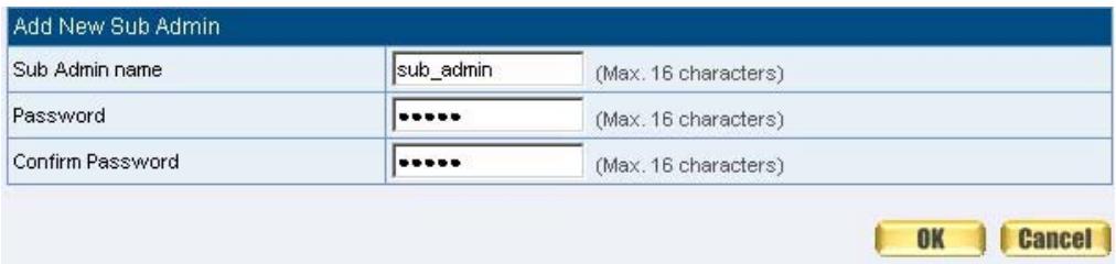
Figure1-1 Add New Sub Admin
Modify the Administrator's Password
STEP 1. In the Admin WebUI, locate the Administrator name you want to edit, and click on Modify in the Configure field.
STEP 2 . The Modify Administrator Password WebUI will appear. Enter the following information:
■ Password: admin
New Password: 52364
Confirm Password: 52364 (Figure1-2)
STEP 3 . Click OK to confirm password change.
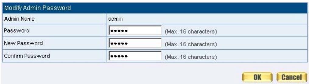
Figure1-2 Modify Admin Password
Add Remote Management IPs
STEP 1. Add the following setting in Permitted IPs of Administration: (Figure1-3)
Name: Enter master
IP Address: Enter 163.173.56.11
Netmask: Enter 255.255.255.255
Service: Select Ping and HTTP
Click OK
Complete add new permitted IPs (Figure1-4)
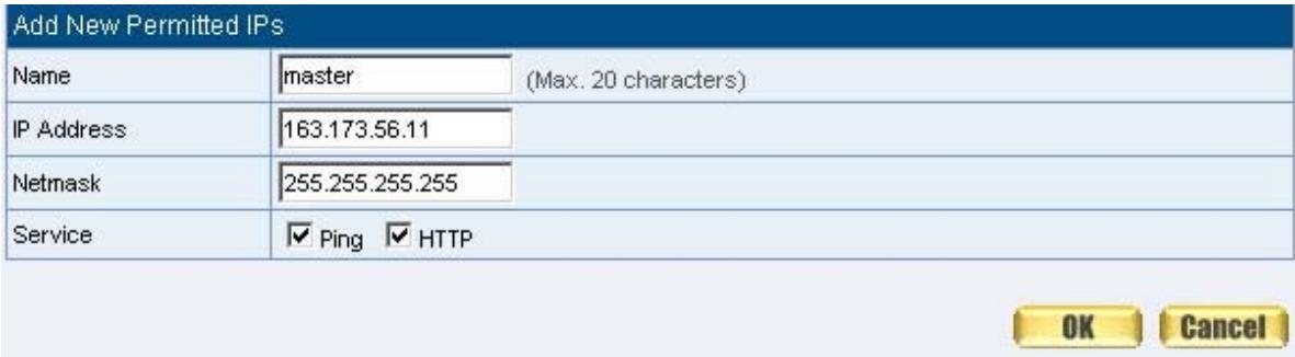
Figure1-3 Setting Permitted IPs WebUI

Figure1-4 Complete Add New Permitted IPs

To make Permitted IPs be effective, it must cancel the Ping and WebUI selection in the WebUI of SMC BR21VPN that Administrator enter. (LAN, WAN, or DMZ Interface) Before canceling the WebUI selection of Interface, must set up the Permitted IPs first, otherwise, it would cause the situation of cannot enter WebUI by appointed Interface.
Logout
STEP 1 . ClickLogout in System to protect the system while Administrator are away. (Figure1-5)
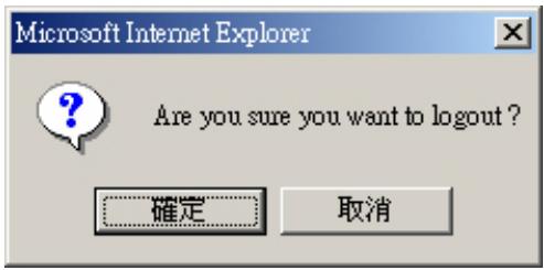
Figure1-5 ConfirmLogout WebUI
STEP 2 . Click OK and the logout message will appear in WebUI. (Figure1-6)
Multi-Homing Gateway Web Server Information
Your current connection has expired, you have now been logged out.
If you want to login, please restart your browser.
Figure1-6Logout WebUI Message
Software Update
STEP 1. Select Software Update in System, and follow the steps below:
To obtain the version number from Version Number and obtain the latest version from Internet. And save the latest version in the hardware of the PC, which manage the SMC BR21VPN
- Click Browse and choose the latest software version file.
- Click OK and the system will update automatically. (Figure1-7)
Software Update
Version Number:
Software Update
v 2.11.02
C:Fineware\SMC\SMC_SN 测算...
(ex:SMC_SMCBR21VPN_021102.img)
OK
Cancel

Figure1-7 Software Update
It takes 3 minutes to update software. The system will reboot after update. During the updating time, please don't turn off the PC or leave the WebUI. It may cause some unexpected mistakes. (Strong suggests updating the software from LAN to avoid unexpected mistakes.)
Chapter 2 Configure
Configure
The Configure is according to the basic setting of the SMC BR21VPN. In this chapter the definition is Setting, Date/Time, Multiple Subnet, Route Table, DHCP, Dynamic DNS, Hosts Table, and Language settings.
Define the required fields of Settings
SMC BR21VPN Configuration:
The Administrator can import or export the system settings. Click OK to import the file into the SMC BR21VPN or click Cancel to cancel importing. You also can revive to default value here.
Email Settings:
- Select Enable E-mail Alert Notification under E-mail Settings. This function will enable the SMC BR21VPN to send e-mail alerts to the System Administrator when the network is being attacked by hackers or when emergency conditions occur. (It can be set from Settings-Hacker Alert in System to detect Hacker Attacks)
Web Management (WAN Interface):
The System Manager can change the port number used by HTTP port anytime. (Remote WebUI management)

After HTTP port has changed, if the administrator want to enter WebUI from WAN, will have to change the port number of browser. (For example: http://61.62.108.172:8080)
MTU Setting:
It provides the Administrator to modify the networking package length anytime. Its default value is 1500 Bytes.
Link Speed / Duplex Mode:
- By this function can set the transmission speed and mode of WAN Port when connecting other device.
Administration Packet Logging:
■ After enable this function; the SMC BR21VPN will record packet which source IP or destination address is SMC BR21VPN. And record in Traffic Log for System Manager to inquire about.
Define the required fields of Time Settings
Synchronize Time/Date:
Synchronizing the SMC BR21VPN with the System Clock. The administrator can configure the SMC BR21VPN's date and time by eitheryncing to an Internet Network Time Server (NTP) or byyncing to your computer's clock.
GMT:
International Standard Time (Greenwich Mean Time)
Define the required fields of Multiple Subnet
Forwarding Mode:
To display the mode that Multiple Subnet use. (NAT mode or Routing Mode)
WAN Interface Address:
The IP address that Multiple Subnet corresponds to WAN.
LAN Interface Address/Subnet Netmask:
The Multiple Subnet range
NAT Mode:
It allows Internal Network to set multiple subnet address and connect with the Internet through different WAN IP Addresses. For example : The lease line of a company applies several real IP Addresses 168.85.88.0/24, and the company is divided into R&D department, service, sales department, procurement department, accounting department, the company can distinguish each department by different subnet for the purpose of managing conveniently. The settings are as the following :
- R&D department subnet: 192.168.1.1/24(LAN) 168.85.88.253(WAN)
- Service department subnet : 192.168.2.1/24(LAN) 168.85.88.252(WAN)
- Sales department subnet : 192.168.3.1/24(LAN) 168.85.88.251(WAN)
- Procurement department subnet 192.168.4.1/24(LAN) 168.85.88.250(WAN)
- Accounting department subnet 192.168.5.1/24(LAN) 168.85.88.249(WAN)
The first department (R&D department) had set while setting interface IP; the other four ones have to be added in Multiple Subnet. After completing the settings, each department uses the different WAN IP Address to connect to the Internet. The settings of each department are as following:
| Service | Sales | Procurement | Accounting | |
| IP Address | 192.168.2.2~254 | 192.168.3.2~254 | 192.168.4.2~254 | 192.168.5.2~254 |
| Subnet Netmask | 255.255.255.0 | 255.255.255.0 | 255.255.255.0 | 255.255.255.0 |
| Gateway | 192.168.2.1 | 192.168.3.1 | 192.168.4.1 | 192.168.5.1 |
Routing Mode:
It is the same as NAT mode approximately but does not have to correspond to the real WAN IP address, which let internal PC to access to Internet by its own IP. (External user also can use the IP to connect with the Internet)
Define the required fields of DHCP
Subnet:
The domain name of LAN
NetMask:
The LAN Netmask
Gateway:
The default Gateway IP address of LAN
Broadcast IP:
The Broadcast IP of LAN
Define the required fields of DDNS
Domain Name:
The domain name that provided by DDNS
WAN IP Address:
The WAN IP Address, which the domain name corresponds to.
Define the required fields of Host Table
Domain Name:
It can be set by System Manager. To let the internal user to access to the information that provided by the host by this domain name
Virtual IP Address:
The virtual IP address respective to Host Table. It must be LAN or DMZ IP address.
Setting
System Settings- Exporting
STEP 1 . In System Setting WebUI, click on Download button next to Export System Settings to Client.
STEP 2 . When the File Download pop-up window appears, choose the destination place where to save the exported file and click on Save. The setting value of SMC BR21VPN will copy to the appointed site instantly. (Figure2-1)
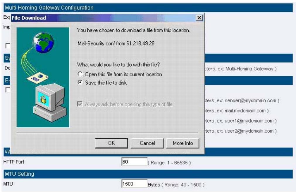
Figure2-1 Select the Destination Place to Save the Exported File
System Settings- Importing
STEP 1. In System Setting WebUI, click on the Browse button next to Import System Settings from Client. When the Choose File pop-up window appears, select the file to which contains the saved SMC BR21VPN Settings, then click OK. (Figure2-2)
STEP 2 . Click OK to import the file into the SMC BR21VPN (Figure2-3)
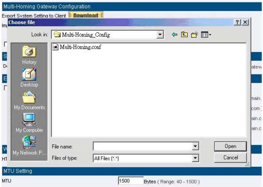
Figure 2-2 Enter the File Name and Destination of the Imported File

Figure 2-3 Upload the Setting File WebUI
Restoring Factory Default Settings
STEP 1 . Select Reset Factory Settings in SMC BR21VPN Configuration WebUI
STEP 2 . Click OK at the bottom-right of the page to restore the factory settings. (Figure2-4)
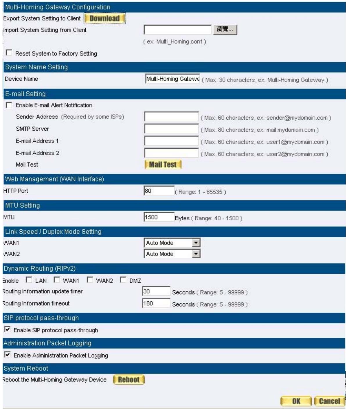
Figure2-4 Reset Factory Settings
Enabling E-mail Alert Notification
STEP 1. Select Enable E-mail Alert Notification under E-Mail Settings.
STEP 2 . Device Name: Enter the Device Name or use the default value.
STEP 3 . Sender Address: Enter the Sender Address. (Required by some ISPs.)
STEP 4 . SMTP Server IP: Enter SMTP server's IP address.
STEP 5 . E-Mail Address 1: Enter the e-mail address of the first user to be notified.
STEP 6 . E-Mail Address 2: Enter the e-mail address of the second user to be notified. (Optional)
STEP 7 . Click OK on the bottom-right of the screen to enable E-mail Alert Notification. (Figure2-5)
E-mail Setting
Enable E-mail Alert Notification
Device Name
Sender Address
SMTP Server
E-mail Address 1
E-mail Address 2
Mail Test
Multi-Homing Gateway
(ex: Multi-Homing Gateway)
sender@mydomain.com
ex: sender@mydomain.com
mail.mydomain.com
(ex: mail.mydomain.com)
user1 @ mydomain.com
(ex: user1@mydomain.com)
user2@mydomain.com
(ex: user2@mydomain.com)
Mail Test

Figure2-5 Enable E-mail Alert Notification
Click on Mail Test to test if E-mail Address 1 and E-mail Address 2 can receive the
Alert Notification correctly.
STEP 1. Reboot SMC BR21VPN: Click Reboot button next to Reboot SMC BR21VPN Appliance.
STEP 2 . A confirmation pop-up page will appear.
STEP 3 . Follow the confirmation pop-up page; click OK to restart SMC BR21VPN. (Figure2-6)
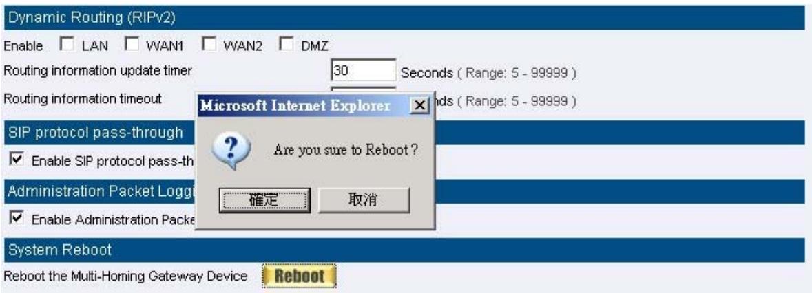
Figure2-6 Reboot SMC BR21VPN
Date / Time
Date/Time Settings
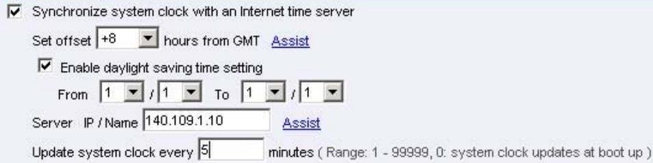
STEP 1 . Select Enable synchronize with an Internet time Server (Figure2-7)
STEP 2 . Click the down arrow to select the offset time from GMT.
STEP 3. Enter the Server IP / Name with which you want to synchronize.
STEP 4 . Set the interval time to synchronize with outside servers.
Synchronize system clock
Synchronize system clock with this client Sync

Figure2-7 System Time Setting
Click on the Sync button and then the SMC BR21VPN's date and time will be synchronized to the Administrator's PC
The value of Set Offset From GMT and Server IP / Name can be looking for from Assist.
Multiple Subnet
Connect to the Internet through Multiple Subnet NAT or Routing Mode by the IP address that set by the LAN user's network card
Preparation
SMC BR21VPN WAN1 (10.10.10.1) connect to the ISP Router (10.10.10.2) and the subnet that provided by ISP is 162.172.50.0/24
To connect to Internet, WAN2 IP (211.22.22.22) connects with ATUR.
Adding Multiple Subnet
Add the following settings in Multiple Subnet of System function:
- Click on New Entry
Alias IP of LAN Interface: Enter 162.172.50.1
Netmask:Enter255.255.255.0
■ WAN1: Enter Interface IP 10.10.10.1, and choose Routing in Forwarding Mode
■ WAN2: Enter Interface IP 211.22.22.22, and choose NAT in Forwarding Mode
Click OK
Complete Adding Multiple Subnet (Figure2-8)
| Add New Multiple Subnet IP | |
| Interface | LAN DMZ |
| Alias IP of Interface | 162.172.50.1 |
| Netmask | 255.255.0.0 |
| WAN Interface IP | Forwarding Mode | ||
| WAN1 | 0.0.0.0 | Assist | C NAT Routing |
| WAN2 | 211.22.22.22 | Assist | C NAT Routing |

Figure 2-8 Add Multiple Subnet WebUI

After setting, there will be two subnet in LAN: 192.168.1.0/24 (default LAN subnet)
and 162.172.50.0/24. So if LAN IP is:
`192.168.1.xx, it must use NAT Mode to access to the Internet. (In Policy it only can setup to access to Internet by WAN2. If by WAN1 Routing mode, then it cannot access to Internet by its virtual IP)
`162.172.50.xx, it uses Routing mode through WAN1 (The Internet Server can see your IP 162.172.50.xx directly). And uses NAT mode through WAN2 (The Internet Server can see your IP as WAN2 IP)(Figure2-9)
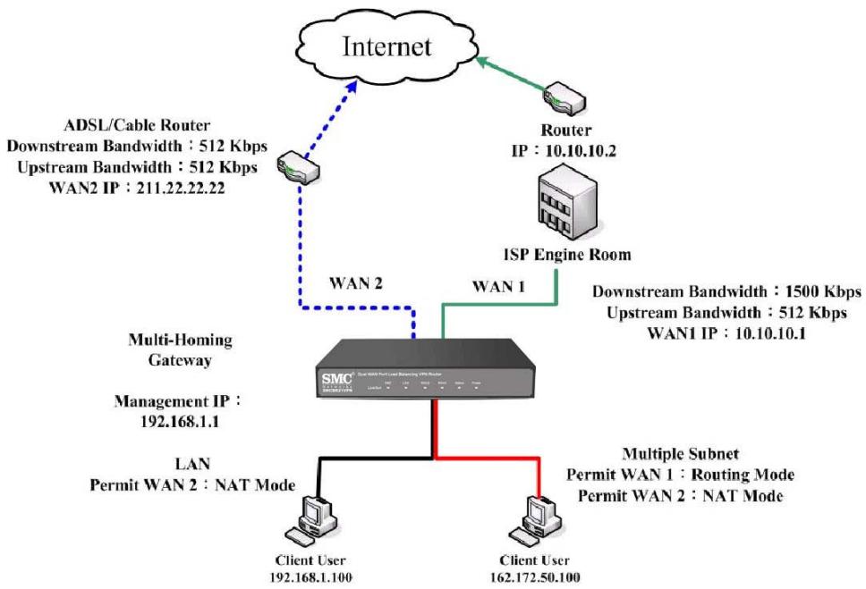
Figure 2-9 Multiple Subnet Network
The SMC BR21VPN's Interface Status:
LAN Port Multiple Subnet : 162.172.50.1
Route Table
To connect two different subnet router with the SMC BR21VPN and makes them to connect to Internet through SMC BR21VPN
Preparation
Company A: WAN1 (61.11.11.11) connects with ATUR to Internet
WAN2 (211.22.22.22) connects with ATUR to Internet
LAN subnet: 192.168.1.1/24
The Router1 which connect with LAN (10.10.10.1, support RIPv2)
its LAN subnet is 192.168.10.1/24
Company B: Router2 (10.10.10.2, support RIPv2), its LAN subnet is
192.168.20.1/24
Company A 's Router1 (10.10.10.1) connect directly with Company B 'sRouter2
(10.10.10.2).
Route Table
STEP 1. Enter the following settings in Route Table in System function:
【Destination IP】: Enter 192.168.10.1
【Netmask】: Enter 255.255.255.0。
【Gateway】: Enter 192.168.1.252
【Interface】: Select LAN
- Click OK (Figure 2-10)
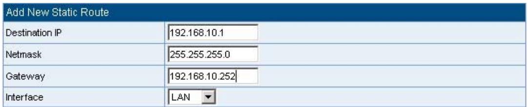

Figure2-10 Add New Static Route1
Cancel
STEP 2. Enter the following settings in Route Table in System function:
【Destination IP】: Enter 192.168.20.1
【Netmask】: Enter 255.255.255.0
【Gateway】: Enter 192.168.1.252
【Interface】: Select LAN
- Click OK (Figure 2-11)
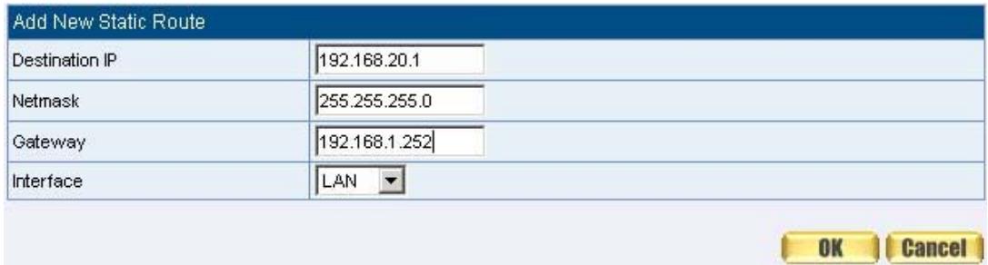
Figure2-11 Add New Static Route2
STEP 3. Enter the following setting in Route Table in System function:
【Destination IP】: Enter 10.10.10.0
【Netmask】: Enter 255.255.255.0
【Gateway】: Enter 192.168.1.252
【Interface】: Select LAN
- Click OK (Figure 2-12)
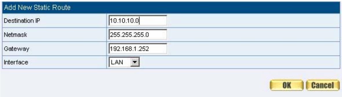
Figure2-12 Add New Static Route3
STEP 4 . Adding successful. At this time the computer of 192.168.10.1/24, 192.168.20.1/24 and 192.168.1.1/24 can connect with each other and connect to Internet by NAT (Figure 2-13)
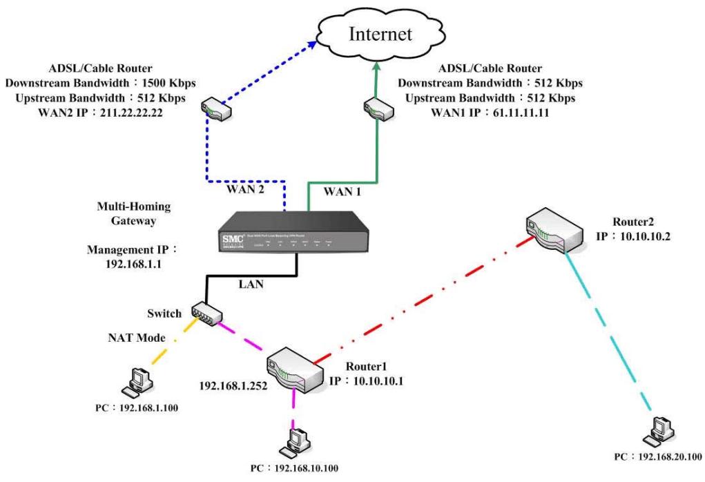
Figure 2-13 Route Table Setting
DHCP
STEP 1. Select DHCP in System and enter the following settings:
- Domain Name : Enter the Domain Name
DNS Server 1: Enter the distributed IP address of DNS Server1.
DNS Server 2: Enter the distributed IP address of DNS Server2.
■ WINS Server 1: Enter the distributed IP address of WINS Server1.
WINS Server 2: Enter the distributed IP address of WINS Server2.
LAN Interface:
Client IP Address Range 1: Enter the starting and the ending IP address dynamically assigning to DHCP clients. The default value is 192.168.1.2 to 192.168.1.254 (it must be in the same subnet)
Client IP Address Range 2: Enter the starting and the ending IP address dynamically assigning to DHCP clients. But it must in the same subnet as Client IP Address Range 1 and the range cannot be repeated.
DMZ Interface: the same as LAN Interface. (DMZ works only if to enable DMZ Interface)
Leased Time: Enter the leased time for Dynamic IP. The default time is 24 hours.
- Click OK and DHCP setting is completed. (Figure2-14)
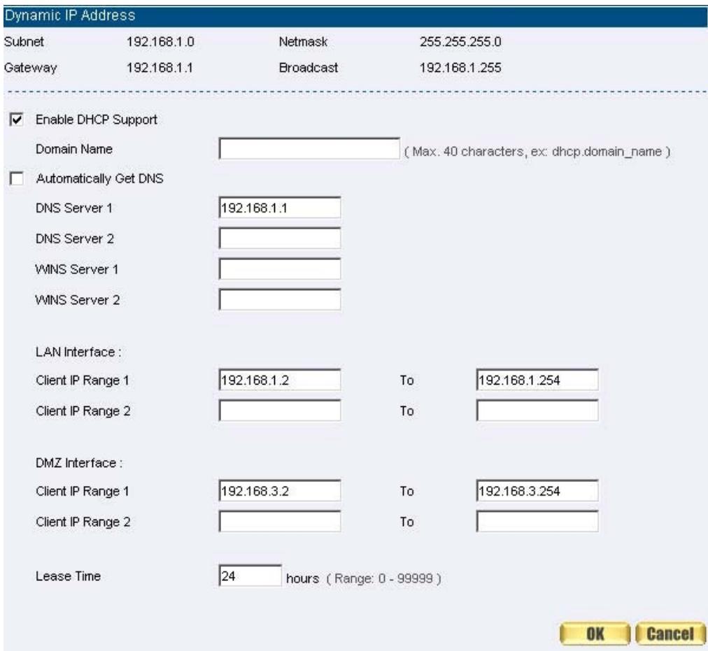
Figure 2-14 DHCP WebUI

When selecting Automatically Get DNS, the DNS Server will lock it as LAN
Interface IP. (Using Occasion: When the system Administrator starts Authentication, the users' first DNS Server must be the same as LAN Interface IP in order to enter Authentication WebUI)
DDNS
Dynamic DNS Settings
STEP 1. Select Dynamic DNS in System function (Figure2-15). Click New Entry button
Service providers : Select service providers.
- Automatically fill in the WAN 1/2 IP : Check to automatically fill in the WAN 1/2 IP.
- User Name : Enter the registered user name.
■ Password : Enter the password
- Domain name: Enter Your host domain name
- Click OK to add Dynamic DNS. (Figure2-16)
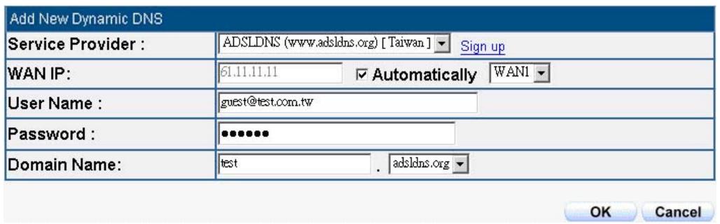
Figure2-15 DDNS WebUI

Figure 2-16 Complete DDNS Setting
| Chart | ||||
| Meaning | Update successfully | Incorrect username or password | Connecting to server | Unknown error |

If System Administrator had not registered a DDNS account, click on Sign up then enter the website of the provider.

If you do not select Automatically fill in the WAN IP and then you can enter a
specific IP in WAN IP. Let DDNS to correspond to that specific IP address.
Host Table
STEP 1 . Select Host Table in Settings function and click on New Entry
Domain Name: The domain name of the server
■ Virtual IP Address: The virtual IP address respective to Host Table
- Click OK to add Host Table. (Figure2-17)

Figure2-17 Add New Host Table

To use Host Table, the user PC's first DNS Server must be the same as the LAN
Port or DMZ Port IP of SMC BR21VPN. That is, the default gateway.
Language
Select the Language version (English Version/ Traditional Chinese Version or Simplified Chinese Version) and click OK. (Figure2-18)
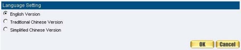
Figure2-18 Language Setting WebUI
Chapter 3 Interface
Interface
In this section, the Administrator can set up the IP addresses for the office network. The Administrator may configure the IP addresses of the LAN network, the WAN 1/2 network, and the DMZ network. The Netmask and gateway IP addresses are also configured in this section.
Define the required fields of Interface
LAN:
Using the LAN Interface, the Administrator can set up the LAN network of SMC BR21VPN.
Ping:
Select this function to allow the LAN users to ping the Interface IP Address.
HTTP:
- Select to enable the user to enter the WebUI of SMC BR21VPN from Interface IP.
WAN:
The System Administrator can set up the WAN network of SMC BR21VPN.
Balance Mode:
Auto: The SMC BR21VPN will adjust the WAN 1/2 utility rate automatically according to the downstream/upstream of WAN. (For users who are using various download bandwidth)
Round-Robin: The SMC BR21VPN distributes the WAN 1/2 download bandwidth 1:1, in other words, it selects the agent by order. (For users who are using same download bandwidths)
■ By Traffic: The SMC BR21VPN distributes the WAN 1/2 download bandwidth by accumulative traffic.
■ By Session: The SMC BR21VPN distributes the WAN 1/2 download bandwidth by saturated connections.
■ By Packet: The SMC BR21VPN distributes the WAN 1/2 download bandwidth by accumulated packets and saturated connection.
Connect Mode:
Display the current connection mode:
PPPoE (ADSL user)
Dynamic IP Address (Cable Modem User)
Static IP Address
Saturated Connections:
Set the number for saturation whenever session numbers reach it, the SMC BR21VPN switches to the next agent on the list.
Priority:
Set priority of WAN for Internet Access.
Connection Test:
To test if the WAN network can connect to Internet or not. The testing ways are as following:
ICMP: To test if the connection is successful or not by the Ping IP you set.
DNS: To test if the connection is successful or not by checking Domain Name.
Upstream/Downstream Bandwidth:
The System Administrator can set up the correct Bandwidth of WAN network Interface here.
Auto Disconnect:
The PPPoE connection will automatically disconnect after a length of idle time (no activities). Enter the amount of idle time before disconnection in the field. Enter "0" if you do not want the PPPoE connection to disconnect at all.
DMZ:
The Administrator uses the DMZ Interface to set up the DMZ network.
The DMZ includes:
NAT Mode: In this mode, the DMZ is an independent virtual subnet. This virtual subnet can be set by the Administrator but cannot be the same as LAN Interface.
Transparent Mode: In this mode, the DMZ and WAN Interface are in the same subnet.
| No. | Suitable Situation | Example | Page |
| Ex1 | LAN | Modify LAN Interface Settings | 41 |
| Ex2 | WAN | Setting WAN Interface Address | 42 |
| Ex3 | DMZ | Setting DMZ Interface Address (NAT Mode) | 50 |
| Ex4 | DMZ | Setting DMZ Interface Address (Transparent Mode) | 51 |
LAN
Modify LAN Interface Settings
STEP 1 . Select LAN in Interface and enter the following setting:
Enter the new IP Address and Netmask
Select Ping and HTTP
- Click OK (Figure3-1)
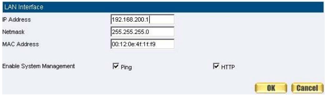
Figure3-1 Setting LAN Interface WebUI

The default LAN IP Address is 192.168.1.1. After the Administrator setting the
new LAN IP Address on the computer, he/she have to restart the System to make the new IP address effective. (when the computer obtain IP by DHCP)

Do not cancel WebUI selection before not setting Permitted IPs yet. It will cause
the Administrator cannot be allowed to enter the SMC BR21VPN's WebUI from LAN.
WAN
Setting WAN Interface Address
STEP 1. Select WAN in Interface and click Modify in WAN1 Interface.

The setting of WAN2 Interface is almost the same as WAN1. The difference is that WAN2 has a selection of Disable. The System Administrator can close WAN2 Interface by this selection. (Figure3-2)

Figure3-2 Disable WAN2 Interface
STEP 2 . Setting the Connection Service (ICMP or DNS way):
ICMP: Enter an Alive Indicator Site IP (can select from Assist) (Figure3-3)
DNS: Enter DNS Server IP Address and Domain Name (can select from Assist) (Figure3-4)
Setting time of seconds between sending alive packet.
WAN1 Interface
Service

Alive Indicator Site IP:
66.134.75.238
Assist

Figure3-3 ICMP Connection
seconds between the sending of each alive packet. (Range: 0 - 99, 0: do not check)
WAN1 Interface
Service

DNS Server IP Address:
24.30.199.7
Assist

seconds between the sending of each alive packet. (Range: 0 - 99, 0: do not check)

Figure 3-4 DNS Service
Connection test is used for SMC BR21VPN to detect if the WAN can connect or
not. So the Alive Indicator Site IP, DNS Server IP Address, or Domain Name must be able to use permanently. Or it will cause judgmental mistakes of the device.
STEP 3. Select the Connecting way:
PPPoE (ADSL User) (Figure3-5):
- Select PPPoE
- Enter User Name as an account
- Enter Password as the password
- Select Dynamic or Fixed in IP Address provided by ISP. If you select Fixed, please enter IP Address, Netmask, and Default Gateway.
- Enter Max. Downstream Bandwidth and Max. Upstream Bandwidth. (According to the flow that user apply)
- Select Ping and HTTP
- Click OK (Figure3-6)
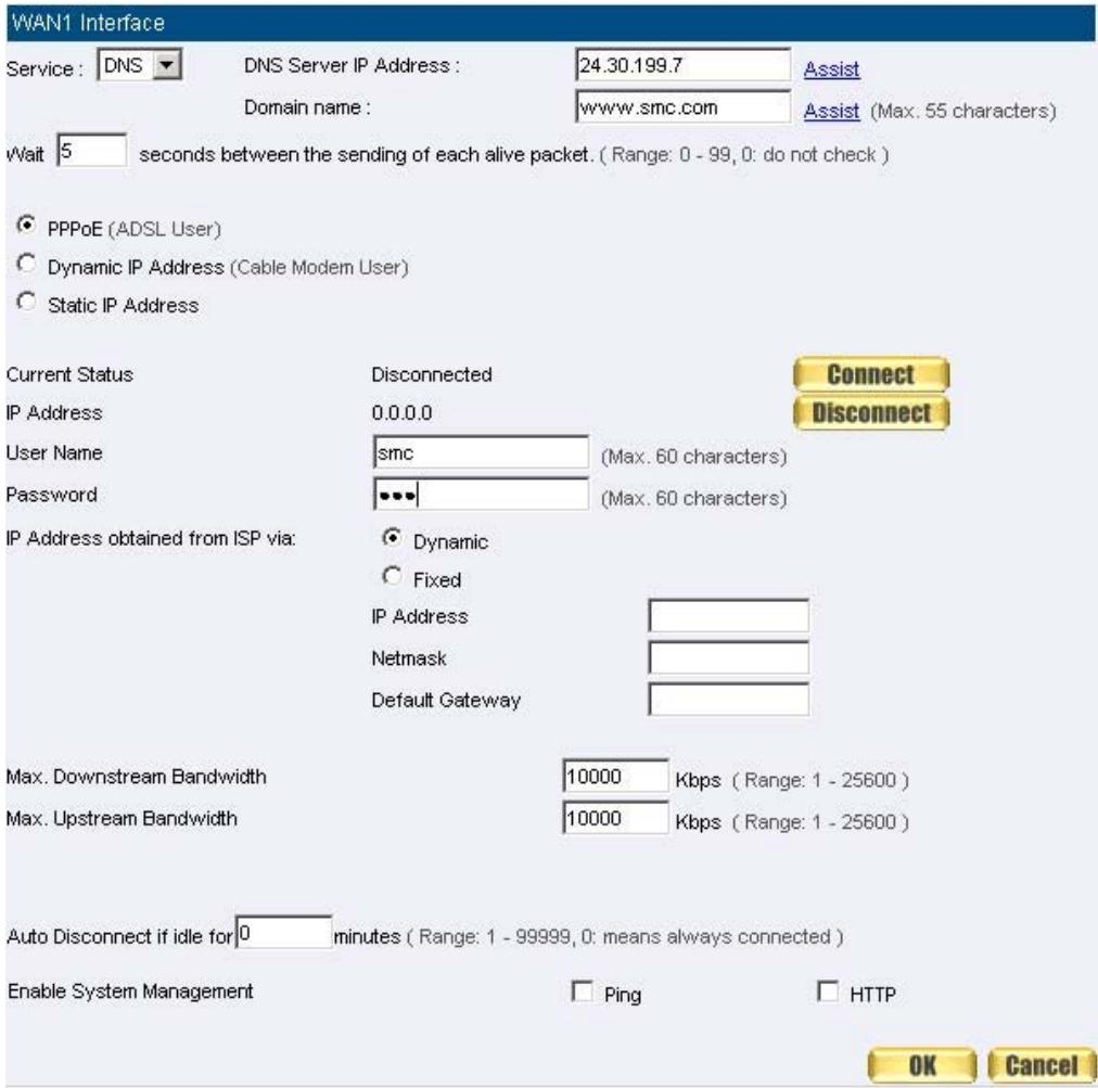
Figure3-5 PPPoE Connection

Figure3-6 Complete PPPoE Connection Setting

If the connection is PPPoE, you can choose Service-On-Demand for WAN
Interface to connect automatically when disconnect; or to set up Auto Disconnect if idle (not recommend)
Dynamic IP Address (Cable Modem User) (Figure3-7):
- Select Dynamic IP Address (Cable Modem User)
- Click Renew in the right side of IP Address and then can obtain IP automatically.
- If the MAC Address is required for ISP then click on Clone MAC Address to obtain MAC IP automatically.
- Hostname: Enter the hostname provided by ISP.
- Domain Name: Enter the domain name provided by ISP.
- User Name and Password are the IP distribution method according to Authentication way of DHCP+ protocol (like ISP in China)
- Enter Max. Downstream Bandwidth and Max. Upstream Bandwidth (According to the flow that user apply)
- Select Ping and HTTP
- Click OK (Figure3-8)
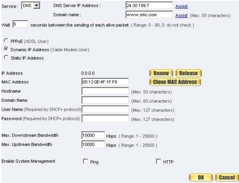
Figure3-7 Dynamic IP Address Connection

Figure3-8 Complete Dynamic IP Connection Setting
Static IP Address (Figure3-9)
- Select Static IP Address
- Enter IP Address, Netmask, and Default Gateway that provided by ISP
- Enter DNS Server1 and DNS Server2

In WAN2, the connecting of Static IP Address does not need to set DNS Server
- Enter Max. Downstream Bandwidth and Max. Upstream Bandwidth (According to the flow that user apply)
- Select Ping and HTTP
- Click OK (Figure3-10)
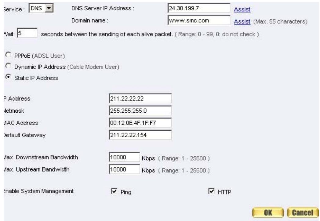
Figure3-9 Static IP Address Connection

Figure3-10 Complete Static IP Address Connection Setting

When selecting Ping and WebUI on WAN network Interface, users will be able to
ping the SMC BR21VPN and enter the WebUI WAN network. It may influence network security. The suggestion is to Cancel Ping and WebUI after all the settings have finished. And if the System Administrator needs to enter UI from WAN, he/she can use Permitted IPs to enter.
DMZ
Setting DMZ Interface Address (NAT Mode)
STEP1. Click DMZ Interface
STEP 2 . Select NAT Mode in DMZ Interface
Select NAT in DMZ Interface
Enter IP Address and Netmask
STEP 3 . Select Ping and HTTP
STEP 4 . Click OK (Figure3-11)
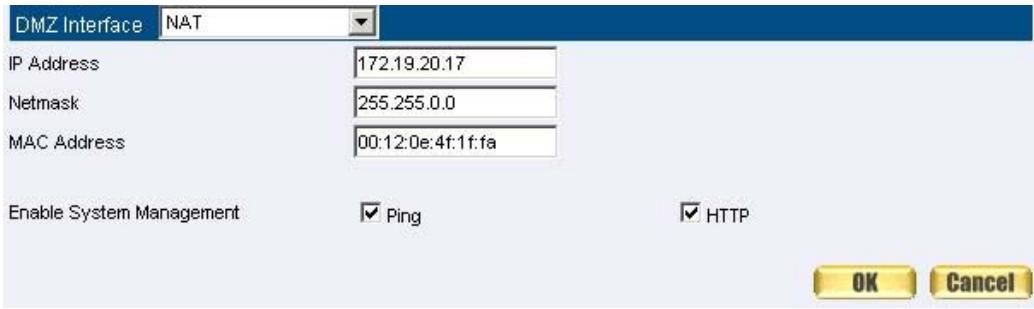
Figure3-11 Setting DMZ Interface Address (NAT Mode) WebUI
Setting DMZ Interface Address (Transparent Mode)
STEP 1. Select DMZ Interface
STEP 2. Select Transparent Mode in DMZ Interface
Select DMZ_Transparent in DMZ Interface
STEP 1. Select Ping and HTTP
STEP 2 . Click OK (Figure3-12)

Figure 3-12 Setting DMZ Interface Address (Transparent Mode) WebUI

In WAN, the connecting way must be Static IP Address and can choose
Transparent Mode in DMZ.
Chapter 4 Address
Address
The SMC BR21VPN allows the Administrator to set Interface addresses of the LAN network, LAN network group, WAN network, WAN network group, DMZ and DMZ group.
An IP address in the Address Table can be an address of a computer or a sub network. The Administrator can assign an easily recognized name to an IP address. Based on the network it belongs to, an IP address can be an LAN IP address, WAN IP address or DMZ IP address. If the Administrator needs to create a control policy for packets of different IP addresses, he can first add a new group in the LAN Group or the WAN Group and assign those IP addresses into the newly created group. Using group addresses can greatly simplify the process of building control policies.

With easily recognized names of IP addresses and names of address groups ,
shown in the address table, the Administrator can use these names as the source address or destination address of control policies. The address table should be setup before creating control policies, so that the Administrator can pick the names of correct IP addresses from the address table when setting up control policies.
Define the required fields of Address
Name:
The System Administrator set up a name as IP Address that is easily recognized.
IP Address:
It can be a PC's IP Address or several IP Address of Subnet. Different network area can be: Internal IP Address, External IP Address, and DMZ IP Address.
Netmask:
When correspond to a specific IP, it should be set as: 255.255.255.255.
When correspond to several IP of a specific Domain. Take 192.168.100.1 (C Class subnet) as an example, it should be set as: 255.255.255.0.
MAC Address:
Correspond a specific PC's MAC Address to its IP; it can prevent users changing IP and accessing to the net service through policy without authorizing.
Get Static IP address from DHCP Server:
- When enable this function and then the IP obtain from DHCP Server automatically under LAN or DMZ will be distributed to the IP that correspond to the MAC Address.
We set up two Address examples in this chapter:
| No | Suitable Situation | Example | Page |
| Ex1 | LAN | Under DHCP circumstances, assign the specific IP to static users and restrict them to access FTP net service only through policy. | 55 |
| Ex2 | LAN Group WAN | Set up a policy that only allows partial users to connect with specific IP (External Specific IP) | 58 |
Example
Under DHCP situation, assign the specific IP to static users and restrict them to access FTP net service only through policy
STEP 1. Select LAN in Address and enter the following settings:
- Click New Entry button (Figure4-1)
Name: Enter Rayearth
IP Address: Enter 192.168.3.2
Netmask: Enter 255.255.255.255
MAC Address: Enter the user's MAC Address (00:B0:18:25:F5:89)
Select Get static IP address from DHCP Server - Click OK (Figure4-2)
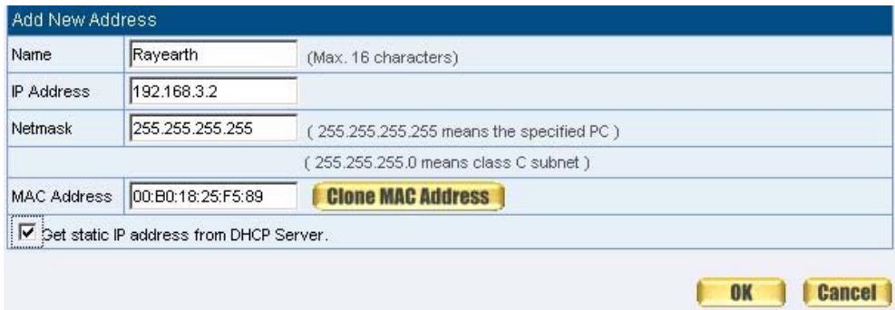
Figure 4-1 Setting LAN Address Book WebUI
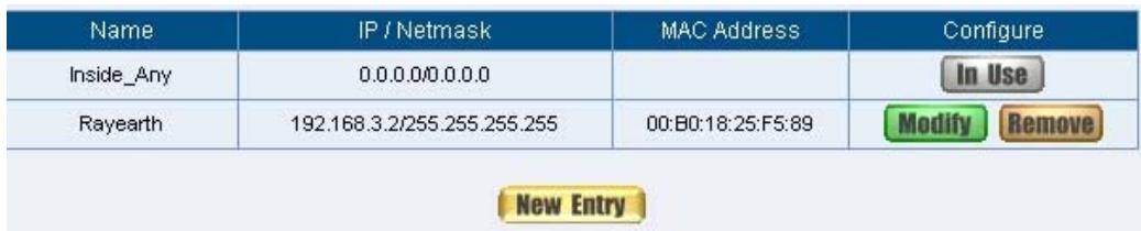
Figure4-2 Complete the Setting of LAN
STEP 2 . Adding the following setting in Outgoing Policy: (Figure4-3)
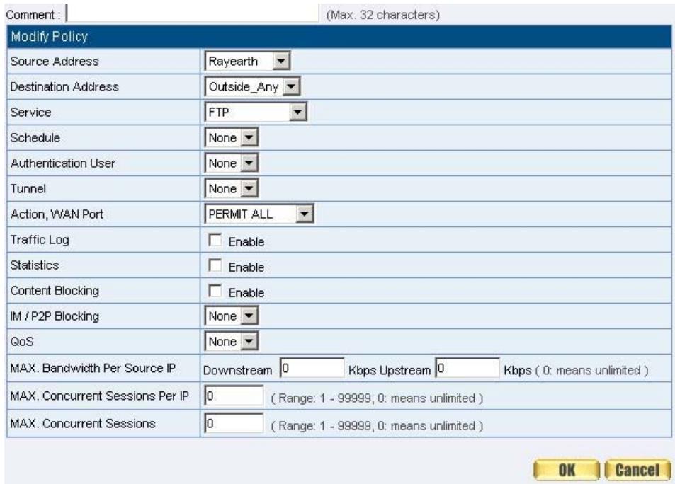
Figure 4-3 Add a Policy of Restricting the Specific IP to Access to Internet
STEP 3 . Complete assigning the specific IP to static users in Outgoing Policy and restrict them to access FTP net service only through policy: (Figure4-4)

Figure 4-4 Complete the Policy of Restricting the Specific IP to Access to Internet

When the System Administrator setting the Address Book, he/she can choose
the way of clicking on Clone MAC Address to make the SMC BR21VPN to fill out the user's MAC Address automatically.

In LAN of Address function, the SMC BR21VPN will default an Inside Any
address represents the whole LAN network automatically. Others like WAN, DMZ also have the Outside Any and DMZ Any default address setting to represent the whole subnet.

The setting mode of WAN and DMZ of Address are the same as LAN; the only
difference is WAN cannot set up MAC Address.
Setup a policy that only allows partial users to connect with specific IP (External Specific IP)
STEP 1 . Setting several LAN network Address. (Figure4-5)
| Name | IP / Netmask | MAC Address | Configure |
| Inside_Any | 0.0.0.0/0.0.0.0 | In Use | |
| Rayearth | 192.168.3.2/255.255.255.255 | 00:B0:18:25:F5:89 | In Use |
| josh | 192.168.1.3/255.255.255.255 | In Use | |
| colin | 192.168.1.4/255.255.255.255 | In Use |
Figure4-5 Setting Several LAN Network Address
STEP 2. Enter the following settings in LAN Group of Address:
- Click New Entry (Figure 4-6)
Enter the Name of the group - Select the users in the Available Address column and click Add
- Click OK (Figure 4-7)
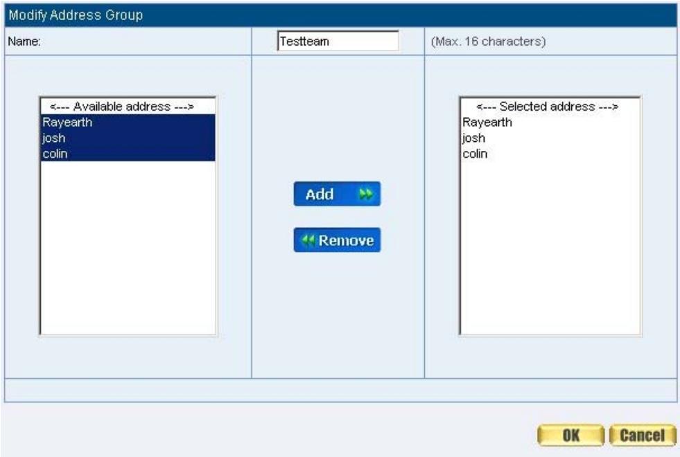

Figure4-6 Add New LAN Address Group
Figure4-7 Complete Adding LAN Address Group

The setting mode of WAN Group and DMZ Group of Address are the same as Group.
STEP 3. Enter the following settings in WAN of Address function:
- Click New Entry (Figure4-8)
Enter the following data (Name, IP Address, Netmask) - Click OK (Figure4-9)
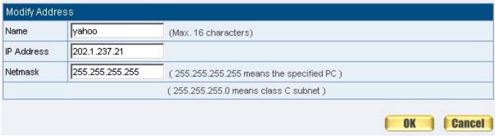
Figure4-8 Add New WAN Address

Figure4-9 Complete the Setting of WAN Address
STEP 4. To exercise STEP1~3 in Policy (Figure4-10, 4-11)
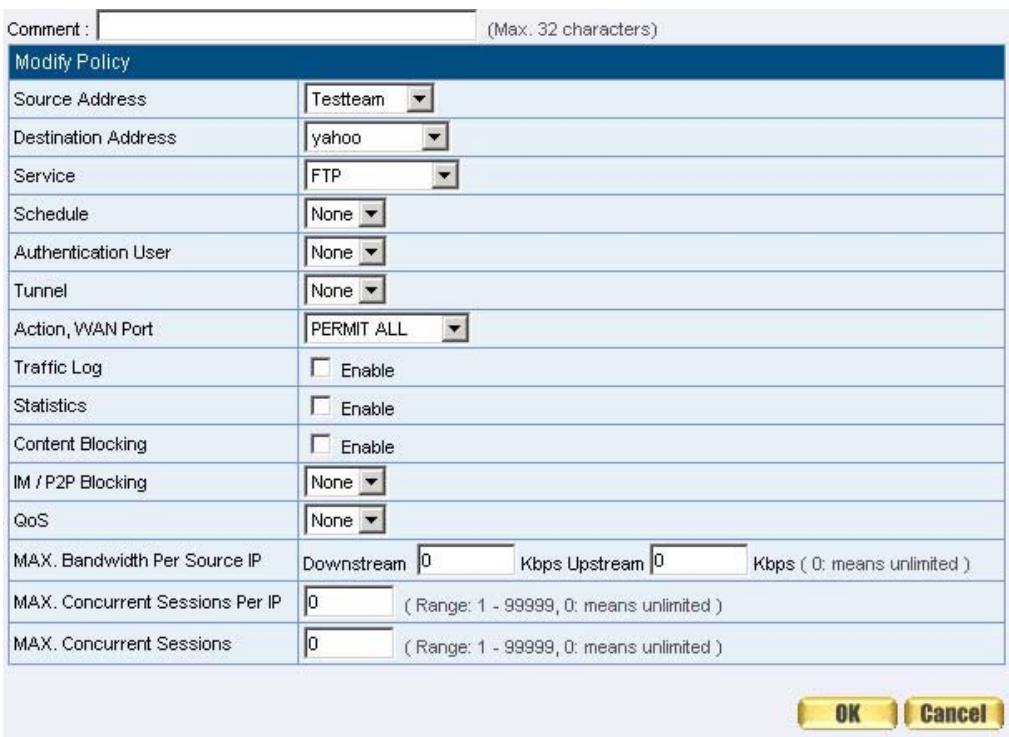
Figure4-10 To Exercise Address Setting in Policy

Figure4-11 Complete the Policy Setting

The Address function really take effect only if use with Policy.
Chapter 5 Service
Service
TCP and UDP protocols support varieties of services, and each service consists of a TCP Port or UDP port number, such as TELNET (23), SMTP (21), SMTP (25), POP3 (110), etc. The SMC BR21VPN includes two services: Pre-defined Service and Custom Service.
The common-use services like TCP and UDP are defined in the Pre-defined Service and cannot be modified or removed. In the custom menu, users can define other TCP port and UDP port numbers that are not in the pre-defined menu according to their needs. When defining custom services, the client port ranges from 1024 to 65535 and the server port ranges from 0 to 65535
In this chapter, network services are defined and new network services can be added. There are three sub menus under Service which are: Pre-defined, Custom, and Group. The Administrator can simply follow the instructions below to define the protocols and port numbers for network communication applications. Users then can connect to servers and other computers through these available network services.

How to use Service?
The Administrator can add new service group names in the Group option under Service menu, and assign desired services into that new group. Using service group the Administrator can simplify the processes of setting up control policies. For example, there are 10 different computers that want to access 5 different services on a server, such as HTTP, FTP, SMTP, POP3, and TELNET. Without the help of service groups, the Administrator needs to set up 50 (10x5) control policies, but by applying all 5 services to a single group name in the Service field,
it takes only one control policy to achieve the same effect as the 50 control policies.
Define the required fields of Service
Pre-defined WebUI's Chart and Illustration:
| Chart | Illustration |
| ANY | Any Service |
| TCP | TCP Service, For example: FTP, FINGER, HTTP, HTTPS, IMAP, SMTP, POP3, ANY, AOL, BGP, GOPHER, Inter Locator, IRC, L2TP, LDAP, NetMeeting, NNTP, PPTP, Real Media, RLOGIN, SSH, TCP ANY, TELNET, VDO Live, WAIS, WINFRAME, X-WINDOWS, ...etc. |
| UDP | UDP Service, For example: IKE, DNS, NTP, IRC, RIP, SNMP, SYSLOG, TALK, TFTP, UDP-ANY, UUCP,...etc. |
| ICMP | ICMP Service, Foe example: PING, TRACEROUTE...etc. |
New Service Name:
The System Manager can name the custom service.
Protocol:
The protocol type to be used in connection for device, such as TCP and UDP mode
Client Port:
The port number of network card of clients. (The range is 1024~65535, suggest to use the default range)
Server Port:
The port number of custom service
| No | Suitable Situation | Example | Page |
| Ex1 | Custom | Allow external user to communicate with internal user by VoIP through policy. (VoIP Port: TCP 1720, TCP 15325-15333, UDP 15325-15333) | 65 |
| Ex2 | Group | Setting service group and restrict the specific users only can access to service resource that provided by this group through policy. (Group: HTTP, POP3, SMTP, DNS) | 69 |
Custom
Allow external user to communicate with internal user by VoIP through policy. (VoIP Port: TCP 1720, TCP 15328-15333, UDP 15328-15333)
STEP 1 . Set LAN and LAN Group in Address function as follows: (Figure5-1, 5-2)
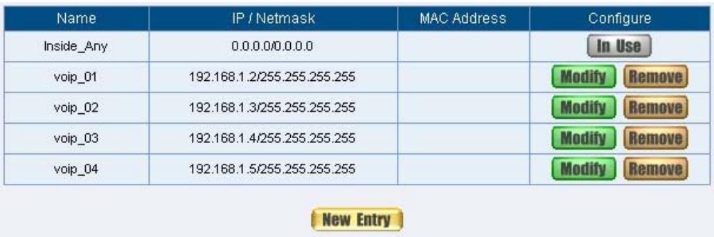
Figure5-1 Setting LAN Address Book WebUI

Figure5-2 Setting LAN Group Address Book WebUI
STEP 2 . Enter the following setting in Custom of Service function:
- Click New Entry (Figure5-3)
Service Name: Enter the preset name VoIP
Protocol#1 select TCP, need not to change the Client Port, and set the Server Port as: 1720:1720
Protocol#2 select TCP, need not to change the Client Port, and set the Server Port as: 15328:15333
Protocol#3 select UDP, need not to change the Client Port, and set the Server Port as: 15328:15333 - Click OK (Figure5-4)
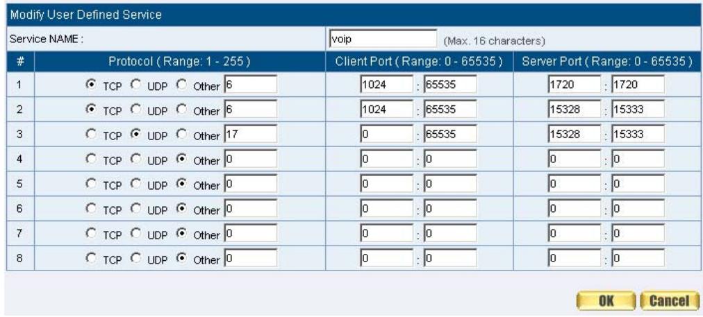

Figure5-3 Add User Define Service
Figure5-4 Complete the Setting of User Define Service of VoIP
If the port numbers that enter in the two spaces are different port number, then enable the port number under the range between the two different port numbers (for example: 15328:15333). And if the port number that enter in the two space are the same port number, then enable the port number as one (for example: 1720:1720).
STEP 3. Compare Service to Virtual Server. (Figure5-5)
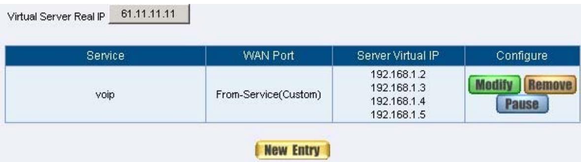
Figure5-5 Compare Service to Virtual Server
STEP 4 . Compare Virtual Server to Incoming Policy. (Figure5-6)

Figure5-6 Complete the Policy for External VoIP to Connect with Internal VoIP
STEP 5. In Outgoing Policy, complete the setting of internal users using VoIP to connect with external network VoIP: (Figure5-7)

Figure5-7 Complete the Policy for Internal VoIP to Connect with External VoIP

Service must cooperate with Policy and Virtual Server that the function can take
effect
Group
Setting service group and restrict the specific users only can access to service resource that provided by this group through policy (Group: HTTP, POP3, SMTP, DNS)
STEP 1 . Enter the following setting in Group of Service:
■ Click New Entry (Figure 5-8)
Name: Enter Main_Service
Select HTTP, POP3, SMTP, DNS in Available Service and click Add
- Click OK (Figure 5-9)
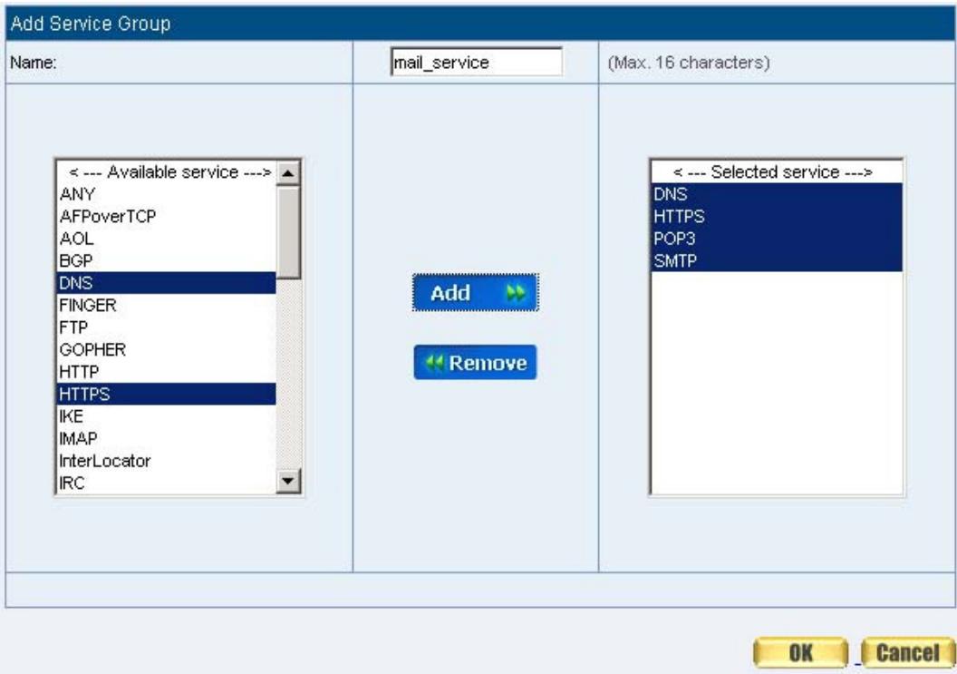
Figure5-8 Add Service Group

Figure5-9 Complete the setting of Adding Service Group

f you want to remove the service you choose from Selected Service, choose the
service you want to delete and click Remove.
STEP 2. In LAN Group of Address function, Setting an Address Group that can include the service of access to Internet. (Figure5-10)
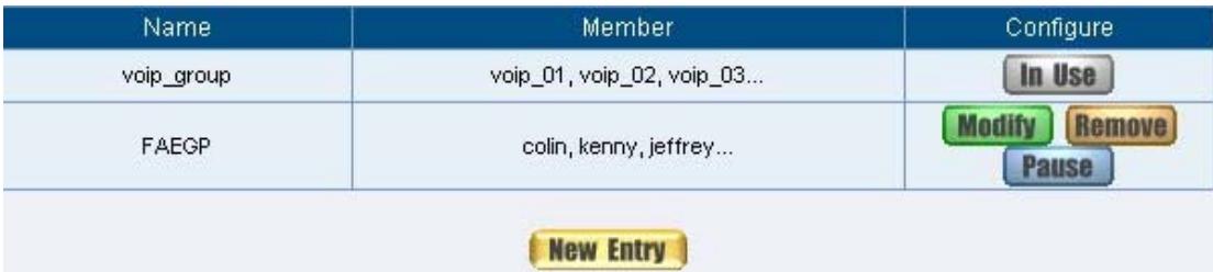
Figure5-10 Setting Address Book Group
STEP 3 . Compare Service Group to Outgoing Policy. (Figure5-11)

Figure5-11 Setting Policy
Chapter 6 Schedule
Schedule
In this chapter, the SMC BR21VPN provides the Administrator to configure a schedule for policy to take effect and allow the policies to be used at those designated times. And then the Administrator can set the start time and stop time or VPN connection in Policy or VPN. By using the Schedule function, the Administrator can save a lot of management time and make the network system most effective.

How to use the Schedule?
The system Administrator can use schedule to set up the device to carry out the connection of Policy or VPN during several different time division automatically.
Example
To configure the valid time periods for LAN users to access to Internet in a day
STEP 1. Enter the following in Schedule:
- Click New Entry (Figure6-1)
Enter Schedule Name
Set up the working time of Schedule for each day - Click OK (Figure6-2)
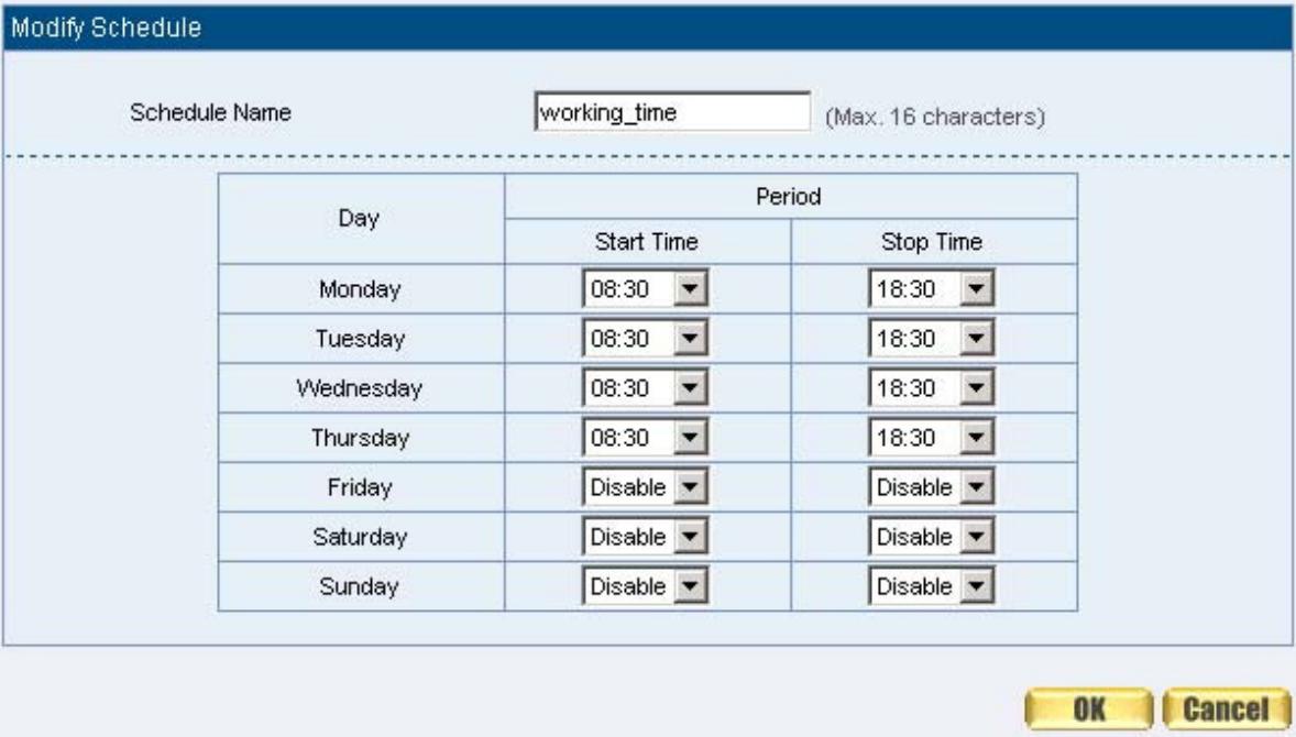
Figure6-1 Setting Schedule WebUI

Figure6-2 Complete the Setting of Schedule
STEP 2 . Compare Schedule with Outgoing Policy (Figure6-3)

Figure6-3 Complete the Setting of Comparing Schedule with Policy

The Schedule must compare with Policy .
Chapter 7 QOS
QoS
By configuring the QoS, you can control the OutBound and InBound Upstream/Downstream Bandwidth. The administrator can configure the bandwidth according to the WAN bandwidth.
Downstream Bandwidth : To configure the Guaranteed Bandwidth and Maximum Bandwidth.
Upstream Bandwidth : To configure the Guaranteed Bandwidth and Maximum Bandwidth.
QoS Priority : To configure the priority of distributing Upstream/Downstream and unused bandwidth.
The SMC BR21VPN configures the bandwidth by different QoS, and selects the suitable QoS through Policy to control and efficiently distribute bandwidth. The SMC BR21VPN also makes it convenient for the administrator to make the Bandwidth to reach the best utility. (Figure7-1, 7-2)
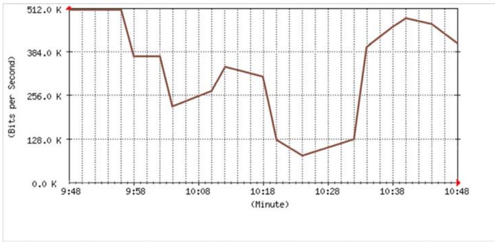
Figure7-1 the Flow Before Using QoS
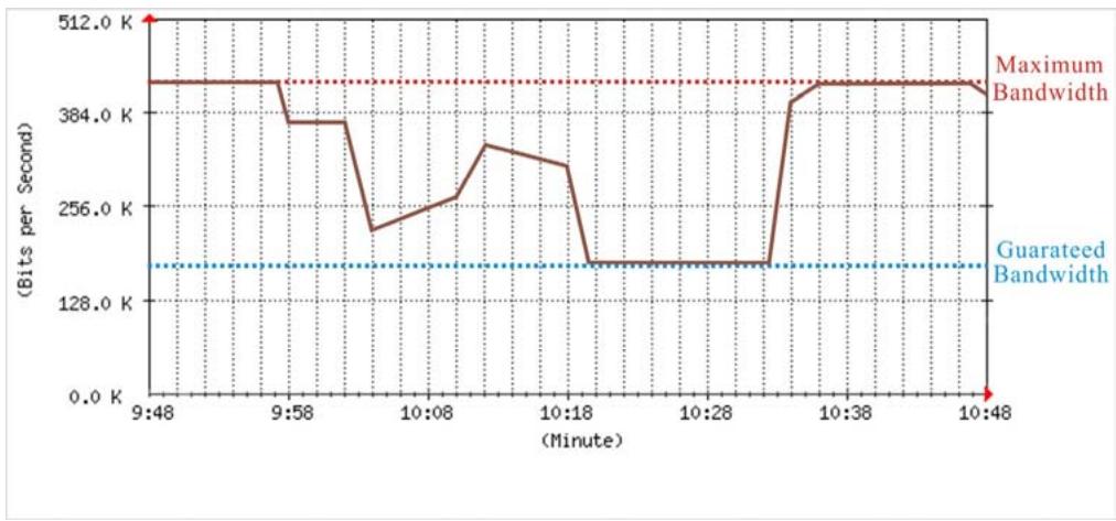
Figure7-2 the Flow After Using QoS (Max. Bandwidth: 400Kbps, Guaranteed Bandwidth: 200Kbps)
Define the required fields of QoS
WAN:
Display WAN1 and WAN2
Downstream Bandwidth:
To configure the Guaranteed Bandwidth and Maximum Bandwidth according to the bandwidth range you apply from ISP
Upstream Bandwidth:
To configure the Guaranteed Bandwidth and Maximum Bandwidth according to the bandwidth range you apply from ISP
Priority:
To configure the priority of distributing Upstream/Downstream and unused bandwidth.
Guaranteed Bandwidth:
The basic bandwidth of QoS. The connection that uses the IPSec Autokey of VPN or Policy will preserve the basic bandwidth.
Maximum Bandwidth:
The maximum bandwidth of QoS. The connection that uses the IPSec Autokey of VPN or Policy, which bandwidth will not exceed the amount you set.
We set up two QoS examples in this chapter:
| No | Suitable Situation | Example | Page |
| Ex1 | QoS | Setting a policy that can restrict the user's downstream and upstream bandwidth. | 79 |
Example
Setting a policy that can restrict the user's downstream and upstream bandwidth
STEP 1. Enter the following settings in QoS:
- Click New Entry (Figure7-3)
| Name | WAN | Downstream Bandwidth | Upstream Bandwidth | Priority | Configure | ||
| policy_GOS | 1 | G.Bandwidth = 200 Kbps | G.Bandwidth = 200 Kbps | Middle | ModifyRemove | ||
| M.Bandwidth = 400 Kbps | M.Bandwidth = 400 Kbps | ||||||
| 2 | G.Bandwidth = 300 Kbps | G.Bandwidth = 24 Kbps | |||||
| M.Bandwidth = 400 Kbps | M.Bandwidth = 64 Kbps | ||||||
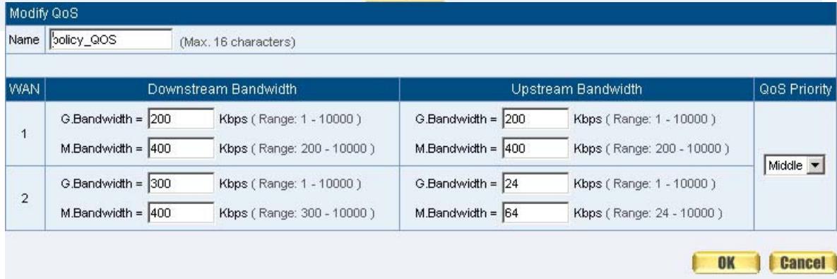
Figure7-3 QoS WebUI Setting
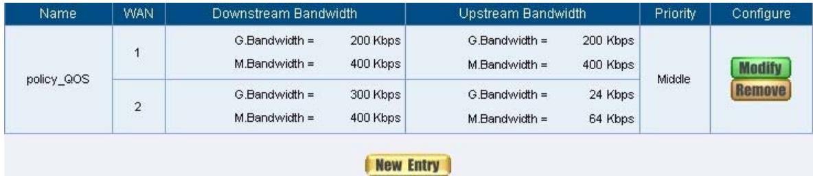
Figure7-4 Complete the QoS Setting
STEP 2 . Use the QoS that set by STEP1 in Outgoing Policy. (Figure7-5, 7-6)

Figure7-5 Setting the QoS in Policy

Figure7-6 Complete Policy Setting

When the administrator are setting QoS, the bandwidth range that can be set is the
value that system administrator set in the WAN of Interface. So when the System
Administrator sets the downstream and upstream bandwidth in WAN of Interface,
he/she must set up precisely.
Chapter 8 Authentication
Authentication
By configuring the Authentication, you can control the user's connection authority. The user has to pass the authentication to access to Internet.
The SMC BR21VPN configures the authentication of LAN's user by setting account and password to identify the privilege.
Authentication Management
■ Provide the Administrator the port number and valid time to setup SMC BR21VPN authentication. (Have to setup the Authentication first)
Authentication Port: The internal user have to pass the authentication to access to the Internet when enable SMC BR21VPN.
Re-Login if Idle: When the internal user access to Internet, can setup the idle time after passing authentication. If idle time exceeds the time you setup, the authentication will be invalid. The default value is 30 minutes.
URL to redirect when authentication succeed: The user who had passes Authentication have to connect to the specific website. (It will connect to the website directly which the user want to login) The default value is blank.
Messages to display when user login: It will display the login message in the authentication WebUI. (Support HTML) The default value is blank (display no message in authentication WebUI)
- Add the following setting in this function: (Figure8-1)
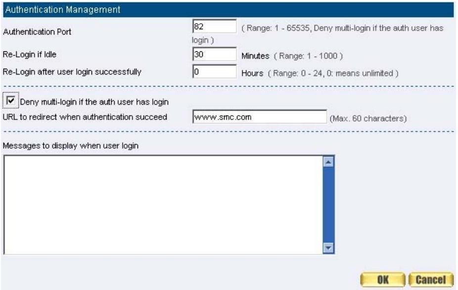
Figure8-1 Authentication Setting WebUI
- When the user connect to external network by Authentication, the following page will be displayed: (Figure8-2)
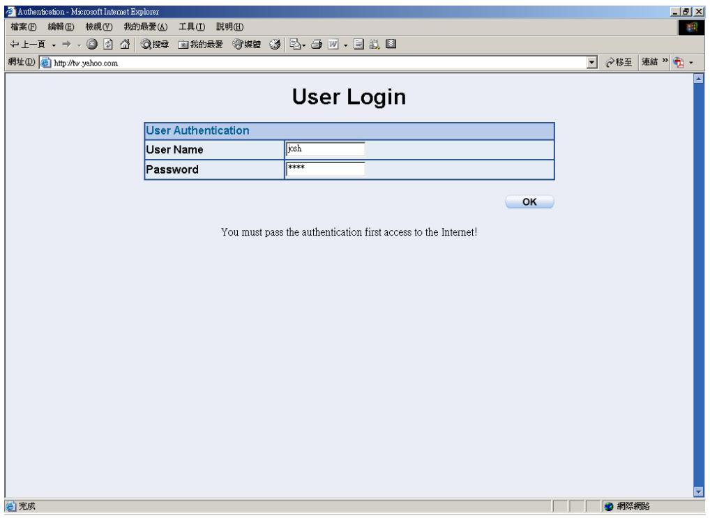
Figure8-2 Authentication Login WebUI
It will connect to the appointed website after passing Authentication: (Figure8-3)
Figure8-3 Connecting to the Appointed Website After Authentication

Authentication port number. And then the Authentication WebUI will be displayed.
Auth-User Name:
The user account for Authentication you want to set.
Password:
The password when setting up Authentication.
Confirm Password:
Enter the password that correspond to Password
We set up four Authentication examples in this chapter:
| No | Suitable Situation | Example | Page |
| Ex1 | Auth User Auth Group | Setting specific users to connect with external network only before passing the authentication of policy. (Adopt the built-in Auth User and Auth Group Function) | 87 |
Example
Setting specific users to connect with external network only before passing the authentication of policy.
(Adopt the built-in Auth User and Auth Group Function)
STEP 1 . Setup several Auth User in Authentication. (Figure8-4)
| Authentication User Name | Configure | |
| colin | Modify | Remove |
| jeffrey | Modify | Remove |
| kevin | Modify | Remove |
| New Entry | ||

Figure8-4 Setting Several Auth Users WebUI
To use Authentication, the DNS Server of the user's network card must be the
same as the LAN Interface Address of SMC BR21VPN.
STEP 2 . Add Auth User Group Setting in Authentication function and enter the following settings:
Click New Entry
Name: Enter laboratory
Select the Auth User you want and Add to Selected Auth User
Click OK
Complete the setting of Auth User Group (Figure8-5)
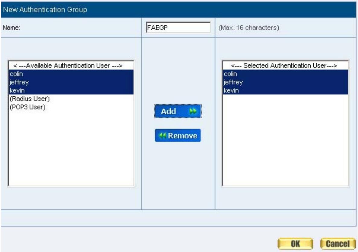
Figure8-5 Setting Auth Group WebUI
STEP 3. Add a policy in Outgoing Policy and input the Address and Authentication of STEP 2 (Figure8-6, 8-7)
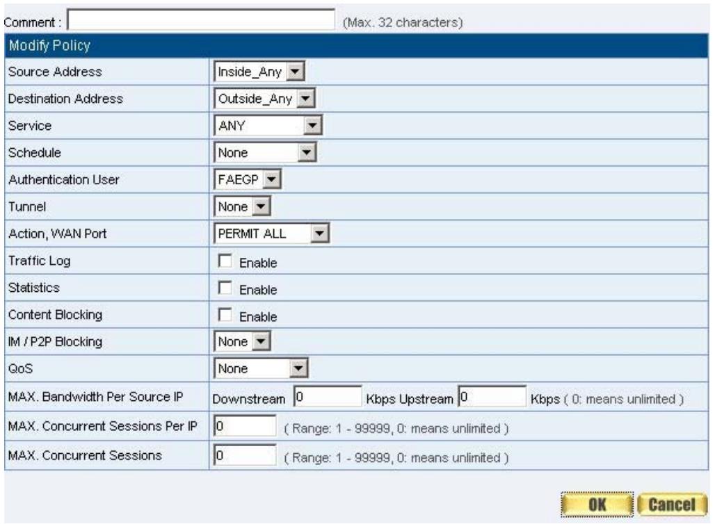
Figure8-6 Auth-User Policy Setting

Figure8-7 Complete the Policy Setting of Auth-User
STEP 4 . When user is going to access to Internet through browser, the authentication UI will appear in Browser. After entering the correct user name and password, click OK to access to Internet. (Figure8-8)
STEP 5 . If the user does not need to access to Internet anymore and is going to logout, he/she can click LOGOUT Auth-User to logout the system. Or enter theLogout Authentication WebUI (http:// LAN Interface: Authentication port number/ logout.html) to logout (Figure8-9)
User Login
User Authentication
UserID
Password
OK
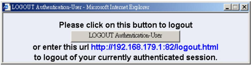
Figure8-8 Access to Internet through Authentication WebUI
Figure8-9LogoutAuth-UserWebUI
Chapter 9 Content Blocking
Content Filtering
【URL Blocking】: The administrator can set up to “Allow” or “Restrict” entering the specific website by complete domain name, key words, and met character (\~and ).
【Script Blocking】: The access authority of Popup, ActiveX, Java, Cookies
【P2P Blocking】: The authority of sending files by eDonkey, eMule, Bit Torrent
【IM Blocking】: To restrict the authority of receiving video, file and message from MSN Messenger, Yahoo Messenger, ICQ, QQ.
【Download Blocking】: To restrict the authority of download specific sub-name file, audio, and some common video by http protocol directly.
Define the required fields of Content Blocking
URL String:
The domain name that restricts to enter or only allow entering.
Popup Blocking:
Prevent the pop-up WebUI appearing
ActiveX Blocking:
Prevent ActiveX packets
Java Blocking:
Prevent Java packets
Cookies Blocking:
Prevent Cookies packets
eDonkey Blocking:
Prevent users to deliver files by eDonkey and eMule
BitTorrent Blocking:
Prevent users to deliver files by BitTorrent
WinMX:
Prevent users to deliver files by WinMX
IM Blocking:
Prevent users to login MSN Messenger, Yahoo Messenger, ICQ, QQ, and Skype
Audio and Video Types:
Prevent users to transfer sounds and video file by http
Sub-name file Blocking:
Prevent users to deliver specific sub-name file by http
All Type:
Prevent users to send the Audio, Video types, and sub-name file...etc. by http protocol.
| No | Suitable Situation | Example | Page |
| Ex1 | URL Blocking | Restrict the Internal Users only can access to some specific Website | 95 |
| Ex2 | Script Blocking | Restrict the Internal Users to access to Script file of Website. | 98 |
| Ex3 | P2P Blocking | Restrict the Internal Users to access to the file on Internet by P2P. | 100 |
| Ex4 | IM Blocking | Restrict the Internal Users to send message, files, video and audio by Instant Messaging. | 102 |
| Ex5 | Download Blocking | Restrict the Internal Users to access to video, audio, and some specific sub-name file from http or ftp protocol directly. | 104 |
URL
Restrict the Internal Users only can access to some specific Website
URL Blocking:
Symbol: ~ means open up; * means metacharacter
Restrict not to enter specific website: Enter the complete domain name or key word of the website you want to restrict in URL String.
For example: www.kcg.gov.tw or gov.
Only open specific website to enter:
- Add the website you want to open up in URL String. While adding, you must enter the symbol “~” in front of the ‘complete domain name’ or ‘key word’ that represents to open these website to enter’. For example: ~www.kcg.gov.tw or ~gov.
- After setting up the website you want to open up, enter an order to "forbid all" in the last URL String; means only enter * in URL String.

Warning! The order to forbid all must be placed at last forever. If you want to open
a new website, you must delete the order of forbidding all and then enter the new domain name. At last, re-enter the "forbid all" order again.
STEP 1. Enter the following in URL of Content Filtering function:
- Click New Entry
URL String: Enter ~yahoo, and click OK - Click New Entry
URL String: Enter ~google, and click OK - Click New Entry
URL String: Enter *, and click OK
Complete setting a URL Blocking policy (Figure9-1)
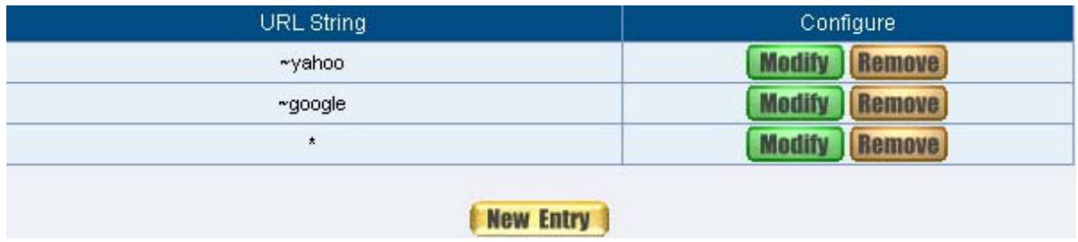
Figure9-1 Content Filtering Table
STEP 2. Add a Outgoing Policy and use in Content Blocking function: (Figure9-2)
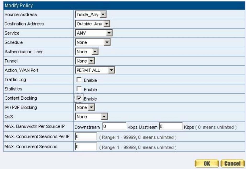
Figure3-2 ORL BIOLIMING Fuilty Settling
STEP 3 . Complete the policy of permitting the internal users only can access to some specific website in Outgoing Policy function: (Figure9-3)

Figure9-3 Complete Policy Settings

Afterwards the users only can browse the website that include "yahoo" and "gle" in domain name by the above policy.
SCRIPT
Restrict the Internal Users to access to Script file of Website
STEP 1 . Select the following data in Script of Content Blocking function:
Select Popup Blocking
Select ActiveX Blocking
Select Java Blocking
Select Cookies Blocking
Click OK
Complete the setting of Script Blocking (Figure9-4)

Figure9-4 Script Blocking WebUI
STEP 2 . Add a new Outgoing Policy and use in Content Blocking function: (Figure9-5)
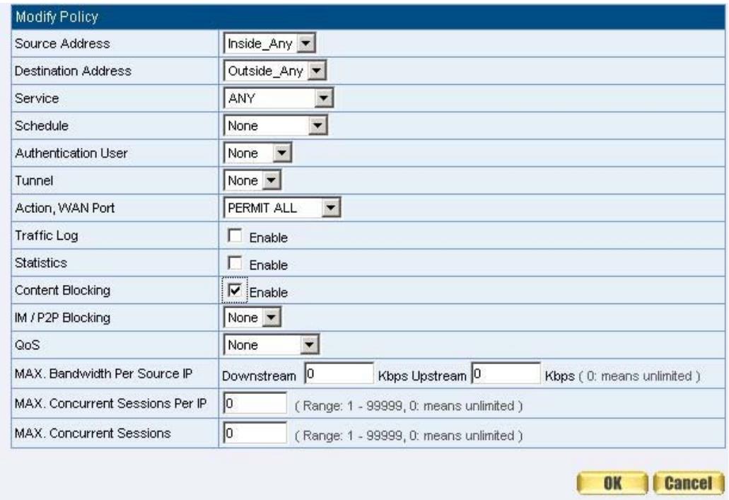
Figure9-5 New Policy of Script Blocking Setting
STEP 3 . Complete the policy of restricting the internal users to access to Script file of Website in Outgoing Policy: (Figure9-6)

Figure9-6 Complete Script Blocking Policy Setting

The users may not use the specific function (like JAVA, cookie...etc.) to browse the site through this policy. It can forbid the user browsing stock exchange ite...etc.
Download
Restrict the Internal Users to access to video, audio, and some specific sub-name file from http or ftp protocol directly
STEP 1. Enter the following settings in Download of Content Blocking function:
Select All Types Blocking
Click OK
Complete the setting of Download Blocking. (Figure9-13)
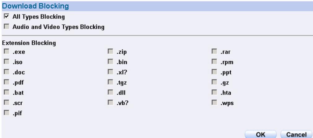
Figure9-13 Download Blocking WebUI
STEP 2 . Add a new Outgoing Policy and use in Content Blocking function:
(Figure9-14)
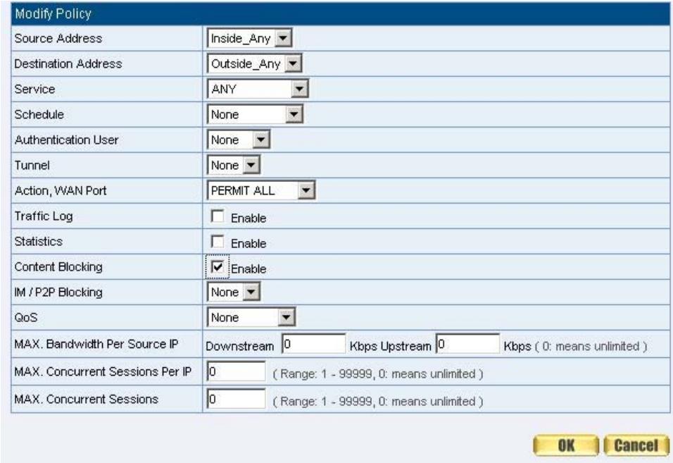
Figure9-14 Add New Download Blocking Policy Setting
STEP 3 . Complete the Outgoing Policy of restricting the internal users to access to video, audio, and some specific sub-name file by http protocol directly: (Figure9-15)

Figure9-15 Complete Download Blocking Policy Setting
Limit internal user access internet resources by P2P software.
Step1. In IM / P2P Blocking Setting, add the following settings:
■ Click New Entry. (Fig. 10-5)
Enter the Name of P2P_DBlocking.
- Select eDonkey, Bit Torrent, WinMX, Foxy, KuGoo, AppleJuice, AudioGalaxy, DirectConnect, iMesh and MUTE.
Click OK.
Complete the settings (Fig. 10-6)
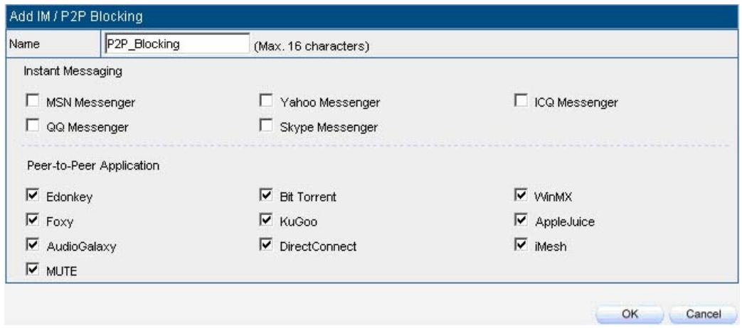
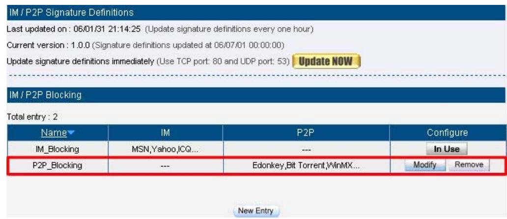
Fig. 10-5 P2P blocking setting
Fig. 10-6 Complete the P2P blocking setting
Step2. In Policy Outgoing, add one policy applied to P2P blocking setting. (Fig. 10-7)
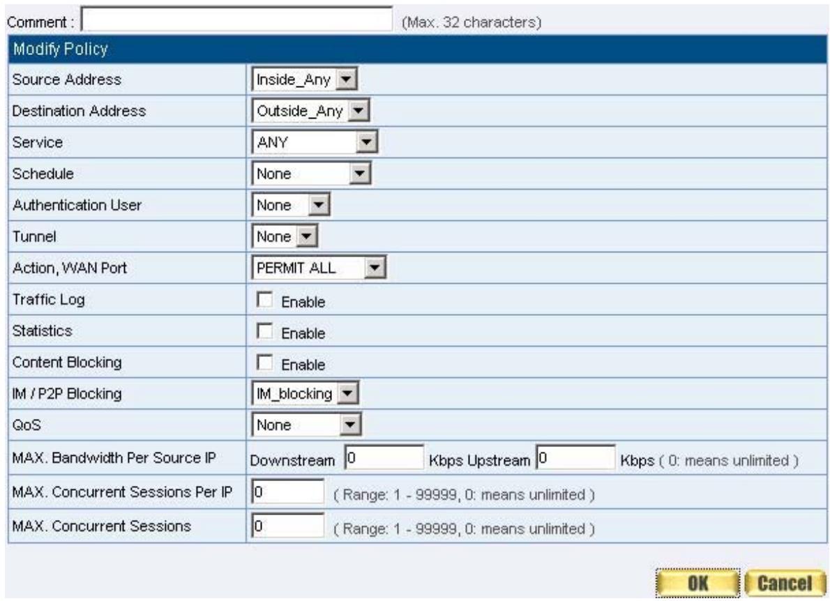
Fig. 10-7 Set the policy applied to P2P blocking
Step3. In Policy Outgoing, complete the policy setting of limit internal user to access internet resources by P2P software: (Fig. 10-8)

Fig. 10-8 Complete the Policy setting of P2P blocking
Chapter 10 Virtual Server
Virtual Server
The real IP address provided from ISP is always not enough for all the users when the system manager applies the network connection from ISP. Generally speaking, in order to allocate enough IP addresses for all computers, an enterprise assigns each computer a private IP address, and converts it into a real IP address through SMC BR21VPN's NAT (Network Address Translation) function. If a server that provides service to WAN network is located in LAN networks, external users cannot directly connect to the server by using the server's private IP address.
The SMC BR21VPN's Virtual Server function can solve this problem. A Virtual Server has set the real IP address of the SMC BR21VPN's WAN network interface to be the Virtual Server IP. Through the Virtual Server function, the SMC BR21VPN translates the Virtual Server's IP address into the private IP address in the LAN network.
Virtual Server owns another feature know as one-to-many mapping. This is when one real server IP address on the WAN interface can be mapped into four LAN network servers provide the same service private IP addresses. This option is useful for Load Balancing, which causes the Virtual Server to distribute data packets to each private IP addresses (which are the real servers) by session. Therefore, it can reduce the loading of a single server and lower the crash risk. And can improve the work efficiency.
In this chapter, we will have detailed introduction and instruction of Mapped IP and Server 1/2/3/4:
Mapped IP: Because the Intranet is transferring the private IP by NAT Mode (Network Address Translation). And if the server is in LAN, its IP Address is belonging to Private IP Address. Then the external users cannot connect to its private IP Address directly. The user must connect to the SMC BR21VPN's WAN subnet's Real IP and then map Real IP to Private IP of LAN by the SMC BR21VPN. It is a one-to-one mapping. That is, to map all the service of one WAN Real IP Address to one LAN Private IP Address.
Server 1/2/3/4: Its function resembles Mapped IP's. But the Virtual Server maps one to many. That is, to map a Real IP Address to 1~4 LAN Private IP Address and provide the service item in Service.
Define the required fields of Virtual Server
WAN IP :
WAN IP Address (Real IP Address)
Map to Virtual IP :
Map the WAN Real IP Address into the LAN Private IP Address
Virtual Server Real IP :
The WAN IP address which mapped by the Virtual Server.
Service name (Port Number) :
The service name that provided by the Virtual Server.
External Service Port :
The WAN Service Port that provided by the virtual server. If the service you choose only have one port and then you can change the port number here. (If change the port number to 8080 and then when the external users going to browse the Website; he/she must change the port number first to enter the Website.)
Server Virtual IP :
The virtual IP which mapped by the Virtual Server.
| No. | Suitable Situation | Example | Page |
| Ex1 | Mapped IP | Make a single server that provides several services such as FTP, Web, and Mail, to provide service by policy. | 110 |
| Ex2 | Virtual Server | Make several servers that provide a single service, to provide service through policy by Virtual Server. (Take Web service for example) | 113 |
| Ex3 | Virtual Server | The external user use VoIP to connect with VoIP of LAN. (VoIP Port: TCP 1720, TCP 15328-15333, UDP 15328-15333) | 116 |
| Ex4 | Virtual Server | Make several servers that provide several same services, to provide service through policy by Virtual Server. (Take HTTP, POP3, SMTP, and DNS Group for example) | 120 |
Preparation
Apply for two ADSL that have static IP (WAN1 static IP is 61.11.11.10~ 61.11.11.14) (WAN2 static IP is 211.22.22.18~ 211.22.22.30)
Example
Make a single server that provides several services such as FTP, Web, and Mail, to provide service by policy
STEP 1 . Setting a server that provide several services in LAN, and set up the network card's IP as 192.168.1.100. DNS is External DNS Server.
STEP 2. Enter the following setting in LAN of Address function: (Figure10-1)
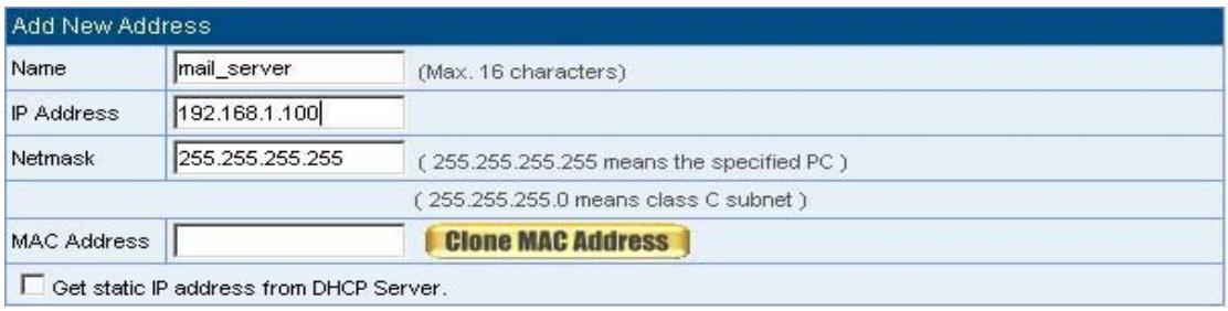
Figure10-1 Mapped IP Settings of Server in Address
STEP 3. Enter the following data in Mapped IP of Virtual Server function:
- Click New Entry
WAN IP: Enter 61.11.11.12 (click Assist for assistance)
Map to Virtual IP: Enter 192.168.1.100
Click OK
Complete the setting of adding new mapped IP (Figure10-2)
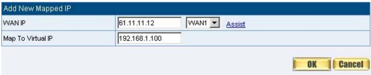
Figure10-2 Mapped IP Setting WebUI
STEP 4 . Group the services (DNS, FTP, HTTP, POP3, SMTP...) that provided and used by server in Service function. And add a new service group for server to send mails at the same time. (Figure10-3)

Figure10-3 Service Setting
STEP 5 . Add a policy that includes settings of STEP3, 4 in Incoming Policy. (Figure10-4)

Figure10-4 Complete the Incoming Policy
STEP 6 . Add a policy that includes STEP2, 4 in Outgoing Policy. It makes the server to send e-mail to external mail server by mail service. (Figure10-5)

Figure10-5 Complete the Outgoing Policy
STEP 7. Complete the setting of providing several services by mapped IP.
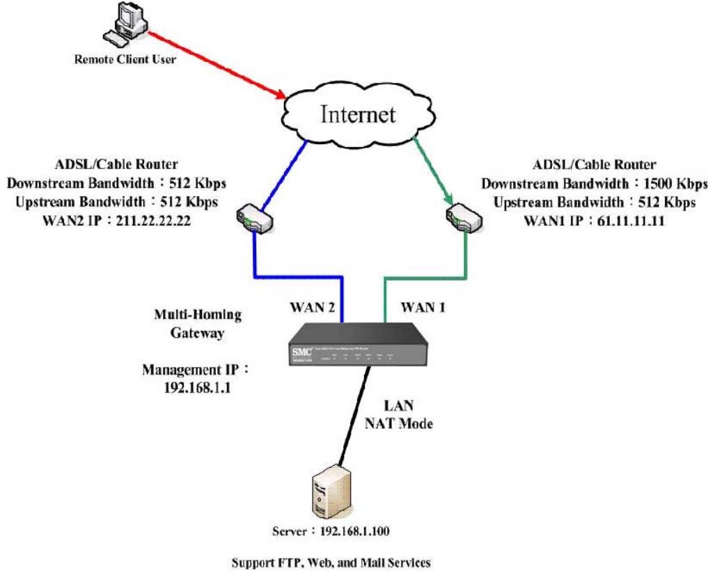
(Figure10-6)
Figure10-6 A Single Server that Provides Several Services by Mapped IP

Strong suggests not to choose ANY when setting Mapped IP and choosing
service. Otherwise the Mapped IP will be exposed to Internet easily and may be attacked by Hacker.
Make several servers that provide a single service, to provide service through policy by Virtual Server (Take Web service for example)
STEP 1 . Setting several servers that provide Web service in LAN network, which IP Address is 192.168.1.101, 192.168.1.102, 192.168.1.103, and 192.168.1.104
STEP 2. Enter the following data in Server 1 of Virtual Server function:
- Click the button next to Virtual Server Real IP ("click here to configure") in Server 1
■ Virtual Server Real IP: Enter 211.22.22.23 (click Assist for assistance) - Click OK (Figure10-7)

Figure10-7 Virtual Server Real IP Setting
- Click New Entry
Service: Select HTTP (80)
External Service Port: Change to 8080
Load Balance Server1: Enter 192.168.1.101
Load Balance Server2: Enter 192.168.1.102
Load Balance Server3: Enter 192.168.1.103
Load Balance Server4: Enter 192.168.1.104
Click OK
Complete the setting of Virtual Server (Figure10-8)
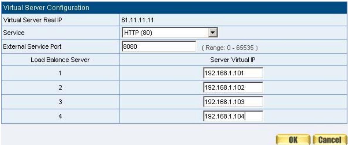
Figure10-8 Virtual Server Configuration WebUI
STEP 3 . Add a new policy in Incoming Policy, which includes the virtual server, set by STEP2. (Figure10-9)

Figure10-9 Complete Virtual Server Policy Setting

In this example, the external users must change its port number to 8080 before using the Website that set by the Web server.
STEP 4 . Complete the setting of providing a single service by virtual server. (Figure10-10)

Figure10-10 Several Servers Provide a Single Service by Virtual Server
The external user use VoIP to connect with VoIP of LAN (VoIP Port: TCP 1720, TCP 15328-15333, UDP 15328-15333)
STEP 1 . Set up VoIP in LAN network, and its IP is 192.168.1.100
STEP 2. Enter the following setting in LAN of Address function: (Figure10-11)
Figure10-11 Setting LAN Address WebUI
| Name | IP / Netmask | MAC Address | Configure |
| Inside_Any | 0.0.0.0/0.0.0.0 | In Use | |
| Voip | 192.168.1.100/255.255.255.255 | Modify Remove |
STEP 3. Add new VoIP service group in Custom of Service function. (Figure10-12)
Figure10-12 Add Custom Service
| Service name | Protocol | Client Port | Server Port | Configure |
| voip | TCP | 1024:65535 | 1720:1720 | Modify Remove |
STEP 4. Enter the following setting in Server1 of Virtual Server function:
- Click the button next to Virtual Server Real IP ("click here to configure") in Server1
■ Virtual Server Real IP: Enter 61.11.11.12 (click Assist for assistance) (Use WAN) - Click OK (Figure10-13)

Figure10-13 Virtual Server Real IP Setting WebUI
- Click New Entry
Service: Select (Custom Service) VoIP_Service
External Service Port: From-Service (Custom)
Load Balance Server1: Enter 192.168.1.100
Click OK
Complete the setting of Virtual Server (Figure10-14)
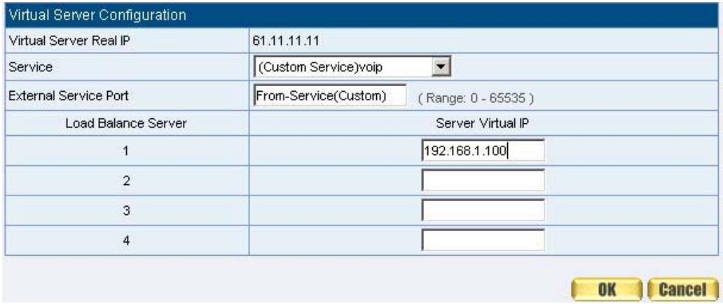
Figure10-14 Virtual Server Configuration WebUI

When the custom service only has one port number, then the external network port
of Virtual Server is changeable; On the contrary, if the custom service has more than one port network number, then the external network port of Virtual Server cannot be changed.
STEP 5. Add a new Incoming Policy, which includes the virtual server that set by STEP4: (Figure10-15)

Figure10-15 Complete the Policy includes Virtual Server Setting
STEP 6 . Enter the following setting of the internal users using VoIP to connect with external network VoIP in Outgoing Policy: (Figure10-16)

Figure10-16 Complete the Policy Setting of VoIP Connection
STEP 7. Complete the setting of the external/internal user using specific service to communicate with each other by Virtual Server. (Figure10-17)
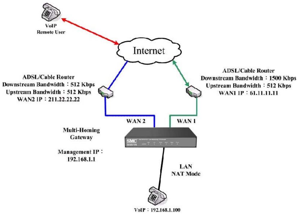
Figure10-17 Complete the Setting of the External/Internal User using specific service to communicate with each other by Virtual Server
Make several servers that provide several same services, to provide service through policy by Virtual Server. (Take HTTP, POP3, SMTP, and DNS Group for example)
STEP 1 . Setting several servers that provide several services in LAN network. Its network card's IP is 192.168.1.101, 192.168.1.102, 192.168.1.103, 192.168.1.104 and the DNS setting is External DNS server.
STEP 2. Enter the following in LAN and LAN Group of Address function: (Figure10-18, 10-19)
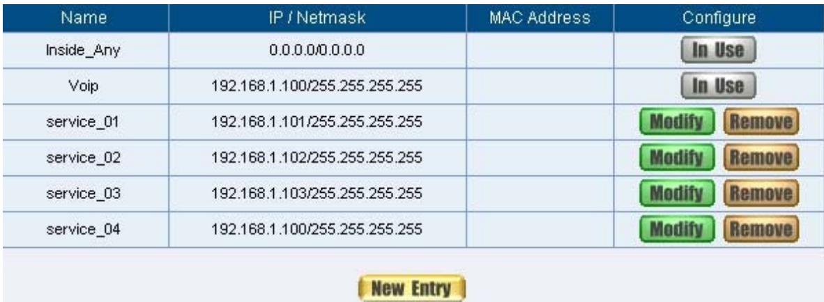
Figure10-18 Mapped IP Setting of Virtual Server in Address

Figure10-19 Group Setting of Virtual Server in Address
STEP 3 . Group the service of server in Custom of Service. Add a Service Group for server to send e-mail at the same time. (Figure10-20)

Figure10-20 Add New Service Group
STEP 4 . Enter the following data in Server1 of Virtual Server:
- Click the button next to Virtual Server Real IP ("click here to configure") in Server1
■ Virtual Server Real IP: Enter 211.22.22.23 (click Assist for assistance) - Click OK (Figure10-21)

Figure10-21 Virtual Server Real IP Setting
- Click New Entry
Service: Select (Group Service) Main_Service
External Service Port: From-Service (Group)
Enter the server IP in Load Balance Server
Click OK
Complete the setting of Virtual Server (Figure10-22)
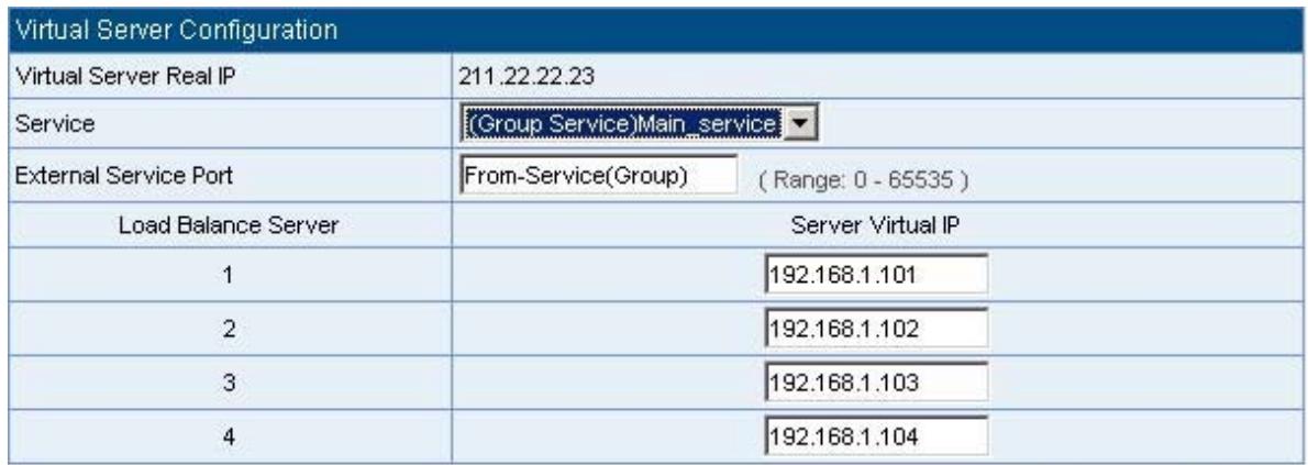

Figure10-22 Virtual Server Configuration WebUI
STEP 5. Add a new Incoming Policy, which includes the virtual server that set by STEP 3: (Figure10-23)

Figure10-23 Complete Incoming Policy Setting
STEP 6 . Add a new policy that includes the settings of STEP2, 3 in Outgoing Policy. It makes server can send e-mail to external mail server by mail service. (Figure10-24)

Figure10-24 Complete Outgoing Policy Setting
STEP 7. Complete the setting of providing several services by Virtual Server.
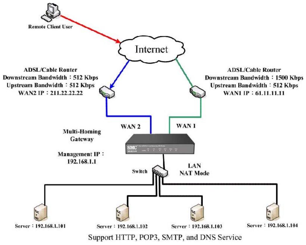
(Figure10-25)
Figure10-25 Complete the Setting of Providing Several Services by Several Virtual Server
Chapter 11 VPN
VPN
The SMC BR21VPN adopts VPN to set up safe and private network service. And combine the remote Authentication system in order to integrate the remote network and PC of the enterprise. Also provide the enterprise and remote users a safe encryption way to have best efficiency and encryption when delivering data. Therefore, it can save lots of problem for manager.
【IPSec Autokey】: The system manager can create a VPN connection using Autokey IKE. Autokey IKE (Internet Key Exchange) provides a standard method to negotiate keys between two security gateways. Also set up IPSec Lifetime and Preshared Key of the SMC BR21VPN.
[PPTP Server]: The System Manager can set up VPN-PPTP Server functions in this chapter.
【PPTP Client】: The System Manager can set up VPN-PPTP Client functions in this chapter

How to use VPN?
To set up a Virtual Private Network (VPN), you need to configure an Access Policy include IPSec Autokey, PPTP Server, or PPTP Client settings of Tunnel to make a VPN connection.
Define the required fields of VPN:
RSA:
A public-key cryptosystem for encryption and authentication.
Preshared Key:
The IKE VPN must be defined with a Preshared Key. The Key may be up to 128 bytes long.
ISAKMP (Internet Security Association Key Management Protocol):
An extensible protocol-encoding scheme that complies to the Internet Key Exchange (IKE) framework for establishment of Security Associations (SAs).
Main Mode:
This is another first phase of the Oakley protocol in establishing a security association, but instead of using three packets like in aggressive mode, it uses six packets.
Aggressive mode:
This is the first phase of the Oakley protocol in establishing a security association using three data packets.
AH (Authentication Header):
One of the IPSec standards that allows for data integrity of data packets.
ESP (Encapsulating Security Payload):
One of the IPSec standards that provides for the confidentiality of data packets.
DES (Data Encryption Standard):
The Data Encryption Standard developed by IBM in 1977 is a 64-bit block encryption block cipher using a 56-bit key.
Triple-DES (3DES):
The DES function performed three times with either two or three cryptographic keys.
AES (Advanced Encryption Standard):
An encryption algorithm yet to be decided that will be used to replace the aging DES encryption algorithm and that the NIST hopes will last for the next 20 to 30 years.
NULL Algorithm:
It is a fast and convenient connecting mode to make sure its privacy and authentication without encryption. NULL Algorithm doesn't provide any other safety services but a way to substitute ESP Encryption
SHA-1 (Secure Hash Algorithm-1):
A message-digest hash algorithm that takes a message less than 264 bits and produces a 160-bit digest.
MD5:
MD5 is a common message digests algorithm that produces a 128-bit message digest from an arbitrary length input, developed by Ron Rivest.
GRE/IPSec:
The device Select GRE/IPSec (Generic Routing Encapsulation) packet seal technology.
To display the VPN connection status via icon
| Chart | -- | ||
| Meaning | Not be applied | Disconnect | Connecting |
Name:
The VPN name to identify the IPSec Autokey definition. The name must be the only one and cannot be repeated.
Gateway IP:
The WAN interface IP address of the remote Gateway.
IPSec Algorithm:
To display the Algorithm way.
Configure:
- Click Modify to change the argument of IPSec; click Remove to remote the setting. (Figure11-1)

Figure11-1 IPSec Autokey WebUI
Define the required fields of PPTP Server Function
PPTP Server:
To select Enable or Disable
Client IP Range:
Setting the IP addresses range for PPTP Client connection
i:
To display the VPN connection status via icon
| Chart | -- | ||
| Meaning | Not be applied | Disconnect | Connecting |
User Name:
- Display the PPTP Client user's name when connecting to PPTP Server.
Client IP:
- Display the PPTP Client's IP address when connecting to PPTP Server.
Uptime:
- Display the connection time between PPTP Server and Client.
Configure:
- Click Modify to modify the PPTP Server Settings or click Remove to remove the setting (Figure11-2)
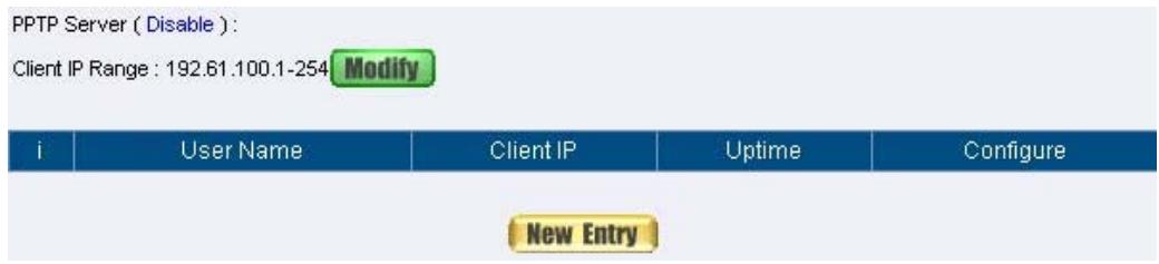
Figure11-2 PPTP Server WebUI
Define the required fields of PPTP Client Function
To display the VPN connection status via icon
| Chart | -- | ||
| Meaning | Not be applied | Disconnect | Connecting |
User Name:
- Displays the PPTP Client user's name when connecting to PPTP Server.
Server IP or Domain Name:
- Display the PPTP Server IP addresses or Domain Name when connecting to PPTP Server.
Encryption:
- Display PPTP Client and PPTP Server transmission, whether opens the encryption authentication mechanism.
Uptime:
- Displays the connection time between PPTP Server and Client.
Configure:
- Click Modify to change the argument of PPTP Client; click Remove to remote the setting. (Figure11-3)
PPTP Client :

Figure11-3 PPTP Client WebUI
Define the required fields of Tunnel Function
To display the VPN connection status via icon
| Chart | -- | ||
| Meaning | Not be applied | Disconnect | Connecting |
Name:
The VPN name to identify the VPN tunnel definition. The name must be the only one and cannot be repeated.
Source Subnet:
- Displays the Source Subnet.
Destination Subnet:
- Displays the Destination Subnet.
IPSec / PPTP:
- Displays the Virtual Private Network's(IPSec Autokey, PPTP Server, PPTP Client) settings of Tunnel function.
Configure:
- Click Modify to change the argument of VPN Tunnel; click Remove to remote the setting.(Figure11-4)

Figure11-4 VPN Tunnel Web UI
We set up two VPN examples in this chapter:
| No. | Suitable Situation | Example | Page |
| Ex1 | IPSec Autokey | Setting IPSec VPN connection between two SMC BR21VPN | 133 |
| Ex2 | PPTP | Setting PPTP VPN connection between two SMC BR21VPN | 146 |
Example
Setting IPSec VPN connection between two SMC BR21VPN
Preparation
Company A WAN IP: 61.11.11.11
LAN IP: 192.168.10.X
Company B WAN IP: 211.22.22.22
LAN IP: 192.168.20.X
This example takes two SMC BR21VPN as work platform. Suppose Company A 192.168.10.100 create a VPN connection with Company B 192.168.20.100 for downloading the sharing file.
The Default Gateway of Company A is the LAN IP of the SMC BR21VPN 192.168.10.1. Follow the steps below:
STEP 1. Enter the default IP of Gateway of Company A's SMC BR21VPN, 192.168.10.1 and select IPSec Autokey in VPN. Click New Entry. (Figure11-5)

Figure11-5 IPSec Autokey WebUI
STEP 2 . In the list of IPSec Autokey, fill in Name with VPN_A. (Figure11-6)
STEP 3 . Select Remote Gateway-Fixed IP or Domain Name In To
Destination list and enter the IP Address.
STEP 4 . Select Preshare in Authentication Method and enter the Preshared Key (max: 100 bits)
STEP 5 . Select ISAKMP Algorithm in Encapsulation list. Choose the Algorithm when setup connection. Please select ENC Algorithm (3DES/DES/AES), AUTH Algorithm (MD5/SHA1), and Group (GROUP1, 2,5). Both sides have to choose the same group. Here we select 3DES for ENC Algorithm, MD5 for AUTH Algorithm, and GROUP1 for group. (Figure11-9)
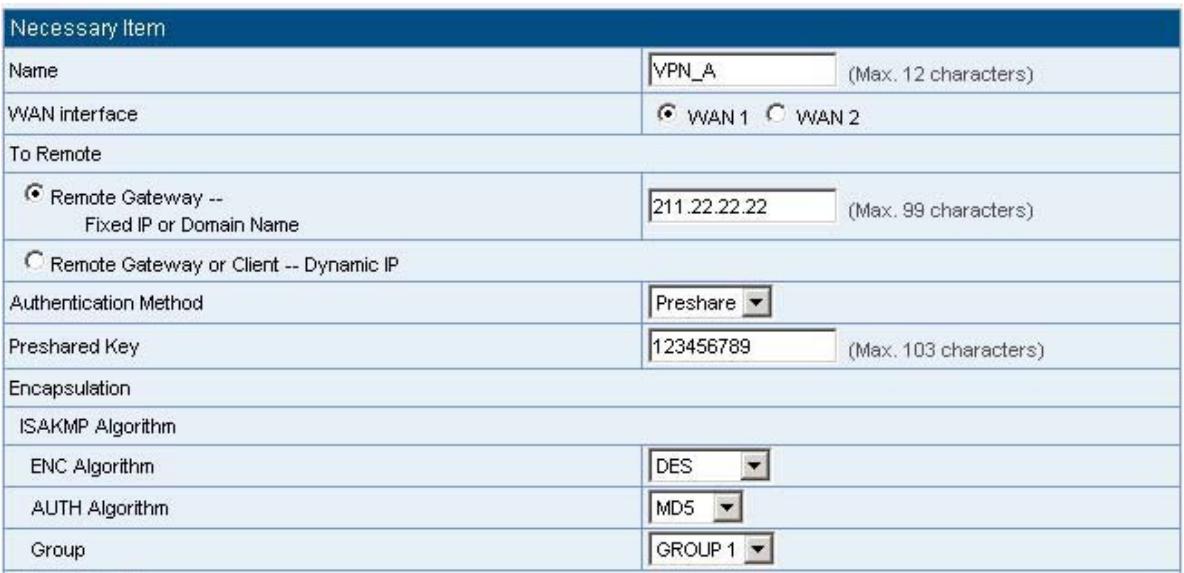
Figure11-9 IPSec Encapsulation Setting
STEP 6 . You can choose Data Encryption + Authentication or Authentication
Only to communicate in IPSec Algorithm list:
ENC Algorithm: 3DES/DES/AES/NULL
AUTH Algorithm: MD5/SHA1
Here we select 3DES for ENC Algorithm and MD5 for AUTH Algorithm to make sure the encapsulation way for data transmission (Figure11-10)

Figure11-10 IPSec Algorithm Setting
STEP 7 . After selecting GROUP1 in Perfect Forward Secrecy, enter 3600 seconds in ISAKMP Lifetime, enter 28800 seconds in IPSec Lifetime, and selecting Main mode in Mode. (Figure11-11)

Figure11-11 IPSec Perfect Forward Secrecy Setting
STEP 8 . Complete the IPSec Autokey setting. (Figure11-12)

Figure11-12 Complete Company A IPSec Autokey Setting
STEP 9 . Enter the following setting in Tunnel of VPN function: (Figure11-13)
Enter a specific Tunnel Name.
From Source: Select LAN
■ From Source Subnet / Mask: Enter 192.168.10.0 / 255.255.255.0.
To Destination: Select To Destination Subnet / Mask.
To Destination Subnet / Mask: Enter 192.168.85.0 / 255.255.255.0.
IPSec / PPTP Setting: Select VPN_A.
Select Show remote Network Neighborhood.
- Click OK. (Figure11-14)
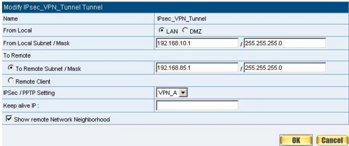
Figure11-13 New Entry Tunnel Setting

Figure11-14 Complete New Entry Tunnel Setting
STEP 10. Enter the following setting in Outgoing Policy: (Figure11-15)
Authentication User: Select All_NET.
Schedule: Select Schedule_1.
QoS: Select QoS_1.
Tunnel: Select IPSec_VPN_Tunnel.
Click OK.(Figure11-16)
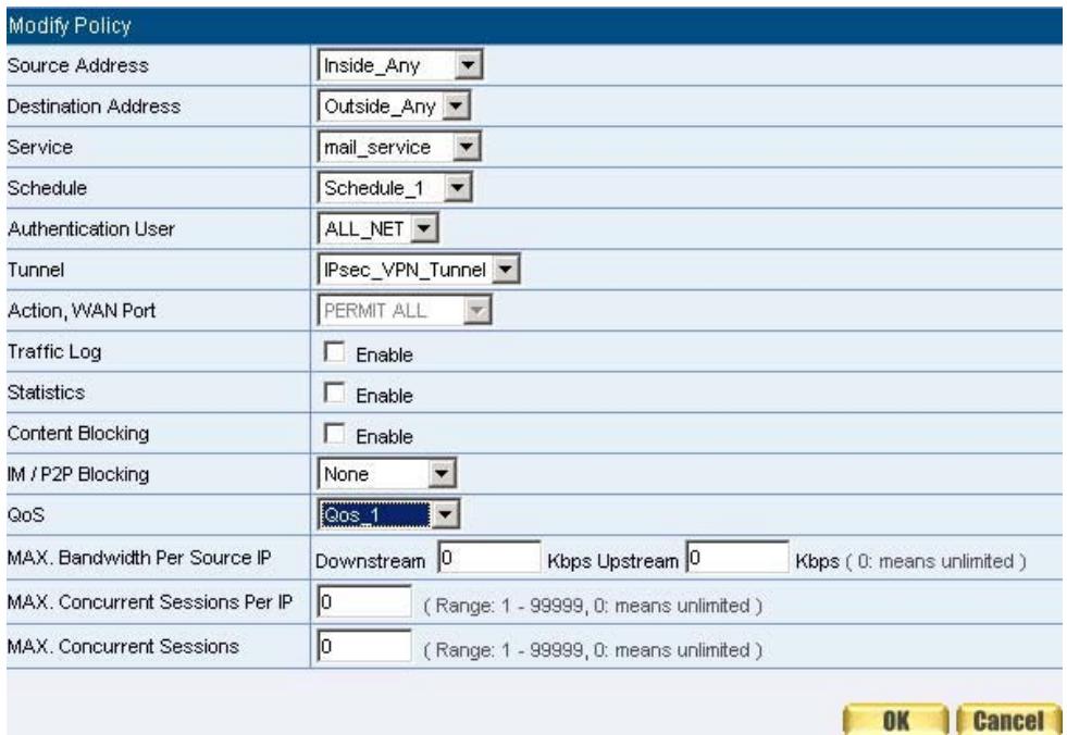
Figure11-15 Setting the VPN Tunnel Outgoing Policy

Figure11-16 Complete the VPN Tunnel Outgoing Policy Setting
STEP 11 . Enter the following setting in Incoming Policy: (Figure11-17)
Schedule: Select Schedule_1.
QoS: Select QoS_1.
Tunnel: Select IPSec_VPN_Tunnel.
- Click OK.(Figure11-18)
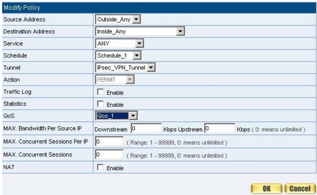
Figure11-17 Setting the VPN Tunnel Incoming Policy

Figure11-18 Complete the VPN Tunnel Incoming Policy Setting
The Default Gateway of Company B is the LAN IP of the SMC BR21VPN 192.168.20.1. Follow the steps below:
STEP 1. Enter the following setting in Multiple Subnet of System Configure function: (Figure11-19)

Figure11-19 Multiple Subnet Setting
STEP 2. Enter the default IP of Gateway of Company B's SMC BR21VPN, 192.168.20.1 and select IPSec Autokey in VPN. Click New Entry. (Figure11-20)

Figure11-20 IPSec Autokey Web UI
STEP 3. In the list of IPSec Autokey, fill in Name with VPN_B.
STEP 4. Select Remote Gateway-Fixed IP or Domain Name In To Destination list and enter the IP Address
STEP 5. Select Preshare in Authentication Method and enter the Preshared Key (max: 100 bits) (Figure11-23)
STEP 6. Select ISAKMP Algorithm in Encapsulation list. Choose the Algorithm when setup connection. Please select ENC Algorithm (3DES/DES/AES), AUTH Algorithm (MD5/SHA1), and Group (GROUP1, 2,5). Both sides have to choose the same group. Here we select 3DES for ENC Algorithm, MD5 for AUTH Algorithm, and GROUP1 for group. (Figure11-24)
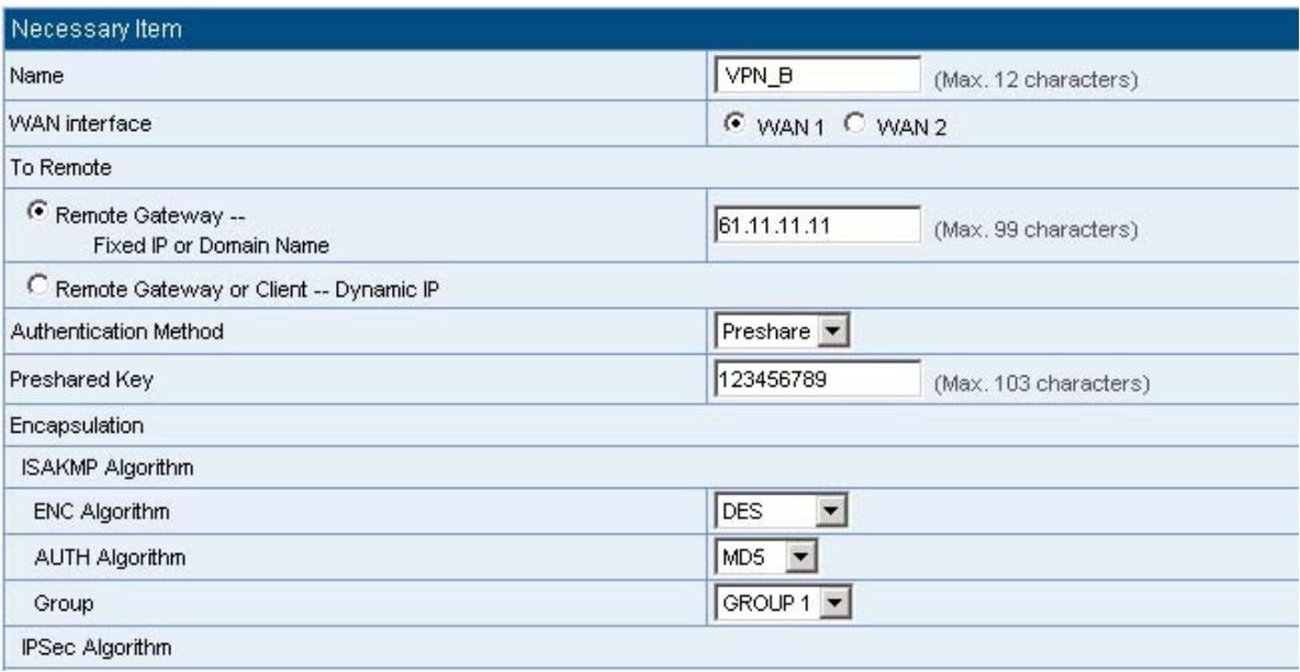
Figure11-24 IPSec Encapsulation Setting
STEP 7. You can choose Data Encryption + Authentication or Authentication
Only to communicate in IPSec Algorithm list:
ENC Algorithm: 3DES/DES/AES/NULL
AUTH Algorithm: MD5/SHA1
Here we select 3DES for ENC Algorithm and MD5 for AUTH Algorithm to make sure the encapsulation way for data transmission. (Figure11-25)

Figure11-25 IPSec Algorithm Setting
STEP 8. After selecting GROUP1 in Perfect Forward Secrecy, enter 3600 seconds in ISAKMP Lifetime, enter 28800 seconds in IPSec Lifetime, and selecting Main mode in Mode. (Figure11-26)

Figure11-26 IPSec Perfect Forward Secrecy Setting
STEP 9.Complete the IPSec Autokey setting. (Figure11-27)

Figure11-27 Complete Company B IPSec Autokey Setting
STEP 10. Enter the following setting in Tunnel of VPN function: (Figure11-28)
Enter a specific Tunnel Name.
From Source: Select LAN
■ From Source Subnet / Mask: Enter 192.168.20.0 / 255.255.255.0.
To Destination: Select To Destination Subnet / Mask.
To Destination Subnet / Mask: Enter 192.168.10.0 / 255.255.255.0.
IPSec / PPTP Setting: Select VPN_B.
Select Show remote Network Neighborhood.
- Click OK. (Figure11-29)
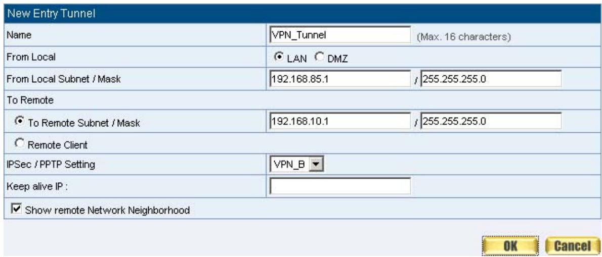
Figure11-28 New Entry Tunnel Setting

Figure11-29 Complete New Entry Tunnel Setting
STEP 11. Enter the following setting in Outgoing Policy: (Figure11-30)
Authentication User: Select All_NET.
Schedule: Select Schedule_1.
QoS: Select QoS_1.
Tunnel: Select VPN_Tunnel.
Click OK.(Figure11-31)
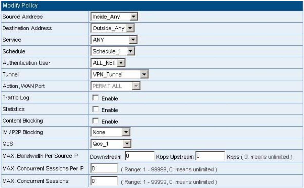


Figure11-30 Setting the VPN Tunnel Outgoing Policy
Figure11-31 Complete the VPN Tunnel Outgoing Policy Setting
STEP 12. Enter the following setting in Incoming Policy: (Figure11-32)
Schedule: Select Schedule_1.
QoS: Select QoS_1.
Tunnel: Select IPSec_VPN_Tunnel.
- Click OK.(Figure11-33)
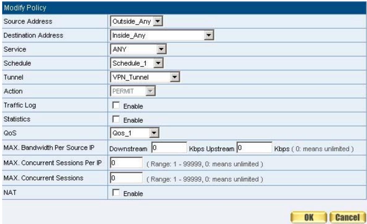
Figure11-32 Setting the VPN Tunnel Incoming Policy

Figure11-33 Complete the VPN Tunnel Incoming Policy Setting
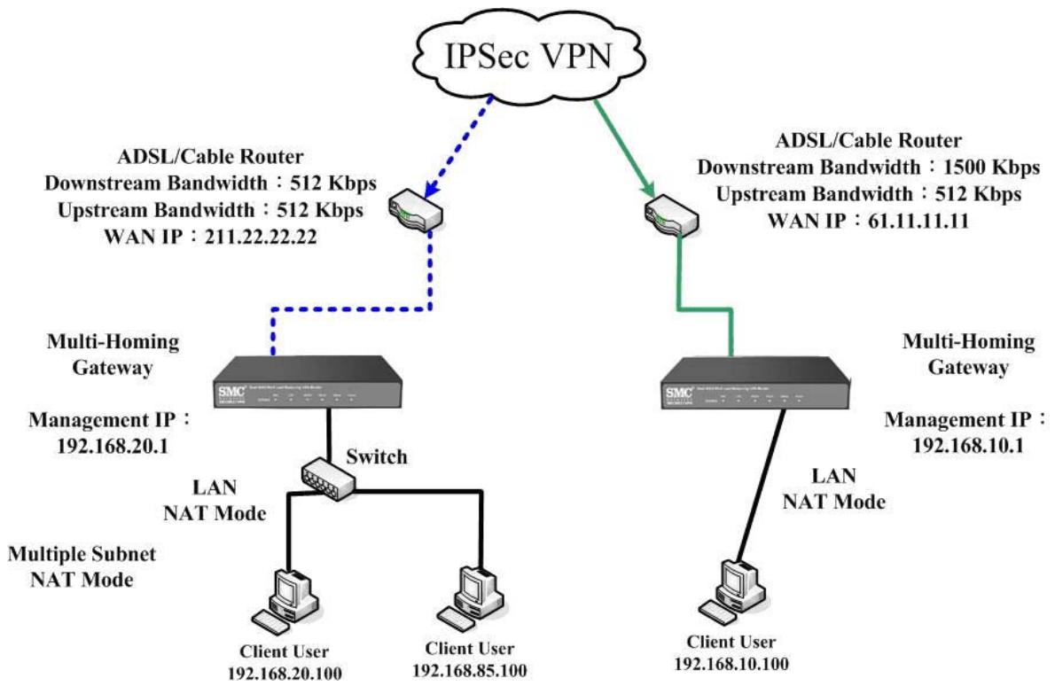
Figure 11-34 IPSec VPN Connection Deployment
Preparation
Company A WAN IP: 61.11.11.11
LAN IP: 192.168.10.X
Company B WAN IP: 211.22.22.22
LAN IP: 192.168.20.X
This example takes two SMC BR21VPN as flattop. Suppose Company B 192.168.20.100 is going to have VPN connection with Company A 192.168.10.100 and download the resource.
The Default Gateway of Company A is the LAN IP of the SMC BR21VPN 192.168.10.1. Follow the steps below:
STEP 1. Enter PPTP Server of VPN function in the SMC BR21VPN of Company A. Select Modify and enable PPTP Server:
Select Encryption.
Client IP Range: Enter 192.44.75.1-254.
Idle Time: Enter 0. (Figure11-35)

Figure11-35 Enable PPTP VPN Server Settings

Idle Time: the setting time that the VPN Connection will auto disconnect under
unused situation. (Unit: minute)
STEP 2.Add the following settings in PPTP Server of VPN function in the SMC BR21VPN of Company A:
Select New Entry. (Figure11-36)
■ User Name: Enter PPTP_Connection.
■ Password: Enter 123456789.
Client IP assigned by: Select IP Range.
- Click OK. (Figure11-37)
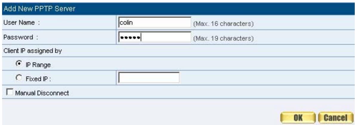
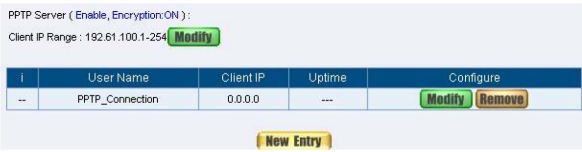
Figure 11-36 PPTP VPN Server Setting
Figure 11-37 Complete PPTP VPN Server Setting
STEP 3. Enter the following setting in Tunnel of VPN function: (Figure11-38)
Enter a specific Tunnel Name.
From Source: Select LAN
■ From Source Subnet / Mask: Enter 192.168.10.0 / 255.255.255.0.
To Destination: Select To Destination Subnet / Mask.
To Destination Subnet / Mask: Enter 192.168.20.0 / 255.255.255.0.
IPSec / PPTP Setting: Select PPTP Servers_PPTP_Connection.
Select Show remote Network Neighborhood.
- Click OK. (Figure11-39)
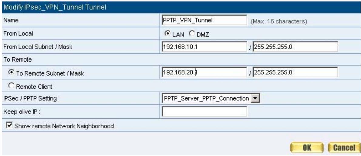

Figure11-38 New Entry Tunnel Setting
Figure11-39 Complete New Entry Tunnel Setting
STEP 4. Enter the following setting in Outgoing Policy: (Figure11-40)
Authentication User: Select All_NET.
Schedule: Select Schedule_1.
QoS: Select QoS_1.
Tunnel: Select PPTP_VPN_Tunnel.
- Click OK.(Figure11-41)
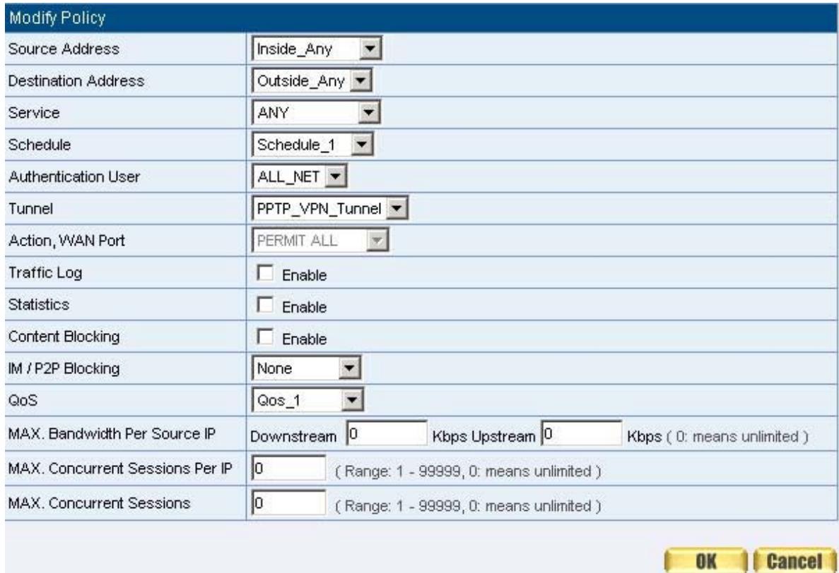

Figure11-40 Setting the VPN Tunnel Outgoing Policy
Figure11-41 Complete the VPN Tunnel Outgoing Policy Setting
STEP 5. Enter the following setting in Incoming Policy: (Figure11-42)
Schedule: Select Schedule_1.
QoS: Select QoS_1.
Tunnel: Select PPTP_VPN_Tunnel.
Click OK.(Figure11-43)
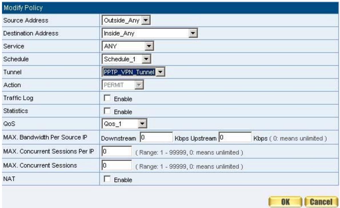
Figure11-42 Setting the VPN Tunnel Incoming Policy

Figure11-43 Complete the VPN Tunnel Incoming Policy Setting
The Default Gateway of Company B is the LAN IP of the SMC BR21VPN 192.168.20.1. Follow the steps below:
STEP 1.Add the following settings in PPTP Client of VPN function in the SMC BR21VPN of Company B:
- Click New Entry Button. (Figure11-44)
■ User Name: Enter PPTP_Connection.
■ Password: Enter123456789.
Server IP or Domain Name: Enter 61.11.11.11.
Select Encryption. - Click OK. (Figure11-45)
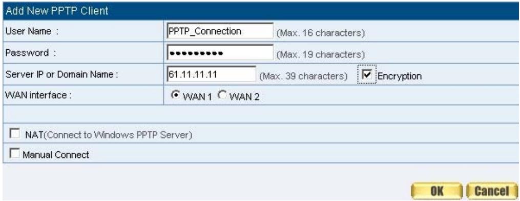
Figure 11-44 PPTP VPN Client Setting

Figure 11-45 Complete PPTP VPN Client Setting
STEP 2. Enter the following setting in Tunnel of VPN function: (Figure11-46)
Enter a specific Tunnel Name.
From Source: Select LAN
■ From Source Subnet / Mask: Enter 192.168.20.0 / 255.255.255.0.
To Destination: Select To Destination Subnet / Mask.
To Destination Subnet / Mask: Enter 192.168.10.0 / 255.255.255.0.
IPSec / PPTP Setting: Select PPTP客户的 PPTP_Connection.
Select Show remote Network Neighborhood.
Click OK. (Figure11-47)
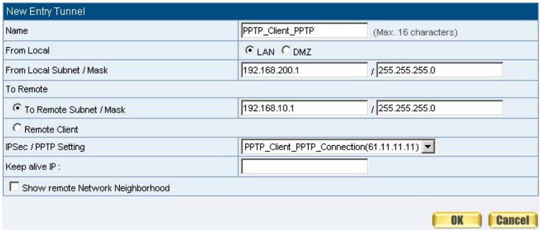

Figure11-46 New Entry Tunnel Setting
Figure11-47 Complete New Entry Tunnel Setting
STEP 3. Enter the following setting in Outgoing Policy: (Figure11-48)
Authentication User: Select All_NET.
Schedule: Select Schedule_1.
QoS: Select QoS_1.
Tunnel: Select PPTP_VPN_Tunnel.
Click OK.(Figure11-49)
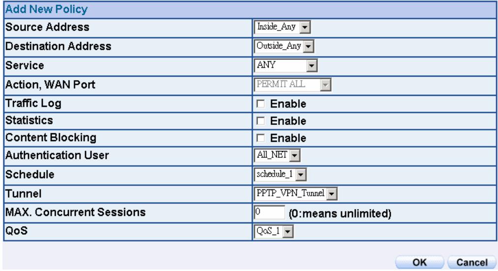
Figure11-48 Setting the VPN Tunnel Outgoing Policy

Figure11-49 Complete the VPN Tunnel Outgoing Policy Setting
STEP 4. Enter the following setting in Incoming Policy: (Figure11-50)
Schedule: Select Schedule_1.
QoS: Select QoS_1.
Tunnel: Select PPTP客户的 PPTP.
Click OK.(Figure11-51)
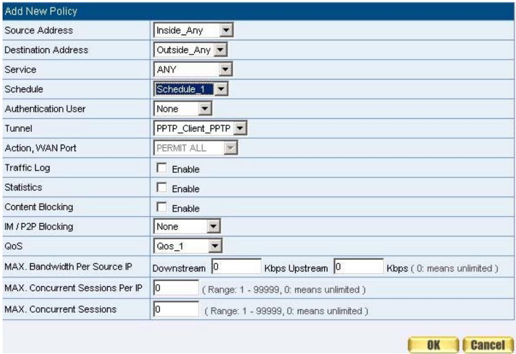
Figure11-50 Setting the VPN Tunnel Incoming Policy

Figure11-51 Complete the VPN Tunnel Incoming Policy Setting
STEP 5.Complete PPTP VPN Connection. (Figure11-52)
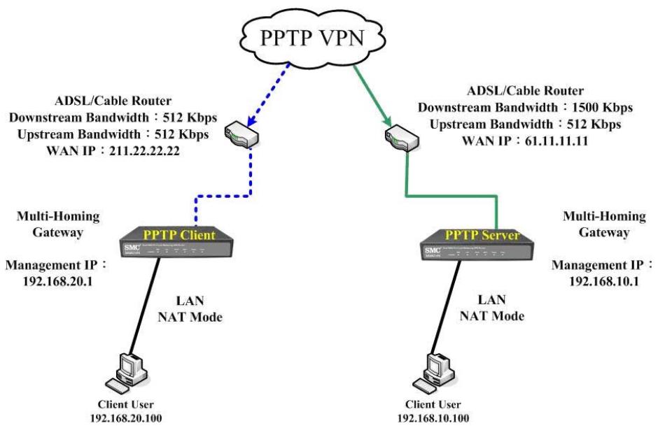
Figure 11-52 PPTP VPN Connection Deployment
Chapter 12 Policy
Policy
Every packet has to be detected if it corresponds with Policy or not when it passes the SMC BR21VPN. When the conditions correspond with certain policy, it will pass the SMC BR21VPN by the setting of Policy without being detected by other policy. But if the packet cannot correspond with any Policy, the packet will be intercepted.
The parameter of the policy includes Source Address, Destination Address, Service, Action, WAN Port, Traffic Log, Statistics, Content Blocking, Anti-Virus, Authentication User, Schedule, Alarm Threshold, Trunk, Max. Concurrent Sessions, and QoS. Control policies decide whether packets from different network objects, network services, and applications are able to pass through the SMC BR21VPN.

How to use Policy?
The device uses policies to filter packets. The policy settings are: source address, destination address, services, permission, packet log, packet statistics, and flow alarm. Based on its source addresses, a packet can be categorized into:
(1) Outgoing: The source IP is in LAN network; the destination is in WAN network. The system manager can set all the policy rules of Outgoing packets in this function
(2) Incoming: The source IP is in WAN network; the destination is in LAN network. (For example: Mapped IP, Virtual Server) The system manager can set all the policy rules of Incoming packets in this function
(3) WAN to DMZ: The source IP is in WAN network; the destination is in DMZ network. (For example: Mapped IP, Virtual Server) The system manager can set all the policy rules of WAN to DMZ packets in this function
(4) LAN to DMZ: The source IP is in LAN network; the destination is in DMZ network. The system manager can set all the policy rules of LAN to DMZ packets in this function
(5) DMZ to LAN: The source IP is in DMZ network; the destination is in LAN network. The system manager can set all the policy rules of DMZ to LAN packets in this function
(6) DMZ to WAN: The source IP is in DMZ network; the destination is in WAN network. The system manager can set all the policy rules of DMZ to WAN packets in this function

All the packets that go through SMC BR21VPN must pass the policy permission
(except VPN). Therefore, the LAN, WAN, and DMZ network have to set the applicable policy when establish network connection.
Define the required fields of Policy
Source and Destination:
Source IP and Destination IP is according to the SMC BR21VPN's point of view. The active side is the source; passive side is destination.
Service:
It is the service item that controlled by Policy. The user can choose default value or the custom services that the system manager set in Service function.
Action, WAN Port:
Control actions to permit or reject packets that delivered between LAN network and WAN network when pass through SMC BR21VPN (See the chart and illustration below)
| Chart | Name | Illustration |
| ✓ | Permit all WAN network Interface | Allow the packets that correspond with policy to be transferred by WAN1/2 Port |
| 1 | Permit WAN1 | Allow the packets that correspond with policy to be transferred by WAN1 Port |
| 2 | Permit WAN2 | Allow the packets that correspond with policy to be transferred by WAN2 Port |
| × | DENY | Reject the packets that correspond with policy to be transferred by WAN Port |
Option:
To display if every function of Policy is enabled or not. If the function is enabled and then the chart of the function will appear (See the chart and illustration below)
| Chart | Name | Illustration |
| Traffic Log | Enable traffic log | |
| Statistics | Enable traffic statistics | |
| Authentication User | Enable Authentication User | |
| Schedule | Enable the policy to automatically execute the function in a certain time | |
| Content Blocking | Enable Content Blocking | |
| QoS | Enable QoS |
Traffic Log:
Record all the packets that go through policy.
Statistics:
Chart of the traffic that go through policy
Content Blocking:
To restrict the packets that passes through the policy
Authentication-User:
The user have to pass the authentication to connect by Policy
Schedule:
Setting the policy to automatically execute the function in a certain time
MAX. Concurrent Sessions:
Set the concurrent sessions that permitted by policy. And if the sessions exceed the setting value, the surplus connection cannot be set successfully.
QoS:
Setting the Guarantee Bandwidth and Maximum Bandwidth of the Policy (the bandwidth is shared by the users who correspond to the Policy)
Move:
Every packet that passes the SMC BR21VPN is detected from the front policy to the last one. So it can modify the priority of the policy from the selection.
| No. | Suitable Situation | Example | Page |
| Ex1 | Outgoing | Set up the policy that can monitor the internal users. (Take Logging, Statistics, Alarm Threshold for example) | 163 |
| Ex2 | Outgoing | Forbid the users to access to specific network. (Take specific WAN IP and Content Blocking for example) | 166 |
| Ex3 | Outgoing | Only allow the users who pass Authentication to access to Internet in particular time. | 171 |
| Ex4 | Incoming | The external user control the internal PC through remote control software (Take pcAnywhere for example) | 173 |
| Ex5 | WAN to DMZ | Under DMZ NAT Mode, set a FTP Server and restrict the download bandwidth from external and MAX. Concurrent Sessions. | 175 |
| Ex6 | WAN to DMZ DMZ to WAN LAN to DMZ | Set a Mail Server to allow the internal and external users to receive and send e-mail under DMZ Transparent Mode | 177 |
Example
Set up the policy that can monitor the internal users. (Take Logging, Statistics, and Alarm Threshold for example)
STEP 1. Enter the following setting in Outgoing Policy:
- Click New Entry
Select Logging
Select Statistics - Click OK (Figure12-1)
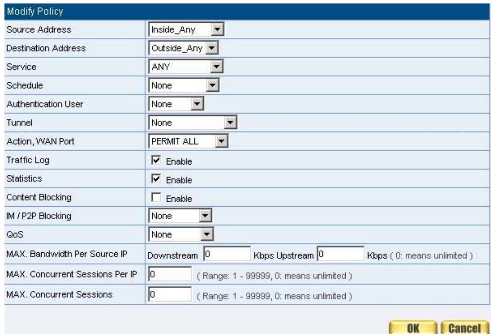
Figure12-1 Setting the different Policies
STEP 2 . Complete the setting of Logging, Statistics, and Alarm Threshold in Outgoing Policy: (Figure12-2)

Figure12-2 Complete Policy Setting
STEP 3. Obtain the information in Traffic of Log function if you want to monitor all the packets of the SMC BR21VPN. (Figure12-3)
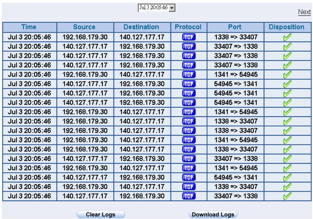
Figure12-3 Traffic Log Monitor WebUI
STEP 4. To display the traffic record that through Policy to access to Internet in Policy Statistics of Statistics function. (Figure12-4)
Bits/Sec Bytes/Sec Total Inside_Any to Outside_Any Service: ANY Action: PERMIT
Minute Hour Day Week Month Year
Real-time: Down 3.4 MBits/sec Up 63.0 KBits/sec
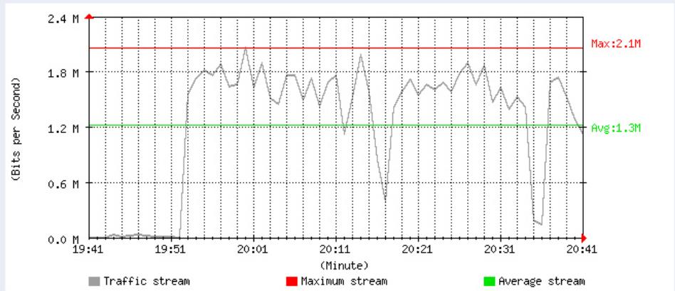
Downstream
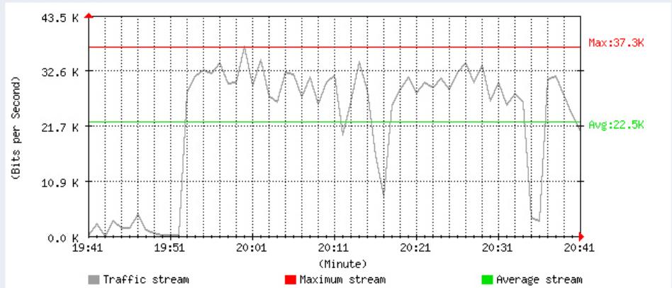
Upstream
Figure12-4 Statistics WebUI
Forbid the users to access to specific network. (Take specific WAN IP and Content Blocking for example)
STEP 1. Enter the following setting in URL Blocking, Script Blocking, P2P Blocking, IM Blocking, and Download Blocking in Content Blocking function: (Figure12-5, 12-6, 12-7, 12-8, 12-9)

Figure12-5 URL Blocking Setting

Figure12-6 Script Blocking Setting
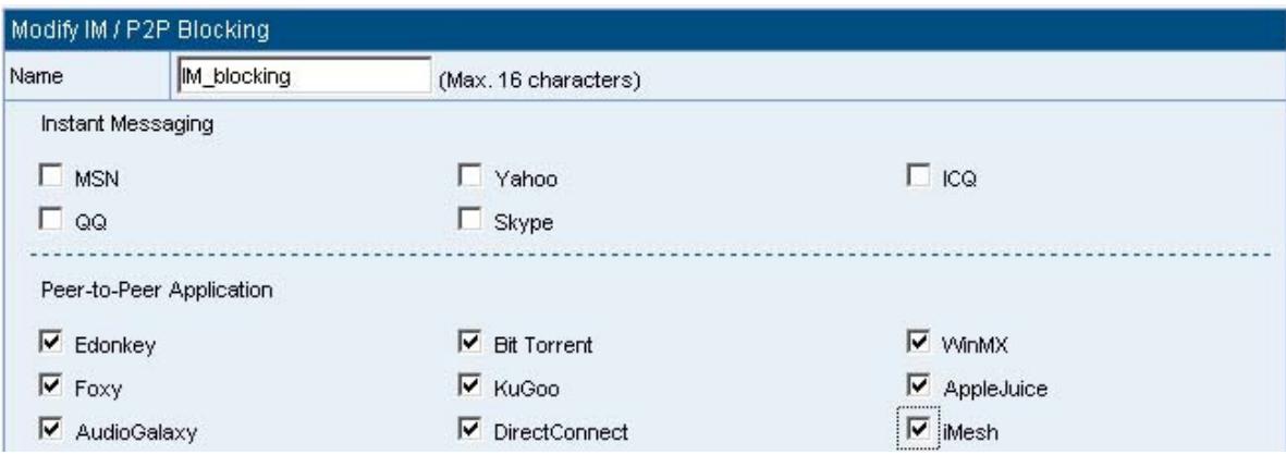
Figure12-7 P2P / IM Blocking Setting
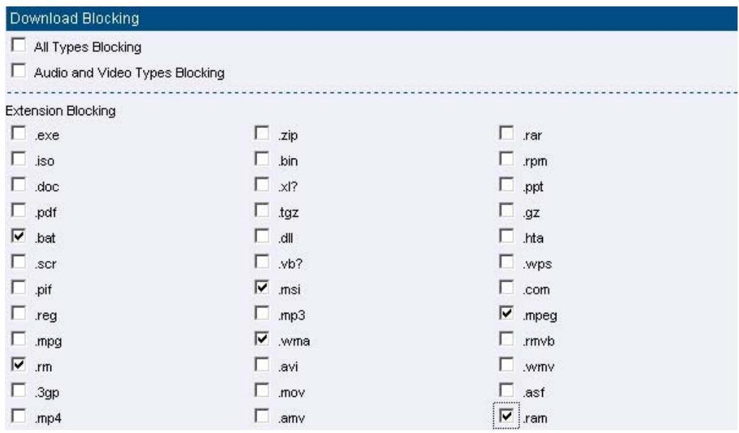
Figure12-8 IM Blocking Setting
Figure12-9 Download Blocking Setting

- URL Blocking can restrict the Internal Users only can access to some specific Website.
- Script Blocking can restrict the Internal Users to access to Script file of Website. (Java, Cookies...etc.)
- P2P Blocking can restrict the Internal Users to access to the file on Internet by P2P. (eDonkey, BT)
- IM Blocking can restrict the Internal Users to send message, files, audio, and video by instant messaging. (Ex: MSN Messenger, Yahoo Messenger, QQ, ICQ and Skype)
- Download Blocking can restrict the Internal Users to access to video, audio, and some specific sub-name file by http protocol directly.
STEP 2. Enter as following in WAN and WAN Group of Address function: (Figure12-10, 12-11)
Figure12-10 Setting the WAN IP that going to block
| Name | IP / Netmask | Configure |
| Outside_Any | 0.0.0.0/0.0.0.0 | In Use |
| Remote_server1 | 61.219.38.39/255.255.255.255 | Modify Remove |
| Remote_server2 | 202.1.237.21/255.255.255.255 | Modify Remove |
Figure12-11 WAN Address Group
| Name | Member | Configure |
| Remote_Group | Remote_server1, Remote_server2 | Modify Remove Pause |
The Administrator can group the custom address in Address. It is more convenient when setting policy rule.
STEP 3. Enter the following setting in Outgoing Policy:
- Click New Entry
Destination Address: Select Remote_Group that set by
STEP 2. (Blocking by IP)
■ Action, WAN Port: Select Deny - Click OK (Figure12-12)
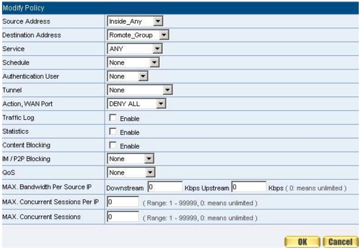
Figure12-12 Setting Blocking Policy
STEP 4 . Enter the following setting in Outgoing Policy:
- Click New Entry
Select Content Blocking & IM / P2P Blocking - Click OK (Figure12-13)
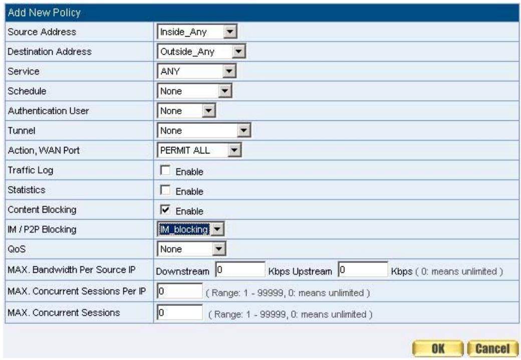
Figure12-13 Setting Content Blocking Policy
STEP 5. Complete the setting of forbidding the users to access to specific network. (Figure12-14)

Figure12-14 Complete Policy Setting

Deny in Policy can block the packets that correspond to the policy rule. The
System Administrator can put the policy rule in the front to prevent the user connecting with specific IP.
Only allow the users who pass Authentication to access to Internet in particular time
STEP 1. Enter the following in Schedule function: (Figure12-15)

Figure12-15 Add New Schedule
STEP 2. Enter the following in Auth User and Auth User Group in Authentication function: (Figure12-16)

Figure12-16 Setting Auth User Group

The Administrator can use group function the Authentication and Service. It is more convenient when setting policy.
STEP 3. Enter the following setting in Outgoing Policy:
- Click New Entry
Authentication User: Select laboratory
Schedule: Select WorkingTime - Click OK (Figure12-17)
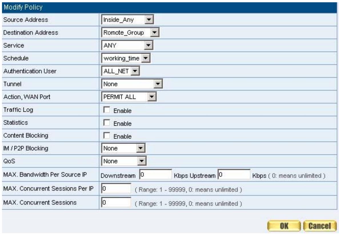
Figure12-17 Setting a Policy of Authentication and Schedule
STEP 4. Complete the policy rule of only allows the users who pass authentication to access to Internet in particular time. (Figure12-18)

Figure12-18 Complete Policy Setting
The external user control the internal PC through remote control software (Take pcAnywhere for example)
STEP 1 . Set up a Internal PC controlled by external user, and Internal PC's IP Address is 192.168.1.2
STEP 2. Enter the following setting in Virtual Server1 of Virtual Server function: (Figure12-19)
Virtual Server Real IP 61.11.11.11

Figure12-19 Setting Virtual Server
STEP 3. Enter the following in Incoming Policy:
- Click New Entry
Destination Address: Select Virtual Server1 (61.11.11.12)
Service: Select PC-Anywhere (5631-5632) - Click OK (Figure12-20)
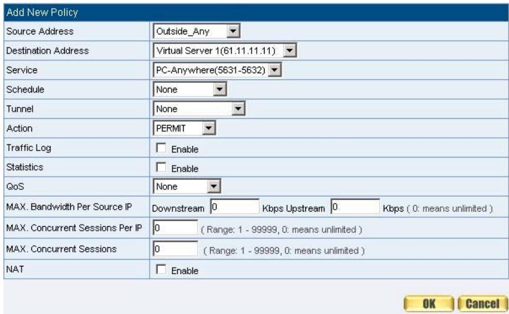
Figure12-20 Setting the External User Control the Internal PC Policy
STEP 4 . Complete the policy for the external user to control the internal PC through remote control software. (Figure12-21)

Figure12-21 Complete Policy Setting
Set a FTP Server under DMZ NAT Mode and restrict the download bandwidth from external and MAX. Concurrent Sessions.
STEP 1 . Set a FTP Server under DMZ, which IP is 192.168.3.2 (The DMZ Interface Address is192.168.3.1/24)
STEP 2. Enter the following setting in Virtual Server1 of Virtual Server function: (Figure12-22)
Virtual Server Real IP 61.11.11.12

Figure12-22 Setting up Virtual Server Corresponds to FTP Server

When using the function of Incoming or WAN to DMZ in Policy, strong suggests
that cannot select ANY in Service. It may being attacked by Hacker easily.
STEP 3. Enter the following in QoS: (Figure12-23)
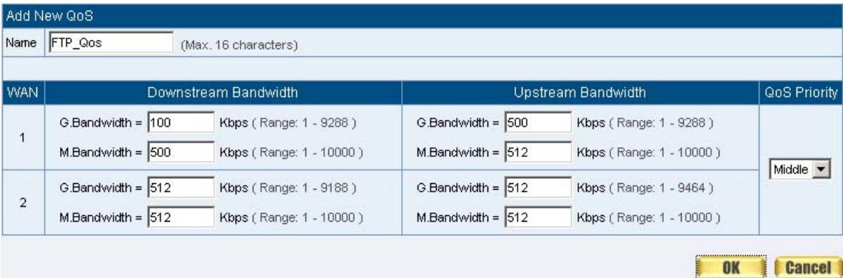
Figure12-23 QoS Setting
STEP 4 . Enter the following in WAN to DMZ Policy:
- Click New Entry
Destination Address: Select Virtual Server1 (61.11.11.12)
Service: Select FTP (21)
QoS: Select FTP_QoS
MAX. Concurrent Sessions: Enter 100 - Click OK (Figure12-24)
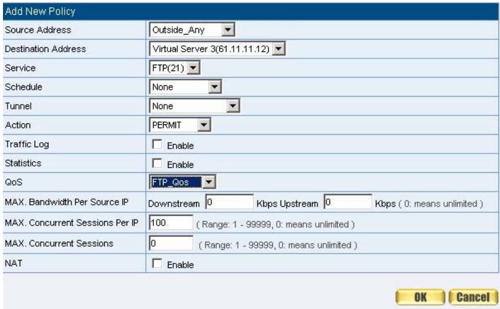
Figure12-24 Add New Policy
STEP 5. Complete the policy of restricting the external users to access to internal network server (which may occupy the resource of network) (Figure12-25)

Figure12-25 Complete the Policy Setting
Set a Mail Server to allow the internal and external users to receive and send e-mail under DMZ Transparent Mode
STEP 1 . Set a Mail Server in DMZ and set its network card's IP Address as 61.11.11.12. The DNS setting is external DNS Server.
STEP 2 . Add the following setting in DMZ of Address function: (Figure12-26)
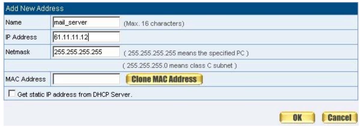
Figure12-26 the Mail Server's IP Address Corresponds to Name Setting in Address Book of Mail Server
STEP 3 . Add the following setting in Group of Service function: (Figure12-27)

Figure12-27 Setting up a Service Group that has POP3, SMTP, and DNS
STEP 4 . Enter the following setting in WAN to DMZ Policy:
- Click New Entry
Destination Address: Select Mail Servers
Service: Select E-mail - Click OK (Figure12-28)
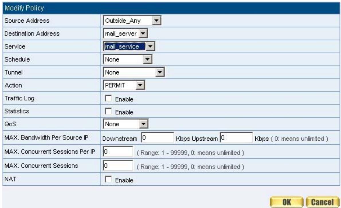
Figure12-28 Setting a Policy to access Mail Service by WAN to DMZ
STEP 5 . Complete the policy to access mail service by WAN to DMZ. (Figure12-29)

Figure12-29 Complete the Policy to access Mail Service by WAN to DMZ
STEP 6 . Add the following setting in LAN to DMZ Policy:
- Click New Entry
Destination Address: Select Mail Servers
Service: Select E-mail - Click OK (Figure12-30)
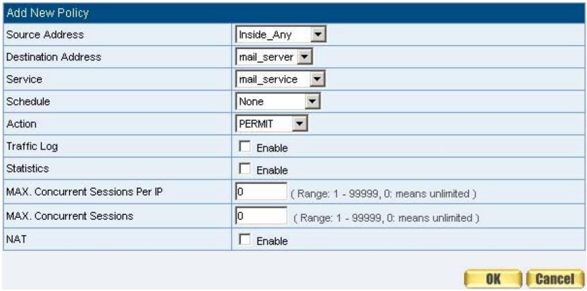
Figure12-30 Setting a Policy to access Mail Service by LAN to DMZ
STEP 7. Complete the policy to access mail service by LAN to DMZ (Figure12-31)

Figure12-31 Complete the Policy to access Mail Service by LAN to DMZ
STEP 8 . Add the following setting in DMZ to WAN Policy:
- Click New Entry
Source Address: Select Mail Servers
Service: Select E-mail - Click OK (Figure12-32)
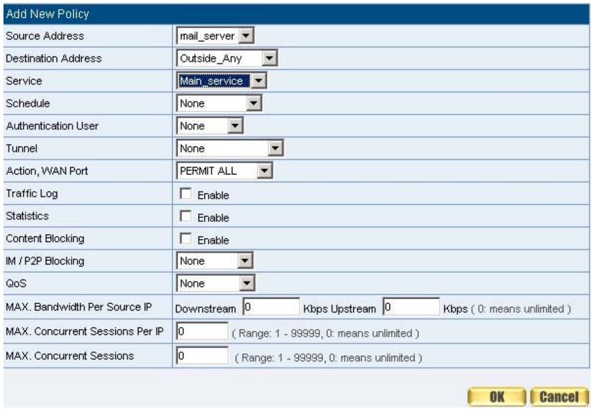
Figure12-32 Setting the Policy of Mail Service by DMZ to WAN
STEP 9. Complete the policy access to mail service by DMZ to WAN. (Figure12-33)

Figure12-33 Complete the Policy access to Mail Service by DMZ to WAN
Chapter 13 Alert Setting
Alert Setting
When the SMC BR21VPN had detected attacks from hackers and the internal PC sending large DDoS attacks. The Internal Alert and External Alert will start on blocking these packets to maintain the whole network.
In this chapter, we will have the detailed illustration about Internal Alert and External Alert:
Detect SYN Attack:
- Select this option to detect TCP SYN attacks that hackers send to server computers continuously to block or cut down all the connections of the servers. These attacks will cause valid users cannot connect to the servers.
【SYN Flood Threshold(Total) Pkts/Sec】: The system Administrator can enter the maximum number of SYN packets per second that is allowed to enter the network/SMC BR21VPN. If the value exceeds the setting one, and then the device will determine it as an attack.
【SYN Flood Threshold(Per Source IP) Pkts/Sec】: The system Administrator can enter the maximum number of SYN packets per second from attacking source IP Address that is allowed to enter the network/SMC BR21VPN. And if value exceeds the setting one, and then the device will determine it as an attack.
【SYN Flood Threshold Blocking Time(Per Source IP) Seconds】: When the SMC BR21VPN determines as being attacked, it will block the attacking source IP address in the blocking time you set. After blocking for certain seconds, the device will start to calculate the max number of SYN packets from attacking source IP Address. And if the max number still exceed the define value, it will block the attacking IP Address continuously.
Detect ICMP Attack:
- When Hackers continuously send PING packets to all the machines of the LAN networks or to the SMC BR21VPN via broadcasting, your network is experiencing an ICMP flood attack.
【ICMP Flood Threshold(Total)Pkts/Sec】: The System
Administrator can enter the maximum number of ICMP packets per second that is allowed to enter the network/SMC BR21VPN. If the value exceeds the setting one, and then the device will determine it as an attack.
【ICMP Flood Threshold(Per Source IP)Pkts/Sec】: The System Administrator can enter the maximum number of ICMP packets per second from attacking source IP Address that is allowed to enter the network / SMC BR21VPN. If the value exceeds the setting one, and then the device will determine it as an attack.
【ICMP Flood Threshold Blocking Time(Per Source IP)Seconds]: When the SMC BR21VPN determines as being attacked, it will block the attacking source IP address in the blocking time you set. After blocking for certain seconds, the device will start to calculate the max number of ICMP packets from attacking source IP Address. And if the max number still exceeds the define value, it will block the attacking IP Address continuously.
Detect UDP Attack:
When Hackers continuously send PING packets to all the machines of the LAN networks or to the SMC BR21VPN via broadcasting, your network is experiencing an UDP attack.
【UDP Flood Threshold(Total)Pkts/Sec】: The System Administrator can enter the maximum number of UDP packets per second that is allowed to enter the network/SMC BR21VPN. If the value exceeds the setting one, and then the device will determine it as an attack.
【UDP Flood Threshold(Per Source IP)Pkts/Sec】: The System Administrator can enter the maximum number of UDP packets per second from attacking source IP Address that is allowed to enter the network/SMC BR21VPN. If the value exceeds the setting one, and then the device will determine it as an attack.
【UDP Flood Threshold Blocking Time (Per Source IP) Seconds】: When SMC BR21VPN determines as being attacked, it will block the attacking source IP in the blocking time you set. After blocking for certain seconds, the device will start to calculate the max number of UPD packets from attacking source IP. If the max number still exceeds the define value, it will block the attacking IP Address continuously.
Detect Ping of Death Attack:
- Select this option to detect the attacks of tremendous trash data in PING packets that hackers send to cause System malfunction. This attack can cause network speed to slow down, or even make it necessary to restart the computer to get a normal operation.
Detect IP Spoofing Attack:
■ Select this option to detect spoof attacks. Hackers disguise themselves as trusted users of the network in Spoof attacks. They use a fake identity to try to pass through the SMC BR21VPN System and invade the network.
Detect Port Scan Attack:
- Select this option to detect the port scans hackers use to continuously scan networks on the Internet to detect computers and vulnerable ports that are opened by those computers.
Detect Tear Drop Attack:
- Select this option to detect tear drop attacks. These are packets that are segmented to small packets with negative length. Some Systems treat the negative value as a very large number, and copy enormous data into the System to cause System damage, such as a shut down or a restart.
Filter IP Route Option:
Each IP packet can carry an optional field that specifies the replying address that can be different from the source address specified in packet's header. Hackers can use this address field on disguised packets to invade LAN networks and send LAN networks' data back to them.
Detect Land Attack:
Some Systems may shut down when receiving packets with the same source and destination addresses, the same source port and destination port, and when SYN on the TCP header is marked. Enable this function to detect such abnormal packets.

After System Manager enable External Alert, if the SMC BR21VPN has detected any abnormal situation, the alarm message will appear in External Alarm in Attack Alarm. And if the system manager starts the E-mail Alert Notification in Settings, the device will send e-mail to alarm the system manager automatically.
Internet Alert
SMC BR21VPN Alarm and to prevent the computer which being attacked to send DDoS packets to LAN network
STEP 1 . Select Anomaly Flow IP in Setting and enter the following settings:
Enter The threshold sessions of infected Blaster (per Source IP) (the default value is 30 Sessions/Sec)
- Select Enable Blaster Blocking and enter the Blocking Time (the default time is 60 seconds)
Select Enable E-Mail Alert Notification
Select Enable NetBIOS Alert Notification
IP Address of Administrator: Enter 192.168.1.10
Click OK
Internal Alert Setting is completed. (Figure16-1)
Virus-infected IP Setting
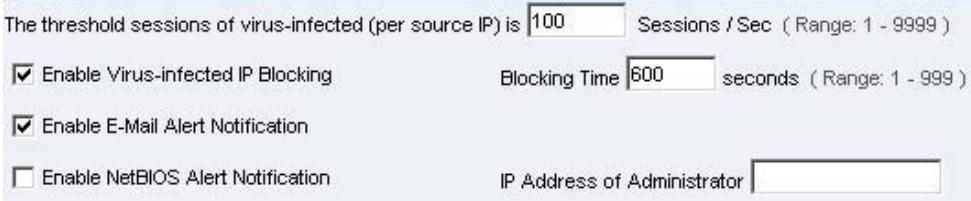
Figure16-1 Internal Alert Settings
After complete the Internal Alert Settings, if the device had detected the internal computer sending large DDoS attack packets and then the alarm message will appear in the Internal Alarm in Attack Alarm or send NetBIOS Alert notification to the infected PC Administrator's PC (Figure16-2, 16-3, 16-4)
If the Administrator starts the E-Mail Alert Notification in Setting, the SMC BR21VPN will send e-mail to Administrator automatically. (Figure16-5)
| Interface | Virus infected IP | Alarm Time |
| LAN | 192.168.1.2 | 2004-11-15 12:03:41 |

Figure16-2 Internal Alert Record
Figure16-3 NetBIOS Alert Notification to the Infected PC
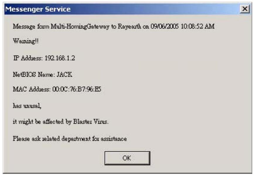
Figure16-4 NetBIOS Alert Notification to Administrator's PC
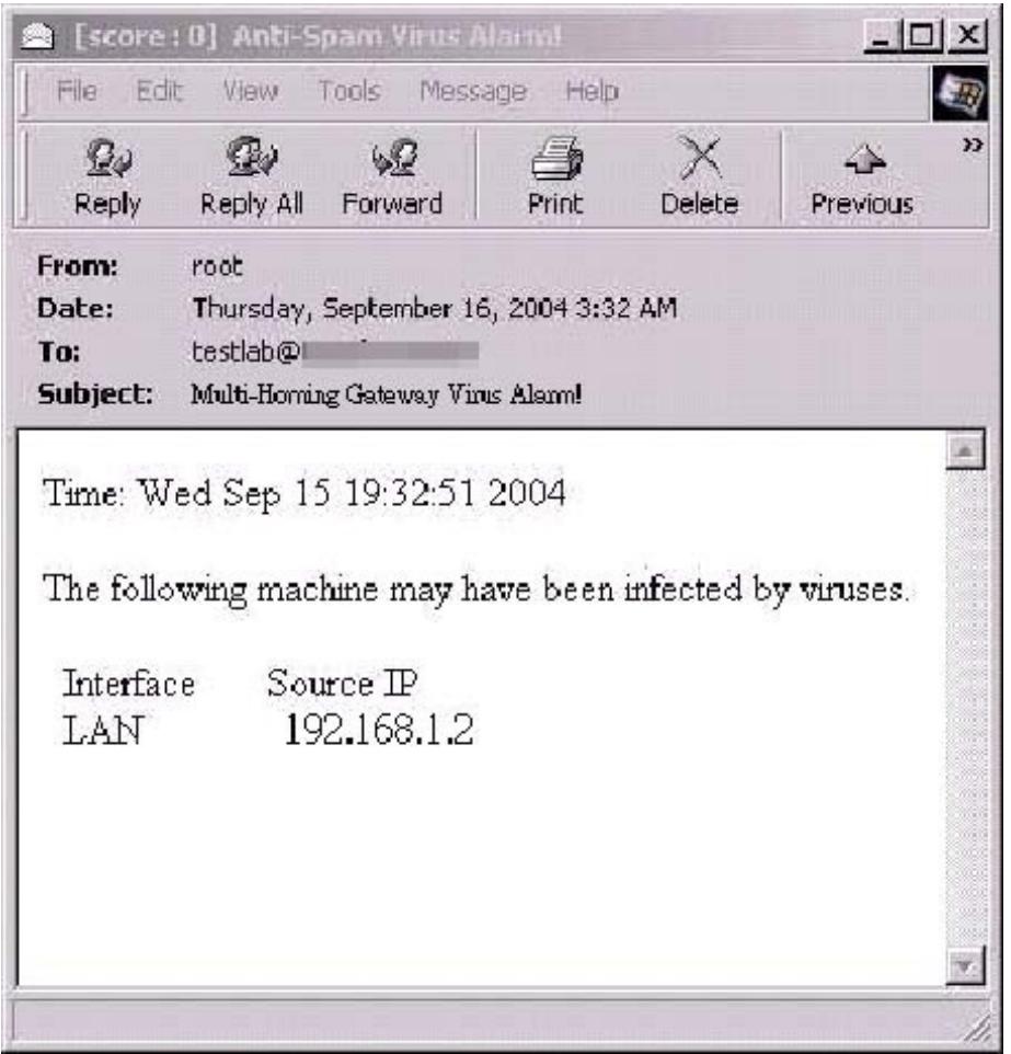
Figure16-5 E-mail Virus Alert
Chapter 14 Attack Alarm
Attack Alarm
SMC BR21VPN has two alarm forms: Internal Alarm, and External Alarm.
Internal Alarm: When the SMC BR21VPN had detected the internal PC sending large DDoS attacks and then the Internal Alarm will start on blocking these packets to maintain the whole network.
External Alarm: When SMC BR21VPN detects attacks from hackers, it writes attacking data in the External Alarm file and sends an e-mail alert to the Administrator to take emergency steps.

How to use Attack Alarm
The Administrator can be notified the unusual affair in Intranet from Attack Alarms. And the Administrator can backup the Internal Alarm, and External Alarm and then delete the records to maintain the network status.
| No. | Suitable Situation | Example | Page |
| Ex 1 | Internal Alarm | To record the DDoS attack alarm from internal PC | 192 |
| Ex 2 | External Alarm | To record the attack alarm about Hacker attacks the SMC BR21VPN and Intranet | 193 |
Internal Alarm
To record the DDoS attack alarm from internal PC
STEP 1. Select Internal Alarm in Attack Alarm when the device detects DDoS attacks, and then can know which computer is being affected. (Figure17-1)
Figure17-1 Internal Alarm WebUI
| Interface | Virus infected IP | Alarm Time |
| DMZ | 192.168.1.2 | 201-11-16 17:45:56 |
External Alarm
To record the attack alarm about Hacker attacks the SMC BR21VPN and Intranet
STEP 1 . Select the following settings in External Alert in Alert Setting function: (Figure17-2)
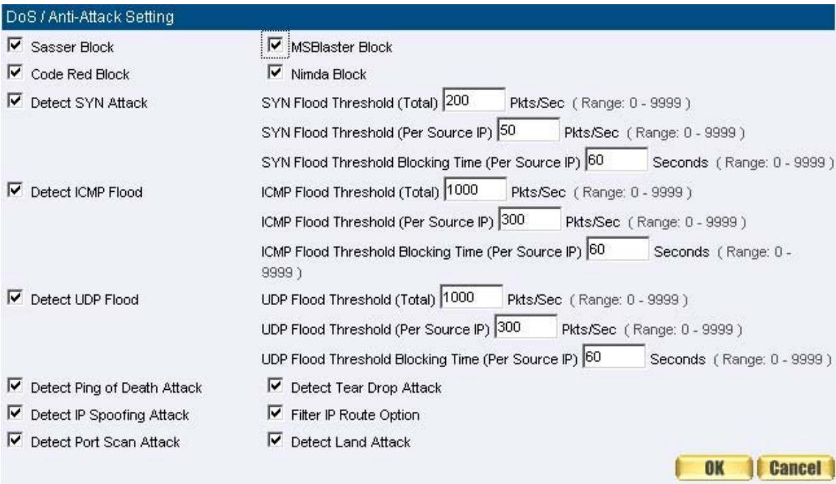
Figure17-2 External Alert Setting WebUI
Jul411:46:03
| Time | Event |
| Jul 411:46:03 | The system has detected the attack of TCP port scan, suspected to be 172.19.50.130 |
| Jul 411:45:46 | The system has detected the attack of TCP port scan, suspected to be 172.19.50.130 |
| Jul 411:45:32 | The system has detected the attack of TCP port scan, suspected to be 172.19.50.120 |
| Jul 411:45:27 | The system has detected the attack of TCP port scan, suspected to be 172.19.50.120 |
| Jul 411:45:24 | The system has detected the attack of TCP port scan, suspected to be 172.19.50.120 |
| Jul 411:45:06 | The system has detected the attack of TCP port scan, suspected to be 172.19.50.100 |
| Jul 411:45:02 | The system has detected the attack of TCP port scan, suspected to be 172.19.50.100 |
| Jul 411:44:59 | The system has detected the attack of TCP port scan, suspected to be 172.19.50.66 |
| Jul 411:44:48 | The system has detected the attack of TCP port scan, suspected to be 172.19.50.66 |
| Jul 411:44:45 | The system has detected the attack of TCP port scan, suspected to be 172.19.50.66 |
| Jul 411:44:34 | The system has detected the attack of TCP port scan, suspected to be 172.19.50.19 |
| Jul 411:44:28 | The system has detected the attack of TCP port scan, suspected to be 172.19.50.19 |
| Jul 411:44:25 | The system has detected the attack of TCP port scan, suspected to be 172.19.50.19 |
| Jul 411:41:58 | The system has detected the attack of TCP port scan, suspected to be 172.19.50.12 |
| Jul 411:39:50 | The system has detected the attack of TCP port scan, suspected to be 172.19.50.12 |
| Jul 411:37:21 | The system has detected the attack of TCP port scan, suspected to be 172.19.50.12 |
| Jul 411:37:16 | The system has detected the attack of TCP port scan, suspected to be 172.19.50.12 |
| Jul 411:37:16 | The system has detected the attack of TCP port scan, suspected to be 172.19.50.12 |
Clear Alarm
Download Alarms
Figure17-3 External Alarm WebUI
Chapter 15 LOG
LOG
Log records all connections that pass through the SMC BR21VPN's control policies. The information is classified as Traffic Log, Event Log, and Connection Log.
Traffic Log's parameters are setup when setting up policies. Traffic logs record the details of packets such as the start and stop time of connection, the duration of connection, the source address, the destination address and services requested, for each control policy.
Event Log record the contents of System Configurations changes made by the Administrator such as the time of change, settings that change, the IP address used to log in...etc.
Connection Log records all of the connections of SMC BR21VPN. When the connection occurs some problem, the Administrator can trace back the problem from the information.

How to use the Log
The Administrator can use the log data to monitor and manage the device and the networks. The Administrator can view the logged data to evaluate and troubleshoot the network, such as pinpointing the source of traffic congestions.
| No. | Suitable Situation | Example | Page |
| Ex 1 | Traffic Log | To detect the information and Protocol port that users use to access to Internet or Intranet by SMC BR21VPN. | 197 |
| Ex 2 | Event Log | To record the detailed management events (such as Interface and event description of SMC BR21VPN) of the Administrator | 202 |
| Ex 3 | Connection Log | To detect event description of WAN Connection | 205 |
| Ex 4 | Log Backup | To save or receive the records that sent by the SMC BR21VPN | 208 |
Traffic Log
To detect the information and Protocol port that users use to access to Internet or Intranet by SMC BR21VPN
STEP 1. Add new policy in DMZ to WAN of Policy and select Enable Logging: (Figure18-1)
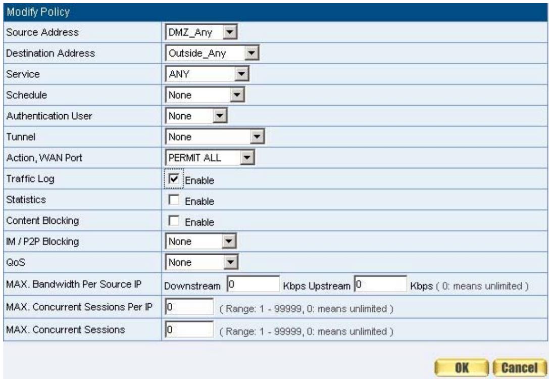
Figure18-1 Logging Policy Setting
STEP 2 . Complete the Logging Setting in DMZ to WAN Policy: (Figrule18-2)

Figure18-2 Complete the Logging Setting of DMZ to WAN
STEP 3. Click Traffic Log. It will show up the packets records that pass this policy. (Figure18-3)
Jul.412:02:59
Next
| Time | Source | Destination | Protocol | Port | Disposition |
| Jul 4 12:02:59 | 192.168.179.30 | 192.168.179.1 | TCP | 1549 => 80 | ✓ |
| Jul 4 12:02:58 | 192.168.179.30 | 192.168.179.1 | TCP | 1548 => 80 | ✓ |
| Jul 4 12:02:55 | 61.213.147.14 | 192.168.179.30 | TCP | 80 => 1546 | ✓ |
| Jul 4 12:02:55 | 192.168.179.30 | 61.213.147.14 | TCP | 1546 => 80 | ✓ |
| Jul 4 12:02:55 | 192.168.179.30 | 61.213.147.14 | TCP | 1546 => 80 | ✓ |
| Jul 4 12:02:55 | 61.213.147.14 | 192.168.179.30 | TCP | 80 => 1546 | ✓ |
| Jul 4 12:02:55 | 61.213.147.14 | 192.168.179.30 | TCP | 80 => 1546 | ✓ |
| Jul 4 12:02:55 | 192.168.179.30 | 61.213.14T.14.14 | TCP | 1546 => 80 | ✓ |
| Jul 4 12:02:55 | 192.168.179.30 | 61.213.147.14 | TCP | 1546 => 80 | ✓ |
| Jul 4 12:02:55 | 192.168.179.30 | 61.213.14T.14.14 | TCP | 1546 => 80 | ✓ |
| Jul 4 12:02:55 | 61.213.147.14 | 192.168.179.30 | TCP | 80 => 1546 | ✓ |
| Jul 4 12:02:55 | 61.213.147,14 | 192.168.179.30 | TCP | 80 => 1546 | ✓ |
| Jul 4 12:02:55 | 61.213.147.14 | 192.168.179.30 | TCP | 80 => 1546 | ✓ |
| Jul 4 12:02;55 | 61.213.147.14 | 192.168.179.30 | TCP | 80 => 1546 | ✓ |
| Jul 4 12:02:55 | 61.213.147.14 | 192.168.179.30 | TCP | 80 => 1546 | |
| Jul 4 12:02:55 | 61.213.147.14 | 192.168.179.30 | TCP | 80 => 1546 | |
| Jul 4 12:02:55 | 192.168.179.30 | 61.213.147.14 | TCP | 1546 => 80 | |
| Jul 4 12:02:55 | 192.168.179.30 | 61.213.147.14 | TCP | 1546 => 80 |
Clear Logs
Download Logs
Figure18-3 Traffic Log WebUI
STEP 4 . Click on a specific IP of Source IP or Destination IP in Figure18-3, it will prompt out a WebUI about Protocol and Port of the IP. (Figure18-4)
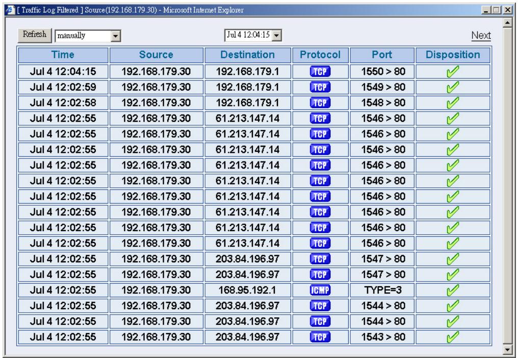
Figure18-4 The WebUI of detecting the Traffic Log by IP Address
STEP 5 . Click on Download Logs and select Save in File Download WebUI. And then choose the place to save in PC and click OK; the records will be saved instantly. (Figure18-5)
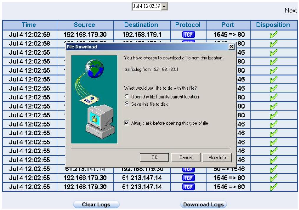
Figure18-5 Download Traffic Log Records WebUI
STEP 6 . Click Clear Logs and click OK on the confirm WebUI; the records will be deleted from the SMC BR21VPN instantly. (Figure18-6)
Jul.412:02:59
Next
| Time | Source | Destination | Protocol | Port | Disposition |
| Jul 4 12:02:59 | 192.168.179.30 | 192.168.179.1 | TCP | 1549 => 80 | ✓ |
| Jul 4 12:02:58 | 192.168.179.30 | 192.168.179.1 | TCP | 1548 => 80 | ✓ |
| Jul 4 12:02:55 | 61.213.147.14 | 192.168.179.30 | TCP | 80 => 1546 | ✓ |
| Jul 4 12:02:55 | 192.168.179.30 | 61.213.147.14 | TCP | 1546 => 80 | ✓ |
| Jul 4 12:02:55 | 192.168.179.30 | 61.213.147.14 | TCP | 1546 => 80 | ✓ |
| Jul 4 12:02:55 | 61.213.147.14 | 192.168.179.30 | TCP | 80 => 1546 | ✓ |
| Jul 4 12:02:55 | 61.213.147.14 | 192.168.179.30 | TCP | 80 => 1546 | ✓ |
| Jul 4 12:02:55 | 192.168.179 | Microsoft Internet Explorer | 1546 => 80 | ✓ | |
| Jul 4 12:02:55 | 192.168.179 | ? Do you really want to clean? | 1546 => 80 | ✓ | |
| Jul 4 12:02:55 | 192.168.179 | 1546 => 80 | ✓ | ||
| Jul 4 12:02:55 | 61.213.147.OK | Cancel | 80 => 1546 | ✓ | |
| Jul 4 12:02:55 | 61.213.147.14 | 80 => 1546 | ✓ | ||
| Jul 4 12:02:55 | 61.213.147.14 | 192.168.179.30 | 80 => 1546 | ✓ | |
| Jul 4 12:02:55 | 61.213.147.14 | 192.168.179.30 | 80 => 1546 | ✓ | |
| Jul 4 12:02:55 | 61.213.147.14 | 191.168.179.30 | 80 => 1546 | ✓ | |
| Jul 4 12:02:55 | 61.213.147.14 | 192.168.179.30 | 80 => 1546 | ✓ | |
| Jul 4 12:02:55 | 61.2.13.147.14 | 192.168.179.30 | 80 => 1546 | ✓ | |
| Jul 4 12:02:55 | 61.213.147.14 | 192.168.179.30 | 80 => 1546 | ✓ | |
| Jul 4 4 12:02:55 | 192.168.179.30 | 61.213.147.14 | 1546 => 80 | ✓ | |
| Jul 4 12:02:55 | 192.168.179.30 | 61.213.147.14 | 1546 => 80 | ✓ | |
Figure18-6 Clearing Traffic Log Records WebUI
Event Log
To record the detailed management events (such as Interface and event description of SMC BR21VPN) of the Administrator
STEP 1. Click Event log of LOG. The management event records of the administrator will show up (Figure18-7)
Jul 4 12:05:11
Next
| Time | Event |
| Jul 4 12:05:11 | admin WAN1 is disconnected |
| Jul 4 12:01:36 | admin WAN2 is connected |
| Jul 4 12:01:13 | admin Modify [WAN2 Interface] from 192.168.179.30 |
| Jul 4 12:00:50 | admin Modify [Policy](Outgoing,Inside_Any=>Outside_Any,ANY,permit1) from 192.168.179.30 |
| Jul 4 11:59:13 | admin Modify [WAN1 Interface] from 192.168.179.30 |
| Jul 4 11:58:26 | (null) Modify [WAN1 Interface] from 192.168.179.30 |
| Jul 4 11:50:33 | (null) WAN1 is connected |
| Jul 4 11:50:16 | (null) Modify [WAN1 Interface] from 192.168.179.30 |
| Jul 4 11:48:22 | (null) Remove [Mapped IP] (External IP : 172.19.0.2 Internal IP : 192.168.179.2) from 192.168.179.30 |
| Jul 4 11:39:09 | user admin [Login success] from 192.168.179.30 |
| Jul 4 11:36:07 | (null) Modify [Mapped IP] (External IP : 172.19.0.2 Internal IP : 192.168.179.2) from 172.19.50.12 |
| Jul 4 11:35:35 | (null) Add [Mapped IP] (External IP : 172.19.0.2 Internal IP : 12.168.179.2) from 172.19.50.12 |
| Jul 4 11:35:16 | (null) Remove [Virtual Server 1] from 172.19.50.12 |
| Jul 4 11:34:58 | (null) Add [Virtual Server 1] from 172.19.50.12 |
| Jul 4 11:34:09 | user admin [Login success] from 172.19.50.12 |
| Jul 4 11:32:56 | (null) WAN1 is disconnected |
| Jul 4 11:32:19 | (null) Modify [WAN1 Interface] from 192.168.179.30 |
| Jul 4 11:30:15 | (null) WAN1 is connected |
Clear Logs
Download Logs
Figure18-7 Event Log WebUI
STEP 2 . Click on Download Logs and select Save in File Download WebUI. And then choose the place to save in PC and click OK; the records will be saved instantly. (Figure18-8)
Jul 4 12:05:11
Next
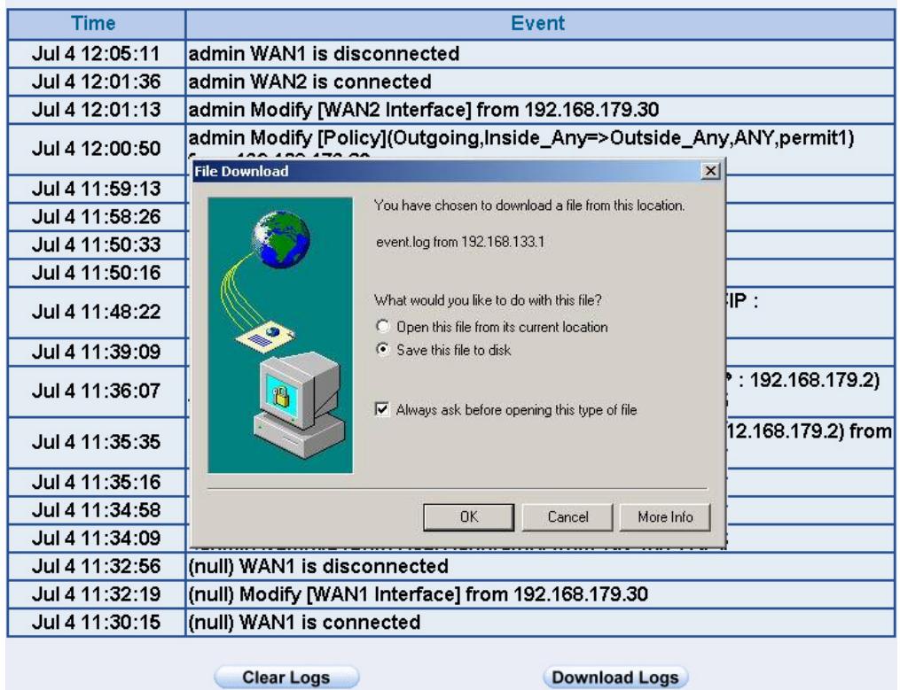
Figure18-8 Download Event Log Records WebUI
STEP 3 . Click Clear Logs and click OK on the confirm WebUI; the records will be deleted from the SMC BR21VPN. (Figure18-9)
Jul 4 12:05:11
Next
| Time | Event |
| Jul 4 12:05:11 | admin WAN1 is disconnected |
| Jul 4 12:01:36 | admin WAN2 is connected |
| Jul 4 12:01:13 | admin Modify [WAN2 Interface] from 192.168.179.30 |
| Jul 4 12:00:50 | admin Modify [Policy](Outgoing,Inside_Any=>Outside_Any,ANY,permit1) from 192.168.179.30 |
| Jul 4 11:59:13 | admin Modify [WAN1 Interface] from 192.168.179.30 |
| Jul 4 11:58:26 | {?}Modify [WAN1 Interface] from 192.168.179.30 |
| Jul 4 11:50:33 | {?}WAN1 is connected |
| Jul 4 11:50:16 | {?}Modify [Microsoft Internet Explorer ]x9.30 |
| Jul 4 11:48:22 | {?}Remove 192.168.179.2}Are you sure you want to remove ?9.0.2 Internal IP : |
| Jul 4 11:39:09 | user admin [LOKCancel]30 |
| Jul 4 11:36:07 | {?}Modify [from 172.19.50}0.2 Internal IP : 192.168.179.2) |
| Jul 4 11:35:35 | {?}Add [Mapped IP] (External IP : 172.19.0.2 Internal IP : 12.168.179.2) from 172.19.50.12 |
| Jul 4 11:35:16 | {?}Remove [Virtual Server 1] from 172.19.50.12 |
| Jul 4 11:34:58 | {?}Add [Virtual Server 1] from 172.19.50.12 |
| Jul 4 11:34:09 | user admin [Login success] from 172.19.50.12 |
| Jul 4 11:32:56 | {?}WAN1 is disconnected |
| Jul 4 11:32:19 | {?}Modify [WAN1 Interface] from 192.168.179.30 |
| Jul 4 11:30:15 | {?}WAN1 is connected |
Clear Logs
Download Logs
Figure18-9 Clearing Event Log Records WebUI
Connection Log
To Detect Event Description of WAN Connection
STEP 1 . Click Connection in LOG. It can show up WAN Connection records of the SMC BR21VPN. (Figure18-10)
Jul 3 19:41:14
Next
| Time | Connection Log |
| Jul 3 19:41:14 | Warning: couldn't open ppp database /var/run/pppd.tdb |
| Jul 3 19:41:14 | pppd 2.4.1 started by root, uid 0 |
| Jul 3 19:41:14 | tdbstore failed: Invalid tdb context |
| Jul 3 19:41:14 | Couldn't allocate PPP unit -1073449922 as it is already in use |
| Jul 3 19:41:14 | Using interface ppp0 |
| Jul 3 19:41:14 | tdbstore failed: Invalid tdb context |
| Jul 3 19:41:14 | PPPoE : Couldn't increase MTU to 1500 |
| Jul 3 19:41:14 | Couldn't increase MRU to 1500 |
| Jul 3 19:41:16 | local IP address 10.64.64.64 |
| Jul 3 19:41:16 | remote IP address 10.114.136.19 |
| Jul 3 19:41:16 | linkname : wan1 interface : ppp0 |
| Jul 3 19:41:20 | Sending PADI |
| Jul 3 19:41:20 | HOST_UNIQ successful match |
| Jul 3 19:41:21 | HOST_UNIQ successful match |
| Jul 3 19:41:21 | Got connection: 857 |
| Jul 3 19:41:21 | pads |
| Jul 3 19:41:21 | Connecting PPPoE socket: 00:90:1a:40:09:87 0857 eth1 0x53798 |
| Jul 3 19:41:21 | using channel 3 |
Figure18-10 Connection records WebUI
STEP 2 . Click on Download Logs and select Save in File Download WebUI. And then choose the place to save in PC and click OK; the records will be saved instantly. (Figure18-11)
Jul 3 1941:14
Next
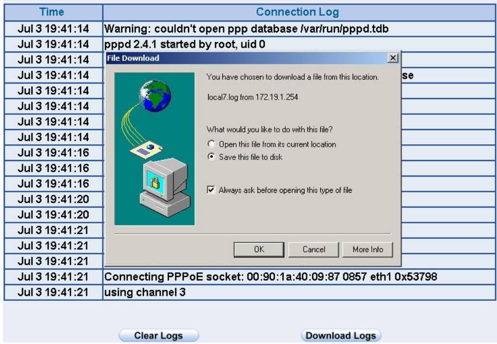
Figure18-11 Download Connection Log Records WebUI
STEP 3 . Click Clear Logs and click OK on the confirm WebUI, the records will be deleted from the SMC BR21VPN instantly. (Figure18-12)
Jul 3 19:41:14
Next
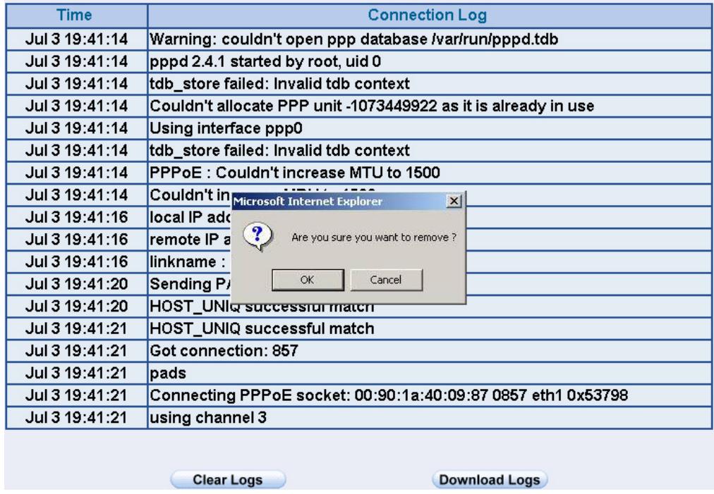
Figure18-12 Clearing Connection Log Records WebUI
Log Backup
To save or receive the records that sent by the SMC BR21VPN
STEP 1. Enter Setting in System, select Enable E-mail Alert Notification function and set up the settings. (Figrue18-13)
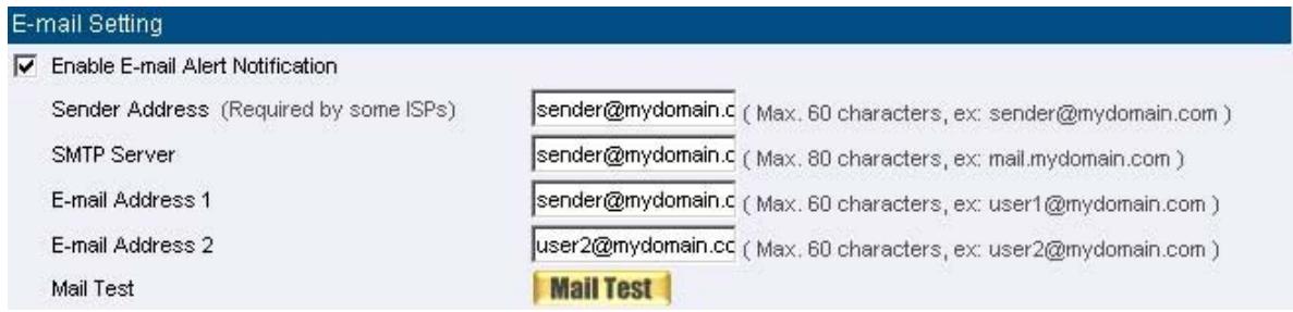
Figure18-13 E-mail Setting WebUI
STEP 2. Enter Log Backup in Log, select Enable Log Mail Support and click OK (Figure18-14)
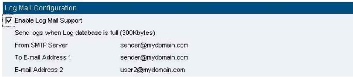
Figure18-14 Log Mail Configuration WebUI

After Enable Log Mail Support, every time when LOG is up to 300Kbytes and it
will accumulate the log records instantly. And the device will e-mail to the Administrator and clear logs automatically.
STEP 3. Enter Log Backup in Log, enter the following settings in Syslog Settings:
Select Enable Syslog Messages
Enter the IP in Syslog Host IP Address that can receive Syslog
Enter the receive port in Syslog Host Port
Click OK
Complete the setting (Figure18-15)
Syslog Setting
Enable Syslog Messages
Syslog Host IP Address
Syslog Host Port
192.168.1.61 (ex:192.168.1.61)
514 (Range:0-65535,ex:514)
OK
Cancel
Figure18-15 Syslog Messages Setting WebUI
Chapter 16 Accounting Report
Accounting Report
Administrator can use this Accounting Report to inquire the LAN IP users and WAN IP users, and to gather the statistics of Downstream/Upstream, First packet/Last packet/Duration and the Service of all the user's IP that passes the SMC BR21VPN.
Define the required fields of Accounting Report
Accounting Report Setting:
■ By accounting report function can record the sending information about Intranet and the external PC via SMC BR21VPN.
Accounting Report can be divided into two parts: Outbound Accounting Report and Inbound Accounting Report
Outbound Accounting Report
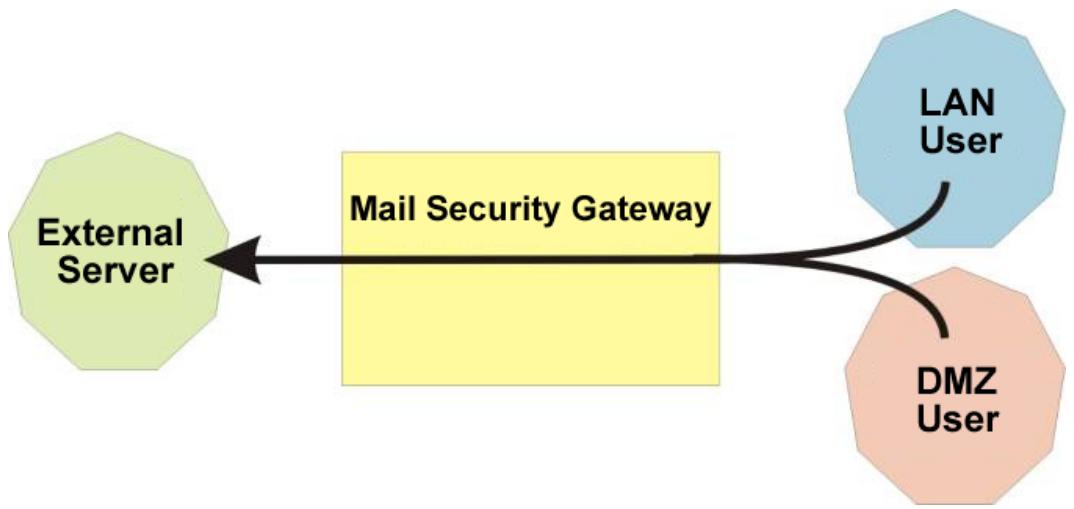
It is the statistics of the downstream and upstream of the LAN, WAN and all kinds of communication network services
Source IP :
The IP address used by LAN users who use SMC BR21VPN
Destination IP :
The IP address used by WAN service server which uses SMC BR21VPN.
Service:
The communication service which listed in the menu when LAN users use SMC BR21VPN to connect to WAN service server.
Inbound Accounting Report
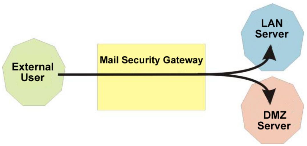
It is the statistics of downstream / upstream for all kinds of communication services; the Inbound Accounting report will be shown when WAN user uses SMC BR21VPN to connect to LAN Service Server.
Source IP :
The IP address used by WAN users who use SMC BR21VPN
Destination IP :
The IP address used by LAN service server who use SMC BR21VPN
Service:
The communication service which listed in the menu when WAN users use SMC BR21VPN to connect to LAN Service server.
Outbound
STEP 1. Enter Outbound in Accounting Report and select Top Users to inquire the statistics of Send / Receive packets, Downstream / Upstream, First packet/Last packet/Duration and the service from the LAN or DMZ user's IP that pass the SMC BR21VPN. (Figure19-1)
TOP: Select the data you want to view, it presents 10 results in one page.
Pull-down menu selection
Source IP : The IP address used by LAN users who use SMC BR21VPN to connect to WAN service server.
- Downstream: The percentage of downstream and the value of each WAN service server which uses SMC BR21VPN to LAN user.
■ Upstream : The percentage of upstream and the value of each LAN user who uses SMC BR21VPN to WAN service server.
- First Packet: When the first packet is sent to WAN service server from LAN user, the sent time will be recorded by the SMC BR21VPN.
- Last Packet: When the last packet sent from WAN service server is received by the LAN user, the sent time will be recorded by the SMC BR21VPN.
Duration : The period of time which starts from the first packet to the last packet to be recorded.
- Total Traffic : The SMC BR21VPN will record the sum of packet sent/receive time and show the percentage of each LAN user's upstream/downstream to WAN service server.
- Reset Counter : Click Reset Counter button to refresh Accounting Report.
| No. | Source IP | Downstream | Upstream | First Packet | Last Packet | Duration | Action | ||
| 1 | 192.168.100.2 | 114.9 KB | 100.0% | 4.6 MB | 100.0% | 01/01 00:08:19 | 01/01 00:08:23 | 00:00:04 | Remove |
| Total Traffic | 114.9 KB | 4.6 MB | Reporting time Fri Sep 2 09:13:21 2005 | ||||||
Reset Counter
Figure19-1 Outbound Source IP Statistics Report
STEP 2. Enter Outbound in Accounting Report and select Top Sites to inquire the statistics website of Send/Receive packets, Downstream/Upstream, First packet/Last packet/Duration and the service from the WAN Server to pass the SMC BR21VPN. (Figure19-2)
TOP : Select the data you want to view, it presents 10 results in one page.
Pull-down menu selection
- Destination IP: The IP address used by WAN service server which uses SMC BR21VPN.
- Downstream: The percentage of downstream and the value of each WAN service server which uses SMC BR21VPN to LAN user.
■ Upstream : The percentage of upstream and the value of each LAN user who uses SMC BR21VPN to WAN service server.
■ First Packet: When the first packet is sent from WAN service server to LAN users, the sent time will be recorded by the SMC BR21VPN. - Last Packet: When the last packet from LAN user is sent to WAN service server, the sent time will be recorded by the SMC BR21VPN.
Duration : The period of time which starts from the first packet to the last packet to be recorded.
Total Traffic : The SMC BR21VPN will record the sum of time and show the percentage of each WAN service server's upstream/downstream to LAN user. - Reset Counter: Click Reset Counter button to refresh Accounting Report.
| No. | Destination IP | Downstream | Upstream | First Packet | Last Packet | Duration | Action | ||
| 1 | 168.95.4.16 | 169.8 KB | 54.5% | 6.5 MB | 99.2% | 01/01 00:08:47 | 01/01 00:12:12 | 00:03:25 | Remove |
| 2 | 67.159.5.204 | 98.1 KB | 31.5% | 3.1 KB | 0.0% | 01/01 00:18:39 | 01/01 00:18:45 | 00:00:06 | Remove |
| 3 | 211.20.178.245 | 10.9 KB | 3.5% | 22.0 KB | 0.3% | 01/01 00:08:55 | 01/01 00:13:31 | 00:04:36 | Remove |
| 4 | 207.46.6.80 | 7.9 KB | 2.5% | 5.2 KB | 0.1% | 01/01 00:12:03 | 01/01 00:29:31 | 00:17:28 | Remove |
| 5 | 81.71.37.93 | 3.7 KB | 1.2% | 1.7 KB | 0.0% | 01/01 00:08:19 | 01/01 00:28:03 | 00:19:44 | Remove |
| 6 | 207.68.178.61 | 3.5 KB | 1.1% | 2.8 KB | 0.0% | 01/01 00:12:10 | 01/01 00:12:10 | 00:00:00 | Remove |
| 7 | 211.78.161.178 | 3.3 KB | 1.0% | 565.0 B | 0.0% | 01/01 00:12:16 | 01/01 00:12:16 | 00:00:00 | Remove |
| 8 | 65.54.183.192 | 2.7 KB | 0.9% | 1.3 KB | 0.0% | 01/01 00:12:04 | 01/01 00:12:04 | 00:00:00 | Remove |
| 9 | 203.73.24.185 | 1.8 KB | 0.6% | 553.0 B | 0.0% | 01/01 00:12:19 | 01/01 00:12:19 | 00:00:00 | Remove |
| 10 | 211.72.252.63 | 1.5 KB | 0.5% | 534.0 B | 0.0% | 01/01 00:12:20 | 01/01 00:12:20 | 00:00:00 | Remove |
| Total Traffic | 311.8 KB | 6.6 MB | Reporting time Fri Sep 2 09:32:31 2005 | ||||||
Reset Counter
Figure19-2 Outbound Destination IP Statistics Report
STEP 3. Enter Outbound in Accounting Report and select Top Services to inquire the statistics website of Send / Receive packets, Downstream/Upstream, First packet/Last packet/Duration and the service from the WAN Server to pass the SMC BR21VPN. (Figure19-3)
TOP : Select the data you want to view. It presents 10 results in one page.
: According to the downstream / upstream report of the selected TOP numbering to draw the Protocol Distribution chart. (Figure19-4)
Pull-down menu selection
Service : The report of Communication Service when LAN users use the SMC BR21VPN to connect to WAN service server.
- Downstream: The percentage of downstream and the value of each WAN service server who uses SMC BR21VPN to connect to LAN user.
■ Upstream : The percentage of upstream and the value of each LAN user who uses SMC BR21VPN to WAN service server.
■ First Packet: When the first packet is sent to the WAN Service Server, the sent time will be recorded by the SMC BR21VPN.
- Last Packet: When the last packet is sent from the WAN Service Server, the sent time will be recorded by the SMC BR21VPN.
Duration : The period of time starts from the first packet to the last packet to be recorded.
Total Traffic : The SMC BR21VPN will record the sum of time and show the percentage of each Communication Service's upstream/downstream to WAN service server.
Reset Counter : Click the Reset Counter button to refresh the
| No. | Service | Downstream | Upstream | First Packet | Last Packet | Duration | Action | ||
| 1 | SMTP [25] | 150.0 KB | 47.0% | 6.5 MB | 99.0% | 01/01 00:08:47 | 01/01 00:11:19 | 00:02:32 | Remove |
| 2 | HTTP [80] | 123.7 KB | 38.8% | 35.7 KB | 0.5% | 01/01 00:08:22 | 01/01 00:18:31 | 00:10:09 | Remove |
| 3 | POP3 [110] | 21.5 KB | 6.7% | 2.2 KB | 0.0% | 01/01 00:11:24 | 01/01 00:12:15 | 00:00:51 | Remove |
| 4 | MSN [1863] | 9.7 KB | 3.0% | 7.0 KB | 0.1% | 01/01 00:12:02 | 01/01 00:38:31 | 00:26:29 | Remove |
| 5 | UNKNOWN [4446] | 4.4 KB | 1.4% | 2.1 KB | 0.0% | 01/01 00:08:19 | 01/01 00:35:45 | 00:27:26 | Remove |
| 6 | HTTPS [443] | 2.7 KB | 0.8% | 1.4 KB | 0.0% | 01/01 00:08:21 | 01/01 00:12:04 | 00:03:43 | Remove |
| 7 | UNKNOWN [1368] | 1.2 KB | 0.4% | 1.2 KB | 0.0% | 01/01 00:08:25 | 01/01 00:36:38 | 00:28:13 | Remove |
| 8 | UNKNOWN [4652] | 1.2 KB | 0.4% | 1.7 KB | 0.0% | 01/01 00:08:25 | 01/01 00:36:13 | 00:27:48 | Remove |
| 9 | UNKNOWN [63756] | 549.0 B | 0.2% | 963.0 B | 0.0% | 01/01 00:08:25 | 01/01 00:36:38 | 00:28:13 | Remove |
| 10 | UNKNOWN [22453] | 500.0 B | 0.2% | 882.0 B | 0.0% | 01/01 00:08:25 | 01/01 00:36:39 | 00:28:14 | Remove |
| Total Traffic | 319.1 KB | 6.6 MB | Reporting time Fri Sep 2 09:42:01 2005 | ||||||
Figure19-3 Outbound Services Statistics Report
Service Distribution
| No. | Downstream | ||
| 1 | SMTP [25] | 150.0 KBytes (46.9%) | |
| 2 | HTTP [80] | 123.7 KBytes (38.7%) | |
| 3 | POP3 [110] | 21.5 KBytes (6.7%) | |
| 4 | MSN [1863] | 10.1 KBytes (3.2%) | |
| 5 | UNKNOWN [4446] | 4.4 KBytes (1.4%) | |
| 6 | HTTPS [443] | 2.7 KBytes (0.8%) | |
| 7 | UNKNOWN [4652] | 1.6 KBytes (0.5%) | |
| 8 | UNKNOWN [1368] | 1.2 KBytes (0.4%) | |
| 9 | UNKNOWN [63756] | 549.0 Bytes (0.2%) | |
| 10 | UNKNOWN [22453] | 500.0 Bytes (0.2%) | |
| OTHER | 3.6 KBytes (1.1%) | ||
Upstream
| 1 | SMTP [25] | 6.5 MBytes (99.0%) | |
| 2 | HTTP [80] | 35.7 KBits (0.5%) | |
| 3 | MSN [1863] | 7.7 KBits (0.1%) | |
| 4 | POP3 [110] | 2.2 KBits (0.0%) | |
| 5 | UNKNOWN [4446] | 2.1 KBits (0.0%) | |
| 6 | UNKNOWN [4652] | 2.1 KBits (0.0%) | |
| 7 | UNKNOWN [3198] | 1.6 KBits (0.0%) | |
| 8 | HTTPS [443] | 1.4 KBits (0.0%) | |
| 9 | UNKNOWN [1368] | 1.2 KBits (0.0%) | |
| 10 | UNKNOWN [63756] | 963.0 Bytes (0.0%) | |
| OTHER | 15.7 KBits (0.2%) |
Figure19-4 According to the downstream / upstream report of the selected TOP numbering to draw the Protocol Distribution chart
Inbound
STEP 1. Enter Inbound in Accounting Report and select Top Users to inquire the statistics website of Send / Receive packets, Downstream / Upstream, First packet/Last packet / Duration and the service from the WAN user to pass the SMC BR21VPN. (Figure19-5)
TOP: Select the data you want to view. It presents 10 pages in one page.
Select from the Pull-down menu
Source IP: The IP address used by WAN users who use SMC BR21VPN.
Downstream : The percentage of Downstream and the value of each WAN user who uses SMC BR21VPN to LAN service server.
■ Upstream : The percentage of Upstream and the value of each LAN service server who uses SMC BR21VPN to WAN users.
■ First Packet: When the first packet is sent from WAN users to LAN service server, the sent time will be recorded by the SMC BR21VPN.
- Last Packet: When the last packet is sent from LAN service server to WAN users, the sent time will be recorded by the SMC BR21VPN.
Duration : The period of time starts from the first packet to the last packet to be recorded.
- Total Traffic : The SMC BR21VPN will record the sum of time and show the percentage of each WAN user's upstream / downstream to LAN service server.
- Reset Counter : Click the Reset Counter button to refresh the Accounting Report.
| No. | Source IP | Upstream | Downstream | First Packet | Last Packet | Duration | Action | ||
| 1 | 172.19.1.106 | 4.6 KB | 85.5% | 820.0 B | 52.0% | 01/01 03:34:46 | 01/01 03:34:46 | 00:00:00 | Remove |
| 2 | 172.19.50.25 | 448.0 B | 8.1% | 420.0 B | 26.6% | 01/01 03:59:20 | 01/01 03:59:21 | 00:00:01 | Remove |
| 3 | 172.19.50.35 | 128.0 B | 2.3% | 120.0 B | 7.6% | 01/01 04:00:04 | 01/01 04:00:04 | 00:00:00 | Remove |
| 4 | 172.19.50.30 | 128.0 B | 2.3% | 120.0 B | 7.6% | 01/01 03:59:52 | 01/01 03:59:53 | 00:00:01 | Remove |
| 5 | 172.19.50.159 | 96.0 B | 1.7% | 96.0 B | 6.1% | 01/01 03:59:30 | 01/01 03:59:31 | 00:00:01 | Remove |
| Total Traffic | 5.4 KB | 1.5 KB | Reporting time Mon Sep 5 14:24:19 2005 | ||||||
Reset Counter
Figure19-5 Inbound Top Users Statistics Report
Enter Inbound in Accounting Report and select Top Sites to inquire the statistics website of Send / Receive packets, Downstream / Upstream, First packet/Last packet / Duration and the service from the WAN user to pass the SMC BR21VPN. (Figure19-6)
TOP: Select the data you want to view. It presents 10 pages in one page.
Pull-down menu selection
- Destination IP : The IP address used by WAN users who uses SMC BR21VPN.
Downstream : The percentage of Downstream and the value of each WAN user who uses SMC BR21VPN to LAN service server.
■ Upstream : The percentage of Upstream and the value of each LAN service server who uses SMC BR21VPN to WAN users.
■ First Packet: When the first packet is sent from WAN users to LAN service server, the sent time will be recorded by the SMC BR21VPN.
- Last Packet: When the last packet is sent from LAN service server to WAN users, the sent time will be recorded by the SMC BR21VPN.
Duration : The period of time starts from the first packet to the last packet to be recorded.
Total Traffic : The SMC BR21VPN will record the sum of time and show the percentage of each WAN user's upstream / downstream to LAN service server.
- Reset Counter : Click the Reset Counter button to refresh the Accounting Report.
| No. | Destination IP | Downstream | Upstream | First Packet | Last Packet | Duration | Action | |
| 1 | 192.168.1.2 | 1.6 MB | 31.7% | 213.9 KB | 22.0% | 01/01 00:15:42 | 01/01 03:45:02 | 03:29:20 |
| 2 | 192.168.1.3 | 956.6 KB | 18.3% | 29.2 KB | 3.0% | 01/01 01:14:07 | 01/01 04:05:15 | 02:51:08 |
| 3 | 192.168.1.4 | 535.4 KB | 10.2% | 255.0 KB | 26.3% | 01/01 03:24:08 | 01/01 03:33:07 | 00:08:59 |
| 4 | 192.168.1.5 | 478.8 KB | 9.1% | 38.2 KB | 3.9% | 01/01 00:15:40 | 01/01 03:45:16 | 03:29:36 |
| 5 | 192.168.1.20 | 313.6 KB | 6.0% | 10.4 KB | 1.1% | 01/01 01:12:42 | 01/01 04:04:38 | 02:51:56 |
| 6 | 192.168.1.21 | 310.7 KB | 5.9% | 96.3 KB | 9.9% | 01/01 02:34:33 | 01/01 02:38:24 | 00:03:51 |
| 7 | 192.168.1.28 | 270.7 KB | 5.2% | 65.9 KB | 6.8% | 01/01 01:27:54 | 01/01 01:31:58 | 00:04:04 |
| 8 | 192.168.1.126 | 112.5 KB | 2.1% | 9.5 KB | 1.0% | 01/01 02:35:01 | 01/01 02:46:25 | 00:11:24 |
| 9 | 192.168.1.220 | 90.5 KB | 1.7% | 9.4 KB | 1.0% | 01/01 01:13:07 | 01/01 01:13:56 | 00:00:49 |
| 10 | 192.168.1.236 | 82.4 KB | 1.6% | 2.9 KB | 0.3% | 01/01 02:35:06 | 01/01 02:43:15 | 00:08:09 |
| Total Traffic | 5.1 MB | 971.3 KB | Reporting time Mon Sep 5 14:29:18 2005 | |||||
Reset Counter
Figure19-6 Inbound Destination IP Statistics Report
STEP 2. Enter Inbound in Accounting Report and select Top Services to inquire the statistics website of Send/Receive packets, Downstream/Upstream, First packet/Last packet/Duration and the service from the WAN Server to pass the SMC BR21VPN. (Figure19-7)
TOP : Select the data you want to view. It presents 10 results in one page.
: According to the downstream / upstream report of the selected TOP numbering to draw the Protocol Distribution chart. (Figure19-8)
Pull-down menu selection
Service : The report of Communication Service when WAN users use the SMC BR21VPN to connect to LAN service server.
Downstream : The percentage of downstream and the value of each WAN user who uses SMC BR21VPN to LAN service server.
■ Upstream : The percentage of upstream and the value of each LAN service server who uses SMC BR21VPN to WAN user.
■ First Packet: When the first packet is sent to the LAN Service Server, the sent time will be recorded by the SMC BR21VPN.
- Last Packet: When the last packet is sent from the LAN Service Server, the sent time will be recorded by the SMC BR21VPN.
Duration : The period of time starts from the first packet to the last packet to be recorded.
Total Traffic : The SMC BR21VPN will record the sum of time and show the percentage of each Communication Service’s upstream / downstream to LAN service server.
- Reset Counter : Click the Reset Counter button to refresh the Accounting Report.
| No. | Service | Upstream | Downstream | First Packet | Last Packet | Duration | Action | |||||
| 1 | HTTP [80] | 904.4 KB | 59.2% | 84.6 KB | 86.1% | 01/01 03:34:46 | 01/01 04:06:19 | 00:31:33 | Remove | |||
| 2 | FTP-DATA [20] | 622.5 KB | 40.7% | 12.5 KB | 12.8% | 01/01 04:39:31 | 01/01 04:42:23 | 00:02:52 | Remove | |||
| 3 | FTP [21] | 1.7 KB | 0.1% | 1.1 KB | 1.1% | 01/01 04:39:30 | 01/01 04:39:30 | 00:00:00 | Remove | |||
| Total Traffic | 1.5 MB | 98.2 KB | Reporting time Mon Sep 5 15:11:28 2005 | |||||||||
Reset Counter
Figure19-7 Inbound Services Statistics Report

Figure19-8 According to the downstream / upstream report of the selected TOP numbering to draw the Protocol Distribution chart
Service Distribution
| No. | Downstream | ||
| 1 | HTTP [80] | 904.4 KBytes (59.0%) | |
| 2 | FTP-DATA [20] | 622.5 KBytes (40.6%) | |
| 3 | FTP [21] | 5.3 KBytes (0.3%) | |
| OTHER | 0.0 Bytes (0.0%) | ||
| No. | Upstream | |||
| 1 | HTTP [80] | 84.6 KBytes (83.8%) | ||
| 2 | FTP-DATA [20] | 12.5 KBytes (12.4%) | ||
| 3 | FTP [21] | 3.8 KBytes (3.8%) | ||
| OTHER | 0.0 Bytes (0.0%) | |||
Chapter 17 Statistics
Statistics
WAN Statistics: The statistics of Downstream / Upstream packets and Downstream/Upstream traffic record that pass WAN Interface
Policy Statistics: The statistics of Downstream / Upstream packets and Downstream/Upstream traffic record that pass Policy
In this chapter, the Administrator can inquire the SMC BR21VPN for statistics of packets and data that passes across the SMC BR21VPN. The statistics provide the Administrator with information about network traffics and network loads.
Define the required fields of Statistics:
Statistics Chart:
Y-Coordinate: Network Traffic (Kbytes/Sec)
X-Coordinate : Time (Hour/Minute)
Source IP, Destination IP, Service, and Action:
These fields record the original data of Policy. From the information above, the Administrator can know which Policy is the Policy Statistics belonged to.
Time:
To detect the statistics by minutes, hours, days, months, or years.
Bits/sec, Bytes/sec, Utilization, Total:
The unit that used by Y-Coordinate, which the Administrator can change the unit of the Statistics Chart here.
Utilization: The percentage of the traffic of the Max. Bandwidth that System Manager set in Interface function.
Total: To consider the accumulative total traffic during a unit time as Y-Coordinate
WAN Statistics
STEP 1. Enter WAN in Statistics function, it will display all the statistics of Downstream/Upstream packets and Downstream/Upstream record that pass WAN Interface. (Figure20-1)
Figure20-1 WAN Statistics function
| WAN | Time |
| WAN 1 | Minute Hour Day Week Month Year |
| WAN 2 | Minute Hour Day Week Month Year |
| All WAN Interface | Minute Hour Day Week Month Year |
Time: To detect the statistics by minutes, hours, days, months, or years.

WAN Statistics is the additional function of WAN Interface. When enable WAN
Interface, it will enable WAN Statistics too.
STEP 2. In the Statistics window, find the network you want to check and click Minute on the right side, and then you will be able to check the Statistics figure every minute; click Hour to check the Statistics figure every hour; click Day to check the Statistics figure every day; click Week to check the Statistics figure every week; click Month to check the Statistics figure every month; click Year to check the Statistics figure every year.
STEP 3. Statistics Chart (Figure20-2)
Y-Coordinate : Network Traffic ( Kbytes/Sec )
X-Coordinate : Time (Hour/Minute)
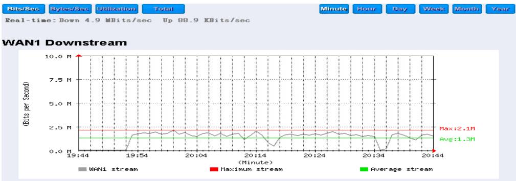
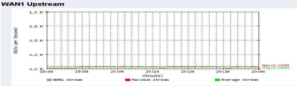
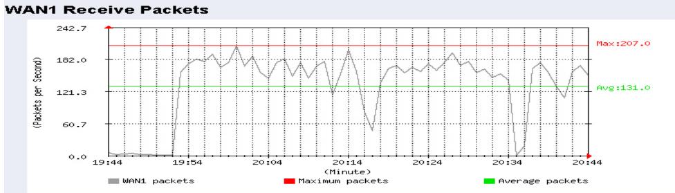
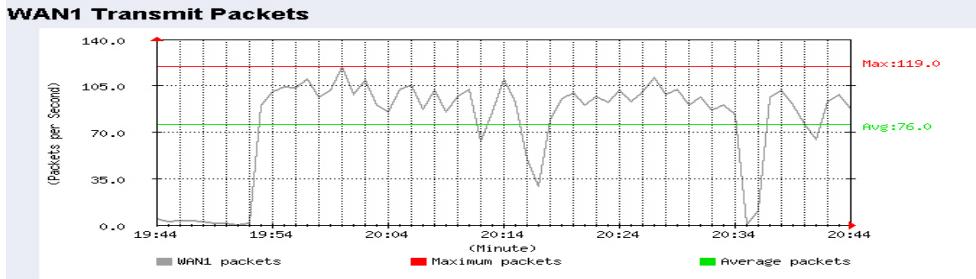
Figure20-2 To Detect WAN Statistics
Policy Statistics
STEP 1. If you had select Statistics in Policy, it will start to record the chart of that policy in Policy Statistics. (Figure20-3)
Figure20-3 Policy Statistics Function
| Source | Destination | Service | Action | Time | |||||
| Inside_Any | Outside_Any | ANY | Minute | Hour | Day | Week | Month | Year | |
| DMZ_Any | Outside_Any | ANY | Minute | Hour | Day | Week | Month | Year | |

If you are going to use Policy Statistics function, the System Manager has to enable the Statistics in Policy first.
STEP 2. In the Statistics WebUI, find the network you want to check and click Minute on the right side, and then you will be able to check the Statistics chart every minute; click Hour to check the Statistics chart every hour; click Day to check the Statistics chart every day; click Week to check the Statistics figure every week; click Month to check the Statistics figure every month; click Year to check the Statistics figure every year.
STEP 3. Statistics Chart (Figure20-4)
Y-Coordinate: Network Traffic (Kbytes/Sec)
X-Coordinate : Time (Hour/Minute/Day)
Bits/Sec
Bytes/Sec
Total
Inside_Any to Outside_Any
Service: ANY
Action: PERMIT
Minute
Hour
Day
Week
Month
Yea
Real-time: Down 3.4 MBits/sec
Up 63.0 KBits/sec
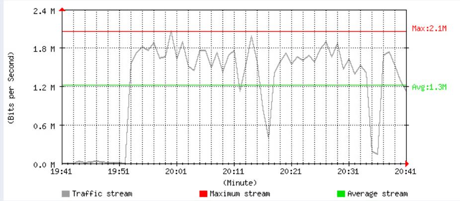
Downstream
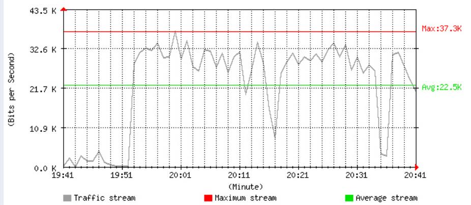
Upstream
Figure20-4 To Detect Policy Statistics
Chapter 18 Status
Status
The users can know the connection status in Status. For example: LAN IP, WAN IP, Subnet Netmask, Default Gateway, DNS Server Connection, and its IP...etc.
■ Interface: Display all of the current Interface status of the SMC BR21VPN
Authentication: The Authentication information of SMC BR21VPN
ARP Table: Record all the ARP that connect to the SMC BR21VPN
- DHCP Clients: Display the table of DHCP clients that are connected to the SMC BR21VPN.
Interface
STEP 1. Enter Interface in Status function; it will list the setting for each Interface: (Figure21-1)
PPPoE Con. Time: The last time of the SMC BR21VPN to be enabled
MAC Address: The MAC Address of the Interface
IP Address/ Netmask: The IP Address and its Netmask of the Interface
- Rx Pkts, Err. Pkts: To display the received packets and error packets of the Interface
- Tx Pkts, Err. Pkts: To display the sending packets and error packets of the Interface
■ Ping, WebUI: To display whether the users can Ping to the SMC BR21VPN from the Interface or not; or enter its WebUI
Forwarding Mode: The connection mode of the Interface
■ Connection Status: To display the connection status of WAN
DnS/ UpS Kbps: To display the Maximum DownStream/UpStream Bandwidth of that WAN (set from Interface)
DnStream Alloca.: The distribution percentage of DownStream according to WAN traffic
- UpStream Alloca.: The distribution percentage of UpStream according to WAN traffic
Default Gateway: To display the Gateway of WAN
DNS1: The DNS1 Server Address provided by ISP
DNS2: The DNS2 Server Address provided by ISP
| LAN | WAN1 | WAN2 | DMZ | |
| Forwarding Mode | NAT | Static IP | Static IP | Transparent |
| WAN Connection | --- | # | # | --- |
| Max. Downstream / Upstream | --- | 512 / 512 Kbps | 50000 / 50000 Kbps | --- |
| Downstream Alloca. | --- | 0% | 100% | --- |
| Upstream Alloca. | --- | 41% | 58% | --- |
| PPPoE Con. Time | --- | --- | --- | --- |
| MAC Address | 00:e0:98:00:00:09 | 00:e0:98:00:00:0a | 00:e0:98:00:00:b | 00:e0:98:00:00:c |
| IP Address | 192.168.159.1 | 61.11.11.12 | 211.22.22.22 | 0.0.0.0 |
| Netmask | 255.255.255.0 | 255.255.255.0 | 255.255.255.0 | 0.0.0.0 |
| Default Gateway | --- | 61.11.11.254 | 211.22.22.254 | --- |
| DNS1 | --- | 168.95.1.1 | 168.95.1.1 | --- |
| DNS2 | --- | 0.0.0.0 | 0.0.0.0 | --- |
| Rx Pkts, Error Pkts | 98471, 0 | 0, 0 | 2408, 0 | 0, 0 |
| Tx Pkts, Error Pkts | 12173, 0 | 13068, 0 | 15066, 0 | 15112, 0 |
| Ping | ✓ | ✓ | ✓ | ✓ |
| HTTP | ✓ | ✓ | ✓ | ✓ |
Figure21-1 Interface Status
Authentication
STEP 1. Enter Authentication in Status function, it will display the record of login status: (Figure21-2)
IP Address: The authentication user IP
- Auth-User Name: The account of the auth-user to login
- Login Time: The login time of the user (Year/Month/Day Hour/Minute/Second)
Figrue21-2 Authentication Status WebUI
| IP Address | Authentication-User Name | Login Time |
| 192.168.179.30 | josh | 2003/1/1 0:18:10 |
ARP Table
STEP 1. Enter ARP Table in Status function; it will display a table about IP Address, MAC Address, and the Interface information which is connecting to the SMC BR21VPN: (Figure21-3)
NetBIOS Name: The identified name of the network
IP Address: The IP Address of the network
MAC Address: The identified number of the network card
Interface: The Interface of the computer
Anti-ARP virus software Download Comment
TotalMACs:1

Figure21-3 ARP Table WebUI
DHCP Clients
STEP 1. In DHCP Clients of Status function, it will display the table of DHCP Clients that are connected to the SMC BR21VPN: (Figure21-4)
IP Address: The dynamic IP that provided by DHCP Server
MAC Address: The IP that corresponds to the dynamic IP
Leased Time: The valid time of the dynamic IP (Start/End) (Year/Month/Day/Hour/Minute/Second)
Figure21-4 DHCP Clients WebUI
| IP Address | MAC Address | Leased Time | |
| Start | End | ||
| 192.168.179.2 | 00:0c:76:b7:97:7e | 2003/1/1 0:9:49 | 2003/1/2 0:9:49 |
| 192.168.179.4 | 56:49:54:41:4c:bd | 2003/1/1 0:4:54 | 2003/1/2 0:4:54 |
TECHNICAL SUPPORT
From U.S.A. and Canada (24 hours a day, 7 days a week)
Phn: (800) SMC-4-YOU / (949) 679-8000
Fax: (949) 679-1481
ENGLISH
Technical Support information available at www.smc.com
FRENCH
E-mail address: techsupport@smc.com
Driver updates
http://www.smc.com/index.cfm?action tech_support_drivers_downloads
World Wide Web
http://www.smc.com/