FLEXSCAN L661 - Monitor EIZO - Free user manual and instructions
Find the device manual for free FLEXSCAN L661 EIZO in PDF.
Download the instructions for your Monitor in PDF format for free! Find your manual FLEXSCAN L661 - EIZO and take your electronic device back in hand. On this page are published all the documents necessary for the use of your device. FLEXSCAN L661 by EIZO.
USER MANUAL FLEXSCAN L661 EIZO
2-1 How to use the ScreenManager … About ScreenManager ScreenManager Menus . How to use the ScreenManaget Adjustment Lock 2-2 Screen Adjustment About Screen Adjustments Adjustment Procedure 2-3 Color Adjustment About Color Adjustments Color Mode … Gain Adjustments 2-4 Power-save Setup Setup Procedure 2-5 Other Settings About Other Settings Screen Size … Border intensity Input Priority . Off Timer Beep … Menu Position Reset CONTENTS
Setup Procedure Trouble Shooting 4 TROUBLESHOOTING 37 5 CLEANING 41 6 SPECIFICATIONS 42 APPENDIX i Pin Assignment … Preset Timing Chart …… Dimensions … Copyright© 2000 by EIZO NANAO CORPORATION. All rights re rved. No part of this manual may be reproduced, stored in a retrieval system, or transmitted, in any form or by any means, electronic, mechanical, or otherwise, without the prior written permission of Eizo Nanao Corporation. Eizo Nanao Corporation is under no obligation to hold any submitted material or information confidential unless prior arrangements are made pursuant to Fizo Nanao Corporation's receipt of said information. Although every effort has been made to ensure that this manual provides up-to-date information, please note that EIZO monitor specifications are subject to change without notice. Apple and Macintosh are trademarks of Apple Computer Inc..registered in the U.S. and other countries. DPMS is a trademark and VESA is a registered trademark of Video Electronics Standards Association. VGA is a registered trademark of International Business Machines Corporation in the USA and other countries. ENERGY STAR is a US. registered mark. Windows is a registered trademark of Microsoft Corporation. ScreenManager, PowerManager, and Sound are trademarks of Eizo Nanao Corporation. FlexScan and EIZO are registered trademarks of Eizo Nanao Corporation. CONTENTS 3
- The manufacturer is not responsible for damage or malfunction caused by improper connection. The power cord should be connected directly to a standard wall power outlet. Location of the caution statements on the back panel. CAUTON:_Fisk of ect shock, Do no open ATTENTION. isaue de choc electrique. Ne pas ouvi. ÂÀ ACHTUNG: Gala des alskiisehen schlages. Rückwan nie entemen. Te eut must De GOneGIRG 15 à EURE mai GUEL order stKKoOntAKT Skaï benylies nar apparatet HIKODIeS datanet, Apparaten SkaÎ ansiutas I Jordat natutiag. IMPORTANT! To ensure personal safety and proper maintenance. Please read this section and the caution statements on the LCD monitor (refer to the figure above). This manual uses the safety symbols below. They denote critical information. Please read them carefully. S Indicates a prohibited action. e@) Indicates to ground for safety. VAN WARNING Failure to abide by the information in a WARNING may result in serious injury and can be life threatening, À CAUTION Failure to abide by the information in a CAUTION may result in moderate injury and/or property or product damage. 4 PRECAUTIONS
À WARNING If the LCD monitor begins to emit smoke, smells like something is burning, or makes strange noises, disconnect all power connections immediately and contact your dealer for advice. Attempting to use a malfunctioning LCD monitor can be dangerous. Do not dismantle the cabinet or modify the LCD monitor. Dismantling the cabinet or modifying the monitor may result in electric shock or burn. Keep small objects away from the LCD monitor. Small objects may accidentally fall through the ventilation slots into the cabinet-leading to fire, shock or equipment damage. Keep liquids away from the LCD monitor. Spillage into the cabinet may result in fire, electric shock, or equipment damage. If an object or liquid falls/spills into the cabinet, unplug the LCD monitor immediately. Have the unit checked by a qualified service engineer before using it again. Do not touch a damaged LCD panel directly with bare hands. Use protective gloves whenever handling a damaged panel. The liquid erystal which leaks from the panel is poisonous if it enters the eyes or mouth. If any part of the skin or body comes in direct contact with the panel, please wash thoroughly. If some physical symptoms result, please consult your doctor. Take care in disposing of the LCD monitor. The backlight of the LCD monitor contains mercury. Follow local regulations or laws for safe disposal. Use the enclosed power cord. If using the power cord other than the enclosed one, use the following cord. In USA and Canada, use a UL LISTED/CSA LABELED or CERTIFIED power cord set meeting the following specifications:
- Rating: min.125V10A * Length: max. 2.0m
- Plug type: NEMA 5-15P, Parallel blade, Grounding type, 125 V, 10 À In Europe, use a proper European meeting the following, specification
- Rating: min. 250V,10A * Length: max. 2.0m
- Type: HOSWV-F 3G 1 mm° Use a plug type approved by the country where you use Failure to do so may cause fire or electric shock. andard approved power cord PRECAUTIONS 5
The equipment must be connected to a grounded main outlet. Failure to do this may result in an electric shock. Handle the power cord with care.
- Do not place the cord underneath the LCD monitor or other heavy objects.
- Do not pull on the cord.
- Do not bend, bundle or tie up the cord.
- Never attempt to repair a damaged cord. If the power cord becomes damaged, stop using it. Use of a damaged cord may result in fire or electric shock. To disconnect the power cord, grasp the plug firmly and pull. Never tug on the cord, doing so may cause damage and could result in fire or electric shock. Use the correct voltage. The LCD monitor is designed for use with a specific voltage only. Connection to a different voltage may cause fire, electric shock, or other damage. Do not overload your power circuit, as this may result in fire or electric shock. To ensure proper connections of the power cord, be certain to plug the power cord into the provided LCD monitor connector and directly to a wall outlet. By not doing so may result in fire or electric shock. Keep the plastic packing bags away from children and infants. Plastic bags can be dangerous. To avoid danger of suffocation, keep the bag away from babies and children. Place the LCD monitor on a strong, stable surface. — A unit placed on an inadequate surface may fall, resulting in injury or equipment damage. If the LCD monitor falls, disconnect the power immediately and have the unit checked by a qualified service engineer before using it again. Using a LCD monitor after it has been dropped may result in fire or electric shock. When attaching the monitor to the mount, use the enclosed screws and tighten them securely. When reattaching the monitor to the tilt stand, use the screws that was attached to the monitor originally. By not doing so may result in injury or failure of the monitor To attach the mount to the monitor, please read the instruction manual of the mount. 6 PRECAUTIONS
+ Set the LCD monitor in an appropriate location.
- Do not install in a dusty or humid environment. Do not place near water. Do not place in a location where light shines directly on the screen. Do not place near heat generating devices or a humidifier. À CAUTION At the end of the day, or if you plan to leave the LCD monitor unused for an extended period, turn off the main power switch and disconnect the power cord from the wall socket so that no power connections are made. To ensure safety, always unplug the LCD monitor before cleaning it. Cleaning the LCD monitor while it is plugged into a power outlet may result in electric shock. Never use thinner, benzene, or other strong solvents or abrasive cleaners, as these may cause damage to the cabinet or LCD panel. Periodically clean the area around the plug. Build-up of dust, water, or oil on the plug may result in fire. Please keep the LCD monitor in a dust-free environment. Dust accumulation within the LCD monitor may result in fire or equipment failure. Do not touch the plug or the power unit with wet hands. Touching the plug with wet hands is dangerous and can cause electrical shock. When handling the LCD monitor, please refer to the diagram. Grip the bottom of the LCD monitor firmly with both hands ensuring the panel faces outward before lifting. Handle with care to avoid scratching or damaging the panel. If the LCD monitor becomes damaged, disconnect the power immediately and have the unit checked by a qualified service engineer before using it again. Using a LCD monitor after it has been dropped may result in fire or electric shock. Disconnect the power cord when moving the LCD monitor. Moving the LCD monitor with the cord attached or lifting it is dangerous. Ie may result in injury or equipment damage. PRECAUTIONS 7
+ Use an easily accessible power outlet. This will ensure that you can disconnect the power quickly in case of a problem. Do not block the ventilation slots on the cabinet.
- Do not place books or any other papers on the ventilation slots.
- Do not install the monitor in a closed space.
- Do not use the monitor laying down or upside down.
- Do not remove the tilt-swivel stand. D Using the monitor in this way blocks the ventilation slots and prevents proper airflow, leading to fire or other damage. Others + The screen may have some defective pixels. These pixels may appear as slightly light or dark areas on the screen. This is due to the characteristics of the panel itself, and not the LCD product. The backlight of the LCD monitor has a fixed life span. When the screen becomes dark or begins to flicker, please contact your dealer. Take care when handling the LCD panel.
- Do not press on the panel or edge of the frame strongly as this will result in damage to the screen. There will be prints left on the screen if the pressed image is dark or black. Decrease of the prints on the screen requires to keep white desktop patterns on for L661, and black desktop pattern's on for L680.
- Do not scratch or press on the panel with any sharp objects, such as pencil or pen as this may result in damage to the panel. Cleaning the panel with a dirty or rough cloth may damage the panel. Generally, for maximum viewing comfort position the LCD monitor slightly below eye level. Staring at the LCD monitor for prolonged periods can cause eye strain. Be sure to take adequate rests. (À 10-minute rest period each hour is suggested.) 8 PRECAUTIONS
INTRODUCTION About This Manual This manual explains the precautions, features, specifications, and operation of your EIZO LCD monitor. For convenience, a “ScreenManager Quick Reference” guide has been included which shows how to implement basic adjustments with the ScreenManager utility. Package Contents LCD Monitor Viewing Angle L660 L661 L680 Horizontal: 160° 140° 170° Vertical: 160° 140° 170° ScreenManager Quick Reference Power Cord
Connector Cover Rear Cover attached to the monitor)
Users Manual Signal Cable (MD-C87/100)
4 of 4 mm x 12 mm mounting screws
Warranty Registration Card + _ lfany ofthe above-listed items are missing or damaged, please contact your local dealer for assistance. + We recommend that you retain the original packing materials in case of future need. INTRODUCTION
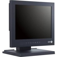
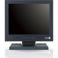
Controls & Connectors Enter Button Control Buttons Up, down, right and left buttons are used to enter adjustments and settings when using the ScreenManager menu. Front Power Button Switches the monitors power ON and OFF only when the main power is ON. Power Indicator Power is ON ge Poweris switching off in 15 minutes (See page 32.) Terminal Yellow (Solid): Power Saving Mode Covers for (Flashing}:_ Power is OFF the Optional (Main powers ON.) peripheral Auto Adjustment Button Automatically centers the displayed image and adjust Clock and phase. Input Signal Selection Button Selects one oftwo D-Sub connectors as the active input. Rear Power Power 4 Holes for Mounting an Arm-Stand Switch Connector 2 x D-Sub mini 15 pin Input Connectors Maintenance Port Service use only. l USB Ports (Upstream Port x 1) | On USB ports, see page 34 for further details. Security Lock “14 Allows for connection of a security cable. This lock supports the Kensington’s MicroSaver security system. For further information, please consult below: Kensington Technology Group 2855 Campus Drive, San Mateo, CA 94403 USA 800-650-4242, x3348 Intl: 650-572-2700, x3348 Fe 650-572-9675 http/wwwkensington.com USB Ports {Downstream Port x 4) 1 0 INTRODUCTION
INSTALLATION 1-1 Connecting up PC Settings Before connecting your PC to the LCD monitor, change the display screen settings (resolution and frequency) in accordance with those below. fH: 27 kKHz-82 kHz fV: 50 Hz-85 Hz + The maximum resolution of this LCD monitor is 1280 x 1024 ata maximum fV of 75 Hz. Using the LCD monitor with Windows® 95/98 A Monitor information file is saved in the EIZO LCD Utility Disk included in the package. It includes all the LCD required information for best operation with Windows 95/98. Please install the enclosed utility and select “EIZO L660/L661/L680” from the monitor list in Windows 95/98. For installation procedure, please read the readme.txt in the utility disk. Connecting the Cables (1) Be sure that the power switches of both the PC and the LCD monitor are OFE (2)Remove the rear cover from the monitor. When removing the rear cover, push down the buttons while pulling. (3)Plug the signal cable into the D-Sub connector at the rear of the monitor. Please ensure that the arrow mark on the casing of the connector is visible when connecting. When connecting the signal cable, check that the shape of the cable connector matches the shape on the LCD monitor. 1 INSTALLATION 11 [FT
(4) Plug the other end of the cable into the video connector on the rear of the PC. Standard PC graphics board D-Sub minitS pin Ps Standard PC graphics board Signal Cable (enclosed) Macintosh JP-Sub minits [on ns Macintosh G3 = : (Blue & White) Signal Cable (enclosed) D-Sub minitS pin D-Sub minit5 D-Sub 15 pin pin Macintosh Signal Cable (enclosed) ae ‘Adapter DSCR-153 (optional) (5)Plug the power cord into the power connector on the rear of the LCD monitor. (6)Replacing the connector cover and the rear cover. a) Insert the rear cover into the inlets at the bottom of the stand. b) To close easily, the LCD monitor should be tilted forward. Attach the connector cover to the rear panel of the LCD. (7)Plug the other end of the power cord into a power outler. (8) Turn on the monitors main power and then switch on the PC power. Whenever you finish your operation, turn off the PC and the monitor. INSTALLATION
+. Do your part to conserve energy, turn off the monitor when you E are finished using it. — Attaching an Arm Stand to the Monitor À WARNING + When attaching the monitor to the mount, use the enclosed screws and tighten them securely. When reattaching the monitor to the tilt stand, use the screws that was attached to the monitor. By not doing so may result in injury or failure of the monitor. To attach the mount to the monitor, please read the instruction manual of the mount. NOTE + Use a VESA approved arm-stand. The LCD panel requires 100 mm x 100 mm hole spacing 100 mm on the arm mounting pad. The arm-stand should be able to support an object weighing 13.5 kg. + _In case of using this LCD monitor with an arm- stand in an office workspace, the arm-stand shall be chosen and used carefully: - Use only an approved arm-stand (e.g. GS). - The arm-stand shall have sufficient stability (mechanical firmness) to support the weight of the monitor. - The arm-stand shall remain in that position (Example) where it is manually moved. - The arm-stand shall have the ability to tilt the  monitor forward and backward. Il - The height of the upper row shall be less | than or equal to 500 mm in relation to 600 mm | the desk surface when the arm-stand is in its lowest position. (1)Lay the LCD monitor as shown below, not scratching the panel. Remove the tilt loosening the screws. When reattaching the tilt, use the enclosed screws and fix the tilt to the monitor securely.
(2)Place and fix a mount or an arm-stand to the monitor securely. Mounting Screws T4 (enclosed): 4x12 (mm) Connecting two PCs to the Monitor (Example) Macintosh Adapter ? Î JE DSCR-153 (optional) PC compatible |nE J & ET Apple N 7 Macintosh Signal Cable (Enclosed) The EIZO L660/L661/L680 has two video input signal connectors (2 x D-sub mini 15 pin). The priority switch system allows the user to assign priority to either input signal. + Contact EIZO dealers for information about optional cables. +_Be sure that the monitor and the PC are both switched off before connecting them. Selecting the Active Input Input Signal Selection Button + The Input signal selection button on the front panel can be used to select Signal 1 or Signal 2 as the active input. + The ScreenManager “Input Priority” setting (in the “Others” menu) can be used to set up the automatic selection of the input. See page 31 for details. 14 1 INSTALLATION
2-1 How to use the ScreenManager About ScreenManager As shown on the display, the ScreenManager is used to adjust the LCD monitor. Adjustments are made using the Enter and Control buttons (up, down, right and left) located on the front panel. rimes Enter Button Control Buttons ScreenManager Menus Screen Manager consists of a main menu and six sub menus: “Screen”, “Color”, “PowerManager”, “Others”, “Information” and “Language.” Animated icons on each menu allows for casy adjustment. Main menu ScreenManager” 20 6ee
<Screen> NOTE + The menu message for the ScreenManager can be displayed in six fe languages: English, German, French, Italian, Spanish and Swedish. Primary setting is English. For details, please refer to the next page.
Sub menus Functions Reference <Screen> page 19 <Color> page 26 <PowerManager> page 28 <Others> page 30 ŒÆ signa 1 640«480 31.5kHz 60:0Hz <information> This menu shows the current SereenManager settings. The menu contains three pages. Pressing the ENTER key displays the following information: + Page 1: “Screen” menu settings + Page 2: “Color” and “PowerManager” settings + Page 3: “Others” menu settings The current ScreenManager setting is displayed even if the input selection has been manually overridden by the use of the input signal selection button. @ Language @English ODeutsen QFrançais OEspañol Oltaliano O8venska <Language> Hirst select the preferred language to use. The ScreenManager*s messages will appear in the selected language. This will become the default language when you use the ScreenManager.
How to use the ScreenManager Entering the ScreenManager Push the Enter button once to display the main menu of the ScreenManager. Enter the Settings (1) To enter any sub menu icon, highlight the desired icon by using the Control buttons (up, down, right and left) and push the Enter button. The sub menu appears. (2) Use the Control buttons to select the desired setting icon and push the Enter button. (8) The setting menu appears. Use the Control buttons to make all required adjustments. Exit the ScreenManager ()To return to the main menu, select the “Return” icon or push the down button twice, followed by the Enter button. (2) To save and exit the ScreenManager, select the “Exit” icon and push the Enter button. Double clicking the Enter button at any time also exits the ScreenManager menu. + Leaving the ScreenManager idle for 45 seconds or more will turn the adjustment off automatically, without the adjustment's saved.
Shortcut keys Brightness and contrast can be adjusted directly without any necd to enter the ScreenManager. Press the Control buttons to adjust the settings and then the Enter button to save all changes. Sce the diagram below for adjustment directions. The brightness and contrast functions are also available in the ScreenManager “Screen” menu. Brightness Contrast
Brightness down Adjustment Lock Auto Adjustment button | Power Button The ScreenManager operation can be disabled by holding down the Auto adjustment button while switching on the LCD monitor power. This will disable (“lock”) the Enter button and Auto adjustment button, protecting from accidental changes. To unlock the buttons, switch the power off. Switch the power on while pressing the Auto adjustment button. Note the brightness and contrast can be adjusted using the shorteut keys even while the Enter button is locked. After making such an adjustment, the Enter button can be used to clear the brighness/contrast adjustment menu from the screen. Furthermore, the Input signal selection button can still be used while the adjustment lock is on.
2-2 Screen Adjustment About Screen Adjustments Entering the ScreenMananger, select the “Screen” icon and push the Enter button to show the “Screen” menu. gere {Sereen» <Clock> “Screen” adjustments for the LCD monitor should be used in suppressing screen flickering and also for adjusting the screen to its proper position. There is only one correct position for each display mode. Ir is also recommended to use the ScreenManager function when first installing the display or whenever changing the system. For convenience, an casy set-up Program installed on the utility disk to assist in the set-up procedure is provided. For set up sce the next page. The following common display modes have been preset in the LCD monitors memory, and require no screen adjustment. If the mode input to the LCD monitor is not one of the preset modes, the adjustments must be made using the Auto adjustment button and ScreenManager “Screen” menu. Mode 640 x 480 (-85 Hz) VGA 720 x 400 (70 Hz) 800 x 600 (-75 Hz) Apple Macintosh 832 x 624 (75 Hz) 1024 x 768 (-85 Hz) Apple Macintosh 1152 x 870 (75 Hz) Sun WS 1152 x 900 (-76 Hz) 1280 x 960 (-85 Hz) 1280 x 1024 (-75 Hz) wlo|s|olu|zs|o ln |
Adjustment Procedure Overview (1) Install and run the "Screen Adjustment Program" in the utility disk. (2) Push the Auto adjustment button.
(8) Enter the ScreenManager and select the "Screen" menu. (4) [O] "Clock" adjustment Horizontal bars appear. | OK (5) "Phase" adjustment "Position" adjustment Contfirm the "Resolution. (8) «| "Contrast/Brightness" adjustment
(9) Exitthe ScreenManager. + Allow the LCD monitor to warm up for at least 20 minutes before making adjustments. + To make adjustment easily, install and run the “Screen Adjustment Program” in the attached utility disk. Before adjustment, read the “readme.txt” file. + Do not continuously press the Control buttons (up, down, right and left buttons) on the front panel, as the adjustment value will change quickly and make it difficult to locate the most suitable adjustment point.
Procedure Please adjust the screen using the following procedure. (1)Having read the “readme.txt” file, install and run the “Screen Adjustment Program” in the utility disk. Step by step adjustment is provided by the wizard guide. Follow the wizard or the procedures (2) ro (8) below. NOTE + _lfthe user's operation system has no utility disk (e.g. OS/2), we recommend setting the desktop pattern to that as shown in the diagram below. Every-other-dot pattern
(2) Auto Adjustment Push the Auto adjustment button on the front panel. The following message will appear and remain on the screen for 5 seconds. While the message is on the screen, push the button again to automatically adjust the screen position. If you do not wish to do adjust the screen, do not push the button again. The message will disappear. Your Setting will be lost, if you press again nou. + _ The Auto adjustment function is intended for use on Macintosh and PCs running Windows. lt may not function properly if any of the following applies: + PC running MS-DOS (not Windows). +_ The background color for the “wallpaper” or “desktop” pattern is set to black or dark. + Some signals from some graphics boards may not function properly. Follow the adjustment procedure next page. +. During the Auto adjustment, some icons (e.g. clock icon) appear on the screen continuously.
(3) Enter the ScreenManager “Screen” menu. (4) “Clock” Adjustment Function Decreases the vertical bars of distortion. a)Select the “Clock” icon and push the Enter button to enter the “Clock” menu” b}If vertical bars appear, these can be eliminated by adjusting the right and left buttons.
i) If the screen is free from any bars of distor-
tion, proceed to “Position” adjustment. ä)If horizontal flickering or horizontal bars appear, proceed to “Phase” adjustment. + The LCD monitor is designed for analog input signals from a standard graphics board. The analog input signal is converted to a digital signal by the LCD circuitry. To convert the signal correctly, the LCD monitor needs to produce the same number of clock pulses as the dot clock of the graphics system. When the clock pulse is not correctly set, some vertical bars of distortion are displayed on the screen. + When adjusting the “Clock”, the horizontal screen size will also change.
(5) “Phase” Adjustment Function Eliminates the horizontal bars of distortion. a)Select the “Phase” icon and push the Enter button to show the “Phase” menu. b)If horizontal bars appear, these can be eliminated by adjusting the right and left buttons. c) After finishing the adjustment, push the Enter button to memorize the settings and return to the “Screen” menu. - “Phase” adjustments should be done after adjusting the “Clock”. - Horizontal bars may not completely disappear from the screen depending on the PC. - The phase adjustment decides the sampling point for converting the analog input signal to a digital signal. Adjusting the “Phase” after the “Clock” adjustment will produce a clear screen. (6) Position Adjusment
Function Controls the screen position. a)Select the “Position” icon and push the Enter button to enter the “Position menu. Adjustment markers are displayed on each corner of the screen. b) Ajust the position of the upper left corner of the image using the Control buttons in order to align the screen. - If vertical bars of distortion appear after finishing the “Position” adjustment, return to “Clock” menu and repeat the previously explained adjustment procedure (‘Clock” “Phase” “Position").
(7) “Resolution” Adji ustment Funci Controls the contrast of the screen. a)Select the “Contrast” icon and push the Enter button to show the “Contrast/Brightness” menu. b) Confirm if the resolution now being displayed is the same as the input resolution. If it is not, adjust the vertical resolution using the up and down button and adjust the horizontal resolution using the right and left buttons. c) After finishing the adjustment, push the Enter button to memorize the settings and return to the “Screen” menu. Smaller than the actual screen images. Adjusted to actual screen size. Larger than the actual screen images. (8) “Contrast” Adjustment
10% Function Controls the contrast of the screen. a) Select the “Contrast” icon and push the Enter button. b)Press the Auto adjustment button on the front panel while displaying the “Contrast/Brightness menu to automatically adjust contrast. €) The screen blanks for a moment and adjusts the contrast to the maximum level of the current input signal. (continued) w Too High Too Low
- In the case of the percentage color flickering between yellow and white, please note that this is not an error but actually the most optimum adjustment point.
- The brightness of the entire screen is controlled by changing the “Brightness” controls. No contrast adjustment is required except when the graphics board or the resolution is changed from the previous one. d) Adjust the “Brightness” as desired using the up and down button. €) After finishing the adjustment, push the Enter button to memorize the settings and return to the “Screen” menu. (9) Exit the ScreenManager a) To return to the main menu, select the “Return” icon or push the down button twice, followed by the Enter button. b) To exit the ScreenManager, select the “Exit” icon and push the Enter button. Double clicking the Enter button at any time also exits the ScreenManager menu. +_Inthe “Enlarged” mode and the “Full” mode (refer to the page 30), the following adjustment is available. EE] Smoothing Function Displays blurred texts distinct. -This adjustment is disable when the resolution is 1280 x 1024 or 1280 x 960.
2-3 Color Adjustment About Color Adjustments Entering the ScreenManager, select the “Color” icon and push the enter button to show the “Color” menu. eve" CREER
<Color> <Color MHode> The SereenManager “Color” menu provides 3 color setting modes; 1, 2, and 3. You can also adjust the color settings for each mode and store them for future use. + Allow the monitor to warm-up for at least 20 minutes before making an adjustment. Color Mode Function Color Mode | Adjusts: Color Mode (Standard) ! Mode 1(default): | The normal white color. It is the maximum contrast level. Please use this mode normally. Mode 2: The white color tone is slighely bluish. Mode 3: The white color tone is slightly reddish. - The contrast level is reduced in Mode 2 and 3. {a) Select the “Color Mode” icon from the “Color” menu and push the Enter button. (b) Select option 1, 2 or 3 and push the Enter button. A long beep will be heard indicating the adjustment settings have been saved.
Gain Adjustments By adjusting the red, green and blue color tones for each mode, custom colors can be defined. Please use this function when high precision color adjustment is required. + _ Before you attempt to change the colors, always start with the color settings set to the default setting by using the “Reset” icon in each color mode. o Gain Function Adjusts: Gain Gain The Gain adjustment has no effect on the starting point (the black level). Ie changes only the ending point (the white level). The Gain adjustment is used to fine tune the whites and light grays to an even balance. a) Select the “Gain” icon. The screen shown on the left will appear. Adjust each color until you can create a uniform white screen. To register the adjustment, select the “Save” icon and then push the Enter button. If the settings are not saved, all adjustments will be lost.
Finally, readjust the contrast in the “Screen” menu to get the best image clarity. + The adjustment works effectively only when the percentages appear black. Magenta percentage means the colors saturation. Lower the percentage till its color becomes black. - After making the color settings, readjust the contrast to get the best definition and color intensity for the displayed image. - “Reset” You can recall the default color gain setting for the current color mode (1, 2, 3) using the “Reset” icon. + The values shown in percentages represent the current level within the specific adjustment only. They are available only as a reference tool. (To create a uniform white or black screen, the percentages for each will probably not be the same.)
Function El PowerManager| Power saving adjustment The EIZO PowerManager functions comply with the VESA DPMS standard and adopt a power saving method, EIZO MPMS. , As an Energy Star® Partner, Eizo Nanao {arfift Corporation has determined that this product meets the Energy Star guidelines for energy efficiency. + Do your part to conserve energy, turn off the monitor when you are finished using it. Discon- necting the monitor from the power supply is recommended to save energy completely. + When the monitor is in a power saving mode, the optional EIZO i-Sound speaker unit will turn off. + Even if the monitor is in a power saving mode, USB compliant devices function when they are connected to the monitors USB (both the upstream and the downstream ports). Therefore, power consumption of the monitor will change according to the connected devices even if the monitor is in a power saving mode. Set-up Procedure “VESA DPMS” system works with the VESA DPMS signal. “EIZO MPMS” system works with a screen saver software and EnergySaver for Macintosh which blanks the screen (totally black screen).
1) Set the monitor to match the PCs power saving software, as follows.
For the PC setup, please refer to the users manuals of the PC and the graphics board. Monitor setting for matching the PC: PC PC Power saving Monitor setting PC/AT and compatibles VESA DPMS (Signal) VESA DPMS (VESA DPMS activated) PC/AT and compatibles Windows EIZO MPMS (VESA DPMS {Control Panel/Display/ inactivated) ScreenSaver: “Blank Screen”) Macintosh Energy Saver EIZO MPMS ScreenSaver software EIZO MPMS After Dark/*Blank” settings
+. When“VESA DPMS'is selected, the monitor shifts into the power saving mode in 5 seconds after recognizing either STAND-BY, SUSPEND, OR OFF signal. When “EIZO MPMS’is selected, the monitor shifts into the power saving mode in 5 seconds after PC's ScreenSaver blanks the screen. BVESA DPMS Power Saving Method VESA DPMS utilizes four signals: ON, STANDBY, SUSPEND, and OFE The monitor derects these signals from the graphics board and executes power saving accordingly, as illustrated below. Signal Screen LED Power Consumption ON Operation Green 59 W(L660), 47 W(L661) 67 WIL680) STAND-BY/ [Blank (power | Yellow less than 3 W SUSPEND/OFF|saving mode) MEIZO MPMS power saving method If the keyboard or the mouse are not in use during operation, the monitor willenter PowerManager Mode Signal Screen LED Power Consumption ON Operation Green 59 W(L660), 47 W(L661) 67 W(L680) After Blank (power | Yellow less than 3 W Duration saving mode) What is VESA DPMS? The acronym VESA stands for “Video Electronics Standards Association,” and DPMS stands for “Display Power Management Signaling.” DPMS is a communication standard that PCs and graphics boards use to implement power savings at the monitor side. What is EIZO MPMS? EIZO MPMS, "EIZO Monitor PowerManager Signaling", also enables to execute power saving at the monitor side. ELZO MPMS recognizes the video signals from the PC when the PC is in a power saving mode, and reduces energy consumption of the monitor. What is Energy Star? “Energy Star” is a ser of power-saving guidelines issued by the U.S. Environmental Protection Agency (EPA). The guidelines apply to PC systems and peripherals.
(Others) Others © Pi
<Screen Size)» All of the icons shown in the ScreenManager “Others” menu are described below. Screen Size
é e % <Scroon Size) Function Selects Screen Size There are three screen size as follows. Full Displays the picture on the screen in full, Screen … | irrespective of the picture's resolution. Since the vertical resolution and the horizontal resolution are enlarged in different rates, some images may appear distorted. Enlarged | Displays the picture on the screen in full, Screen | consideringthe width ofthe screen. Since the pixel elements are fixed, some lines of the characters or pictures may be displayed with a different width. Normal | Displays the picture at the actual Screen | resolution Normal Enlarged Full 640 x 480 1280 x 960 1280 x 1024 1024 x 768 1280 x 960 1280 x 1024 - The resolution of 1280 x 960 and 1280 x 1024 do not change the screen sizes in the full screen or the enlarged screen mode. - Atthe ‘“Enlarged” mode, “Smoothing" adjustment is available for having the blurred letters distinct. Please refer to the page 25.
Border intensity Border Intonsity> Function Changes the brightness of the black area surrounding the displayed image. - This adjustment is disable in full screen mode. What is the “Border Intensity” function? With lower resolutions of (640 x 480, 800 x 600, 1024 x 768, etc.) the image is displayed at the center of the screen and the outer area (border usually black. The “Border Intensity” function can set the brightness of this border area to any brightness level that maybe desired. Input Priority
81 02 OManual Selects which PC will have priority to control the monitor when utilizing two PCs. Priority | Performance setting If signals from both inputs are present, the monitor gives preference to Signal 1 for the cases shown below: + When the power of the monitor is turned] ON (see note 1). + When the signal input to Signal 1 is changed even if active input was Signal 2. Signal 1 If signals from both inputs are present, the monitor gives preference to Signal 2 for thel cases shown below: Signal 2|+ When the power of the monitor is turned] ON (see note 1). + When the signal input to Signal 2 is changed even if active input was Signal 1. The monitor will not detect signals automatically in this mode. Select the activ input by pressing the input signal selection button on the monitors front panel. Manual Off Timer ÉLET
<OFE Timor? Automatically Turns off the Monitor What is Off Timer? The Off Timer function allows the user to set the time in which the monitor will be in operation, called the “On Period” and automatically shifts the operation into the “Power Off” mode when the set “On Period” expires. The Off Timer function was created to reduce afterimage characteristics that are particular to LCD monitors when the monitor screen is left on for a long period without use.
Function “others” menu. to exit the ScreenManager. modes . as desired.
3) Press the righv/left key to adjust how long (1 to 23
hours) the monitor should be in the “On Period”. Then, press the enter button to return to the
4) Select the “Exit” icon and push the Enter button
Advance notice (Beep and LED flashing green) will be given 15 minutes before the monitor will automatically turn off and enter the “Power Off” - “Off Timer” function works while Power Manager is active, but there would be no advanced mode before the monitors power switching off. To Delay Entering Power Off To delay entering the “Power Off” mode, press the power button on the front panel located to the left of the LED light during the advance notice period. The monitor will continue to operate for an additional 90 minutes. There will be another advance notice for 15 minutes as described. Delayed entrance into the “Power Off” period can be extended as many times Cat) Beep Turns the beeper on or off. Short beep| ScreenManager item selected. ee : ScreenManager parameter adjt e to minimum or maximum li <heo> - Input signal selection button pressed. Long beep| + Auto Adjustment button pressed. + ScreenManager data-save executed. beeps |: PC turned off. frequency. Four short] : Monitor not connected correctly. + Monitor received unsupported signal fifteen seconds Two short|: Monitor is in the advance notice mode beeps | ofthe Off Timer. The power will be every | _off within fifreen minutes.
This monitor provides a hub which supports the USB standard. When connecting to a USB compliant PC or another hub, the monitor functions as a hub to which the USB compliant peripherals can be easily connected. Required system environment + PCequipped with USB ports or another USB hub connected to the USB compliant PC + Windows 98/2000 / Mac OS 8.5.1 or later + USB cable (Sold separately) +__The USB hub function may not work properly depending on the PC, OS or peripherals. Please consult the manufacturer of each device about the USB support. + Whenthe monitoris not on, the peripherals connected to the down- stream ports will not operate. + Evenifthe monitor is in a power saving mode, the devices connected to the monitors USB ports (both the upstream and the downstream) will function. Connecting to the USB HUB + Do not connect the downstream port of the monitor to any peripherals until finishing the USB function. + The followings are procedures for the Windows 98 Second Edition/2000 and Mac OS.
1) Connect the monitor to the PC with the signal cable (See page 11) first,
then turn on the PC.
2) Connect the upstream port ofthe monitor to the downstream port of the
USB compliant PC or another hub by using the USB cable .
| x Upstream connector | Ÿ stream A Jr. | Ports Upstream Port: c : Connect the USB compliant To Dounstream Ports! PC or another hub using the ofthe PC or Another USB cable. Hub After connectiong the USB cable, the USB function can be set up automatically.
3) After setting up, the monitors USB hub is available for connecting USB
compliant peripherals to the downstream ports of the monitor. (Example of connection) _— —7/Monitor Scanner Digital Camera Downstream connector Downstream ports: Connect the cables from USB compliant peripherals such as a mouse, keyboard, etc.
Troubleshooting Problems USB function cannot be setup. Points to check with possible solutions D Check that the USB cable is correctly connected. D Check that the PC and OS is compliant to the USB. (For the USB support of the system, consult the manufacturer of each system.) O Check the PCs BIOS setting for the USB. (For details, refer to the manual of the PC.)
PC is hung up. The peripherals connected to the downstream ports do not operate. Ü Check that the USB cable is correctly connected. O Check the downstream ports by connecting the peripherals to other downstream ports. If the problem is solved by doing this, contact an EIZO dealer. D Try executing the following method.
- Connecting the PC and peripherals directly If the problem is solved by doing this, contact an EIZO dealer. O The power button of the APPLE keyboard does not operate if it is connected to the EIZO USB Hub. Please connect the keyboard directly with the PC. Refer to the instruction of the PC for details.
4 _ TROUBLESHOOTING This page presents problems that can be corrected by the user. Ifa problem persists even after applying the suggested remedies, contact an EIZO dealer. # No picture Problems
Points to check with possible solutions O Check that the power cord is securely connected. D Try pressing a key on the keyboard, or clicking the mouse. (The screen-saver software may be active.) D Check brightness and contrast settings. Minimum settings will cause screen to be blank. D Try pressing the power button. (The off timer may be active.) D Try pressing a key on the keyboard, or clicking the mouse. (The screen-saver software may be active.) I£ the problem persists, switch off the monitor main power for a few minutes, then switch it back on and try again.
5) “No signal detected” error
message appears. Signal 1- £H: kHz fu: Hz Check that the PC is switched ON. D 0 Check that the signal cable is properly connected to the graphics board or PC. D Check that the graphics board is correctly inserted in the PC. D Switch the signal input by pushing the input signal selection button on the front control panel. À For Windows 95/98 users, install the “Monitor information file” in the utility disk. + Whenever an error signal message appears, the signal frequency will be displayed in red. + Error messages will remain on the screen for 30 seconds, and then disappear. An error message may not appear at all if the signal frequency is extremely high or extremely low. 4 TROUBLESHOOTING
# Imaging problems Problems
1) “Out of range” error
message appears. (Example) Signal 1
Points to check with possible solutions D Use the graphics board's utility software to change the frequency setting. (Refer to the manual of the graphics board.) D For Windows 95 users (OSR 2.0 or newer)/98, restart the PC in a safe mode and change the frequency at the "Display" setting in the PC. + Whenever an error signal message appears, the signal frequency will be displayed in red.
2) Display position is incorrect.
O1 Adjust the image position using the “Position” icon in the ScreenManager “Screen” menu. See page 23. D Ifthe problem persists, use the graphics board's utility software to change the display position if available. (It may be called “back-porch”.)
3) Vertical bars of distortion
appear. D Decrease the vertical bars using the “Clock” icon in the ScreenManager “Screen” menu. Sec page 22.
4) Letters and lines appear
blurred. DAdjust the blurred lines using “Smoothing” adjustment. Please refer to the page 25.
5) Distortion appears like the
figure below. O1 This happens when both composite (X-OR) input signal and separate vertical synchronizing signal are input. Please select cither of those.
appear. Points to check with possible solutions O Decrease the horizontal bars using the “Phase” icon in the ScreenManager “Screen” menu. See page 23.
7) The screen is t00 bright or too
dark. O Adjust the contrast and brightness using the ScreenManagers Screen menu. See page 24. (The backlight of the LCD monitor has a fixed life span. When the screen becomes dark or begins to flicker, please contact your dealer.)
8) Afterimages appear.
O When the screen image has been changed after displaying the same image for a long period, afterimage may appear. Use the Off Timer function and avoid kecping the screen on all the time. -L660 Open a black pattern window and keep the monitor on for a while. -L661 Open a white pattern window and keep the monitor on for a while. -L680 Open a black pattern window and keep the monitor on for a while.
9) Fingerprints remain on the
screen. O Leaving the screen white may solve the problem.
10) The screen has defective
pixels (eg. slightly light or dark). O This is due to the characteristics of the panel itself, and notthe LCD product. # Other Problems
1) The utility disk is unable to be
opened (for Macintosh only). Points to check with possible solutions [ Some PCs without PC-Exchange do notallow the utility disk to be opened. Please set the desktop pattern to ever-other-dot before adjustment. See page 21.
2) + _ The Enter button does not
operate. +_ The Auto adjustment button does not operate. D The adjustment lock is probably on. To unlock: switch the LCD monitor off. Then, while pressing the Auto adjustment button switch the power on. See page 18.
4 TROUBLESHOOTING [FT
Problems Points to check with possible solutions
3) The Auto adjustment button _ [C1 The Auto adjustment function is intended for use on
does not work properly. Macintosh and IBM compatibles PCs running Windows. lt may not work properly if cither of the following applies. = You are running an AT-compatible PC on MS- DOS (not Windows). = The background color for the “wallpaper” or “desktop” pattern is set to black. [ Some signals from the graphics boards may not function properly. Follow the adjustment procedure on page 20, adjust step by step using the “Screen” menu.
4) Frequency does not change [CI Use the graphics board utility software to change
after installing “Monitor the input signal frequency. information file” in the attached utility disk on Windows 95/98. + For problems with USB function, refer to the troubleshooting on page 36. 40 4 TROUBLESHOOTING
5 CLEANING À WARNING Keep liquids away from the monitor. Spillage into the cabinet may result in fire, electric shock, or equipment damage. If an object or liquid falls/spills into the cabinet, unplug the monitor immediately. Have the unit checked by a qualified service engineer before using it again. À CAUTION To ensure safety, always unplug the monitor before cleaning it. Cleaning the monitor while it is plugged into a power outlet may result in electric shock. Periodically clean the area around the plug. Buildup of dust, water, or oil on the plug may result in fire. Dust accumulation within the monitor may result in fire or equipment failure. Please keep the monitor in a dust-free environment. Never use thinner, benzene, alcohol (ethanol, methanol, or isopropyl alcohol), abrasive cleaners, or other strong solvents, as these may cause damage to the cabinet or LCD. Periodic cleaning is recommended to keep the monitor looking new and to prolong its operational lifctime. Clean the cabinet and LCD panel as follows. Cabinet To remove stains, wipe the cabinet with a soft, lightly moistencd cloth using a mild detergent. Do not spray wax or cleaner directly onto the cabinet. LCD panel The LCD surface can be cleaned with a soft cloth, such as cotton or lens paper. If necessary, stubborn stains can be removed by moistening part of a cloth with water to enhance its cleaning power. 5 CLEANNG 41 [FT
6 __SPECIFICATIONS L660 Electrical Specifications LCD Panel 46 cm (18.1 inch), TFT color LCD panel
0.28 mm dot pitch, Anti-Glare Hard Coating
Viewing Angle Horizontal: 160°, Vertical: 160° {at Contrast Ratio > 10) Scan Frequency Horizontal: 27 kHz-82 kHz (Automatic) Vertical: 50 Hz-85 Hz (Automatic) (1280 x 1024: up to 75 Hz) Viewable Image Size 359 mm (H) x 287 mm (V) (14.1° (H) x 11.3” (V)) {Viewable Image Size: 459 mm (18.07”)) Power Supply 100-120/220-240 VAC 410%, 50/60 Hz, 0.8/0.4 À Power Consumption Normal/Max: 59 W/79 W (with USB hub and the EIZO optional peripheral attached) Power Saving Mode: Less than 3 W (When the USB hub is not connected) Input Connector D-Sub mini 15-pin x2 Display Colors 16 million colors (max.) Recommended Resolution 1280 dots x 1024 lines Input Signal Sync: + H/V Separate, TTL, Positive/Negative + HV Composite, TTL, Positive/Negative + Sync on Green 0.3 Vp-p, Negative Video: +_ Analog 0.7 Vp-p/75 Q, Positive Dot Clock (Max.) 135 MHz Plug & Play VESA DDC1/2B Mechanical Specifications Dimensions 430 mm (W) x 455 mm (H) x 218 mm (D) (16.9° (W) x 17.9° (H) x 8.6” (D)) Weight 8.8 kg (19.4 Ibs.) Weight (without tilt stand) 7.2 kg (15.9 Ibs.) USB Specifications USB standard Rev. 1.1 complied self-powered hub Downstream power supply 500 mA for each (Max.) Communication speed 12 Mbps (full), 1.5 Mbps (low) USB ports Upstream port x 1, Downstream ports x 4 Environmental Specifications Temperature Operating: 0°C to 35°C (32°F to 95°F) Storage: -20°C to 60°C (-4°F to 140°F) Humidity 30% to 80% R.H. Non-condensing Certifications and Standards 100-120 VAC range UL/C-UL, FCC class B, TÜV Rheinland Ergonomics Approved, TCO”99 (Applicable to gray ( standard } color version only), EPA ENERGY STAR® Program 220-240 VAC range CE, CB, TÜV Rheinland/GS, TÜV Rheinland/ Ergonomics Approved, TCO”99 (Applicable to gray { standard } color version only), EPA ENERGY STAR? Program 42 6 SPECIFICATIONS
L661 Electrical Specifications LCD Panel Viewing Angle Scan Frequency Horizontal: Vertical: Viewable Image Size Power Supply Power Consumption Normal/Max: Power Saving Mode: Input Connector Display Colors Recommended Resolution Input Signal Sync: Video: Dot Clock (Max.) Plug & Play 46 cm (18.1 inch), TFT color LCD panel
0.28 mm dot pitch, Anti-Glare Hard Coating
Horizontal: 140°, Vertical: 140° {at Contrast Ratio > 5) 27 kKHz-82 kHz (Automatic) 50 Hz-85 Hz (Automatic) (1280 x 1024: up to 75 Hz) 359mm (H) x 287 mm (V) (14.1° (H) x 11.3”(V)) {Viewable Image Size: 459 mm (18.07”)) 100-120/220-240 VAC 410%, 50/60 Hz, 0.7/0.4 À 47 WI69 W (with USB hub and the EIZO optional peripheral attached) Less than 3 W (When the USB hub is not connected) D-Sub mini 15-pin x 2 16 million colors (max.) 1280 dots x 1024 lines + H/V Separate, TTL, Positive/Negative + H/V Composite, TTL, Positive/Negative + Sync on Green 0.3 Vp-p, Negative + Analog 0.7 Vp-p/75 Q, Positive 135 MHz
Mechanical Specifications Dimensions Weight Weight (without tile stand) USB Specifications USB standard Downstream power supply Communication speed USB ports 430 mm (W) x 455 mm (H) x 218 mm (D) (16.9 (W) x 17.9° (H) x 8.6” (D)
Rev. 1.1 complied self-powered hub 500 mA for each (Max.) 12 Mbps (full), 1.5 Mbps (low) Upstream port x 1, Downstream ports x 4 Environmental Specifications Temperature Humidity Operating: 0°C to 35°C (32°F to 95°F) Storage: -20°C to 60°C (-4°F to 140°F) 30% to 80% R.H. Non-condensing Certifications and Standards 100-120 VAC range 220-240 VAC range UL/C-UL, FCC class B, TÜV Rheinland Ergonomics Approved, TCO”99 (Applicable to gray { standard ) color version only), EPA ENERGY STAR? Program CE, CB, TÜV Rheinland/GS, TÜV Rheinland/ Ergonomics Approved, TCO”99 (Applicable to gray { standard } color version only), EPA ENERGY STAR® Program 6 SPECIFICATIONS 43
L680 Electrical Specifications LCD Panel 46 cm (18.1 inch), TFT color LCD panel
0.28 mm dot pitch, Anti-Glare Hard Coating
Viewing Angle Horizontal: 170°, Vertical: 170° {at Contrast Ratio > 10) Scan Frequency Horizontal: 27 kHz-82 kHz (Automatic) Vertical: 50 Hz-85 Hz (Automatic) (1280 x 1024: up to 75 Hz) Viewable Image Size 359mm (H) x 287 mm (V) (14.1 (H) x 11.3” (V)) {Viewable Image Size: 459 mm (18.07”)) Power Supply 100-120/220-240 VAC 210%, 50/60 Hz, 0.9/0.5 A Power Consumption Normal/Max: 67 W/88 W (with USB hub and the EIZO optional peripheral attached) Power Saving Mode: Less than 3 W (When the USB hub is not connected) Input Connector D-Sub mini 15-pin x2 Display Colors 16 million colors (max.) Recommended Resolution 1280 dots x 1024 lines Input Signal Sync: + HIV Separate, TTL, Positive/Negative + HIV Composite, TTL, Positive/Negative + Sync on Green 0.3 Vp-p, Negative Video: + Analog 0.7 Vp-p/75 Q, Positive Dot Clock (Max.) 135 MHz Plug & Play VESA DDC1/2B Mechanical Specifications Dimensions 430 mm (W) x 455 mm (H) x 218 mm (D) (16.9° (W) x 17.9° (H) x 8.6” (D) Weight 7.4 kg (16.3 lbs.) Weight (without tilt stand) 5.8 kg (12.8 lbs.) USB Specifications USB standard Rev. 1.1 complied self-powered hub Downstream power supply 500 mA for each (Max.) Communication speed 12 Mbps (full), 1.5 Mbps (low) USB ports Upstream port x 1, Downstream ports x 4 Environmental Specifications Temperature Operating: 0°C to 35°C (32°F to 95°F) Storage: -20°C to 60°C (-4°F to 140°F) Humidity 30% to 80% R.H. Non-condensing Certifications and Standards 100-120 VAC range UL/C-UL, FCC class B, TÜV Rheinland Ergonomics Approved, TCO”99 ( Applicable to gray { standard } color version only), EPA ENERGY STAR® Program 220-240 VAC range CE, CB, TÜV Rheinland/GS, TÜV Rheinland/ Ergonomics Approved, TCO”99 ( Applicable to gray (standard ) color version only), EPA ENERGY STAR? Program 44 6 SPECIFICATIONS
‘Applicable to gray (standard) color version only. Congratulations! You have just purchased a TCO'99 approved and labelled product! Your choice has provided you with a product developed for professional use. Your purchase has also contributed to reducing the burden on the environment and also to the further development of environmen- tally adapted electronics products. Why do we have environmentally labelled computers? In many countries, environmental labelling has become an established method for encouraging the adaptation of goods and services to the environment. The main problem, as far as computers and other electronics equipment are concerned, is that environmen- tally harmful substances are used both in the products and during their manufacture, Since it is not so far possible to satisfactorily recycle the majority of electronics equipment, most of these potentially damaging substances sooner or later enter nature. There are also other characteristics of a computer, such as energy consumption levels, that are important from the viewpoints of both the’ work (internal) and natural (external) environments, Since all methods of electricity generation have a negative effect on the environment (e.g. acidic and climate-influencing emissions, radioactive waste), it is vital to save energy. Electronics equipment in offices is often left running continuously and thereby consumes a lot of energy. What does labelling involve? This product meets the requirements for the TCO”99 scheme which provides for international and environmental labelling of personal computers. The labelling scheme was developed as a joint effort by the TCO (The Swedish Confederation of Professional Employees), Svenska Naturskyddsforeningen (The Swedish Society for Nature Conserva- tion) and Statens Energimyndighet (The Swedish National Energÿ Administration). Approval requirements cover a wide range of issues: environment, ergonomics, usability, emission of electric and magnetic fields, energy consumption and electrical and fire safety. The environmental demands impose restrictions on the presence and use of heavy metals, brominated and chlorinated flame retardants, CFCs (freons) and chlorinated solvents, among other things. The product must be prepared for recycling and the manufacturer is obliged to have an environmental policy which must be adhered to in each country where the company implements its operational policy. The energy requirements include a demand that the computer and/or display, after a certain period of inactivity, shall reduce its power consumption to a lower level in one or more stages. The length of time to reactivate the computer shall be reasonable for the user. Labelled products must meet strict environmental demands, for example, in respect of the reduction of electric and magnetic fields, physical and visual ergonomics and good usability Below you will find a brief summary of the environmental requirements met by this product. The complete environmental criteria document may be ordered from: TCO Development SE-114 94 Stockholm, Sweden Fax: 446 8 782 92 07 Email (Internet): development@tco.se Current information regarding TCO*99 approved and labelled products may also be obtained via the Internet, using the address: https/www:tco-info.com/
Applicable to gray {standard) color version only Environmental requirements Flame retardants Flame retardants are present in printed circuit boards, cables, wires, casings and housings. Their purpose is to prevent, or at least to delay the spread of fire. Up to 30% of the plastic in a computer casing can consist of flame retardant substances. Most flame retardants contain bromine or chloride, and those flame retardants are chemically related to another group of environmental toxins, PCBs. Both the flame retardants containing bromine or chloride and the PCBs are suspected of giving rise to severe health effects, including reproductive damage in fish-eating birds and mammals, due to the bio-accumulative* processes. Flame retardants have been found in human blood and researchers fear that disturbances in foetus development may occur. The relevant TCO'99 demand requires that plastic components weighing more than 25 grams must not contain flame retardants with organically bound bromine or chlorine. Flame retardants are allowed in the printed circuit boards since no substitutes are available. Cadmium** Cadmium is present in rechargeable batteries and in the colour-generating layers of certain computer displays. Cadmium damages the nervous system and is toxic in high doses. The relevant TCO"99 requirement states that batteries, the colour-generating layers of display screens and the electrical or electronics components must not contain any cadmium. Mercury** Mercury is sometimes found in batteries, relays and switches. le damages the nervous system and is toxic in high doses. The relevant TCO"99 requirement states that batteries may not contain any mercury. It also demands that mercury is not present in any of the electrical or electronics components associated with the labelled unit. CFCS (freons) The relevant TCO’99 requirement states that neither CFCs nor HCFCSs may be used during the manufacture and assembly of the product. CCS (freons) are sometimes used for washing printed circuit boards. CFCs break down ozone and thereby damage the ozone layer in the stratosphere, causing increased reception on earth of ultraviolet light with eg. increased risks of skin cancer (malignant melanoma) as a consequence. Lead** Lead can be found in picture tubes, display sereens, solders and capacitors. Lead damages the nervous system and in higher doses, causes lead poisoning, The relevant TCO"99 requirement permit the inclusion of lead since no replacement has yet been developed.
- Bio-accumulative is defined as substances which accumulate within living organisms. ** Lead, Cadmium and Mercury are heavy metals which are Bio-accumulative.
For U.S.A, Canada, etc. (rated 100-120 Vac) Only FCC Declaration of conformity We, the Responsible Party EIZO NANAO Technologies Inc. 5710 Warland Drive, Cypress, CA 90630 Phone: (562) 431-5011 declare that the product Trade name: EIZO Model: FlexScan L660, L661, L680 are in onfommity with Pert 15 of the KI Rules. Cperation of theæ products is abjet to tte fdowing two omditios: (I) this ævicæe may nt œuse termful itefeene, ad () this ævic must axept my itefe-ere reeivei, ic lung itefeene that my œus urdesired œperation. These equipments have been tested and found to comply with the limits for a Class B digital device, pursuant to Part 15 of the FCC Rules. These limits are designed to provide reasonable protection against harmful interference in a residential installation. This equipment generates, uses, and can radiate radio frequency energy and, if not installed and used in accordance with the instructions, may cause harmful interference to radio communications. However, there is no guarantee that interference will not occur in a particular installation. If these equipments do cause harmful interference to radio or television reception, which can be determined by turning the equipment off and on, the user is encouraged to try to correct the interference by one or more of the following measures. *Reorient or relocate the receiving antenna. *Increase the separation between the equipment and receiver.
- Connect the equipment into an outlet on a circuit different from that to which the receiver is connected.
- Consul the dealer or an experiel radio/TV technician for help. Changes or modifications not expressly approved by the party responsible for compliance could void the users authority to operate the equipment. Note Use the attached specified cable below or EIZO signal cable with this monitor so as to keep interference within the limits of a Class B digital device. -AC Cord -Shielded Signal Cable (D-SUB mini 15 pin - D-SUB mini 15 pin, enclosed) -EIZO USB Cable (MD-C93) Canadian Notice This Class B digital apparatus complies with Canadian ICES-003. Cet appareil numérique de le classe B est comforme à la norme NMB-003 du Canada.