
PDM-01 - Mixer GEMINI - Free user manual and instructions
Find the device manual for free PDM-01 GEMINI in PDF.


| Product Type | Mixing Table |
| Brand | GEMINI |
| Model | PDM-01 |
| Dimensions | 482,6 x 100,6 x 231,2 mm (19" x 4" x 9,1") |
| Weight | 4,7 kg (10,34 lbs) |
| Power Supply | Mains 230 V, 230 V voltage selector |
| Rackable Format | 19" x 5U |
| Number of Channels | 4 stereo channels, 7 line, 3 mic |
| Switchable Phono/Line Inputs | 2 channels (RCA) |
| Outputs | Master (RCA and 6.35 mm balanced jack), recording, auxiliary, zone (RCA) |
| Mic Inputs | 1 combo XLR/6.35 mm jack (mic 1), 2 6.35 mm jacks (mics 2 & 3) |
| Graphic Equalizer | 10-band stereo, +/-12 dB, with On/Off switch and blue LED |
| Crossfader | Assignable, removable, Rail Glide double-slider type (RG-45) |
| Pre-listen (CUE) | Backlit button on each channel, CUE/PGM adjustment |
| Talkover | Auto Talkover with -16 dB reduction on mics 1 & 2, 3-position switch |
| Headphone Output | 6.35 mm jack |
| BNC Lighting | 12 V BNC socket for light fixture (Gemini GNL-700) |
| VU Meter | Stereo master level display |
| Grounding Switch | Noise reduction (2 positions) |
| Additional Controls | Master volume (linear potentiometer), zone, auxiliary, pre-listen |
| Maintenance and Cleaning | Damp cloth only, no solvents or lubricants |
| Warranty | 3 years (except crossfader: 3 months) |
Frequently Asked Questions - PDM-01 GEMINI
User questions about PDM-01 GEMINI
0 question about this device. Answer the ones you know or ask your own.
Ask a new question about this device
Download the instructions for your Mixer in PDF format for free! Find your manual PDM-01 - GEMINI and take your electronic device back in hand. On this page are published all the documents necessary for the use of your device. PDM-01 by GEMINI.
USER MANUAL PDM-01 GEMINI
5U, 19" rack mounted mixer
19 " RACKMIXER MIT 5 HE
MEZCLADOR DE 5U, 19" FORMATO RACK
MIXER RACKABLE 19'' X 5U
OPERATIONS MANUAL
BEDIENUNGSHANDBUCH
MANUAL DEL OPERADOR
MANUEL D'INSTRUCTIONS
PLEASE READ BEFORE USING APPLIANCE, IMPORTANT WARNING & SAFETY INSTRUCTIONS!



CAUTION
RISK OF ELECTRICAL SHOCK DO NOT OPEN!



CAUTION: This product satisfies FCC regulations when shielded cables and connectors are used to connect the unit to other equipment. To prevent electromagnetic interference with electric appliances such as radios and televisions, use shielded cables and connectors for connections.
The exclamation point within an equilateral triangle is intended to alert the user to the presence of important operating and maintenance (servicing) instructions in the literature accompanying the appliance.
The lightening flash with arrowhead symbol, within an equilateral triangle, is intended to alert the user to the presence of uninsulated "dangerous voltage" within the product's enclosure that may be of sufficient magnitude to constitute a risk of electric shock to persons.
READ INSTRUCTIONS: All the safety and operating instructions should be read before the product is operated.
REtain INSTRUCTIONS: The safety and operating instructions should be retained for future reference.
HEED WARNINGS: All warnings on the product and in the operating instructions should be adhered to.
FOLLOW INSTRUCTIONS: All operating and use instructions should be followed.
CLEANING: The product should be cleaned only with a polishing cloth or a soft dry cloth. Never clean with furniture wax, benzine, insecticides or other volatile liquids since they may corrode the cabinet.
ATTACHMENTS: Do not use attachments not recommended by the product manufacturer as they may cause hazards.
WATER AND MOISTURE: Do not use this product near water, for example, near a bathtub, wash bowl, kitchen sink, or laundry tub; in a wet basement; or near a swimming pool; and the like.
ACCESSORIES: Do not place this product on an unstable cart, stand, tripod, bracket, or table. The product may fall, causing serious injury to a child or adult, and serious damage to the product. Use only with a cart, stand, tripod, bracket, or table recommended by the manufacturer, or sold with the product. Any mounting of the product should follow the manufacturer's instructions, and should use a mounting accessory recommended by the manufacturer.
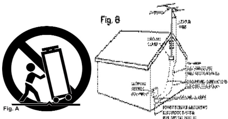
CART: A product and cart combination should be moved with care. Quick stops, excessive force, and uneven surfaces may cause the product and cart combination to overturn. See Figure A.
VENTILATION: Slots and openings in the cabinet are provided for ventilation and to ensure reliable operation of the product and to protect it from overheating, and these openings must not be blocked or covered. The openings should never be blocked by placing the product on a bed, sofa, rug, or other similar surface. This product should not be placed in a built-in installation such as a bookcase or rack unless proper ventilation is provided or the manufacturer's instructions have been adhered to.
POWER SOURCES: This product should be operated only from the type of power source indicated on the marking label. If you are not sure of the type of power supply to your home, consult your product dealer or local power company.
LOCATION: The appliance should be installed in a stable location.
NON-USE PERIODS: The power cord of the appliance should be unplugged from the outlet when left unused for a long period of time.
GROUNDING OR POLARIZATION:
-
If this product is equipped with a polarized alternating current line plug (a plug having one blade wider than the other), it will fit into the outlet only one way. This is a safety feature. If you are unable to insert the plug fully into the outlet, try reversing the plug. If the plug should still fail to fit, contact your electrician to replace your obsolete outlet. Do not defeat the safety purpose of the polarized plug.
-
If this product is equipped with a three-wire grounding type plug, a plug having a third (grounding) pin, it will only fit into a grounding type power outlet. This is a safety feature. If you are unable to insert the plug into the outlet, contact your electrician to replace your obsolete outlet. Do not defeat the safety purpose of the grounding type plug.
POWER-CORD PROTECTION: Power-supply cords should be routed so that they are not likely to be walked on or pinched by items placed upon or against them, paying particular attention to cords at plugs, convenience receptacles, and the point where they exit from the product.
OUTDOOR ANTENNA GROUNDING: If an outside antenna or cable system is connected to the product, be sure the antenna or cable system is grounded so as to provide some protection against voltage surges and built-up static charges. Article 810 of the National Electrical Code, ANSI/NFPA 70, provides information with
regard to proper grounding of the mast and supporting structure, grounding of the lead-in wire to an antenna discharge unit, size of grounding conductors, location of antenna-discharge unit, connection to grounding electrodes, and requirements for the grounding electrode. See Figure B.
LIGHTENING: For added protection for this product during a lightening storm, or when it is left unattended and unused for long periods of time, unplug it from the wall outlet and disconnect the antenna or cable system. This will prevent damage to the product due to lightening and power-line surges.
POWER LINES: An outside antenna system should not be located in the vicinity of overhead power lines or other electric light or power circuits, or where it can fall into such power lines or circuits. When installing an outside antenna system, extreme care should be taken to keep from touching such power lines or circuits as contact with them might be fatal.
OVERLOADING: Do not overload wall outlets, extension cords, or integral convenience receptacles as this can result in a risk of fire or electric shock.
OBJECT AND LIQUID ENTRY: Never push objects of any kind into this product through openings as they may touch dangerous voltage points or short-out parts that could result in a fire or electric shock. Never spill liquid of any kind on the product.
SERVICING: Do not attempt to service this product yourself as opening or removing covers may expose you to dangerous voltage or other hazards. Refer all servicing to qualified service personnel.
DAMAGE REQUIRING SERVICE: Unplug this product from the wall outlet and refer servicing to qualified service personnel under the following conditions:
- When the power-supply cord or plug is damaged.
- If liquid has been spilled, or objects have fallen into the product.
- If the product has been exposed to rain or water.
- If the product does not operate normally by following the operating instructions. Adjust only those controls that are covered by the operating instructions as an improper adjustment of other controls may result in damage and will often require extensive work by a qualified technician to restore the product to its normal operation.
-
If the product has been dropped or damaged in any way.
-
When the product exhibits a distinct change in performance, this indicates a need for service.
REPLACEMENT PARTS: When replacement parts are required, be sure the service technician has used replacement parts specified by the manufacturer or have the same characteristics as the original part. Unauthorized substitutions may result in fire, electric shock, or other hazards.
SAFETY CHECK: Upon completion of any service or repairs to this product, ask the service technician to perform safety checks to determine that the product is in proper operating condition.
WALL OR CEILING MOUNTING: The product should not be mounted to a wall or ceiling.
HEAT: The product should be situated away from heat sources such as radiators, heat registers, stoves, or other products (including amplifiers) that produce heat.

Rd
Fou

Rd
PDM-02
Fou
#

#
INTRODUCTION:
Congratulations on purchasing a Gemini PDM series 19"5U, 4 channel, rack mounted audio mixer. This state of the art mixer is backed by a 3 year warranty, excluding the cross fader. The cross fader is backed by a separate 90 day warranty. Prior to use, we suggest that you carefully read all the instructions.
FEATURES:
- 5U, 19" rack mounted mixer
- 4 stereo channels
- 7 lines, 3 Mic, 2 phono/line convertible RCA inputs
- Master, record, booth, & zone RCA outputs
- 1/4" balanced master output
- 2 x 1/4" Mic inputs
- Dual 10 band graphic EQ with on/off switch & blue LED indicator
- Rotary zone, booth, & cue volume controls
- Stereo/mono switch
- Assignable cross fader
- Removable, user replaceable Rail Glide cross fader
- Push button cue section per channel with green LED indicator
- CUE/PGM fader control allowing cue mix
- XLR-1/4" combo Mic input
- 2 band rotary Mic EQ & volume controls
- Talk over feature
- BNC lamp port
- 1/4" headphone jack
NOTE: ABOVE FEATURES INCLUDED IN EACH MODEL IN THE PDM SERIES.
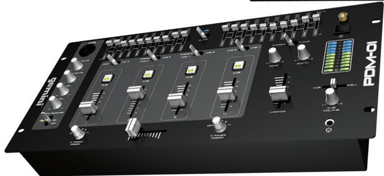
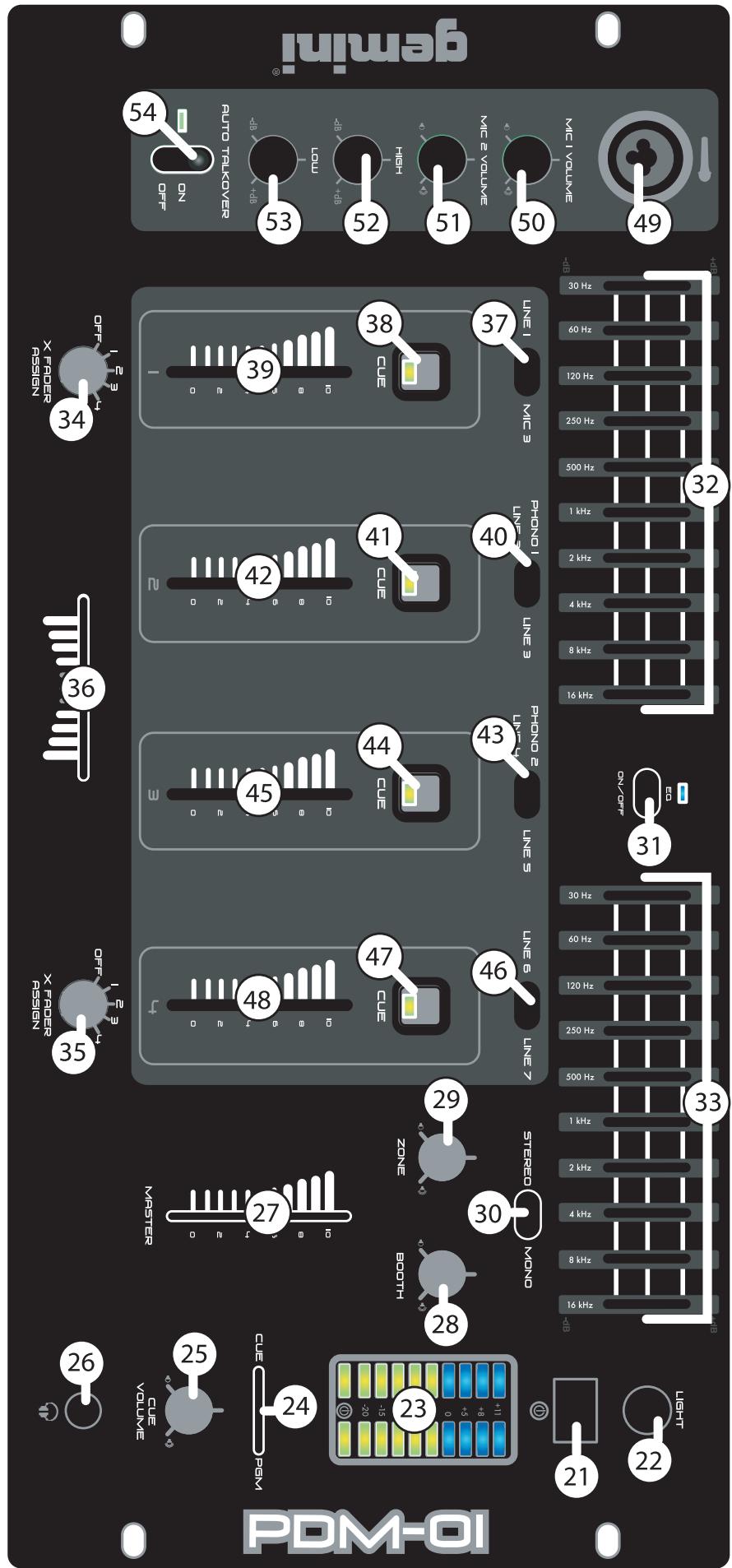
PDM-01 FACE:
- Master volume line fader control
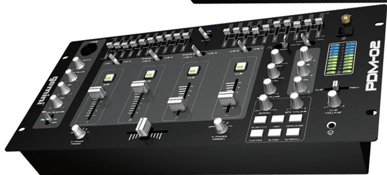
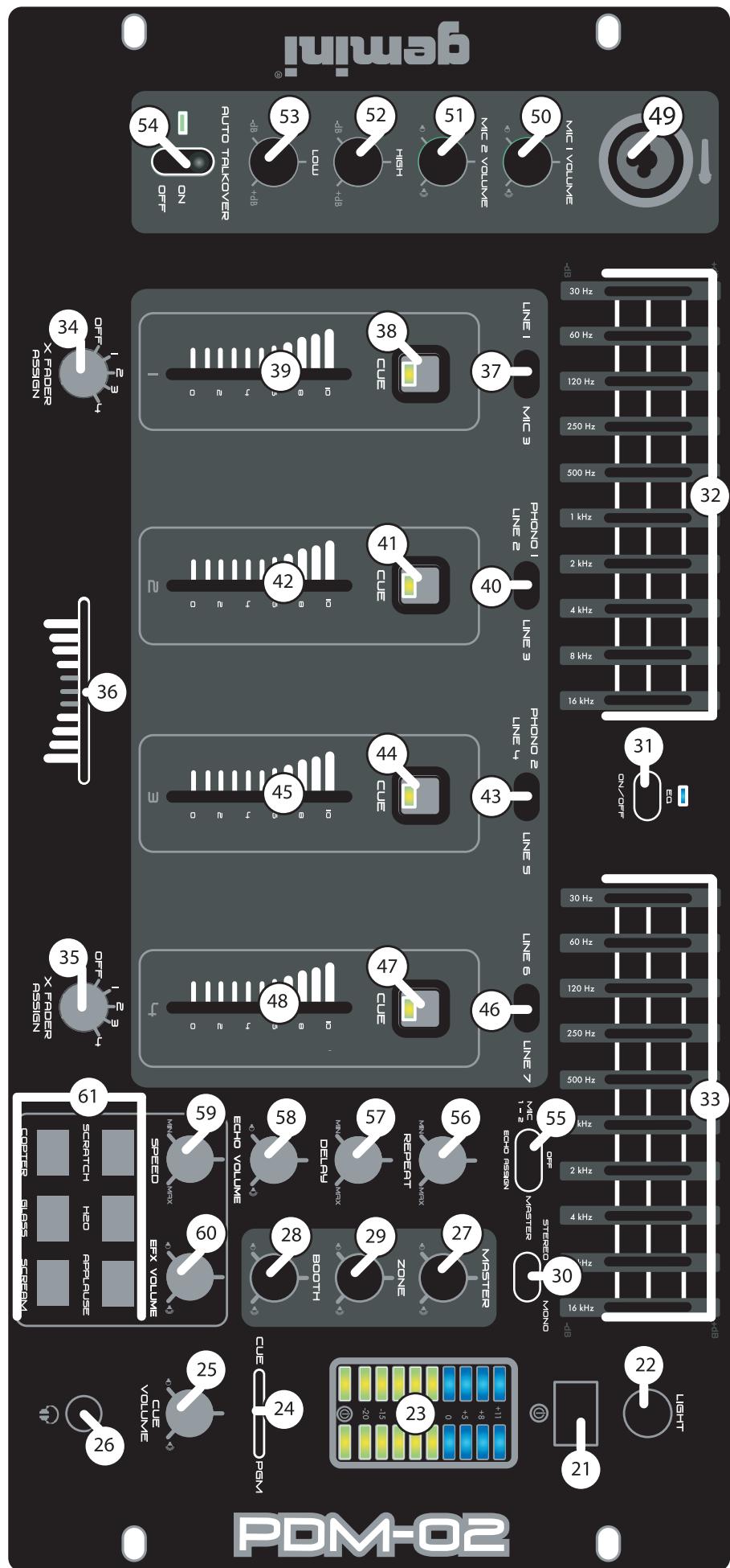
PDM-02 FACE:
- 6 digital samples with volume, & speed rotary controls
- Rotary master volume control
- Master/Mic assignable echo effect switch with repeat & delay controls
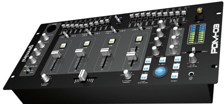
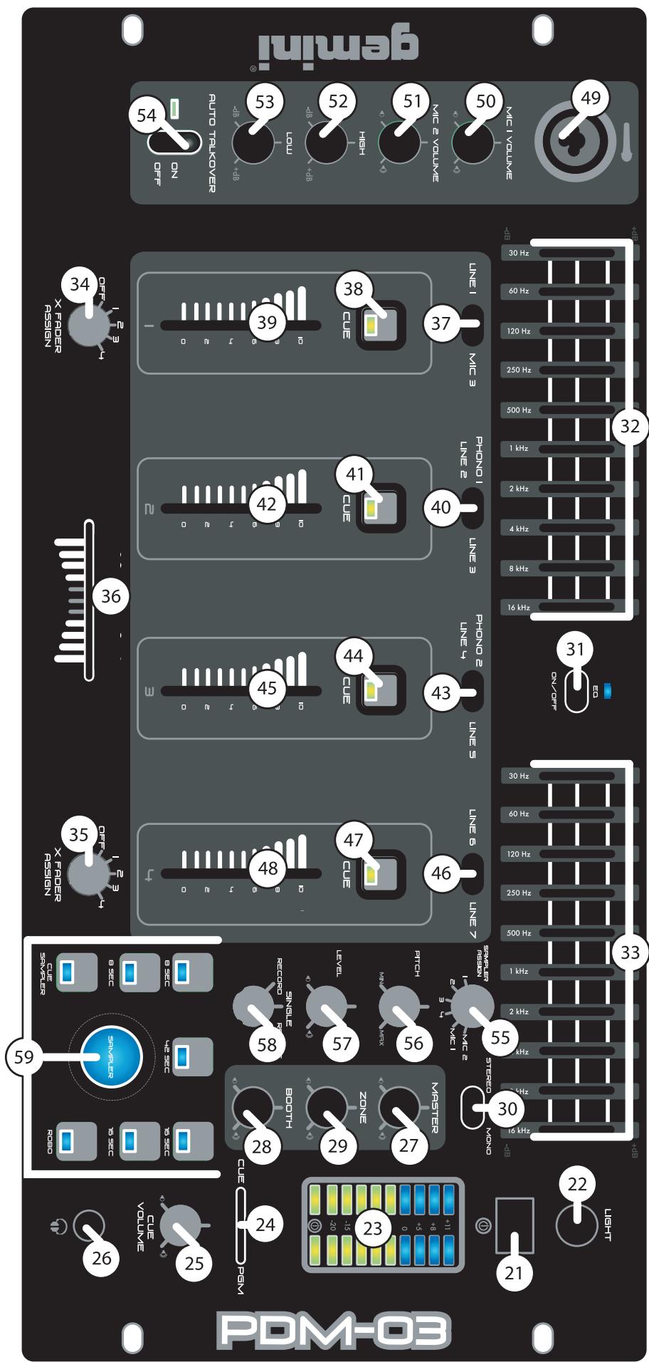
PDM-03 FACE:
- 96 second digital sampler comprised of 5 memory banks with soft touch backlit sample buttons
-
Rotary assignable channel control for sample recording
-
Sample parameter control with rotary level, pitch bend, record/single/repeat controls
-
Push button RoboPlay & cue sampler
- Rotary master volume control
PRECAUTIONS:
- All operating instructions should be read before using this equipment.
- To reduce the risk of electrical shock, do not open the unit. Please refer servicing to a qualified service technician.
IN THE USA ~ IF YOU EXPERIENCE PROBLEMS WITH THIS UNIT CALL GEMINI CUSTOMER SERVICE AT: 1 (732) 738-9003. DO NOT ATTEMPT TO RETURN THIS EQUIPMENT TO YOUR DEALER.
- Do not expose this unit to direct sunlight or to a heat source such as a radiator or stove.
- This unit should be cleaned only with a damp cloth. Avoid solvents or other cleaning detergents.
- When moving this equipment, it should be placed in its original carton and packaging. This will reduce the risk of damage during transit.
- DO NOT EXPOSE THIS UNIT TO RAIN OR MOISTURE.
- DO NOT USE ANY SPRAY CLEANER OR LUBRICANT ON ANY CONTROLS OR SWITCHES.
CONNECTIONS:
- Before plugging the power cord in, make sure that the VOLTAGE SELECTOR (1) switch is set to the correct voltage.
- Located on the rear panel is the 115 V/230 V PLUG (2). Before plugging the power cord in, make sure the POWER SWITCH (21) located on the face panel is turned OFF.
-
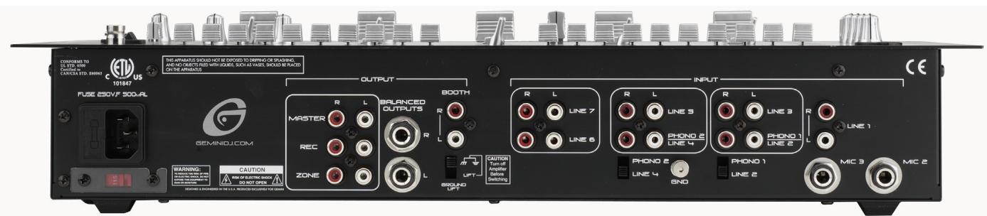
The PDM mixers have 5 sets of outputs:
-
The MASTER (3) output jacks connects to the main amplifier with RCA cables.
-
Alternatively, the BALANCED MASTER (6) output jacks also connects the mixer to the main amplifier using standard cables with 1/4" TRS connectors. We recommend using balanced cables if the distance to your amp is 10 feet or more.
- The BOOTH (7) output jacks allow the connection of an additional amplifier with RCA cables.
- The ZONE (5) output jacks allow the connection of an additional amplifier with RCA cables.
-
The REC (4) output jacks can be used to connect the mixer to the record input of your recording unit, thus enabling you to record your mix.
-
Located on the rear panel are 2 PHONO (PH) /LINE (LN) convertible RCA inputs (12, 16), & 5 LINE RCA INPUTS (10, 9, 13, 17, 18). The convertible RCA inputs for CH 2 (16) & CH 3 (12) allow PH and LN level equipment to be connected to the mixer. To adjust the CONVERTER(s) (11, 15), just flip the switch UP to operate PH 1 or PH 2. Flip the switch DOWN to operate through LN 2 or LN 4. The PH INPUTS only accept turntables with a magnetic cartridge. When using (a) turntable(s), you will need to ground the RCA cable(s) by screwing in the grounding fork(s) to the GROUNDING SCREW (14) located in the back panel of the PDM mixers. This is located in between the CONVERTER SWITCHES (11, 15). The stereo LN INPUTS only accept line level inputs such as a CD, DAT, MiniDisc, etc.
NOTE: WHEN USING TURNTABLES, NOT ATTACHING A GROUND MAY CAUSE A SYSTEM "HUM."
- Headphones may be plugged into the face-plate located 1/4" HEADPHONE JACK (26).
- The MIC 1 (49) input (located on the face panel) is a combination XLR & 1/4" connector. The MIC 2 (20) & MIC 3 (19) inputs (in the rear panel) accept only 1/4" connectors. The mic inputs accept balanced & unbalanced connections.
- The BNC LAMP PORT (22) (located on the face panel, above the POWER SWITCH (21)) is used to plug in a 12 V BNC goose neck lamp such as the Gemini GNL-700.
OPERATING INSTRUCTIONS:
- Once all of your connections have been made in the rear panel, turn ON the mixer by pressing the POWER SWITCH (21). Once turned ON, the POWER BAR LED, containing the power symbol located in the VU METER (23), will be illuminated. Turn OFF the mixer when not in use by pressing the POWER SWITCH (21) to OFF. When the PDM mixer is turned OFF the POWER BAR LED will not be illuminated.
- CHANNEL (CH) 1: To bring this channel into program mix (PGM), you must first decide which LN will be in use. Use the LN SWITCH (37) to toggle from LN 1 (18) to MIC 3 (19) on this channel. Slowly raise the CH 1 SLIDE CONTROL (39) to a comfortable level, once you've selected the proper line.
- CH 2: To bring this channel into PGM, you must first decide which LN will be in use. Use the LN SWITCH (40) to toggle from PH 1/LN 2 (16) to LN 3 (17) on this channel. Slowly raise the CH 2 SLIDE CONTROL (42) to a comfortable level, once you've selected the proper line.
- CH 3: To bring this channel into PGM, you must first decide which LN will be in use. Use the LN SWITCH (43) to toggle from PN 2/LN 4 (12) to LN 5 (13) on this channel. Slowly raise the CH 3 SLIDE CONTROL (45) to a comfortable level, once you've selected the proper line.
- CH 4: To bring this channel into PGM, you must first decide which LN will be in use. Use the LN SWITCH (46) to toggle from LN 6 (10) to LN 7 (9) on this channel. Slowly raise the CH 4 SLIDE CONTROL (48) to a comfortable level, once you've selected the proper line.
- CUE: By connecting a set of headphones to the HEADPHONE (26) jack, you can monitor any or all channels. Press the CUE BUTTONS (38, 41, 44, 47) for CHs 1 through 4, respectively, to assign the CH(s) to be monitored. The respective CUE LED indicators will glow when in use. Use the rotary CUE VOLUME CONTROL (25) to adjust the CUE volume without changing the overall mix. By moving the CUE/PGM FADER CONTROL (24) to the LEFT you will be able to monitor the assigned CUE signal. Moving the CUE/PGM FADER CONTROL (24) to the MIDDLE allows CUE mix with PGM. Moving the CUE/PGM FADER CONTROL (24) to the RIGHT allows you to monitor PGM output.
- ASSIGN: There are 2 rotary controlled X FADER ASSIGN SWITCHES (34, 35), each having 5 settings OFF, 1, 2, 3, & 4. The LEFT (34) not
ASSIGN switch allows you to direct CH 1, 2, 3, or 4 through the LEFT side of the CROSS FADER (36). The RIGHT ASSIGN (35) switch allows you to direct CH 1, 2, 3, or 4 through the RIGHT side of the CROSS FADER (36). When the ASSIGN SWITCH(es) (34, 35) are at OFF, you will not have a CH assigned to the CROSS FADER (36). This allows you to control the PGM with the use of the respective CH SLIDE CONTROLS, thus layering the PGM with up to four CHs.
8. CROSS FADER SECTION: The CROSS FADER (36) allows you to mix from one source to another. The PDM mixers feature an assignable CROSS FADER (36). The rotary controlled ASSIGN SWITCHES (34, 35) allow you to select which channel will play through each side of the CROSS FADER (36). The CROSS FADER (36) in your unit is removable & if the need arises can be easily replaced. Your Gemini mixer comes with a RG- 45 (RAILGLIDE™) DUAL-RAIL CROSS FADER. RAIL GLIDE™ CROSS FADERS have internal dual stainless steel rails that allow the slider to ride smoothly and accurately from end to end. Also available is our RG-45 PRO (PROGLIDE™) CROSS FADER with a special curve designed for scratch mixing. Just purchase one from your Gemini dealer & follow the instructions:
REPLACEABLE CROSS FADER
- UNSCREW THE OUTSIDE FADER PLATE SCREWS (B).
-DO NOT TOUCH INSIDE SCREWS(C). - CAREFULLY REMOVE OLD CROSS FADER AND UNPLUG CABLE (D).
- PLUG IN THE NEW CROSS FADER INTO CABLE (D) AND PLACE BACK INTO MIXER.
- SCREW THE CROSS FADER TO MIXER WITH THE FADER PLATE SCREWS (B).
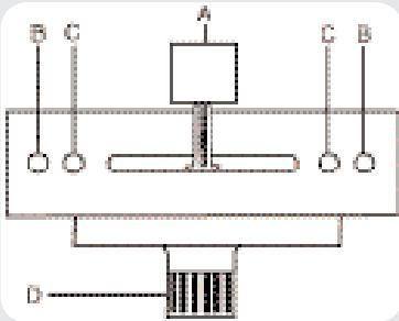
NOTE: DO NOT APPLY PRESSURE WHILE USING THE CROSSFADER. LIGHTLY GLIDE THE CROSSFADER BACK AND FORTH. PRESSING DOWN ON THE CONTROLS CAN BEND CONTACTS AND CAUSE A LOSS OF SOUND.
- EQUALIZER (EQ): These units feature dual 10 BAND GRAPHIC EQUALIZERS (32, 33) that will allow you to adjust the sound to fit any room. By adjusting any of the 10 EQ SLIDE CONTROLS (32, 33), you can cut or boost the tonal characteristics of the sound coming from PGM to the speaker(s) by ± 12 dB. To activate the dual 10 BAND GRAPHIC EQ, switch the EQ SWITCH (31) to ON, & the EQ LED will light up to indicate that the EQ has been engaged. To deactivate the dual 10 band graphic EQ, switch the EQ SWITCH (31) to OFF, & the EQ LED will turn OFF. When activated, the EQ (32, 33) controls the LEFT and RIGHT side of your stereo speakers. The PGM & EQ are controlled by the MASTER VOLUME (27). To balance the sound of the PGM playing through the MASTER VOLUME (27) on the LEFT & RIGHT side of your speakers you must mirror the EQ levels on the LEFT (32) & RIGHT (33) EQ controls.
NOTE: FOR OPTIMAL PERFORMANCE IN YOUR SOUND OUTPUT, HAVE YOUR SOUND SET TO STEREO NOT MONO. START WITH THE EQ LEVELS (32, 33) AT CENTER VALUE. THE EQ SLIDE CONTROLS (32, 33) SHOULD LOCK AT THIS POSITION. ADJUST YOUR MASTER VOLUME (27) CONTROL FROM MID TO LOW VOLUME RANGE. THEN ADJUST THE LEFT (32) OR RIGHT (33) EQ, ONE SLIDE CONTROL AT A TIME, TO A COMFORTABLE LEVEL. ONCE YOU ARE SATISFIED WITH THE SOUND OF ONE SIDE, MATCH THE EQ SETTINGS ON THE OTHER SIDE. ONCE YOU HAVE PASSED THE CENTER VALUE ON THE EQ (32, 33), THE MASTER OUTPUT, AS INDICATED IN THE VU METER (23), MAY EXPERIENCE A TONAL BOOST. PLEASE ADJUST THE MASTER VOLUME (27) TO A COMFORTABLE LEVEL SO YOU DO NOT OVERLOAD YOUR SYSTEM. CLIPPING WILL OCCUR WHEN YOU ARE OVERLOADING YOUR SYSTEM. LOWER THE MASTER VOLUME (27) OR ADJUST YOUR EQ (32, 33) SETTINGS SO THAT CLIPPING DOES NOT OCCUR. THEN YOU MAY RAISE THE MASTER VOLUME (27) TO A LEVEL WITH WHICH YOU ARE COMFORTABLE. - STEREO/MONO: You can convert your sound output from STEREO to MONO & vice versa by using the STEREO/MONO SWITCH (30). Switch to the LEFT to convert to STEREO. Switch RIGHT to convert to MONO.
- OUTPUT SELECTION CONTROL: Once you are comfortable with the sound level of your music you may adjust the decibel level of the PGM with the MASTER VOLUME (27) control. MASTER RCA & BALANCED MASTER OUTPUTS (3, 6) are controlled by the level of the MASTER VOLUME (27) control. You may adjust the volume of the ZONE (5) output with the ZONE (29) rotary control. You may adjust the volume of the BOOTH (7) output with the BOOTH (28) rotary control. The volume of your RECORD (4) output is controlled strictly by the CH SLIDE CONTROLS.
- MIC SECTION: Plug your main MIC into the MIC 1 combination XLR-1/4" input (49) located on the face panel. The rotary controls for HIGH (52) and LOW (53) allow you to adjust the tone of MIC 1 (49). The rotary MIC 1 VOLUME CONTROL (50), above the rotary MIC 2 VOLUME CONTROL (51), adjusts the decibel level of MIC 1 (49). You may
also plug a second & third MIC into the rear panel's MIC 2 (20) & MIC 3 (19) 1/4" jacks. The decibel level of MIC 2 (20) is controlled by the rotary MIC 2 VOLUME CONTROL (51). The decibel level of MIC 3 (19) is controlled by the CH 1 SLIDE CONTROL (39).
- TALKOVER: The purpose of the AUTO TALKOVER MODE is to allow the program playing to be attenuated so that the MIC may be heard above the music. The AUTO TALKOVER SWITCH (54) controls MIC 1 (49) and MIC 2 (20) with 3 settings:
- When the MIC/TALKOVER SWITCH (54) is in the BOTTOM position, MIC 1 (49), MIC 2 (20) & TALKOVER MODE are all OFF.
- When the MIC/TALKOVER SWITCH (54) is in the CENTER position, MIC 1 (49) & MIC 2 (20) are ON & TALKOVER MODE is OFF. The MIC ON LED indicator glows when MIC 1 (49) & MIC 2 (20) are ON.
- When the MIC/TALKOVER SWITCH (54) is in the TOP position, MIC 1 (49) & MIC 2 (20) are ON, TALKOVER MODE is ON, & the volume of all sources except MIC 1 (49) & MIC 2 (20) are lowered automatically by -16 dB, when speaking into the MIC(s).
- BNC LAMP PORT: The BNC LAMP PORT (22) connects a 12 V BNC goose neck lamp, such as the Gemini GNL-700 to the PDM mixer. The goose neck lamp will be powered by your mixer. To turn ON the goose neck lamp, you must first attach the goose neck lamp to the BNC LAMP PORT (22). Make sure the PDM mixer is OFF when connecting the 12 V BNC lamp. To connect the goose neck lamp, simply align the screw cap of the goose neck lamp to the locking nodules of the BNC LAMP PORT (22), push down, & twist the screw cap clockwise to lock the 12 V BNC goose neck lamp in place. Then turn ON your mixer. The goose neck lamp should light-up. To detach the goose neck lamp from the BNC LAMP PORT (22), first make sure your mixer is OFF. Turn OFF your mixer and the goose neck lamp will turn OFF. Unscrew the screw cap by twisting it counterclockwise, then pull up & remove the goose neck lamp.
- GROUND LIFT SWITCH: The GROUND LIFT SWITCH (8) is used to reduce background noise & hum when using multiple outlets to power audio equipment. The switch should be in the position that provides the least amount of noise or hum. If noise remains at the same level in both positions, the GROUND LIFT SWITCH (8) should be kept in the GND position.
NOTE: MAKE SURE THE MIXER AND/OR AMPLIFIER IS OFF BEFORE SWITCHING THE GROUND LIFT SWITCH TO PREVENT A TRANSIENT POP THAT MAY DAMAGE YOUR SYSTEM. - VU METER: The VU METER (23) indicates the decibel level of the MASTER RCA & MASTER BALANCED (3 & 6) outputs of the LEFT & RIGHT stereo levels.
PDM-02 ECHO/EFX:
ECHO SECTION:
An echo effect may be applied to the PGM, or MIC 1 (49) & MIC 2 (20) signals by switching the ECHO ASSIGN (55) switch from MIC 1-2 on the LEFT, to OFF in the MIDDLE, to MASTER on the RIGHT & vice versa. When using ECHO (55), you may adjust the effect of the ECHO (55) by using the rotary REPEAT (56), DELAY (57), and ECHO VOLUME (58) controls. To turn the ECHO ASSIGN (55) OFF or lower the ECHO VOLUME (58).
SOUND EFFECTS SECTION:
Six different sound effects (APPLAUSE, SCREAM, COPTER, SCRATCH, H_2O & GLASS) may be added to your mix by pressing the SOUND EFFECTS CONTROL BUTTONS (61). The volume of the effects can be adjusted using the rotary EFX VOLUME (60) located above the APPLAUSE effect button. The pitch of the effects can be increased or decreased using the rotary SPEED CONTROL (59) located above the SCRATCH effect button.
PDM-03 SAMPLER OPERATION:
MEMORY INFORMATION:
The PDM-03 is equipped with 5 MEMORY BANKS (59). The two banks marked 8 & 8 are 8 seconds in length, the two banks marked 16 & 16 are 16 seconds in length and the bank marked 48 is 48 seconds in length. These banks are separate & CANNOT be linked. You can store a different sample in each bank, but they must be recorded individually & must be played one at a time.
SAMPLE RECORDING:
- Select the sample source by switching to the appropriate channel with the rotary SAMPLER ASSIGN (55) control.
- The PDM-03 comes equipped with a rotary sampler PITCH CONTROL (56). To get a "perfect" sample, set the control to its CENTER position & record the sample. Raising or lowering the control during playback raises or lowers the pitch of the sample. The CENTER position retains the "normal" pitch.
HINT: YOU CAN RECORD A SAMPLE WITH THE PITCH CONTROL IN ANY POSITION. THAT POSITION SETTING WILL BECOME THE NORMAL PITCH. IF YOU START TO RECORD A SAMPLE WITH THE PITCH CONTROL SET AT "MINIMUM" THAT WILL BECOME YOUR NORMAL PITCH. BY INCREASING THE PITCH TO "MAXIMUM" DURING PLAYBACK, THE PITCH EFFECT WILL DOUBLE IN SPEED. RECORDING AT "MAXIMUM" AND LOWERING TO "MINIMUM" DURING PLAYBACK WILL DO EXACTLY THE OPPOSITE.
- Put the MODE SELECTOR (58) switch into the RECORD position.
- Listen to the channel to be recorded in CUE, by selecting the appropriate CUE button for this channel. When the track approaches the section to be sampled, press the proper MEMORY BANK (59) button where you want the sample to be stored.
- Then press the SAMPLER (59) button to start recording the sample. The Memory bank in use will have a blinking LED, if a battery is not in place or the battery is low (See BATTERY BACKUP section). The sample will be stored in this MEMORY BANK (59) & ready to play.
NOTE: TAPPING THE SAMPLER BUTTON BEGINS THE SAMPLING PROCESS (THE SAMPLER INDICATOR WILL "GLOW" BLUE DURING RECORDING). TAPPING THE SAMPLER BUTTON A SECOND TIME ENDS THE SAMPLE (THE SAMPLER INDICATOR WILL TURN OFF). IF YOU DO NOT TAP THE SAMPLER BUTTON A SECOND TIME, THE SAMPLING PROCESS STOPS AUTOMATICALLY AFTER 8, 16 OR 48 SECONDS DEPENDING ON WHICH MEMORY BANK WAS SELECTED.
CUE SAMPLER:
- To record in CUE, press the CUE SAMPLER button and then press the CUE button for the channel to be sampled. Be sure your CH slide controls are at zero so the sample does not play in PGM. Follow the SAMPLE RECORDING instructions to complete the process.
- To test the recorded sample before playing in PGM, press the CUE SAMPLER (59) button, placing the sampler in CUE. The blue CUE SAMPLER LED will illuminate while in use. Use the CUE controls to monitor this sample. Be sure your rotary SAMPLER LEVEL (57) is turned counter clockwise so that the sample is not played in PGM. Set your sampler to SINGLE or REPEAT, then press the SAMPLER button and the sample will begin playing in CUE. If you are satisfied with your sample, leave it stored in the MEMORY BANK (59). If not, please repeat the steps for SAMPLE RECORDING.
SAMPLE PLAYBACK:
- Set the MODE SELECTOR (58) switch to SINGLE or REPEAT.
- Select the desired sample by pressing the proper MEMORY BANK (59) button.
- Tapping the SAMPLER (59) button with the MODE SELECTOR (58) switch in the SINGLE position causes SAMPLER to play back one time (the SAMPLER INDICATOR will "glow" GREEN). Each push of the SAMPLER button restarts the sample from the beginning. Rapid pressing of the SAMPLER button will cause a stuttering effect. Once the sample has started playback & the SAMPLER button is not pushed a second time, the SAMPLE will SINGLE to the end & stop. This Sample will play through completely regardless of switching the MEMORY BANK. Switching the MEMORY BANK and pressing the SAMPLER button while the sample is in play will repeat the sample previously selected until it has completed its play cycle.
- To play a new sample from another MEMORY BANK the old sample
must be stopped. Choose the MEMORY BANK to play. Then press SAMLPLER to begin the new Sample playback.
- Tapping the SAMPLER (59) button with the MODE SELECTOR (58) switch in the REPEAT position causes the SAMPLE to loop play continuously. In REPEAT mode, the SAMPLER button acts an ON/OFF switch. The first push starts the sample, the second push stops it.
- The S AMPLER LEVEL (57) controls the decibel level of the sample. This feature allows you to adjust the volume of the sample to play over or under PGM.
ROBO PLAY:
- With the ROBO (59) button OFF the blue LED is OFF & the MODE SELECTOR (58) switch in either the SINGLE or REPEAT mode, pressing the SAMPLER (59) button will cause the sample to play along with the selected source.
- When the ROBO (59) button is ON, the BLUE LED is on & starting the sampler mutes the selected source. When the sample ends, the source automatically turns back on.
BATTERY BACKUP:
- BATTERY BACKUP: The PDM-03 is equipped with battery backup to retain samples. To activate this feature, a 9 V battery (not included) should be connected to the BATTERY HOLDER (60) located on the rear panel. This enables the storage of samples in memory. When the unit is unplugged, the battery backup retains the samples for future use.
NOTE: IF THE UNIT IS UNPLUGGED WITH NO BATTERY ATTACHED, ALL SAMPLES WILL BE LOST. - LOW BATTERY INDICATOR: When the selected memory bank LED blinks, this will indicate that there is a low battery or no battery in the PDM-03. The LED blinks a warning if no battery is connected to the PDM-03. When changing or placing the battery into the PDM-03, make sure the unit is plugged in and the power is ON. Failure to adhere to this will result in lost memory and "vanished" samples.
SPECIFICATIONS:
INPUTS:
Phono: .3 mV, 47 KOhm
Line: 150 mV, 27 KOhm
MIC 1, 2, & 3: 1.5 mV, 2 K Ohm Balanced
Bass: 12dB
High: ± 12dB
OUTPUTS:
Amp/Booth: 0 dB 1 V, 400 Ohm
Max: 20 V Peak-to-Peak
Rec. 150 mV, 5 KOhm
Zone. 0 dB 1 V 400 Ohm
Balanced. 6 dB 2 V 400 Ohm
GENERAL:
Frequency Response: 20 Hz - 20 KHz +/- 2 dB
Distortion: 0.02%
S/N Ratio: Better Than 80 dB
Talkover Attenuation: -16 dB
Headphone Impedance: 16 Ohm
Power Source: 115/230 V, 60/50 Hz, 20 W
Unit Dimensions: W 19" x H 4" x D 9.1"
(482.6 x 100.6 x 231.2 mm)
Weight: 10.34 lbs (4.7 kg)
SPECIFICATIONS SUBJECT TO CHANGE WITHOUT NOTIFICATION FOR IMPROVEMENT.
EINFUHRUNG:
Zone. 0 dB 1 V 400 Ohms
Attenuation Talkover: -16 dB
Impedance casque: 16 Ohms
Alimentation: 115/230 V, 60/50 Hz, 20 W
IN THE USA: IF YOU EXPERIENCE PROBLEMS WITH THIS UNIT, CALL 1-732-738-9003 FOR GEMINI CUSTOMER SERVICE. DO NOT ATTEMPT TO RETURN THIS EQUIPMENT TO YOUR DEALER.
Parts of the design of this product may be protected by worldwide patents. Information in this manual is subject to change without notice and does not represent a commitment on the part of the vendor. Gemini Sound Products Corp. shall not be liable for any loss or damage whatsoever arising from the use of information or any error contained in this manual. No part of this manual may be reproduced, stored in a retrieval system or transmitted, in any form or by any means, electronic, electrical, mechanical, optical, chemical, including photocopying and recording, for any purpose without the express written permission of Gemini Sound Products Corp. It is recommended that all maintenance and service on this product is performed by Gemini Sound Products Corp. or its authorized agents. Gemini Sound Products Corp. will not accept liability for loss or damage caused by maintenance or repair performed by unauthorized personnel.

Worldwide Headquarters • 120 Clover Place, Edison, NJ 08837 • USA Tel: (732) 738-9003 • Fax: (732) 738-9006
- PLEASE READ BEFORE USING APPLIANCE, IMPORTANT WARNING & SAFETY INSTRUCTIONS!
- CAUTION
- GROUNDING OR POLARIZATION:
- #
- INTRODUCTION:
- FEATURES:
- PDM-01 FACE:
- PDM-02 FACE:
- PDM-03 FACE:
- PRECAUTIONS:
- CONNECTIONS:
- OPERATING INSTRUCTIONS:
- REPLACEABLE CROSS FADER
- PDM-02 ECHO/EFX:
- ECHO SECTION:
- SOUND EFFECTS SECTION:
- PDM-03 SAMPLER OPERATION:
- MEMORY INFORMATION:
- SAMPLE RECORDING:
- CUE SAMPLER:
- SAMPLE PLAYBACK:
- ROBO PLAY:
- BATTERY BACKUP:
- SPECIFICATIONS:
- INPUTS:
- OUTPUTS:
- GENERAL:
- EINFUHRUNG:
- Worldwide Headquarters • 120 Clover Place, Edison, NJ 08837 • USA Tel: (732) 738-9003 • Fax: (732) 738-9006
Brand : GEMINI
Model : PDM-01
Category : Mixer