PHASE22 - Audio Interface TERRATEC - Free user manual and instructions
Find the device manual for free PHASE22 TERRATEC in PDF.
User questions about PHASE22 TERRATEC
0 question about this device. Answer the ones you know or ask your own.
Ask a new question about this device
Download the instructions for your Audio Interface in PDF format for free! Find your manual PHASE22 - TERRATEC and take your electronic device back in hand. On this page are published all the documents necessary for the use of your device. PHASE22 by TERRATEC.
USER MANUAL PHASE22 TERRATEC
24 Bit/96 kHz Recording Interface
TERRATEC PRODUCER/PHASE 22
English Manual
Version 1.0, last revised: October 2003
CE Declaration
We:
TerraTec Electronic GmbH, Herrenpfad 38, D-41334 Nettetal, Germany
hereby declare that the product:
PHASE 22,
to which this declaration refers is in compliance with the following standards or standardizing documents:
EN 50013, EN 50022
The following are the stipulated operating and environmental conditions for said compliance:
residential, business and commercial environments and small-company environments.
This declaration is based on:
Test report(s) of the EMC testing laboratory
H. CCC
The information in this document is subject to change without notice and shall not be deemed as a warranty by the seller. No warranties, express or implied, are made with regard to the quality, suitability or accuracy of this document. The manufacturer reserves the right to change the contents of this document and/or the associated products at any time without the provision of prior notice to specific persons or organizations. The manufacturer shall not be held liable for damages of any kind arising from the use, or the inability to use this product or its documentation, even if the possibility of such damage is known. The information in this document is subject to copyright. All rights are reserved. No part of this manual may be reproduced or transmitted in any form or for any purpose without the express written permission of the copyright holders. Product and brand names contained in this document are used for identification purposes only. All registered trademarks, product designations or brand names used in this document are the registered property of their respective owners.
©TerraTec® Electronic GmbH, 1994-2003. All rights reserved (13.10.03).
Contents
Welcome! 5
From unpacking to installation 7
Scope of delivery 7
The setup - Short and simple for busy professionals. 8
Notes for Windows users 8
Notes for Macintosh users 9
Installation of the PHASE PCI card - step by step 10
Installing the drivers and the Control Panel 11
Widows 98 SE installation 11
Windows ME installation 12
Windows 2000 installation. 13
Windows XP installation 17
Driver installation for Macintosh OS 10.x (OS X) 20
The connections of the PHASE 22 System 21
Analog outputs 22
Analog inputs 23
Digital interface (S/PDIF, RAW, AC3) 24
MIDI interface 25
The drivers (Windows operating system). 26
The Wave driver 26
The ASIO driver 26
The GSIF driver 27
The MIDI driver 27
In detail - special properties of the drivers 28
32-bit data transfer 28
DirectSound & WDM 29
WDM sample rate (SR) interpolation 29
WDM kernel streaming 29
The MAC OS X drivers 29
The Control Panel 30
How does the Control Panel work? 31
Analog In 31
Wave Record Select 31
Analog output 31
MasterClock. 32
DIGITAL OUT 32
Channel Status 33
ASIO (Windows) 33
The ASIO buffer size (Windows) 34
Card(s) used for ASIO - cascaded PHASE systems only. 34
Colors 35
Cascading and internal synchronization 36
Sync-In/Sync-Out 36
The PHASE Control Panel 37
Tips, tricks & things worth knowing 38
Dolby AC3 and DTS 38
Always with the beat - digital synchronization 38
About IRQs and other interrupts 39
Technical data 43
System requirements/recommendation 44
Safety note
Please switch off all analog equipment before connecting or disconnecting it. This will help you avoid electric shocks (albeit weak ones), and will prevent damage to your speakers and hearing resulting from sudden level spikes. For digital devices, be sure to at least lower the volume on your playback equipment.

Welcome!
We are pleased that you have chosen a TerraTec Producer Audio System for your musical endeavors and would like to congratulate you on your decision. With the PHASE 22 System, you've purchased a sophisticated product representing the state of the art of studio technology - and we're convinced this innovative development will prove extremely useful to you in the coming years and, above all, provide you with a great deal of entertainment.
We hope that this brochure is helpful to you while using the product. It is designed to illustrate technical relationships based on practical examples from the studio environment. However, it is designed not only for beginners, but also for those more advanced in this complex matter: Ambitious professionals, too, will surely learn something new here and there.
We hope you find this manual both informative and entertaining to read, and hope you find lots of pleasure in the PHASE 22 System.
Sincerely, Your TerraTec Producer Team
PHASE 22
24 Bit/96 kHz Recording Interface

The widest variety of connecting equipment. The PHASE 22 system is equipped with a wide range of connection options.
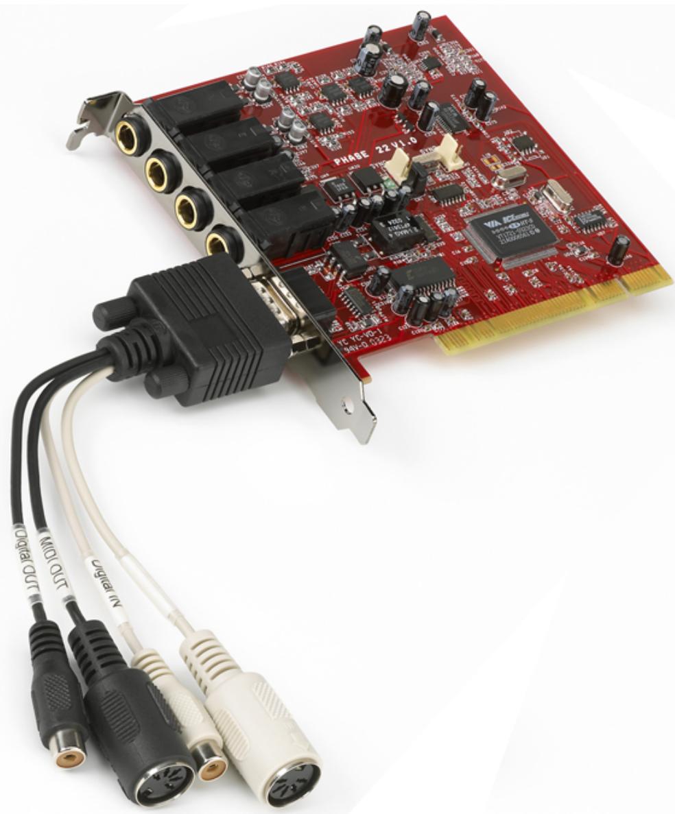
With two balanced inputs and outputs each, 1/4 jack, low-latency MIDI interface and coaxial digital I/O, the PHASE 22 audio system provides adequate connections in all directions on the PCI card and its breakout cable. The finest convertor elements and a wellthought-out board design allow crystal-clear recording and equally high-quality reproduction.
For everything you need to know about connections, see page 21
Nerve center – the software. As you know, a professional audio system is no sound card for gamers, but the heart of your day-to-day studio work with your PC. And despite the extensive routing options, the PHASE Control Panel always provides you with a clear overview and - depending on the complexity of your switching needs - remains transparent and intuitive.
For everything you need to know about the PHASE Control Panel, see 念 page 30.
The drivers provided for the PHASE 22 audio system, too, leave nothing to be desired. A highly developed software architecture guarantees problem-free use with all modern Windows and Apple operating systems.
The ASIO drivers - thoroughly proven throughout years of application and often used as a reference - allow the lowest possible latency between the software-based sound generation and audio output.
For the details on driver use, please turn to page 26.
From unpacking to installation
Before installing the PCI card into your computer and running cables to the PHASE 22 system, take note of any special points pertaining to the configuration of your computer. Also refer to the manual of your computer and other studio peripheral devices for their settings.
Please observe the following instructions to ensure a trouble-free installation. If you still have difficulties, please review carefully the relevant chapter in this manual.
Our service helpline is also available to assist you. For the phone number and current operating hours, please check the support area of the TerraTec webpage at: www.terratec.com.
Scope of delivery
Start by making sure that the contents of the package are complete.
The PHASE 22 System package should contain the following items:
1PCI card
1 multi-connector cable with digital I/O and MIDI I/O
1 EWS connect sync cable
1 PHASE driver CD
1 customer service card
1 registration card with the serial number
1 user guide (the one you are reading at the moment)
1 Besonic Premium Account
Please return the enclosed registration card to us at the earliest possible opportunity, or register online at www.terratec.net/register.htm. This is important for support and hotline services.
The setup – Short and simple for busy professionals
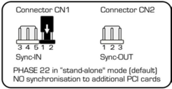
Before installing the PCI card, please check the Sync-In and Sync-Out connections (EWS® Connect) on the PCI card. If you do not have any other TerraTec PCI systems with EWS Connect connections in your computer, the following applies:
Sync-In (CN1) - the jumper must be positioned at 1-2;
○ Sync Out (CN2) - this connection remains free.
The EWS Connect connection
If you have additional TerraTec PCI systems with EWS-Connect connections in your computer and you would like to synchronize them, please see the chapter "Cascading and internal synchronization" starting on page 36.
The PHASE 22 Audio Interface is a PCI card with busmastering support. Please choose a slot that is as far away from the graphics card(s) and
SCSI/RAID controllers as possible - usually as close to the "bottom" as possible in most installations. Also be sure to leave room for the multi-connector cable and further cables connected to it.
You will need one (1) IRQ. Installing multiple audio systems of the TerraTec family is no problem - all PCI cards will run in IRQ-sharing mode. (For more information on cascading the products see page 36.)
The driver installation follows the established defaults set by the operating system manufacturers. You can find the drivers on the accompanying CD-ROM or on the Internet at www.terratec.com in the download area.
Notes for Windows users
The drivers have not been certified by Microsoft. You will receive a warning to this effect in Windows 2000 and XP, which you can safely ignore. You can continue the installation without concern.
■ After installing the drivers, open the Device Manager and check for yellow exclamation marks. If you find any, you can usually solve the problem by repeating the installation according to the instructions. A FAQ (Frequently Asked Questions) for initial problem-solving can be found on the product CD and on the Internet at www.terratec.com.
After the drivers have been installed, install the software. You can start the installation using the autostart function of the CD, for example. The PHASE 22 Control Panel must be installed. Full functionality is not provided using the standard Windows Mixer.
- The WDM audio drivers can be selected in the applications as usual. ASIO drivers are available in compatible programs; WDM kernel streaming is "not visible" (in other words, it is always available for applications needing it and cannot be selected manually). The respective buffer sizes can be configured in the Phase Control Panel (not to be confused with the Windows Control Panel).
Notes for Macintosh users
The PHASE 22 system is shipped with driver support for MAC OS 10 (OS X). In the OS10 version, we recommend the Apple operating system update called "Jaguar" (current version 10.2.6). A version update, which can be obtained for an extra charge, contains some improvements specially geared towards audio applications.
The audio and MIDI connection using OS 10(X) is built exclusively on the OS10 core audio/MIDI concept.
Installation of the PHASE PCI card - step by step
- Switch off your PC and all connected peripheral devices such as your printer and monitor. Leave the AC power cable connected for the time being, so that your computer is still grounded.
- Touch the metal chassis at the rear of the PC to ground and to discharge static. Now unplug the cord from the AC socket.
Remove the housing cover from your computer or open it. - Select a free PCI expansion slot that if possible does not share an IRQ with any other slot, if necessary remove the screw that retains the slot cover and remove the cover. Should it be necessary to break a cover out of the case, use flat-nose pliers and take care to avoid injury.
To ensure the optimal function of your system, look for an expansion slot that is not immediately next to an already-installed card. Some cards, such as video or SCSI/RAID adapters, can send out signals which can interfere with the sound card. We also recommend a slot as close to the bottom of the computer as possible, as you can / must connect several cables directly to the card itself. Due to certain laws of physics that apply on this planet, it is very likely that they will dangle downward, possibly covering any cards and their connectors installed below. And last but not least: Please read the IRQ Tutorial on page 39. - Carefully remove the PCI card from its packaging. To do so, place one hand on a metal part of the computer case while picking the card up by the edges. This will ensure that your body is completely discharged (no joke) via your computer without affecting the card. Please do not touch the components on the board.
Align the audio card so that the strip with the golden connector pins is located exactly over the PCI slot. - Insert the card into the slot. You might have to press the card firmly into the slot to make good contact. Take care to ensure that the contacts are exactly in line. If they are not, you could do damage to the audio card or your computer's motherboard. It should not be necessary to use force.
- Fasten the card in place using the screw you removed earlier from the slot cover (if there was one).
- Switch on and boot the computer to continue with the driver installation.
Installing the drivers and the Control Panel
The PHASE 22 system is shipped with drivers for the Windows 98SE, Windows ME, Windows 2000, Windows XP and MAC OS10 x operating systems. Windows 95/98/NT 4 as well as MAC OS9.x are not supported. You should therefore determine which operating system you are using before installing the card. For information on your Windows operating system and its version number, please check the "System" dialog in the Windows Control Panel.
In the following driver installation descriptions, <CD> stands for the drive letter of the CD-ROM drive containing the PHASE driver CD.
Widows 98 SE installation
- Boot your computer after installing the PHASE 22 PCI card.
- During the bootup process, the Windows hardware wizard will identify the new hardware as a "PCI Multimedia Audio Device". Confirm by clicking "Next".
- The hardware wizard will ask you how you would like to continue. Select the "Search for the best driver for my device (Recommended)" item and confirm with "Next".
- Check the "Specify a location" box and enter the path to the driver on the CD.
: \PHASE 22\Driver\PC\vX.XX (vX.XX stands for the driver version). Alternatively, you can also select the path to the best driver of your PHASE 22 PCI system using the mouse by clicking "Browse...". Confirm by clicking "Next". - In the last window, the hardware wizard will report that the driver software has been installed successfully. Close the wizard by clicking "Finish".
If Windows requests a second driver file, please refer to the aforementioned directory on the PHASE CD-ROM. It is also possible (e.g. if this is the first sound card installation in your system) that some additional Windows extensions have to be installed. Please have your Windows CD ready for this purpose.
If contrary to all expectations a request should appear for you to perform some action and you are not sure about it, then pressing the Enter key is generally a safe action.
After a successful driver installation, you should verify that your Windows 98SE system is functioning properly. The Device Manager presents an overview of hardware components installed and recognized on your computer. The Device Manager can be found in the Control Panel under "System."
After successful driver installation, the PHASE 22 Control Panel can be installed easily using the autorun option (
Windows ME installation
- Boot your computer after installing the PHASE 22 PCI card.
- During the boot, the Windows hardware wizard will identify the new hardware as a "PCI Multimedia Audio Device". Select here "Specify the location of the driver (Advanced)" and confirm with "Next".
- Activate the checkbox "Specify a location:", enter the path
:\PHASE 22\Driver\PC\vx.xx (vX.XX stands for the driver version). Confirm by clicking "Next". Alternatively, you can change to the respective directory by clicking on "Browse...". - The hardware wizard will now search for the AudioSystem PHASE 22 driver and will display the location of the driver. Confirm by clicking "Next".
- In the final window, the hardware wizard will report that the driver software has been installed successfully. Close the wizard by clicking "Finish".
If Windows requests a second driver file, please refer to the aforementioned directory on the PHASE CD-ROM. It is also possible (e.g. if this is the first sound card installation in your system) that some additional Windows extensions have to be installed. Please have your Windows CD ready for this purpose.
If contrary to all expectations a request should appear for you to perform some action and you are not sure about it, then pressing the Enter key is generally a safe action.
After a successful driver installation, you should verify the correct condition of your Windows ME system. The Device Manager presents an overview of installed and recognized hardware components of your computer. The Device Manager can be found on the "Control Panel" under "System" > "Hardware". Then click the "Device Manager" button.
After successful driver installation, the PHASE 22 Control Panel can be installed easily using the autorun option (
Windows 2000 installation
- Boot your computer after installing the PHASE 22 PCI card.
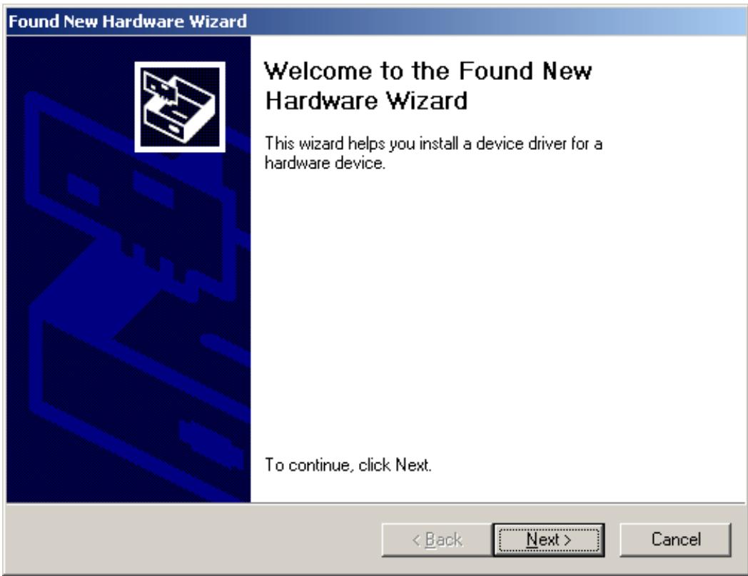
- During the boot, the Windows hardware wizard will identify the new hardware as a "Multimedia Audio Controller". Confirm by clicking "Next".
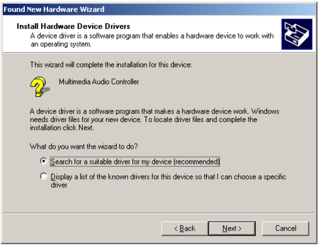
- Mark the "Search for a suitable driver for my device (recommended)" checkbox and insert the PHASE CD if you have not done so already. Subsequently confirm with "Next".
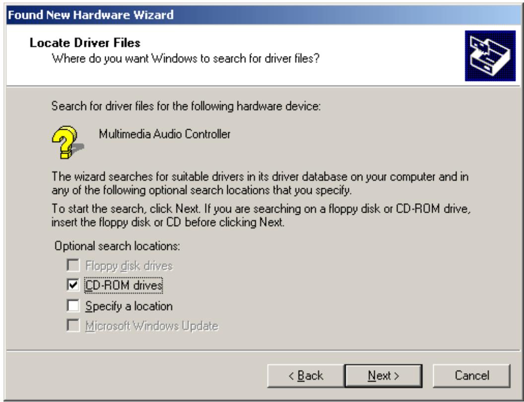
- The hardware wizard will now inform you that it will search for drivers for a "Multimedia Audio Controller". Activate the checkbox "CD-ROM drives" and confirm with "Next."
-
The hardware wizard will now indicate that it has found a suitable driver for the "Multimedia Audio Controller" on the CD-ROM (
:PHASE 22\Driver\PC\vX.XX). Click "Next" to start the installation. -
The following dialog box will now appear as the installation is continued:

This is no cause for alarm. Click "Yes" to continue. The installation will now be executed.
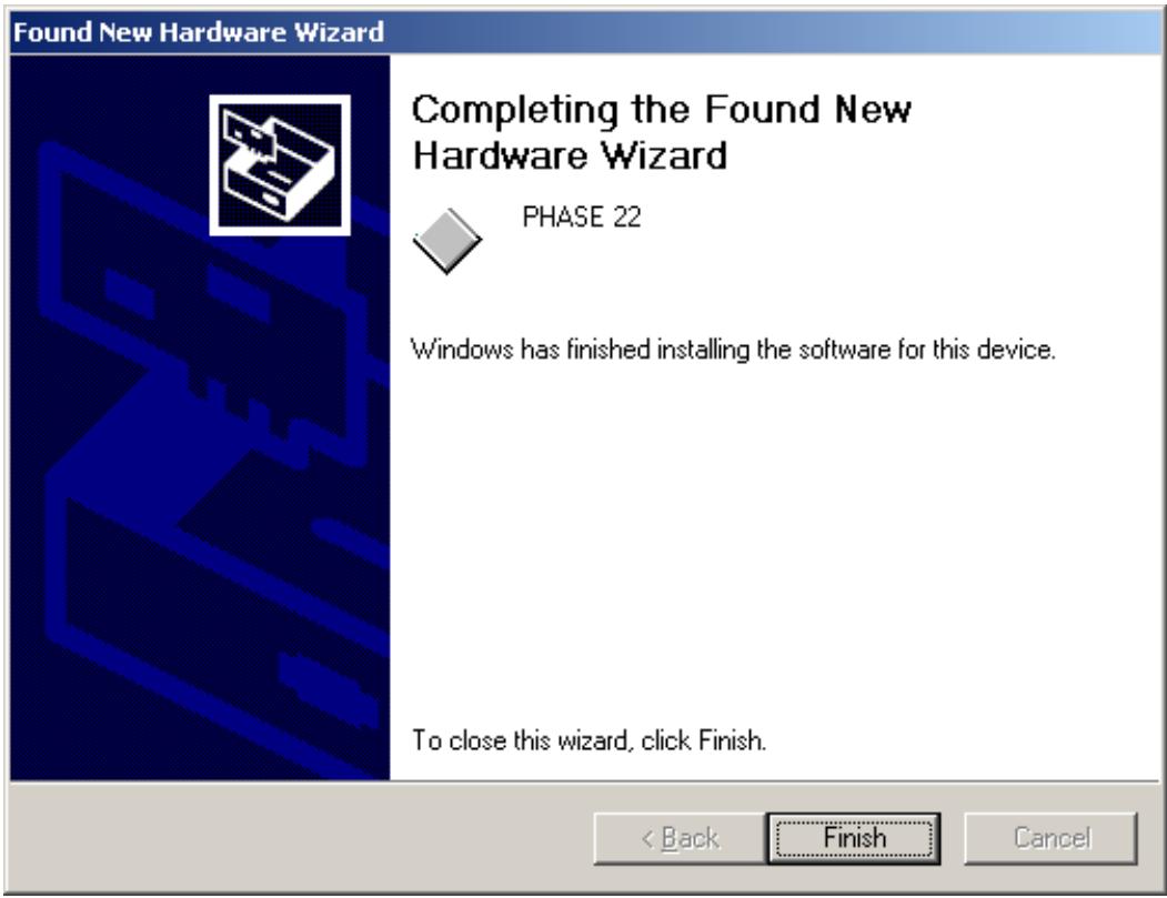
- In the final window, the hardware wizard will report that the driver software has been installed successfully. Close the wizard by clicking "Finish".
If Windows requests a second driver file, please refer to the aforementioned directory on the PHASE CD-ROM. It is also possible (e.g. if this is the first sound card installation in your system) that some additional Windows extensions have to be installed. Please have your Windows CD ready for this purpose.
If contrary to all expectations an additional request should appear for you to perform some action and you are not sure about it, then pressing the Enter key is generally a safe action.
After a successful driver installation, you should verify the correct condition of your Windows 2000 system. The Device Manager presents an overview of installed and recognized hardware components of your computer. The Device Manager can be found on the "Control Panel" under "System" > "Hardware". Then click the "Device Manager" button.
After successful driver installation, the PHASE 22 Control Panel can be installed easily using the autorun option (
Follow the instructions on the screen to install the various bundled software programs. The control panel application is also easy to remove from your system. To do so, open the "Add/Remove Programs" dialog from the Control Panel. Search for the program to be deleted, select it and click "Change/Remove".
Windows XP installation
- Boot your computer after installing the PHASE 22 PCI card.
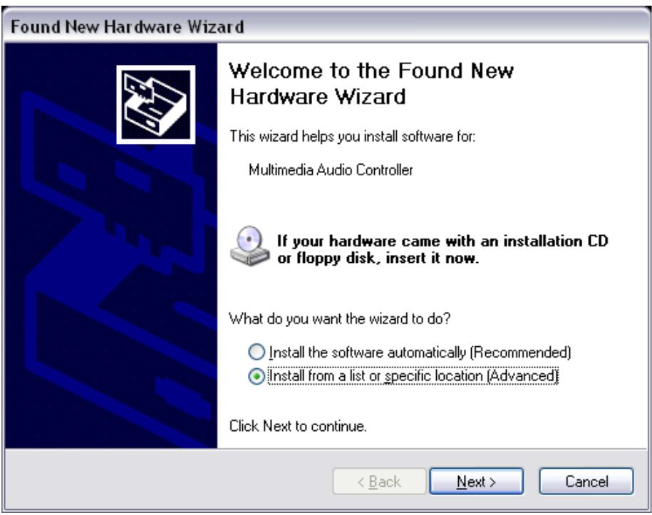
- During the boot, the Windows hardware wizard will identify the new hardware as a "Multimedia Audio Controller". If you have not done so already, insert the PHASE CD-ROM now. Finally enable the checkbox "Install software from a specific location [Advanced]" and confirm with "Next".
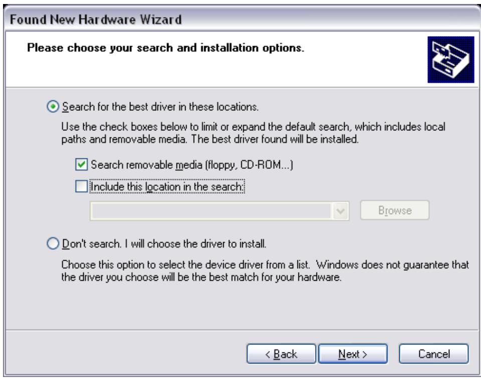
- In the next window enable the checkbox "Search removable media (floppy, CD-ROM, ...) and confirm with "Next".
- The following dialog box will now appear as the installation is continued:
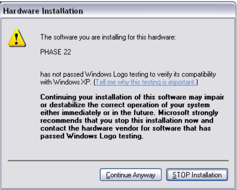
- This is no cause for alarm. Click "Continue Anyway" to continue. The installation will now be executed.
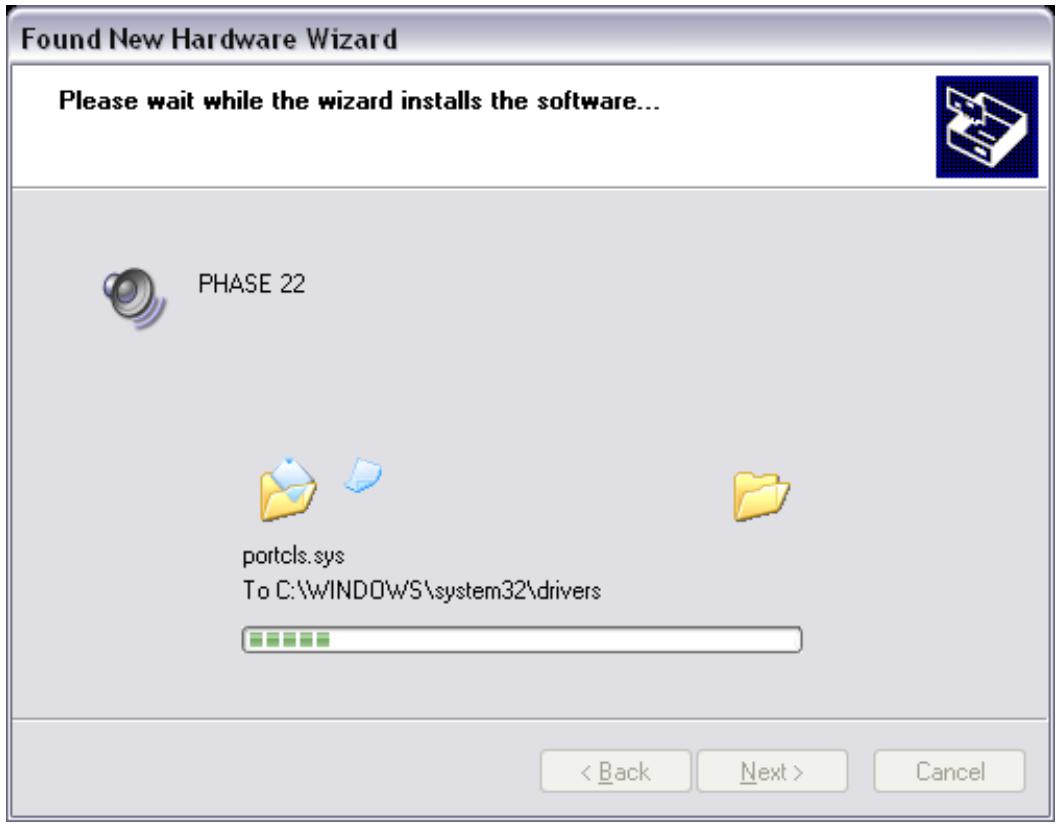
- In the final window, the hardware wizard will report that the driver software has been installed successfully. Close the wizard by clicking "Finish".
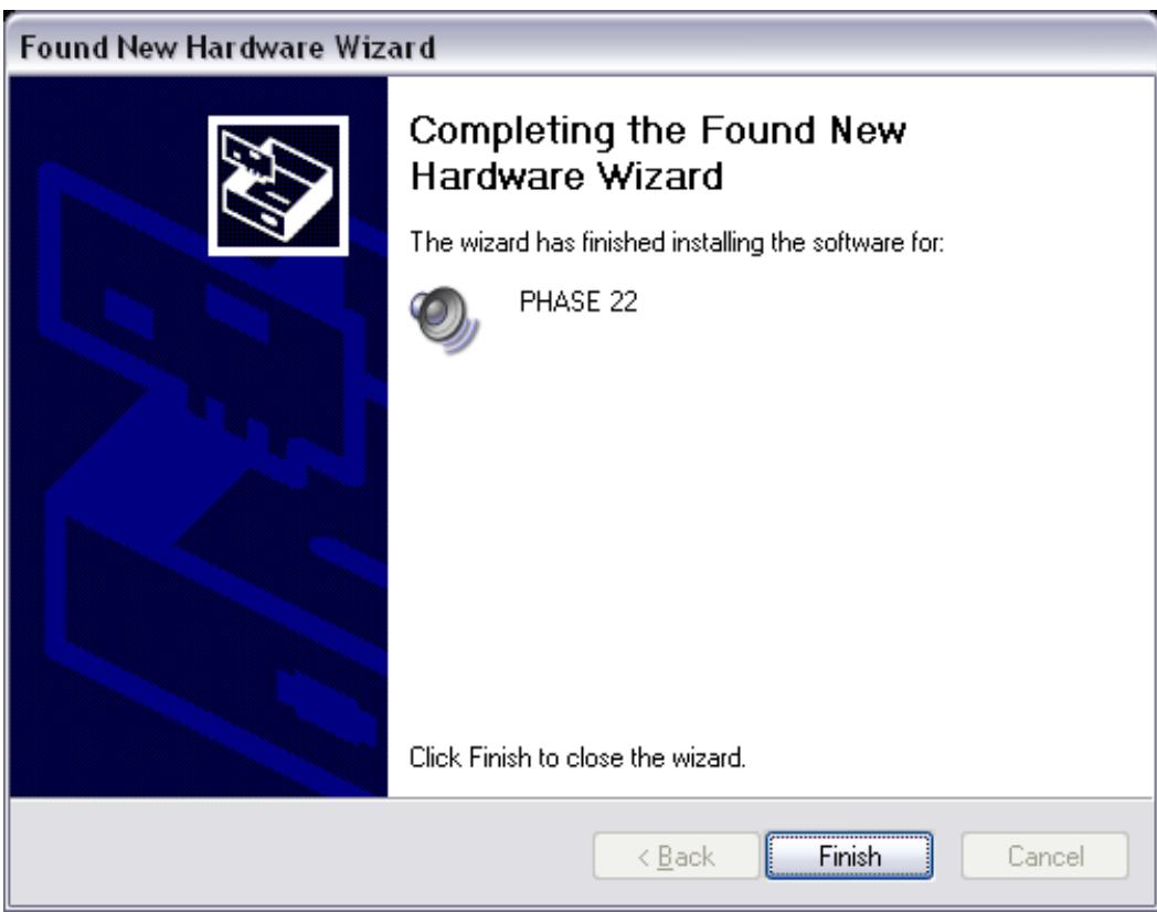
If Windows requests a second driver file, please refer to the aforementioned directory on the PHASE CD-ROM. It is also possible (e.g. if this is the first sound card installation in your system) that some additional Windows extensions have to be installed. Please have your Windows CD ready for this purpose.
If contrary to all expectations an additional request should appear for you to perform some action and you are not sure about it, then pressing the Enter key is generally a safe action.
After a successful driver installation, you should verify the correct condition of your Windows XP system. The Device Manager presents an overview of installed and recognized hardware components of your computer. The Device Manager can be found on the Control Panel under "System" > "Hardware". Then click the "Device Manager" button.
After successful driver installation, the PHASE 22 Control Panel can be installed easily using the autorun option (
Follow the instructions on the screen to install the various bundled software programs. The control panel application is also easy to remove from your system. To do so, open the "Add/Remove Programs" dialog from the Control Panel. Search for the program to be deleted, select it and click "Change/Remove".
Driver installation for Macintosh OS 10.x (OS X)
In the OS10 version, we recommend the Apple operating system update called "Jaguar" (current version 10.2.6). A version update, which can be obtained for an extra charge, contains some improvements specially geared towards audio applications. The system requirements are OS10.1 or higher. Furthermore, in order to install the drivers, you must have administrator rights on the system.
To install the PHASE 22 MAC OS X driver and Control Panel applications, select the program from the
After restarting the system, you can select the PHASE 22 Control Panel from the directory Macintosh HD -> Programs.
The connections of the PHASE 22 System
The PHASE 22 audio interface offers you all of the connections required for professional studio peripherals. Following is a detailed overview of its technical and electrical characteristics:
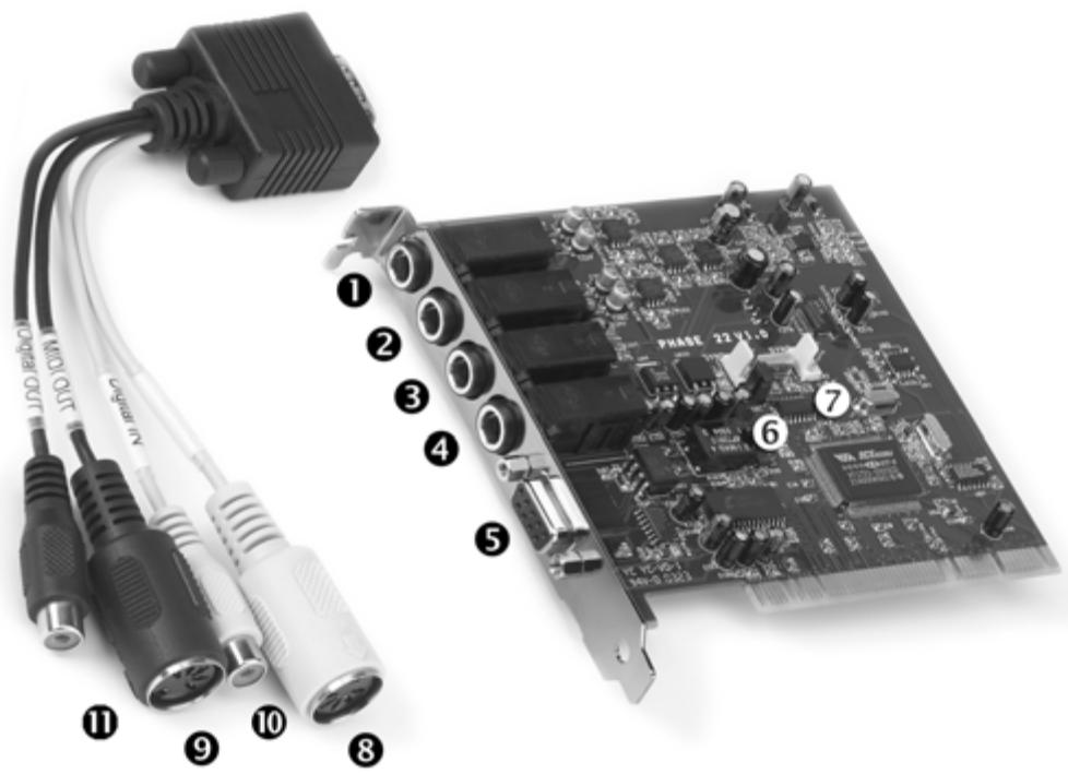
The PHASE 22 audio system
- Analog Line In 1, balanced 1/4" jack
- Analog Line In 2, balanced 1/4" jack
- Analog Line Out 1, balanced 1/4" jack
- Analog Line Out 2, balanced 1/4" jack
- Connection for the PHASE 22 breakout cable (Tighten the screws of the connector firmly to ensure that the cable is securely attached to the PCI system. The weight and stiffness of the cable may otherwise cause it to become detached.)
- EWS® Connect Sync IN connection for the internal synchronization of up to 4 PHASE PCI cards (5 pins, the jumper must remain in place on the master card). For more information, please also read “Cascading and internal synchronization” starting on page 36.
- EWS® Connect Sync OUT connection for the synchronization of up to 4 PHASE PCI systems (2 pins).
- MIDI In, 5 pin DIN connection
- MIDI Out, 5 pin DIN connection
- Digital In, coaxial, cinch connection
- Digital Out, coaxial, cinch connection
Analog outputs
The analog outputs of the PHASE 22 system operate with music-compatible line levels of +4 dBu (plus headroom, typically 2.2 V RMS). Here, you can connect a mixing card, active speakers, or amplifiers.

The PHASE 22 system has two high-quality analog outputs which can be independently addressed. The connections are in 1/4'' jack format and offer a balanced signal path to minimize interference. The outputs can be controlled as a pair using Stereo Link, or individually in mono, via the drivers or the PHASE Control Panel. However, you will usually control the volumes from within the audio software application you use.
The output level of all channels is fixed at around +4 dBu and offers enough headroom, should your production require it (including headroom, typically 2.2 V RMS).
Practical tip:Make full use of the 24-bit support of up-to-date software applications and connected digital peripherals - even if you are planning to "just" release your production on CD. The additional sound quality is audibly worthwhile, both in the sum of the signals and, above all, during digital postproduction.

Analog inputs
The analog inputs of the PHASE 22 System feature high-quality preamps with which you can manually control the converters. Here, you can connect the AUX or TAPE outputs of a mixing board, instruments with line level output, a tape recorder or similar peripheral gear.

The PHASE 22 system has two high-quality analog inputs, which can be independently addressed. The connections have been realized as 1/4 " jacks and offer a balanced signal path to minimize interference. Naturally, it is also possible to connect unbalanced mono jacks. The unused signal phase is automatically connected to the analog ground.
If the level of a connected device is too low, you can increase the signal by up to 18 dB in 0.5 dB steps with the controllers in the PHASE Control Panel. In the drivers as well as in the PHASE ControlPanel, the inputs are viewed as a stereo pair. As a rule, you can also combine the two channels for mono use in common audio editors.
Practical tip: While recording, try to achieve as high a recording level as possible to benefit best from the wide dynamic range of the 24-bit converter. As a rule of thumb for good recordings, always take the following into account: a clean "take" is much more valuable than the best plug-in for later sound correction.

Digital interface (S/PDIF, RAW, AC3)
Devices that can process the S/PDIF protocol or Dolby AC3/DTS signals can be connected to the coaxial digital interface (cinch plugs, RCA). This includes, for example, DAT recorders and many hi-fi components, or even other computers that you want to connect to the audio network (VST System Link).

Use the digital interface of your PHASE 22 system to transfer music digitally from your computer to other devices, or to record audio data with your computer. There are two separate coaxial jacks (RCA / jack) for recording and playback.
The cables for digital connections are always connected "crossover", meaning OUT to IN and vice-versa. Pulses are transmitted together with the audio data when the S/PDIF protocol is used. This is known as the sample rate. The interface of the PHASE 22 system can receive rates up to 96,000Hz and send rates up to 192,000Hz . You should keep this difference in mind if you plan to exchange digital data, for example using a ProTools system or a VST System Link. The correct driver for recording digital sources is called "PHASE 22 Digital".
You can find detailed information on the digital interface settings in the PHASE Control Panel beginning on page 30
Practical tip: If possible, use specially shielded RCA cables for transferring audio data, at least if it is important to have an absolutely clean, jitter-free signal path (for example, when mastering).

Advertisement ;-) TerraTec's Vice Versa is a compact S/PDIF converter, which allows audio devices to be connected with optical TOSLink connections to electrical cinch connections - and vice-versa. This clever switching technique allows you to select whether to use Vice Versa as a bi-directional converter or as a signal repeater. For more information, go to www.terratec.com.

MIDI interface
The MIDI interface of the PHASE 22 system allows you to connect the device with properly equipped peripherals such as MIDI keyboards, DAW controllers and countless other devices. The cables for MIDI connections are always connected "crosswise", meaning OUT to IN and vice-versa. MIDI sequencer software usually offers you to loop MIDI data through, using the Through function.
Practical tip: Even if your input keyboard (master keyboard) has a USB connection available, you should use the MIDI input (IN) of the PHASE 22 system whenever possible: the "direct connection" to the PCI data bus of the computer, and thus to the MIDI software, allows a substantially faster and more stable timing than most USB-MIDI interfaces. Of course, the same is true for the output when it is needed.

The drivers (Windows operating system).
The PHASE 22 audio interface features a range of drivers for a variety of applications. All drivers support all bit rates between 8 and 32-bit with all common sample rates between 8 and 96kHz , even 192kHz via the digital output. As a rule, the sample rates are not "interpolated". In other words, the system always automatically sets itself to the sample rate with which an application is recording or playing back. This prevents quality losses due to internal sample rate conversions. There are exceptions, however, which we will be covering below.
But now to the individual drivers.
The Wave driver
In most Windows programs, you will encounter drivers with the designation "PHASE 22 Wave" for recording and playback. The device structure corresponds to the format defined by Microsoft for WDM audio devices. If the PHASE 22 System is selected as the standard output device (e.g. Windows: Sounds and Multimedia Properties; MAC OS X: System Settings -> Sound) the audio output will be available on the two analog channels and in parallel at the digital output.
If you have cascaded multiple audio interfaces (see page 36) the operating system will number the individual driver names from 1 to 4.
Depending on the application, the driver names are displayed with supplements that refer to the audio architecture of the operating system: MME, WDM or DirectSound (see below for more information).
The ASIO driver
ASIO stands for "Audio Streaming Input Output" and refers to a 32-bit driver model developed by Steinberg. The advantage of the ASIO driver is its extremely low delay, also known as latency, during audio recording and playback. Values significantly lower than 10 ms can be achieved, ranging to less than 2 ms on fast and cleanly configured systems with sample rates above 88.2 kHz.
In addition, this format supports multi-I/O cards as well as direct monitoring. Programs that make use of Steinberg's ASIO interface indicate in the corresponding dialogs the ASIO drivers of the PHASE 22 System.
The ASIO driver is listed in compatible programs under "ASIO for PHASE 22". The inputs and outputs (usually "buses") available in the programs are called "PHASE (n) Out", where n is used to distinguish between multiple PHASE interfaces (1 to 4, see page 36). The output pair (1/2 and Digital Left/Right) is often only specified as the left channel, this refers to both channels, however.
The GSIF driver
The GSIF driver of the audio interfaces is also visible only in certain programs. The GigaStudio sampler application and other Tascam / Nemesys products can also access the hardware in a very fast and direct manner. The outputs available in each program are called here "PHASE 22 GSIF (n)" and lead directly to the outputs of the PHASE 22 audio system.
The MIDI driver
For the recording and playback of MIDI data via the MIDI IN and OUT jacks, a separate driver is available. The driver, which is designated as "PHASE 22 MIDI" in the system, can be selected in any situation in which its use is appropriate.
Practical tip: If MIDI files, which can be played back using Windows' media players, are also to be transferred to externally connected devices, open the "Sounds and Multimedia Properties" dialog window from the Windows Control Panel and set the "MIDI Music Playback" device to the driver mentioned above.

In detail - special properties of the drivers
The following contains in-depth information for those with the need to know. Less experienced users won't encounter any problems if they skip over this section.
32-bit data transfer
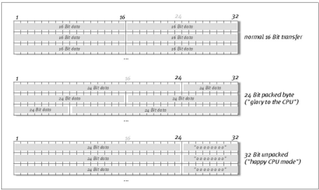
The drivers support a special data transfer format known as "32-bit unpacked". Audio data streams are transferred to the computer's main memory via the PCI bus. The PCI bus features 32 "lines" (32-bit). A PC generally takes care to ensure that its data lines are well-utilized. For this reason, 8-bit audio data is always sent on its way in groups of four packets (4 × 8 = 32) , and 16-bit data (2 × 16 = 32) in groups of two (diagram above).
The situation is a bit more complicated from the processing standpoint with 24-bit audio data: suddenly there's "only" 24 sweet-sounding bits available, i.e. 8 bits are "missing". The "24-bit packed" process solves this problem in the following manner: the computer CPU (your Pentium, for example) divides the 24-bit data into multiples of 32 (middle of diagram). That costs computing power and isn't really necessary.
The "32-bit unpacked" process fills the remaining bits with zeroes and the driver sends suitable 32-bit packets on their merry way. Most commonly-used applications currently support this process, which is particularly easy on the computer's resources (bottom of diagram).
DirectSound & WDM
It goes without saying that the drivers of the PHASE system also support Microsoft's DirectSound or DirectX3D interface. What's more, the software complies strictly with Microsoft's WDM specification. WDM (Windows Driver Model) is a recent driver concept from that popular Redmond-based software manufacturer which also involves a number of innovations in the audio sector. For example, the drivers are able to play back audio data streams from multiple applications in parallel (multi-client, a "luxury" that faithful TerraTec customers have enjoyed since 1997).
WDM sample rate (SR) interpolation
The multi-client capability of the WDM architecture also permits the simultaneous playback of multiple audio data streams with differing sample rates. The sampler frequency used for all streams is based on the file with the highest sample rate. All further data streams are interpolated as required and their pitch is not affected.
SR conversion and interpolation always involves a certain loss of quality, so if you are using applications where the highest possible audio quality is important, make sure that multiple programs are not using different sampling rates simultaneously. For example, it's best to only have the playback software running when transferring a piece of music at 44.1 kHz to a DAT recorder.
WDM kernel streaming
WDM kernel streaming also represents a new technology for Microsoft. Like already established models such as Steinberg's ASIO interface, kernel streaming permits extremely fast access to the audio hardware. The deployed software (such as audio/MIDI sequencers or software synthesizers) must support the WDM function directly, however. One of these programs, for example, is the "Sonar" recording software produced by the Cakewalk company.
The MAC OS X drivers
The driver version available for the current, first shipment is based completely on the MAC OS X CoreAudio or CoreMDI concept. With the help of the CoreAudio support, the PHASE 22 system can be used with extremely low latencies within an Audio/MIDI sequencer (e.g. Emagic Logic or Cubase SX). A special ASIO driver is not mandatory. As soon as the software products announced by the Steinberg company allow direct ASIO connection to the hardware, the development of corresponding PHASE 22 PCI card support is planned.
Under System Settings -> Sound, the PHASE 22 system can be set up as the default audio system in OS X.
The Control Panel
The PHASE Control Panel is - beside the drivers - by far the most important piece of software in the package. Here, depending on the requirements of each situation, you can have total control of the audio interface, reduce volumes (take this literally!), control the two input preamplifiers, as well as load and save settings.
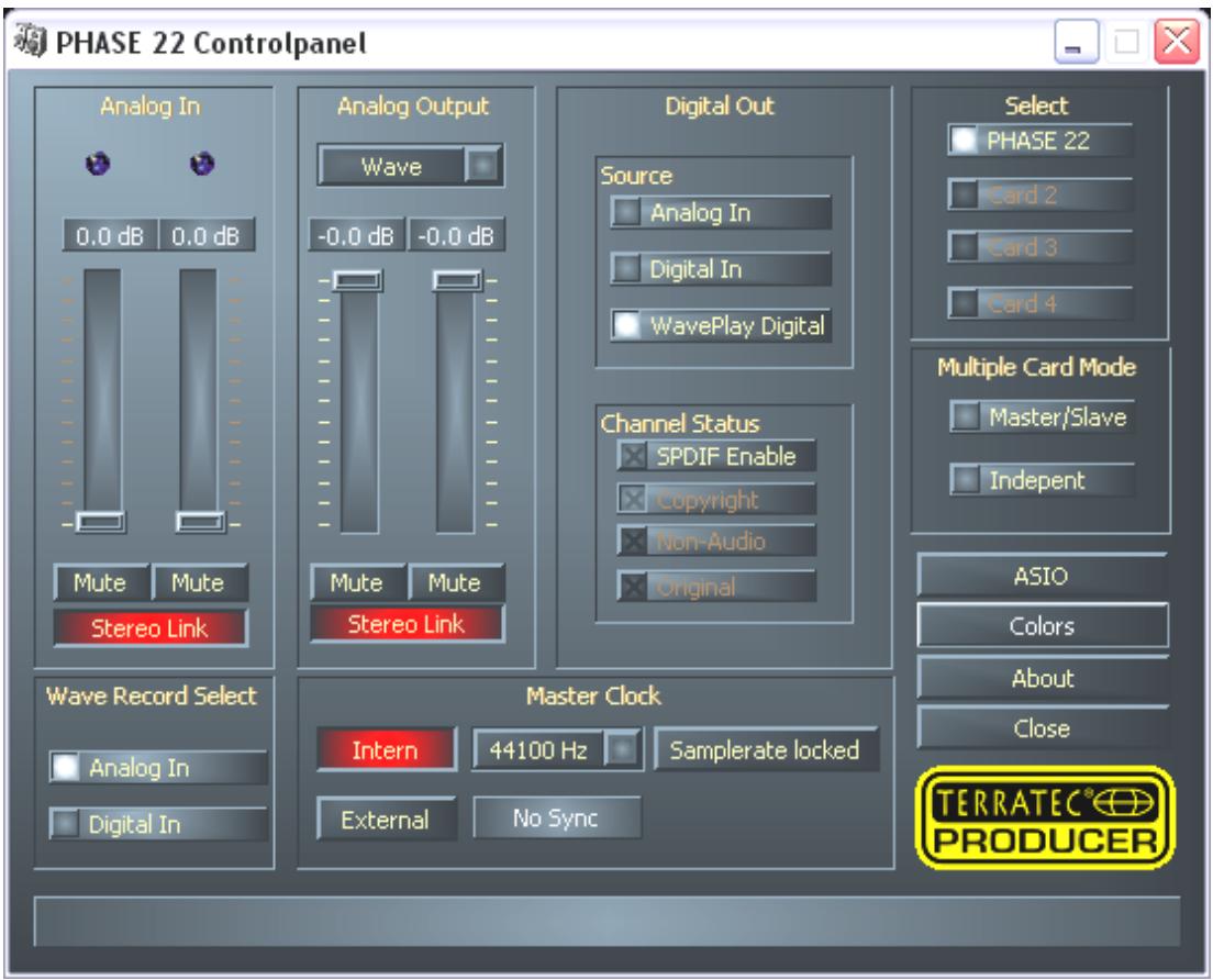
The Control Panel under Windows
The Control Panel under MAC OS X
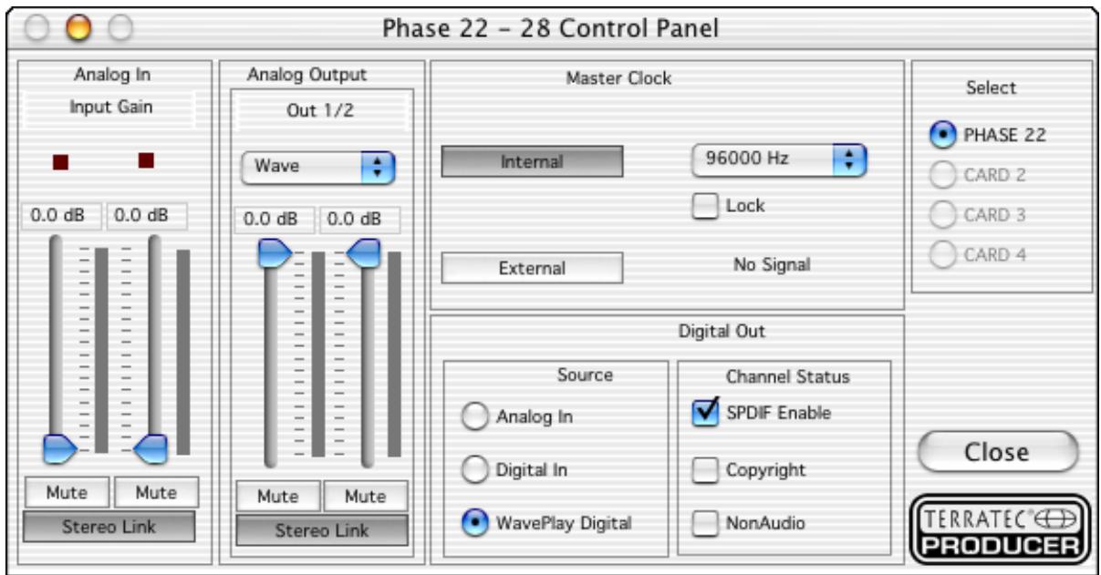
How does the Control Panel work?
The Phase Control Panel and the routing (signal flow within the card) is very easy to understand. You still want to know what it is all about? Very well: the following are the individual function blocks, from left to right:
Analog In
The Analog In section of the PHASE Control Panel controls the levels of the analog inputs. If the input level of a connected device is too low, you can increase it here by up to 18 dB in 0.5 dB steps. A VU meter is available for visually monitoring the levels, and the two LEDs warn of excessive levels and (impending) distortion. A yellow light signals the -1 dB threshold, red indicates a signal in excess of 0 dB resulting in audible distortion.
Wave Record Select
Here, you can select whether to record a signal by analog or digital input. The signal can be recorded via the "PHASE 22 WAVE" driver by the application you choose.
When recording from digital sources, you should pay attention that the sampling rate is synchronized correctly (see Master Clock below).
Note: Applications based on the PHASE 22's ASIO driver (Windows) or CoreAudio (MAC OS X), have simultaneous access to the analog and digital inputs.
Analog output
The Analog Output section of the PHASE Control Panel controls the output levels of the analog outputs addressed by the output (WAVE) drivers. The dropdown menu lets you monitor the digital or analog input instead of the WAVE device.
In addition, you can lock the two faders in relation to one another with the "Stereo Link" button. The "Mute" buttons can be used to mute the individual channels.
Practical tip: If you are working with common audio/MIDI sequencers, you should also use the this software for volume control. The advantage is that the settings are usually saved together with your project (song, arrangement etc.), and do not need to be loaded first from the PHASE Control Panel.

Master Clock
Here we're dealing with the sample rate used by the PHASE 22 audio interface. This is a very important point, as the system can be clocked by an external signal (External, e.g. from a DAT recorder) or it can set a sampler rate itself and provide this signal to other devices.
You can choose from all commonly used sampler rates from 32 to 192kHz - the actual bit rate is not important at this point. In the case of external synchronization (i.e. via a signal applied to the digital interfaces or the internal connection to cascade multiple cards), the external sampler rate will be displayed. If no signal is available or the connection has been interrupted, the message "No Sync" will be returned.
The "Samplerate locked" switch also allows you to set the sampling frequency to a specified value (or when using external synchronization, the externally preset value). Doing so ensures that only this sample rate will be accepted by the PHASE 22 system. However, remember that in "non-ASIO" mode, the operating system's own sampling rate converter (SRC) may convert automatically to the required values. Example: The PHASE 22 PCI card is set to 44.1kHz and Windows Media Player, or I-Tunes on MAC OS X systems, is playing a 48-kHz file. In this case, the signal is down-sampled to 44.1kHz , and every form of SRC leads to a certain degree of quality loss.
Practical tip: The audio controller of the PCI card does not feature a sample rate converter. This module - which is common on consumer sound cards - normally lets you play back signals with a variety of sampler rates by "interpolating", as needed, the sample rates in real time to a specific frequency. This process is now controlled by the operating system. Therefore, make sure when outputting your production (if not earlier) that the sampling rate of your project matches the audio interface's sampling rate.

DIGITAL OUT
As in the drop-down menu of the Analog Out area, here you can select one of three signals for digital output: the analog input, its digital counterpart, or the WAVE output (in other words: your audio application).
Channel Status
Here, you can define whether a signal you send via the digital interface conforms to the S/PDIF protocol and should contain certain copy-protection information. It is possible to add copy-protection information (original) to your recording when transferring it to another device. This can be useful when recording a composition to DAT or a MiniDisk as a demo to prevent (digital) copies from being made.
S/PDIF Enable defines the outgoing signals as S/PDIF data stream. This is the most commonly available transfer protocol and is "understood" by most professional and consumer devices.
Copyright adds a (S/PDIF) copy-protection ID to the signal or filters it out when deactivating copy protection. This function sets the so-called "copy protection bit" which ensures that no digital copies can be made of the signal. Please note that this "protection process", like other similar processes, only provides extremely marginal protection of your work.
NonAudio adds information to the data stream that defines it as "anything, but not only audio" so that it can be reproduced in RAW format (e.g. for AC-3 / DVD Audio, see below).
- Original activates the so-called "generation bit", permitting exactly one digital copy to be made. Disabling this function sets the bit to 0 - you can then copy to your heart's content.
ASIO (Windows)
Programs that support Steinberg's ASIO feature dialogs containing special settings for these drivers. The properties of the PHASE hardware can be set up in the ASIO Control-Panel.
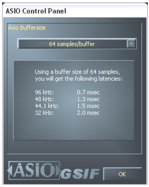
The ASIO buffer size (Windows)
has a direct effect on the latency ("speed") of the ASIO driver; if the value is too low it may impair the overall performance of your system, however. On fast systems (1 GHz or higher), you should be able to set values of less than 512 samples/buffer (this corresponds to a latency of less than 5 ms at 96 kHz) without problems.
"Without problems" means that you will not detect any dropouts during audio recording or playback. If such dropouts occur, increase the number of buffers. The "conversion" into time values is displayed just below the menu.
Card(s) used for ASIO - cascaded PHASE systems only
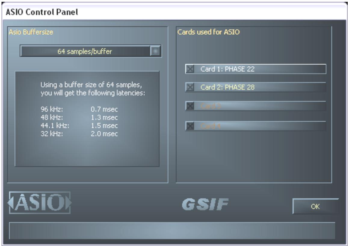
Select the cards here that are to be combined into "one card" in an ASIO combination. The highlighted cards then appear in the application as one (1) ASIO device with the corresponding number of inputs and outputs. Cards that are not included in the ASIO combination can be used separately with the GSIF driver.
Colors
Here you can configure perhaps the most vital system settings within the PHASE ControlPanel. No matter where you look, our days are filled with color. After all, life is beautiful, and there's nothing like pink buttons and delicate green reflections to breathe life and good cheer into your boring Windows desktop. Have fun...! ;-)
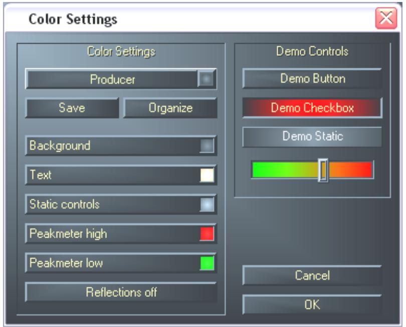
But seriously, folks - this section contains a number of truly useful settings that not only beautify your PHASE ControlPanel, but which improve the overview of its display:
A click on the Background, Text, Static Controls and Peakmeter buttons opens the Windows dialog to change the colors.
The "Reflections off" option disables the attractive reflections of the elements. This can be helpful for slower systems.
Test the settings made above in the right-hand part of the window and save them when you're satisfied.
Once saved, you can find your personal color settings in the dropdown menu, which already contains a number of examples. The "Windows System" color set uses only colors that display correctly at an 8-bit color depth.
Other tips for operation:
You can change the names displayed in the Analog Out area add clarity to your overview. Simply double-click on Out 1/2 and enter a new name (for example, the name of a connected device).
Hover over one of the colorful VU meters briefly with the mouse cursor and the current peak signal level will be displayed.
The VU displays can be disabled with a right-click to conserve system resources.
A mute switch silences the relevant signal completely, whereas it can still be heard faintly when the fader has been pulled all the way down.
The stereo link function (enabled by default) permits the left and right signals to be adjusted simultaneously.
Cascading and internal synchronization
The PHASE 22 System can be used with up to 3 further PHASE 22 or 28 audio systems in the same computer and even operated as a closed system. You can therefore conveniently increase the number of input and output channels which can also access directly from most Windows/MAC applications. A fully loaded system containing four PHASE 22 models thus features a total of 8 inputs and outputs - and all of that with virtually the same low latency! You can also integrate the PHASE 28 System in your setup to expand the number of analog outputs.
For no-error operation, the PCI cards must be connected to each other using a special cable (included with each card) or the WordClock module, which is available separately.
The internal connection (recommended).
There are two short pin sets next to each other on the PCI card: Sync In (5-pin) and Sync Out (3-pin). These are necessary to ensure that multiple cards in one system can function properly. As soon as you install another card in the system, these must be connected to each other. Additionally, the "MasterClock" must be configured later in the PHASE ControlPanel.
Sync-In/Sync-Out
If you only have one card in the system, just leave everything the way it is: on the Sync IN there is a jumper on the black pins 1-2, which sets the card as a master. Sync Out remains empty.
When connecting additional cards, connect the 3-pin end of the included EWS connect cable with the Sync Out on the master card. Connect the other 5-pin end to the Sync In of the other card. Please keep the remaining jumper on the second card.
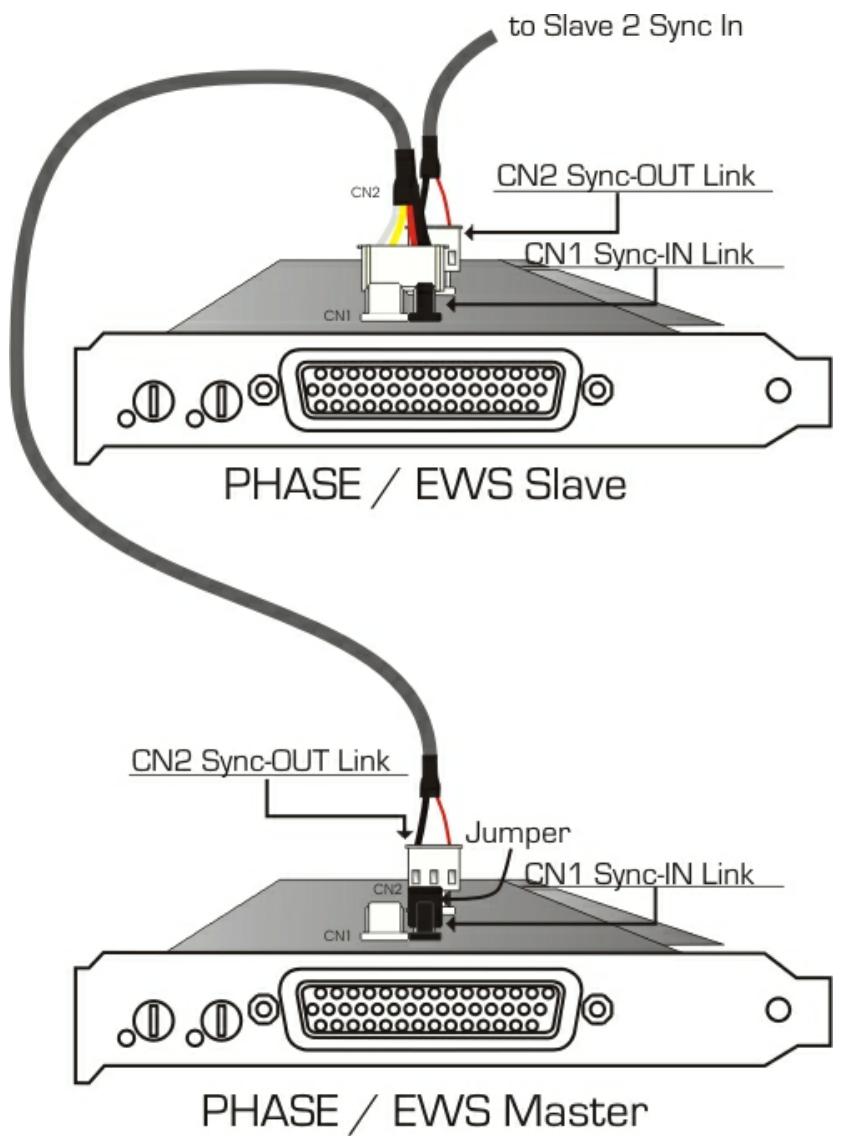
Still more cards? No problem: Simply attach another cable from the Sync-Out of the second card to the Sync-In of the third. And, last but not least, a cable from the Sync-Out of the third, to the Sync-In of the fourth (and last) PCI card.
The PHASE Control Panel
The PHASE ControlPanel will now automatically configure the MasterClock settings, since the cards are now digitally synchronized. The clock of the first (master) card is now set to "Internal". All additional cards (you can select the models on the right-hand side of the ControlPanel with "Select Card#") are now set to external synchronization.
All interfaces will now run using the sampler frequency set on the master. If you would like to also use an external clock for the first card (using a DAT recorder, for example), set its master clock to "External" as well. The sync information are transmitted accordingly.
Tips, tricks & things worth knowing
Dolby AC3 and DTS
*The digital interfaces of the PHASE 22 system can also be used independently of the S/PDIF standard (see also page 37 Digital-Out at "NonAudio"). Various manufacturers of software DVD players support playback of DVD studio material over the PHASE series of TerraTec Producer. Signals in Dolby AC3 or DTS format can therefore also be transferred using the digital interfaces.
Always with the beat - digital synchronization
When recording with the digital interface, make sure that the sampling frequency (rate) of the card matches that of the device from which you are recording. To ensure correct synchronization of the devices, you must switch the MasterClock to "External" in the PHASE Control Panel (see also page 36).
If you forget this step, audible errors such as dropouts and clicks may occur during recording - and already when monitoring the signal. And also in the reverse situation (an external device should run at the same rate at the audio system), make sure that settings of your additional peripherals match. The PHASE Control Panel must be set to "Internal" in this case (such as during operation without externally connected digital devices). If the devices are to be permanently connected to one another in both directions, you must decide which device will provide the clock signal.
The digital interface of the PHASE 22 audio system transfers all bit resolutions between 8 and 24 bits and all sampling rates between 8 and 96kHz (Digital Out at up to 192kHz ). Please note that not all devices can process sample rates higher than 48kHz . To transfer a signal recorded at 96kHz to a DAT recorder, it's necessary to use suitable software to convert the file(s) to 44.1kHz or 48kHz first.
About IRQs and other interrupts
Basics:
IRQ stands for "Interrupt Request". An IRQ is used to inform the processor that a device wants to perform a specific action. This is done over what are known as interrupt lines, which can stop the processor and demand it perform a calculation.
Since the introduction of the PIC (Programmable Interrupt Controller) a PC has 16 interrupt lines, most of which are already in use, as you can see below. More modern motherboards generally use an APIC (Advanced Programmable Interrupt Controller), which can manage more than 32 IRQs.
| IRQ | Device |
| 0 | System timer |
| 1 | Keyboard |
| 2 | Cascaded for IRQ 8 to 15; from AT replaced by IRQ 9 |
| 3 | Serial port (COM2) |
| 4 | Serial port (COM1) |
| 5 | Free |
| 6 | Disk drive controller |
| 7 | Parallel port (LPT1) |
| 8 | Real-time clock |
| 9 | Free |
| 10 | Free |
| 11 | Free |
| 12 | PS/2 Mouse |
| 13 | Mathematical coprocessor |
| 14 | Primary IDE controller |
| 15 | Secondary IDE controller |
Unfortunately the computer does not run like that, because at that time a graphics card was not considered. In addition, most modern PCs have at least one USB controller, often a network, possibly a Raid controller and even onboard sound. As you can see, there is a shortage of IRQs, particularly if another card is installed in a PCI slot.
Please disable all devices that are not required (e.g. the COM ports are only rarely used) in the computer BIOS. See the documentation for your motherboard to do this. The "free" IRQs can now be used in the PCI bus.
PCI Bus:
There are generally only four "real" interrupt inputs available for the PCI bus, eight with modern motherboards with APIC. This means that even if you have six PCI slots on your motherboard, they have to make do with four or eight IRQs. The AGP port, USB and possibly the Raid controller also use these IRQs and with newer cards there is also onboard LAN, 1394 (FireWire) and SATA (serial ATA - new transfer standard for hard disks). It is impossible to avoid sharing an interrupt between multiple PCI slots. Unfortunately, there are no rules covering this and the motherboard documentation is the only refuge. Every motherboard has an IRQ table for the PCI bus; we will explain this assignment in more detail with the example of the "ABIT KT7A-Raid" and the "ASUS A7V8X":
ABIT KT7A-Raid
| Device | A | B | C | D |
| PCI Slot 1 | shared | - | - | - |
| PCI Slot 2 | - | shared | - | - |
| PCI Slot 3 | - | shared | - | - |
| PCI Slot 4 | - | - | - | shared |
| PCI Slot 5 | - | - | shared | |
| PCI Slot 6 | shared | |||
| AGP Slot | shared | - | - | - |
| USB Controller | - | - | - | shared |
| Raid Controller | shared |
A to D stands for the four available IRQs on the PCI bus.
- A is available for PCI slot 1 and AGP slot.
- B is available for PCI slot 2 and 3.
- C is available for PCI slot 5 and the Raid controller.
- D is available for PCI slot 4, 6 and the USB controller.
The result is that:
PCI slot 1 and AGP slot share an IRQ
PCI slot 2 and 3 share an IRQ
PCI slot 4, 6 and USB controller share an IRQ
PCI slot 5 and Raid controller share an IRQ
ASUS A7V8X
| Device | A | B | C | D | E | F | G | H |
| PCI Slot 1 | - | - | - | shared | - | - | - | - |
| PCI Slot 2 | shared | - | - | - | - | - | - | - |
| PCI Slot 3 | - | shared | - | - | - | - | - | - |
| PCI Slot 4 | - | - | shared | - | - | - | - | - |
| PCI Slot 5 | - | - | - | shared | - | - | - | - |
| PCI Slot 6 | shared | - | - | - | - | - | - | - |
| AGP Slot | shared | - | - | - | - | - | - | - |
| USB 1.1 UHCI 1 | - | - | - | - | - | shared | - | - |
| USB 1.1 UHCI 2 | - | - | - | - | - | shared | - | - |
| USB 1.1 UHCI 3 | - | - | - | - | - | shared | - | - |
| USB 2.0 EHCI | - | - | - | - | - | shared | - | - |
| AC 97 Codec | - | - | - | - | - | - | used | - |
| Onboard LAN | - | - | shared | - | - | - | - | - |
| Onboard 1394 | - | shared | - | - | - | - | - | - |
| Onboard SATA | - | shared | - | - | - | - | - | - |
| Onboard IDE | - | - | - | - | used | - | - | - |
A to H stands for the eight available IRQs on the PCI bus.
A is available for PCI slot 2, 6 and the AGP slot.
- B is available for PCI slot 3, onboard 1394 (FireWire) and SATA.
C is available for PCI slot 4 and onboard LAN.
- D is available for PCI slot 1 and 5.
E is available for the IDE controller.
- F is available for the USB controllers.
G is available for AC 97 sound chip.
- H is not used.
The result is that:
PCI slot 2, 6 and AGP port share an IRQ.
PCI slot 3, onboard 1394 (FireWire) and SATA share an IRQ.
PCI slot 4 and onboard LAN share an IRQ.
PCI slot 1 and 5 share an IRQ.
the IDE controller has its own IRQ.
- the USB controllers have their own IRQ.
- the AC97 sound chip has its own IRQ.
As you can see the installation position has a great influence on the IRQ assignment in the system, and to assign an IRQ to a device you can, for example, use the second PCI slot on the ABIT board but then you must leave the third free. For example, on the ASUS board that would be slots 1 and 5.
To check the IRQ assignments in your system, open the Device Manager in Windows 98 and ME, double-click System, and you will find the IRQ list there. In Windows 2000 and XP the Control Panel does not usually show the IRQ assignments correctly because of virtual CPI IRQ assignments. In these operating systems you must view the PCI Device List, which appears briefly during the boot process. The "actual" IRQ assignments are shown there, but with modern PCs there is usually no time to look at the list during startup, because it appears and disappears much too quickly. Tip: select the floppy disk drive as the first boot device and insert an empty diskette. When the error message warning of a missing operating system appears, you will also be able to see the PCI Device List - .
Exclusive or shared IRQ?
Basically, all modern PCI cards with WDM drivers support IRQ sharing, but under some circumstances this can cause problems. For example, if the sound card requests an interrupt request during playback or recording of an audio file but the request cannot be carried out immediately, perhaps because the ISDN card is also using this IRQ and the IRQ controller must first query which device is actually requesting the IRQ, this can cause interference like static and crackling as a result of missing samples.
Our hearing is (fortunately) one of our most sensitive organs and therefore every sample that is missed during playback is immediately obvious. Your eyes would not even notice a brief delay during web surfing caused by the ISDN card not reacting immediately, but your ears are less forgiving. So this apples for sound cards: give it its own IRQ to keep your ears happy!
Technical data
PCI audio interface
2 analog input channels, 1/4" jack, balanced
2 analog output channels, 1/4" jack, balanced
Coaxial digital input, cinch
Coaxial digital output, cinch
■ MIDI interface with 5 pin DIN connection
- Analog playback with up to 24 bit/96 kHz resolution
- Analog recording with up to 24 bit/96 kHz resolution
Digital playback with up to 24 bit/192 kHz resolution
Digital recording with up to 24 bit/96 kHz resolution
Digital interface for S/PDIF, AC3 and DTS formats
24 bit/96 kHz A/D converter with 100 dB (A) SNR^ , typically 102 dB (A)
24 bit/96 kHz D/A converter with 110 dB (A) SNR^ , typically 110 dB (A)
2.2 V RMS output level
EWS Connect connection for synchronized cascading of additional PCI systems**
*) This information depends on the technical data of the converter used
**) You can cascade and synchronize PHASE 22 and PHASE 28 audio systems with an EWS Connect connection. You can control up to four systems in one PC with only one driver and one ControlPanel.
Software
WDM drivers for Windows 98SE/ME/2000 and XP
Core Audio and Core MIDI support for Mac OS X
Support for ASIO 2.0 - Windows only
Support for GigaStudio (GSIF) - Windows only
WDM Kernel Streaming (e.g. Sonar) - Windows only
Support for MME and DirectX - Windows only
ControlPanel for Windows 98SE/ME/2000/XP and MAC OS X
System requirements/recommendation
System requirements PC:
- Pentium II 450 MHz
- 128 MB RAM
- VGA video card, 800x600 / 256 colors
- Windows 98SE/ME/2000 or XP
System recommendations PC:
- Pentium III 1 GHz
- 256 MB RAM
- VGA video card, 1024x768 / HiColor
System requirements MAC:
-G4800MHz
- 256 MB RAM
- VGA video card, 800x600 / 256 colors
-OSX
System recommendations (MAC):
-G41GHz
- 512 MB RAM
- VGA video card, 1024x768 / HiColor
-OSX