
CD-S5 - CD Player VINCENT - Free user manual and instructions
Find the device manual for free CD-S5 VINCENT in PDF.
| Product type | CD audio player |
| Brand | VINCENT |
| Model | CD-S5 |
| Dimensions (W x H x D) | 430 x 135 x 330 mm |
| Weight | 10 kg |
| Power supply | 220–240 V / 50 Hz, max. power consumption 25 W |
| D/A converter | 24-bit / 192 kHz |
| Frequency response | 10 Hz – 20 kHz (±0.5 dB) |
| Distortion factor | < 0.003% |
| Signal-to-noise ratio | 95 dB |
| Dynamic range | 100 dB |
| Output impedance | 600 Ω |
| Audio output voltage | 2.5 V |
| Crosstalk | 90 dB |
| Analog outputs | 1 pair RCA (unbalanced), 1 pair XLR (balanced) |
| Digital outputs | 1 coaxial RCA, 1 optical Toslink |
| Power control | Trigger input and output 3.5 mm (Power Control) |
| Remote control | Infrared, max. range 7 m, AAA batteries (LR3) |
| Playback functions | Play/Pause, Stop, Next/Previous track, Fast forward/rewind, Programming (PGM), Repeat (1/ALL), Random (RANDOM), Intro (10 s), A-B loop, Remaining time display (REMAIN), Brightness adjustment (DIMMER), Analog output volume adjustment (VOL+/–) |
| Maintenance and cleaning | Disconnect before cleaning; use a soft, lint-free, damp cloth; avoid abrasive products, solvents, thinners |
| Safety | Do not open the device; no user serviceable parts; disconnect mains before handling; protect from moisture, heat, vibrations; keep 5 cm clearance around for ventilation |
| Spare parts / Repairability | Mains fuse (under fuse holder); Vincent cables recommended; repairs by qualified personnel only |
| Available colors | Black, Silver |
| Included accessories | 1 power cable, 2 RCA audio cables, 1 remote control, 2 AAA batteries, 1 manual, 1 Power Control cable |
Frequently Asked Questions - CD-S5 VINCENT
User questions about CD-S5 VINCENT
0 question about this device. Answer the ones you know or ask your own.
Ask a new question about this device
Download the instructions for your CD Player in PDF format for free! Find your manual CD-S5 - VINCENT and take your electronic device back in hand. On this page are published all the documents necessary for the use of your device. CD-S5 by VINCENT.
USER MANUAL CD-S5 VINCENT
Instructions for use
english

we thank you for the confidence you prove in purchasing our product. It will match your high demands towards sound and manufacturing quality.
Though it is understandable that you want to plug and play this product instantaneously, we encourage you to read this manual carefully before installation. It will help you in handling and operating this machine in your system and obtaining the best possible performance, even if it was installed by your dealer.
Please follow the security precautions, though some instructions may seem obvious.
In the appendix to this manual you will find a glossary explaining some established technical terms. If there are open questions your audio specialist dealer will help you. He also represents your contact person in case of needed warranty service or repairs after the warranty period and is interested to hear from your experiences with Vincent products.
We wish you plenty of joy with your / our product,
your Vincent-Team
Cher client,
Safety guidelines 24
Other instructions 25
Included in delivery 26
Description of the appliance 26
Remote control 29
Installation 32
Operating the appliance 36
Tips 40
Search for errors 41
Technical specifications 42
Glossary 43
english
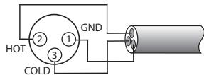
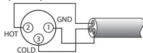
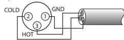
- USA System (Pin 2 = COLD, Pin 3 = HOT)
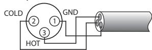
- Europäisches System (Pin 2 = HOT, Pin 3 = COLD)
Optischer Anschluss
This appliance was produced under strict quality controls. It complies with all established international safety standards. Nonetheless, the following instructions should be fully read and observed in order to prevent any hazard:

Do not open the appliance! Risk of electric shock! There are no parts in the appliance that require maintenance by the user.

Maintenance/Alterations

All equipment that is connected to the domestic mains voltage can be dangerous to the user if not handled properly. Leave maintenance work to qualified professionals. The product is only permitted for connection to AC 230Volt/50Hz, for earthed sockets and use in enclosed areas. Altering the product or manipulating its serial number voids the warranty. After a fault, leave the appliance's fuse to be replaced only by a professional with one of the same kind.
Power Cable Connection
Always pull the plug and never the power cable if you want to disconnect the appliance from the mains power. Make sure when setting up the appliance that the power cable is not squashed, severely bent or damaged by sharp edges. Do not touch the power lead with wet or damp hands. Use the power cable supplied or another one from Vincent.

Switching Off
Switch the appliance off every time before you connect or remove other components or loudspeakers, disconnect or connect it to the mains power, leave it unused for a longer period or want to clean its outside. On all amplifiers and receivers, wait approx. 1 minute after this before disconnecting or reconnecting the cable.
Moisture/Heat/Vibration
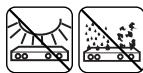
Contact of electrically operated equipment with liquids, moisture, rain or water vapour is dangerous for such equipment and the user and must be avoi
ded without fail. Take care that no liquids or objects get inside the appliance (ventilation slots etc.). It must be disconnected from the mains power immediately and examined by a professional if this happens. Never expose the appliance to high temperatures (direct sunshine) or strong vibration.

Heat Build-up
Make sure that a gap of 5cm remains around the appliance and that the surrounding air can circulate (do not install in enclosed cupboards). Vents must not be covered up.

Volume
The maximum tolerable volume is always reached well below the maximum possible setting on the amplifier. Be careful with the volume setting, therefore, in order to prevent damage to hearing. So that you do not expose yourself to high volumes unintentionally, always set to a low level before changing the input channel.

Cleaning
Pull out the power plug before cleaning the outside of the product. Whenever possible, use a soft, lint-free cloth that has been dampened. Do not use abrasives, solvents, thinners, flammable chemicals, polishes and other cleaning products that leave marks.

Batteries
Take note of the instructions for using batteries in the chapter "Remote Control".
OTHER INSTRUCTIONS
Setting up the appliance

How the system is set up has an effect on the sound quality. Therefore only place it on a suitable, stable surface. To make the most of your system's sound quality, we recommend placing the equipment on Vincent racks and not putting them on top of each other.
Old electronic equipment

This appliance is subject to the conditions set out in the European Directive 2002/96/EC. This is identified by the symbol of a crossed out waste bin on the appliance.
What this means for you as a consumer:
All old electrical and electronic equipment that is no longer used must be disposed of separately from domestic waste using places provided by the authorities. By doing so you can prevent damage to the environment and help to encourage manufacturers to produce more durable or reusable products. For further information about disposing your old appliance, please consult your local authority, waste disposal agency or the shop where you bought the product.
CE sign

This appliance complies with the current EU directives about attaining the CE mark and thus meets the requirements for electrical and electronic equipment (EMC regulations, regulations and regulations for low voltage equipment).

Declarations
This document was written by Andreas Böer. It is a product of Sintron Vertriebs GmbH, 76473 Iffezheim and may not be copied or distributed partly or in full without express, written consent.
Vincent is a registered trademark of Sintron Vertriebs GmbH, 76473 Iffezheim.
Vincent works continually to improve and develop its products. Therefore, the appearance and technical design of the appliance are subject to changes, as long as they are in the interest of progress.
The content of these instructions is for information purposes only. It can be changed at any time without prior notice and does not constitute any obligation on the part of the trademark's owner. The latter assumes no responsibility or liability for errors or inaccuracies, which may be included in these operating instructions.
Storage of the packaging
We strongly recommend that you keep the original packaging in case you need to transport the equipment again at a later date. Transport damages are mainly caused by improper packaging of the HiFi-devices. Because the original packaging fits the equipment accurately it will reduce the risk of damage if transport is necessary.
Explanation of the symbols

The lightening bolt tells you that dangerous voltages are present in the appliance, which can cause an electric shock.

This symbol brings your attention to particularly important information regarding operation and maintenance.

This symbol identifies useful information and advice about how to handle the appliance.
INCLUDED IN DELIVERY
Please check the contents of the packaging, which in addition to the appliance should contain the following accessories:
1 power cable
- 1 stereo RCA cable
- 1 remote control "CD PLAYER REMOTE CONTROL"
2 AAA (LR3) batteries
- this manual
1 cable for the POWER CONTROL
DESCRIPTION OF THE APPLIANCE
After many new disc formats, praised as successors of the audio CD, due to format disputes of the manufacturers or lack of consumer acceptance did not catch on so far, the following is safe to state: the audio CD will still play an important role for a very long time and offers enough sound potential with good recording technology and sophisticated reproduction technique in the CD player.
The CD-S5 was equipped with a solid drive and with a higher quality transducer than most comparable players, which works with clearly better dynamics and improved decoder precision (24bit, 192kHz ). The characteristic of this decoder/transducer is its symmetric output, the player later does not have to symmetrize the signal. The amplifier section of the audio output stage is equipped with J-FET transistors and works in class A circuit. This solution creates less "digital" feeling sound and more analog feeling without blurring the play
back. The concept of channel separation was extended to the signal pairs of both stereo channels: four separate and homogeneously developed signal paths lead their respective signal consistently through filter and amplifier unit, whereby virtually no reciprocal interference between the channels (cross talk) appears. One symmetric analog output (XLR), one coaxial digital audio output, one optical digital audio output and the support of central switching control (POWER CONTROL) are further features. Highest quality of workmanship and an outstanding price performance ratio are self-evident.
Optically the unit harmonizes with the other audio components of the Vincent solidLine. Together with the tuner and the amplifier components of this series a system results, whose sound, quality of workmanship and elegance nowadays are not run of the mill.
FRONT VIEW
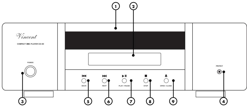
1. Display
The display shows track number, elapsed playing time and other information.
2. Disc tray
This drawer can be opened or closed to insert CD's with the button "▲ OPEN/CLOSE" (9)(24).
3. POWER
This is the main power switch for turning on and off the device. When switched off, the device is not disconnected from the mains and reacts to a signal at the connector "POWER CONTROL" (12).
4. PROTECT indicator LED
This LED is illuminated while after switching on the protection circuit is active.
5. BACK
Button for going back one track.
6. NEXT
Button for going forward one track..
7. II PLAY/PAUSE
Button for starting or interrupting the playback of the CD.
8. STOP
Stops the current playback of a CD or switches from pause to the player's initial state.
9. ▲OPEN/CLOSE
Button for opening and closing the CD tray.
REAR VIEW
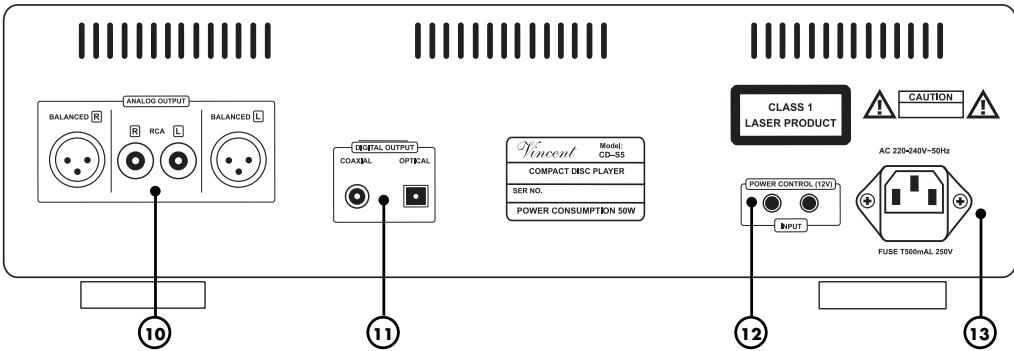
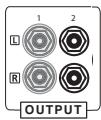
10. ANALOG OUTPUT:
analogue audio signal outputs
Either one of the RCA connector pairs or the XLR sockets ("BALANCED") are connected to the relevant input of the amplifier, preamplifier etc. It is not necessary to also connect one of the digital signal outputs (11).
11.DIGITAL OUTPUT:
digital audio signal outputs
If the amplifier, receiver or preamplifier is equipped with a digital coaxial or optical digital input connector, the relevant CD player signal output may be connected to this. It is not necessary to connect an analogue (10) and a digital signal output (11) at the same time.
12. POWER CONTROL (12V): ON/OFF control
These jack connectors (3,5mm) receive and forward the signal for the standby control (12V Trigger).
13. AC power connector and fuse holder
To establish the power supply, connect the plugs of the power cable to the device and to a wall power outlet. The small plastic housing beneath the plug opening holds the fuse. Refer to the security precautions.
REMOTE CONTROL
Point the front of the remote control directly at the front of the appliance, making sure there are no objects between the remote control and the appliance.
The distance between the remote control and the appliance should not be more than 7m as the reliability of the remote control is affected beyond this range.
Make sure that you do not point the remote control at an angle to the appliance, as beyond an angle of ± 30^ to the centre axis the appliance may not respond as well to the remote control. Change both batteries if the distance at which the remote control can be used effectively decreases.
BATTERIES
Using batteries
Handling batteries incorrectly can cause battery acid to escape or an explosion in extreme cases. The batteries must be correctly inserted taking note of the polarity, which is marked in the inside of the battery compartment.
In order to make full use of the batteries' life, do not mix new and used batteries. Make sure that you insert batteries of the same type.
Some batteries are rechargeable, others are not however. Take note of the precautions and instructions that are included on all batteries.
Remove the batteries if the remote control is not going to be used for a long time.
Under no circumstances must batteries be short-circuited, taken apart or heated up.
For environmental reasons, used batteries should be disposed of in accordance with local environmental regulations and not put with domestic waste.

Only use AAA (LR3) size batteries.
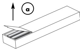
Changing/Inserting batteries:
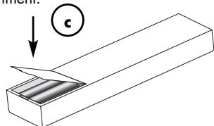
a) Open and remove the battery compartment lid of the remote control by tugging sharply on the fishplate on the edge of the remote control. The battery compartment lid is held in place magnetically, there is no need to loosen the screws!
b) If necessary, remove used batteries and insert new ones correctly as shown by the diagram in the battery compartment.
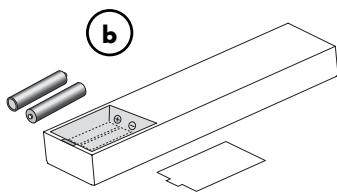
c) Put the compartment cover back on and close the battery compartment.
BUTTONS OF THE REMOTE CONTROL
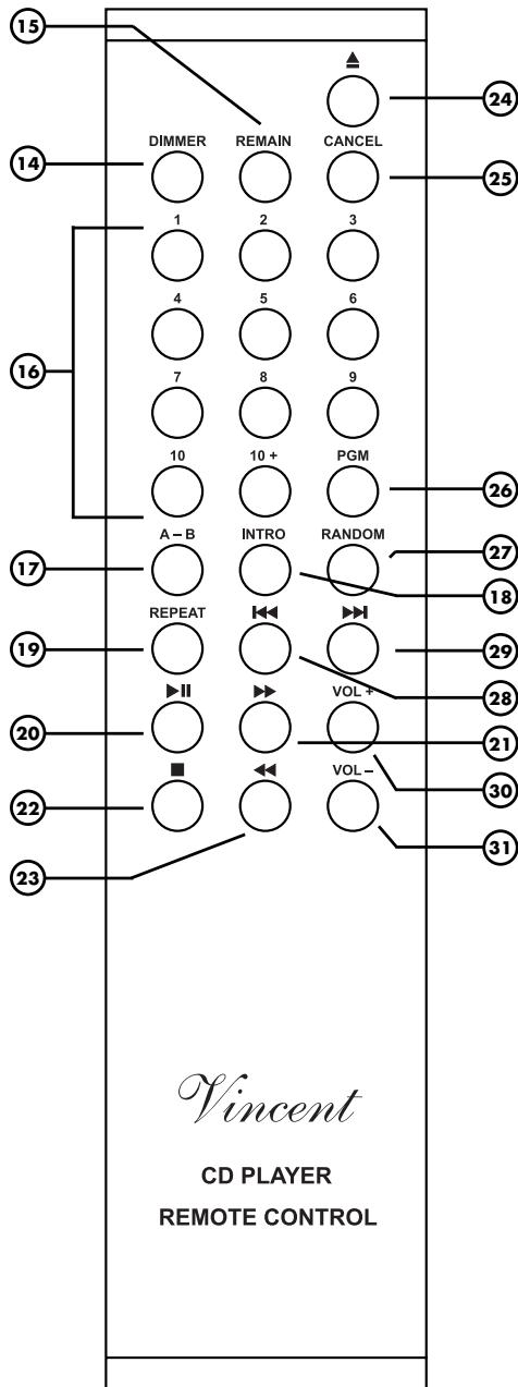
BUTTONS OF THE REMOTE CONTROL
14. DIMMER
Brightness adjustment for the display (1) on the front of the device.
15. REMAIN
Allows the remaining playing time of the current track or the remaining playing time of the CD to be displayed.
16. Number buttons:
You can choose tracks directly with these buttons or select them when programming a playing sequence (26).
17. A-B
Allows repeated playback of a selected section within a track.
18. INTRO
All tracks on the CD are played for 10 seconds one after the other.
19. REPEAT
Repetition of the individual track or of the entire CD.
20. II (PLAY/PAUSE)
CD playing can be started, briefly interrupted and resumed with this button.
21. (Fast forward)
You can wind forward quickly during playing with this button.
22. (STOP)
This button stops playing the current CD or ends the "PAUSE".
23. (Fast back)
You can wind backwards quickly during playback with this button.
24. (OPEN/CLOSE)
Button for opening and closing the CD compartment.
25. CANCEL
Deletes the track programming set up with "PGM".
26.PGM
You can specify (program) the order of playback of the tracks with this button.
27. RANDOM
For activating and deactivating random playing of the CD tracks.
28. (BACK)
Press this button to go back to a previous track in the sequence during playing.
29. (NEXT)
Press this button to go forward to a later track in the sequence during playing.
30. VOL+
Increases the output level of the analogue signal outputs "ANALOG OUTPUT" (10).
31. VOL-
Reduces the output level of the analogue signal outputs "ANALOG OUTPUT" (10). Only in few cases the "VOL" setting must be changed after setup of the player to a volume other than the maximum "26" to suit the device connected to these outputs.
INSTALLATION
Set up the cable links in a sequence as follows. Connect the power cable between device and power supply only after all other connections have been made.

DURING INSTALLATION PLEASE OBSERVE THE FOLLOWING ADVICE:

Protective caps
Prior to the first installation the protective plastic caps must be removed from all the connections used at the rear of the unit.
RCA connections
Mechanically identical RCA
plugs are available for analogue and digital outputs. Make sure that you do not get these connections confused during installation!
Make sure that you do not mix up the analogue connectors for right and left. The RCA plugs for these are mostly colour coded as follows: red for the right channel, black or white for the left channel.
Cable connections
Make sure that all plugs fit tightly. Inadequate connections can cause noise interference, failures and malfunctions.

- wrong -

- correct -
XLR connections
Note that European and US XLR signal use is different. This Vincent device uses the European system in accordance with Standard AES14-1992 of the Audio Engineering Society. The structure of the cable is in any event the same. Provided both connected devices meet the same standard, the signal connection is correct. This is always the case if both were manufactured by Vincent. If two devices with different standards are connected, the signal will then be inverted. In this case the signal use on one side of the connection must be changed. Your specialist dealer will assist you with this.
1.US System (Pin 2 = COLD, Pin 3 = HOT)
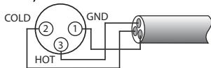
- European System (Pin 2 = HOT, Pin 3 = COLD)
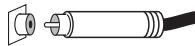
Optical Connection
The dust cap protecting the optical digital input should only be removed
if a cable is inserted. After a connection is removed from this input, the cap should be replaced.
Cables
To make the most of the components' sound potential, only high quality loudspeakers and connecting cables, for example Vincent cables, should be used. Your local stockist will be glad to advise you about this.
Check that the electricity supply to your home is appropriate to the device. The required voltage and frequency can be read on the back of the device beside the socket for the mains. If the electricity supply is appropriate, push the inlet connector of the supplied mains cable firmly into socket for the mains on the back of the device (12). Connect the other end of the mains cable to a mains socket.
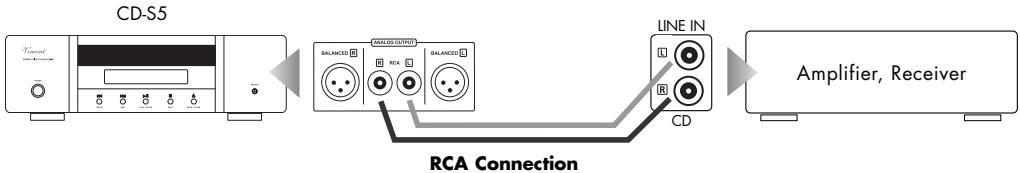
CONNECTION TO AMPLIFIER, RECEIVER OR PREAMPLIFIER
The CD-S5 has two analogue signal outputs and two digital output connections on the back of the device. The signal from the integrated D/A converter can be input to a traditional analogue audio component (amplifier) via the analogue outputs (10). On the digital outputs (11) there is a digital output audio signal which can be processed by external D/A converters or digital processors.
Only one of the four outputs needs to be connected to play CDs. Select the appropriate connection between the CD player and your amplifier, preamplifier, receiver or converter. Bear in mind when doing this that the special sound qualities of the player's Class A output amplifier stage will only be exploited if one of the analogue outputs (10) is used to output the music signal.
Use of the analogue output with RCA connectors
This is where the stereo audio signal converted to analogue by the high quality integrated D/A converter and amplified by the Class A stage is output. A RCA cable is required for connection to an amplifier. Connect the RCA connectors "L" and "R" in the field "ANALOG OUTPUT RCA" (10) with the left and right audio connections of the amplifier input (standard high level input) which is usually labelled "CD," "LINE IN" or "FRONT R/L".
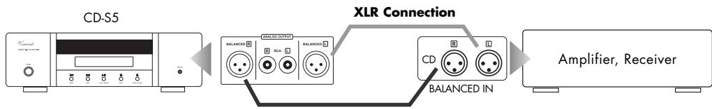
Use of the analogue output with XLR connector
This is where the stereo audio signal converted to analogue by the high quality integrated D/A converter and amplified by the Class A stage is output symmetrically. Two XLR cables are required for connection to an amplifier. Connect the XLR connectors "L" and "R" in the field "ANALOG OUTPUT XLR" (10) with the left and right connectors of the XLR amplifier input which is usually labelled "CD," "XLR IN," "BALANCED IN" or "FRONT R/L".
CONNECTION TO AMPLIFIER, RECEIVER OR PREAMPLIFIER
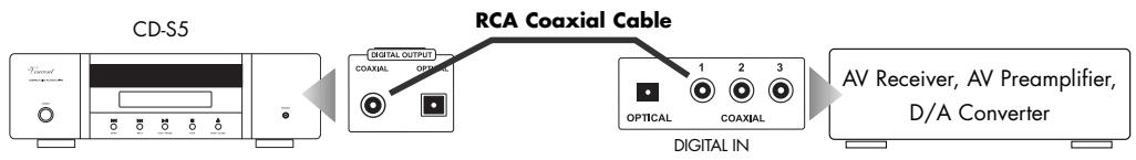
Use of the coaxial digital output
This output emits the music signal as a digital S/PDIF audio signal (PCM). The connection is only required if an external D/A converter is to be used or the player is to be connected to the coaxial digital audio input of an AV receiver or an AV preamplifier. To make the connection you need a coaxial cable with 75 characteristic impedance and with a RCA connector on both sides, which is not supplied with the device. Connect the connector "DIGITAL OUTPUT COAXIAL" (11) of the device to the digital input socket of the amplifier which is usually labelled "DIGITAL IN" or "COAXIAL INPUT". The best sound is obtained in most cases by connection with an analogue output (10).
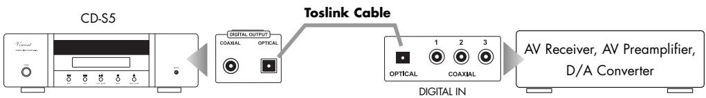
Use of the optical digital output
This output emits the music signal as a digital S/PDIF audio signal (PCM). The connection is only required if an external D/A converter is to be used or the player is to be connected to the optical digital sound input of an AV receiver or an AV preamplifier. To make the connection you need a Toslink cable (fibre optic cable) which is not supplied with the device. Connect the connector "DIGITAL OUTPUT OPTICAL" (11) of the device to the amplifier's digital input socket which is normally labelled "DIGITAL IN" or "OPTICAL INPUT". The best sound is obtained in most cases by connection with an analogue output (10).
CONNECTIONS FOR THE STANDBY CONTROL (POWER CONTROL)
Many AV-Systems consist of a multitude of individual components. To avoid the necessity of switching them on and off before and after every use, many manufacturers have equipped their devices with what is known as "POWER CONTROL" circuit or "TRIGGER". This kind of remote-controlled standby circuit is used primarily for preamplifier and power amplifiers. To employ these functions, direct or indirect cable connections must be made
between the preamplifier (or integrated amplifier) and all the devices which support this function. The "POWER CONTROL" function operates in such a way that each switching on or off of one device in the system (usually the preamplifier) automatically brings about the switching on or off of all the connected devices which support this function. Please keep in mind that all devices which respond to the power control are not disconnected from the mains
network when switched off. They are set to a stand-by state instead. For connecting cables, two-core cables with 3.5mm jack plugs (mono) are used. For each connection between two devices one of those cables is needed.
If the CD-S5 is to be switched on/off automatically with the preamplifier or integrated amplifier, then
the cable connections for power control described below must be made correctly and the "POWER" switch (3) must be moved to the switched off position.
If you don't wish to use this function or if the other components do not support it, all you have to do is leave out these cable connections.
The CD-S5 has two connectors for power control (12). One output on the transmitting device (integrated amplifier, preamplifier or a device that passes on the power control signal), usually labelled "POWER CONTROL" or "TRIGGER", must be connected to one of these two connectors (12). If the "POWER CONTROL" cable is connected to this device, the second jack connector serves to pass on the switch signal (for example to the main amplifier) or it remains free. This CD player cannot generate the switching signal for other components on its own!
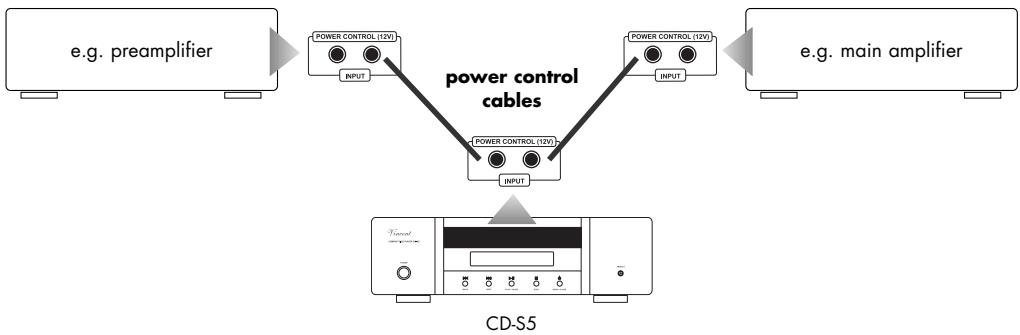
A theoretically infinite number of devices may be served with the switch impulses from a transmitting device. To this end, on most devices one of the two "POWER CONTROL" connectors may be used as a signal input and the other as a signal output. This method of passing on the signal via the devices' inputs and outputs and of thereby chaining them is also known as "daisy chaining".

Many devices which can be controlled by a switching signal (not preamplifiers or integrated amplifiers), have two terminals which do not differentiate between input and output. In this case either of the two can be selected. Even some devices that transmit the switch signal (preamplifiers and integrated preamplifiers) lack this marking. In this case it may be assumed that they both are signal outputs.
"POWER CONTROL" sockets of preamplifiers or integrated amplifiers must not be interconnected! All receiving devices must not be connected to more than one preamplifier or integrated amplifier (directly or indirectly)!
If a "POWER CONTROL" cable is connected to the back of the CD-S5 and the 12V switching signal is given, the main amplifier can no longer be switched off with the "POWER" button. If the power control function is not desired, the switch signal cables must therefore be removed!
OPERATING THE APPLIANCE
BASIC FUNCTIONS AND SETTINGS
| Operation | Button(s) | Description |
| Switch on and off | POWER (3) | The amplifier is switched on and off using this button at the front panel. When switched off the device is internally not separated from the AC power and reacts to a “POWER CONTROL” (12) switching signal. The appliance can not be switched on/off as long as a cable is connected to one of the jacks “POWER CONTROL”. As a precaution, before switching on, the volu- me setting of your system’s preamplifier should be reduced. |
| Change the level of the analogue audio outputs (10) at the rear panel | VOL+ (30) VOL- (31) | This function may only be activated with the remote control and only during playback. This control is to allow the adaptation of the player to the system (mainly the amplifier) and it must not be used to change the volume of the CD player in daily use. It is sufficient for almost all amplifiers/receivers/pre stages to put the setting to the maximum and to leave it there. A different value is only used if the CD player is much louder compared with the other sources at the amplifier/receiver or it is distorted (clipping). Hold down the “VOL+” button to raise the output level. Use the “VOL” to reduce it. The two- figure value of the volume appears in the display (1). The maximum signal level is reached with a setting of 26 and the minimum is at 00. This volume control changes the output level of all analogue outputs to the same extent. In order to decode HDCDs properly, this setting must be set to the maximum “26” when playing a HDCD! |
| Change the brightness of the front panel display | DIMMER (14) | This function can only be operated using the associated front panel button. When repeatedly pressed, the display (1) brightness is periodically reduced (1x), switched off (2x) and restored to the original, maximum brightness (3x). |
PLAYBACK FUNCTIONS
| Operation | Button(s) | Description |
| Start and pause playback | ►II (7)(20) PLAY/ PAUSE | This button, both on the front of the device and on the remote control, starts playing the inserted CD and the symbol “►” appears on the display (1) during play. If there is no CD inserted, “NO DISC” appears in the display and pressing the button has no effect. If the button is pressed again while a CD is playing, play will be interrupted at the current position. This “PAUSE” mode is indicated in the display by the symbol “■”. During the pause the disc continues to rotate and when the button is pressed play continues from this position. The “PAUSE” function should only be used for brief interruptions. |
| Insert/Change the CD | ▲ (9)(24) OPEN/ CLOSE | With this button you open and close the disc tray so that a CD can be inserted or removed. This button is located both on the front of the device and on the remote control. If the text “OVER” appears in the display (1), then the CD contains more than 16 tracks. Some of the tracks cannot then be shown in the display's music menu. |
OPERATING THE APPLIANCE
PLAYBACK FUNCTIONS
| Operation | Button(s) | Description |
| Direct selection of a track | Number keys(16) | You can start playing a track at any time by keying in the track number on the remote control. For numbers over 10, you must press the "+" button as often as necessary until it shows the relevant first figure of the number and then you key in the second figure. If there is no track of the keyed-in number on the CD, the player switches to "STOP" mode. If the player is paused, you cannot select any other track directly with the number buttons. |
| Stop playback | ■(8)(22)STOP | While a CD is being played, pressing this button stops the playing. If the player was in "PAUSE" mode, this mode will also be ended by pressing the "STOP" button. The total number of tracks on the CD and the total playing time appear in the display (1) again. This button is on both the front of the device and the remote control. |
| Skip to the following track | ▶(6)(29)NEXT | When this button is pressed while the CD is playing, the current track stops playing and the next track in the sequence begins to play. If this button is pressed in "STOP" mode, you can choose all the CD tracks one after the other starting from track 01. Playback can then be started again with the "PLAY/PAUSE" button (7)(20), with the "STOP" button (8)(22) the player goes back to "STOP" mode. This button is located both on the front of the device and on the remote control. |
| Skip to playback the previous track | ▶(5)(28)BACK | If this button is pressed once while the CD is playing, the current track stops and the actual track starts playing from the start again. Further pres-SES skip to playing the previous tracks in their playing sequence. If this button is pressed in the "STOP" mode, you can choose all the CD tracks in reverse order starting with the last track. Playback can then be started again with the "PLAY/PAUSE" button (7)(20). With the "STOP" button (8)(22) the player goes back to "STOP" mode. The button is located both on the front of the device and on the remote control. |
| Fast forward | ▶(21)(FAST FORWARD) | The track will be played at higher speed (fast forward) as long as you continue to hold down this button while the CD is playing. If the button is released, playback will continue at normal speed. If the CD play is stopped, then this button has no function. This play function too can only be used via the remote control. |
| Fast rewind | ▶(23)(FAST BACK) | The track will be played backwards at higher speed ("rewind") as long as you continue to hold down this button while the CD is playing. If the but-ton is released, play will continue at normal speed in a forward direction. If the CD playback is stopped, then this button has no function. This play function too can only be used via the remote control. |
OPERATING THE APPLIANCE
ADVANCED PLAYBACK FUNCTIONS
| Operation | Button(s) | Description |
| Indication of the remaining playing time | REMAIN (15) | After pressing this remote control key while the CD is playing, the rema- ning time of the current track will be shown (indicated by the text “REMAIN” in the display (1)). Pressing the key again switches the display to the remaining playing time of the entire CD or the entire program, with the display then showing “REMAIN ALL”. Pressing the key a third time switches back to the normal playing time display. |
| Switch between normal and random playback | RANDOM (27) | The function activated with this remote control button ensures that all the CD tracks are played in random order. This function cannot be used for playing a program set up with “PGM” (26). If this button is pressed during play or pause, the current track is stopped and the playing of all the CD tracks in random order begins. In the display, this play mode will be indica- ted by the text “RAN”. Pressing the “RANDOM” button again switches off random playing and playing will continue from the current position. |
| Switch between playing the content of the CD once, repeating an individ- dual track and repeating all the tracks on the CD | REPEAT (19) | If this button is pressed once while the CD is playing, the current track will be played over and over again when it has finished. In the display (1) this operation mode is indicated by the text “REPEAT 1”. If this button is pres- sed twice while the CD was playing, then the entire CD or the entire pro- gram will be played over and over again when it has finished. In the dis- play this operation mode is indicated by the text “REPEAT ALL”. A third press of the key switches this function off. The desired repeat mode can also be switched on even when play is stopped or for a selected pro- gram. The “REPEAT” button is only on the remote control. |
| Repeat a custom section of the track as an end- less loop | A-B (17) | While the CD is playing, the first press of this key marks the start of the section (A) and the second press marks the end of this section (B). As soon as both points are selected, the player continues to play the marked extract over and over again until the “A-B” key is pressed again or “STOP” (8)(22) is pressed. In the display (1) this play mode is indicated with the symbol “A ↔ B”. After the A-B playback has been stopped with the “STOP” key (8)(22), the marked points will be deleted. This play opti- on too can only be controlled via the remote control. |
| Play a short introduction of every track | INTRO (18) | You can press this remote control key if the beginning of every track is only to be played for a brief time. In this mode the first ten seconds of the track will be played then it will skip to the next track in the sequence. This functi- on is also known by the term “Intro Scan”. Even if a program has been set up for the play sequence (26), all the CD tracks will each be played once for a brief time after the “INTRO” key has been pressed. Pressing this key again ends the Intro Mode and continues playing the remaining section from the current position onwards. The text “INTRO” will be shown on the display (1) while the “Intro Sscan” is active. If this key is pressed during play or pause, the Intro Mode always starts with the first CD track. |
OPERATING THE APPLIANCE
ADVANCED PLAYBACK FUNCTIONS
| Operation | Button(s) | Description |
| Program the playback order | PGM (26)Number Keys (16) | With this function it is possible to set up a desired playing sequence of the CD tracks. This also allows you to play a smaller selection of your own choice from all the CD tracks. This programming can only be done with the remote control. The "program" is set up by the following procedure:Press the PGM button.Enter the numbers of all the desired tracks one after the other on the number pad (16) of the remote control. For track 10 use the "10" button. For all other two-figure track numbers first press the "+10" button as many times as necessary until the number of 10's is correct, then press the button for the last figure (for track 23 press the " +10" button twice and the "3" button once).To confirm the program press "STOP"(8)(22) or "PLAY/PAUSE"(7)(20).The "REPEAT" play function (19) can also be applied to the programmed track selection. You can see on the display (1) from the text "PGM" that a program is active. It is only if you press "CANCEL" (25), eject the CD or switch off the CD player that your own playing sequence is deleted. |
| Delete the selected playing sequence | CANCEL (25) | This button deletes a program set up with the "PGM" function (26). If the button is pressed during a pause, any created program will be deleted and you can continue to play the current track and the remaining CD tracks with "PLAY/PAUSE"(7)(20). Just as with the programming, this action may only be performed with the remote control. |
TIPS
Burn in/ Warm up
Your audio components need a certain time period until they reach maximum performance. The duration of this "warm up" time is very different for the various elements of your audio system. Higher and homogeneous sound quality is achieved while keeping the device switched on.
Your audio specialist dealer has enough experience to give you more information.
Net frequency noise
Some audio source devices may in combination with the amplifier cause a humming noise at power line frequency audible from your speakers. Usually, its volume varies with the volume setting of the amplifier. This is no sign of a defect or fault of your audio products but has to be eliminated. Generally, every wall-powered device connected to the ground wire of the power plug can cause this problem when connected to the amplifier.
Experience shows that this problem is mainly caused by antenna-connected components (as TV-sets or Tuners), personal computers, electrostatic loud
speakers, subwoofoers, record players or headphone amplifiers that are connected to the audio inputs of the amplifier. Another possible reason for humming noise is electromagnetic interference of other components' power supplies with pick-up systems of record players (change the place of the record player for a test).
In most electric devices the ground potentials of all signals are connected to each other at one central point, where they have one common connection. If the device uses the protective conductor of the wall outlet, the corresponding wire of the line cord is connected intractably to the metal housing of the device. This is the mostly the point where the central grounding point is attached to. By doing this the housing is able to shield all signals from external radiated noise. Some main amplifiers are equipped with a "Ground Lift"-switch. If it is activated, ground potential of the chassis and the protective ground wire are being separated from the central signal ground point. The protective ground wire keeps its function. Sometimes this helps prevent noise caused by errors in grounding.
If the problem occurs and cannot be solved by yourself your audio specialist dealer will help you.
SEARCH FOR ERRORS
| Symptom | Possible Cause | Countermeasure |
| Unit does not work after pressing the power button | Mains cable is not connected to a suitable mains wall outlet.Mains cable has not been firmly inserted into wall power socket and the device's socket. Otherwise it may be defective.Unit fuse or unit is defective. | Connect to a functioning socket using a suitable mains voltage Check the power cable. If necessary, exchange it with a suitable mains cable and push its plug firmly into wall socket and the device's power connector.Contact your dealer. |
| The unit cannot be switched off | A device connected to the “POWER CONTROL” input transmits the switching signal (12V). | Switch off the device that controls the swit- ching on/off of the system (usually preampli- fier or integrated amplifier). If the power con- trol function is not desired, remove all the cables from the “POWER CONTROL” connectors (12). |
| An inserted disc is not read | An unsuitable data medium e.g. a DVD or a data CD-R has been inserted.Perhaps the CD is dirty or scratched.The CD was not inserted with the printed side up.A CD-R was written at too great a speed. | The relevant disc cannot be played with this player.Clean the CD and try it again.Insert the CD in the correct position.The disc cannot be played. |
| Play does not start after pressing“PLAY/PAUSE”(7)(20) | If there is a large major in the ambient tempera-ture, moisture may have precipitated in the player's drive. | After 1-2 hours the moisture should have evaporated and the CD will play again. |
| No sound on both channels although the unit is ready for use (front panel dis-play (1) is functional) | A wrong input channel or a volume setting too low has been selected at the amplifier.The appropriate audio output of the player is not connected or not correctly connected with the desired input connector of the receiver/amplifier.CD playing has not been started.Output level “VOL” (30)(31) has been set too low with the remote control. | Check and correct the connections and set- tings.Create an audio connection between the CD player and the receiver/amplifier as descri- bed in the “Installation” section.Start playback with “PLAY/PAUSE” (7)(20). Carefully increase the output level. |
| Front panel display does not work | It has been switched off before using “DIMMER” (14). | Press the button “DIMMER” (14) one more time. |
SEARCH FOR ERRORS
| Symptom | Possible Cause | Countermeasure |
| No audio playback on one channel | One of the signal cables between CD player and amplifier input has not yet been plugged in or is defective. | Check the cable connections, tighten them if necessary. |
| One of the loudspeaker cables or (if you are using pre & main amplifiers) one of the signal cables between pre and main amplifier is not correctly connected or is faulty. | Check all the connections of the amplifiers and whether the loudspeakers are working. | |
| Poor sound quality | Analogue audio outputs of the CD player are connected to phono inputs of the amplifier/receiver/preamplifier. | Use a normal high level input ("CD" or "LINE IN") on these devices. |
| The cable connections are not tight, the connectors are dirty or a cable is defective. | Check the cables and cable connections. | |
| The remote control cannot perform any functions | No batteries inserted in the remote control, batteries are not inserted correctly or are depleted. | Check and replace the batteries if necessary. |
| The line-of-sight between the remote control and the unit is obstructed, the range was exceeded or the hand unit was operated from a position too far to one side. | Try to point the remote control at the front of the unit only when the sight-line is clear, within a 7-metre distance and, if possible, facing the unit. | |
| The unit is not switched on. | Switch on the unit. | |
| Humming low frequency noise is audible, even as no audio source is playing back | See section "Net frequency noise" in the chapter "Tips". | See section "Net frequency noise" in the chapter "Tips". |
TECHNICAL SPECIFICATIONS
D/A converter: 24 bit / 192 kHz
Frequency response: 10Hz - 20kHz (± 0.5dB)
Total Harmonic Distortion: < 0.003 %
Signal to Noise Ratio: >95 dB
Dynamic Range: >100 dB
Output impedance: 600Ω
Audio Output Voltage: 2.5 V
Channel Separation: > 90 dB
Outputs: 1 × XLR stereo, 1 × RCA stereo,
1x digital coaxial, 1x digital optical
AC power connection type: 220V - 240V / 50 Hz max. 25W
Dimensions (WxHxD): 430 × 135 × 330 ~mm
Weight: 10 kg
Colour: black / silver
GLOSSARY
Audio Sources/Source devices
These are the components of your HiFi system and all other appliances, whose sound you want to hear over the system and are thus connected to the pre-amplifier, amplifier or receiver. This includes CD players, DVD players, tuners (radians), cassette players, DAT recorders, personal computers, record players, portable audio devices and many more.
Dynamic
The volume difference between the quietest and the loudest sounds possible in audio signals (without distortion or transition to noise).
Input sensitivity
Term for the smallest average (RMS) input voltage which causes the maximum output power at the maximum volume setting on the amplifier. Examples: 100mV to 500mV (Millivolts) on high level inputs, 2mV to 5mV on the phono MM input or 0.1mV to 0.5mV on the phono MC input.
dB-Level
This is a way of describing any physical quantity; it is a common measurement for signal voltages and the volume. It is given in decibels (dB). Alternating signal voltages below 1V (RMS) are described as "line level" voltages, which are suitable as music signals for amplifier inputs. Inputs on amplifiers (mostly represented by RCA sockets), which are designed for signals on the CD player, tape recorder, DVD player etc. are also referred to as "line level inputs" or "high-level inputs". Those signal inputs must not be confused with inputs that accept preamplified signals.
RCA
RCA is the American name for coaxial RCA connectors and sockets, originally the abbreviation for "Radio Corporation of America", the name of a United States company. Both the plug and cable consist of a rod-shaped inner lead and a cylindrical-shaped outer lead. This enables a mono audio signal or a video signal to be transmitted. Compared to the XLR plug connector, this type of connection is also called "unbalanced signal connection".
XLR
Also: "Symmetrical Connection" or "balanced". A plug-and-socket connection for audio devices. It is round (with approx. 1.5cm in diameter) and has 3 contacts/pins. XLR is an alternative connection to RCA used to transmit NF-Signals in professional audio equipment. The advantage is one additional transmission path for the same but phase inverted signal. If the receiving device can process this, all inducted noise received in the cable screen can be eliminated. The signal voltage level used for this type of transfer is higher, so it is a more robust less sensitive signal path.
CONSIGNES DE SECURITE
- Système US (Pin 2 = COLD, Pin 3 = HOT)
1x XLR stereo, 1x RCA stereo,
Please keep the receipt, store it together with this manual. The receipt is your proof for the beginning of the warranty period. Note the serial number in the following box, you can read it from the rear side of the device.