
SR 40 - Wireless transceiver AKG - Free user manual and instructions
Find the device manual for free SR 40 AKG in PDF.

| Product type | Non-diversity stationary receiver for WMS 40 system |
| Brand | AKG |
| Model | SR 40 |
| Dimensions (W x D x H) | 235 x 142 x 43 mm |
| Net weight | 470 g |
| Power supply | 12-16 V DC via supplied power adapter |
| Power consumption | 95 ±15 mA |
| Carrier frequency range | 710 - 865 MHz (depending on version) |
| Modulation | FM |
| Audio bandwidth | 40 - 20,000 Hz |
| Frequency stability | ±15 kHz (-10°C to +50°C) |
| Distortion factor (1 kHz) | typ. 0.8% |
| Compander | Yes |
| Signal-to-noise ratio | typ. 103 dB(A) |
| Input sensitivity | typ. -95 dBm |
| Squelch threshold | -70 to -98 dBm (adjustable) |
| Audio outputs | XLR balanced (MIC OUT) and 6.3 mm unbalanced jack (LINE OUT), adjustable mic to line level, max. 2 V eff. |
| Antenna | Fixed front UHF antenna |
| Indicators | Power LED (POWER) and RF LED (received signal) |
| Controls | Volume (output level) and Squelch (silencing threshold) |
| Color code | Corresponds to carrier frequency (see label) |
| Included accessories | 12 V DC power adapter, screwdriver |
| Optional accessories | 19" rack mount kit RMU60, CH40 case |
| Maintenance and cleaning | Soft cloth slightly damp (no aggressive products) |
| Safety | Do not expose to moisture, do not open, use only the supplied adapter, unplug if not in use |
| Compliance | EN60065, EN301 489-9, EN300 422-2 |
Frequently Asked Questions - SR 40 AKG
User questions about SR 40 AKG
0 question about this device. Answer the ones you know or ask your own.
Ask a new question about this device
Download the instructions for your Wireless transceiver in PDF format for free! Find your manual SR 40 - AKG and take your electronic device back in hand. On this page are published all the documents necessary for the use of your device. SR 40 by AKG.
USER MANUAL SR 40 AKG
H A Harman International Company
AKG Acoustics GmbH
Bodenseestraße 228, D-81243 Munchen/GERMANY, Tel: (+49 89) 87 16-0, Fax: (+49 89) 87 16-200, www.arkg-acoustics.de, e-mail: info@arkg-acoustics.de
AKG ACOUSTICS, U.S.
914 Airpark Center Drive, Nashville, TN 37217, U.S.A., Tel: (+1 615) 620-3800, Fax: (+1 615) 620-3875, www.akgusa.com, e-mail: akgusa@harman.com
For other products and distributors worldwide see our website: www.akg.com
User Instructions. p. 10
Please read the manual before using the equipment!
DECLARATION OF CONFORMITY
Document No.290 / 02 - 2002
replaces No. 179 / 06 - 2000
Type of Product: Wireless Microphone System, Stationary Receiver
Brand, Model No.: SR 40
Drawing-No.: 760. X 0003
Manufacturer: AKG Acoustics GmbH
A-1230 Wien, Lemböckgasse 21 - 25
AUSTRIA
We declare that the above mentioned product is in conformity with the following European Directive:
No. 99/5 EC;
Radio Equipment and
Telecommunications Terminal Equipment
The conformity is achieved by fulfilling the following European Standard(s):
EN 301489-9 v.1.1.1 (09-2000); I-ETS 300422:1995; IEC 60065:1998
Product examination was carried out by:
Manufacturer's Signature: unlaids
Managing Director
Dr. Hugo Lenhard-Backhaus
This declaration certifies the accordance with the above mentioned EC-Directive but does not assure certain attributes of the product.
SR 40

SR 40
Technische Änderungen vorbehalten. Specifications subject to change without notice. Cesarektiques sont susceptibles de modifications. Ci sienviamo il dirito di effettua modifiche tecnique. Nos reservamos el derecho de introducir modalazioni tecnicas. Especificaue sujetas a mudanzas sem aviso previo.

AKG Acoustics GmbH
Lembockgasse 21-25, P.O.B. 158, A-1230 Vienna/AUSTRIA, Tel: (+43 1) 86 654-0", Fax: (+43 1) 86 654-7516, www.aqk.com, e-mail: sales@aqk.com
H A Harman International Company
AKG Acoustics GmbH
Bodensestraße 228, D-81243 München/GERMANY, Tel: (+49 89) 87 16-0, Fax: (+49 89) 87 16-200, www.aqk-acoustics.de, e-mail: info@aqk-acoustics.de
AKG ACOUSTICS, U.S.
914 Airpark Center Drive, Nashville, TN 37217, U.S.A., Tel: (+1 615) 620-3800, Fax: (+1 615) 620-3875, www.akgusa.com, e-mail: akgusa@harman.com
For other products and distributors worldwide see our website: www.akg.com
User Instructions. p. 10
Please read the manual before using the equipment!
DECLARATION OF CONFORMITY
Document No.290 / 02 - 2002
replaces No. 179 / 06 - 2000
Type of Product: Wireless Microphone System, Stationary Receiver
Brand, Model No.: SR 40
Drawing-No.: 760. X 0003
Manufacturer: AKG Acoustics GmbH
A-1230 Wien, Lemböckgasse 21 - 25
AUSTRIA
We declare that the above mentioned product is in conformity with the following European Directive:
No. 99/5 EC;
Radio Equipment and
Telecommunications Terminal Equipment
The conformity is achieved by fulfilling the following European Standard(s):
EN 301489-9 v.1.1.1 (09-2000); I-ETS 300422:1995; IEC 60065:1998
Product examination was carried out by:
Manufacturer's Signature: unlaids
Managing Director
Dr. Hugo Lenhard-Backhaus
This declaration certifies the accordance with the above mentioned EC-Directive but does not assure certain attributes of the product.
SR 40


1 Safety and Environment. 11
1.1 Safety 11
1.2 Environment. 11
2 Description 11
2.1 Introduction 11
2.2 Unpacking 12
2.3 Optional Accessories 12
2.4 SR 40 Receiver 12
3 Setting Up 13
3.1 Placing the Receiver 13
3.2 Mounting the Feet on the Receiver 13
3.3 Rack Mounting a Single Receiver. 13
3.4 Rack Mounting Two Receivers Side by Side. 13
3.5 Connecting the Receiver to a Mixer 14
3.6 Connecting the Receiver to an Amplifier 14
3.7 Connecting the Receiver to Power. 14
3.8 Before the Soundcheck 14
4 Cleaning. 15
5 Troubleshooting 15
6 Specifications 16
FCC Statement
This equipment has been tested and found to comply with the limits for a Class B digital device, pursuant to Parts 74, 15, and 90 of the FCC Rules. These limits are designed to provide reasonable protection against harmful interference in a residential installation. This equipment generates, uses, and can radiate radio frequency energy and, if not installed and used in accordance with the instructions, may cause harmful interference to radio communications. However, there is no guarantee that interference will not occur in a particular installation. If this equipment does cause harmful interference to radio or television reception, which can be determined by turning the equipment off and on, the user is encouraged to try to correct the interference by one or more of the following measures:
Reorient or relocate the receiving antenna.
- Increase the separation between the equipment and the receiver.
- Connect the equipment into an outlet on a circuit different from that to which the receiver is connected.
- Consult the dealer or an experienced radio/TV technician for help.
Shielded cables and I/O cords must be used for this equipment to comply with the relevant FCC regulations.
Changes or modifications not expressly approved in writing by AKG Acoustics may void the user's authority to operate this equipment.
This device complies with Part 15 of the FCC Rules. Operation is subject to the following two conditions: (1) this device may not cause harmful interference, and (2) this device must accept any interference received, including interference that may cause undesired operation.
- Do not spill any liquids on the equipment and do not drop any objects through the ventilation slots in the equipment.
- The equipment may be used in dry rooms only.
- The equipment may be opened, serviced, and repaired by authorized personnel only. the equipment contains no user-serviceable parts.
- Before connecting the equipment to power, check that the AC mains voltage stated on the supplied AC adapter is identical to the AC mains voltage available where you will use the equipment.
- Operate the equipment with the supplied 12-V AC adapter. Using adapters with a DC output and/or a different output voltage may cause serious damage to the unit.
- If any solid object or liquid penetrates into the equipment, shut down the sound system immediately. Disconnect the AC adapter from the power outlet immediately and have the equipment checked by AKG service personnel.
- If you will not use the equipment for a long period of time, disconnect the AC adapter from the power outlet. Please note that the equipment will not be fully isolated from power when you set the power switch to OFF.
- Do not place the equipment near heat sources such as radiators, heating ducts, or amplifiers, etc. and do not expose it to direct sunlight, excessive dust, moisture, rain, mechanical vibrations, or shock.
- To avoid hum or interference, route all audio lines, particularly those connected to the microphone inputs, away from power lines of any type. If you use cable ducts, be sure to use separate ducts for the audio lines.
- Clean the equipment with a moistened (not wet) cloth only. Be sure to disconnect the AC adapter from the power outlet before cleaning the equipment! Never use caustic or scouring cleaners or cleaning agents containing alcohol or solvents since these may damage the enamel and plastic parts.
11.Use the equipment for the applications described in this manual only. AKG cannot accept any liability for damages resulting from improper handling or misuse. - The AC adapter will draw a small amount of current even when the equipment is switched off. To save energy, disconnect the AC adapter from the power outlet if you will leave the equipment unused for a long period of time.
- When scrapping the equipment, separate the case, circuit boards, and cables, and dispose of all components in accordance with local waste disposal rules.
1.1 Safety
1.2 Environment
2 Description

Thank you for purchasing an AKG product. This Manual contains important instructions for setting up and operating your equipment. Please take a few minutes to read the instructions below carefully before operating the equipment. Please keep the Manual for future reference. Have fun and impress your audience!
2.1 Introduction
2.2 Unpacking
1 SR 40
1 AC adapter, 12 V DC
1 screwdriver
Please check that the packaging contains all system components as listed above. If anything is missing, please contact your AKG dealer.
2.3 Optional Accessories
RMU 60 19" rack mounting kit for 2 SR 40 receivers
CH 40 plastic carrying case for one complete WMS 40 system.
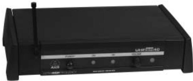
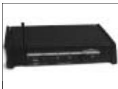
2.4 SR 40 Receiver
The SR 40 is a stationary non-diversity receiver for use with all WMS 40 transmitters. The SR 40 operates on one fixed, quartz stabilized frequency in the 710 MHz to 865 MHz UHF carrier frequency range and features a rack-mount case.
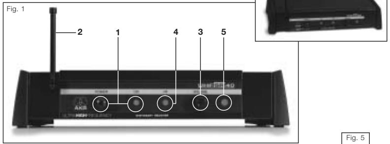
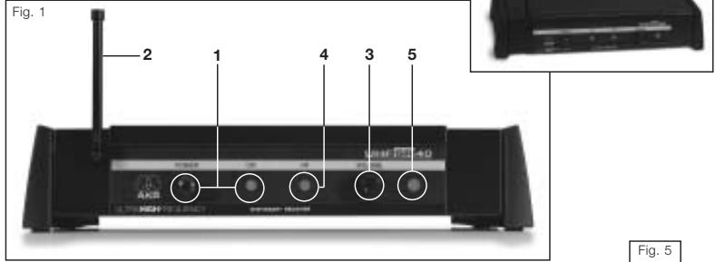
2.4.1 Front Panel Controls
Refer to fig. 1.
1 POWER: On/off pushbutton switch and indicator LED.
2 Antenna: Fixed-length UHF antenna permanently mounted on the front panel.
3 VOLUME: This rotary control adjusts the SR 40's output level from microphone to line level for matching to the input sensitivity of your mixer or amplifier.
4 RF: This LED lights to indicate that signal is being received. If no signal is received or the squelch is on, the RF LED goes out and the audio output is muted.
5 Color Code: The color indicates the carrier frequency of your receiver. Transmitters tuned to the same frequency are marked with identical colors.
Table 1: WMS 40 system color code.
| US54: | 710.400 MHz | reddish brown |
| US58: | 734.600 MHz | purple |
| KR3: | 745.650 MHz | mint green |
| KR4: | 750.900 MHz | dark gray |
| EU62: | 802.525 MHz | Bordeaux red |
| EU63: | 812.800 MHz | yellow |
| UK69A: | 854.900 MHz | violet |
| UK69B: | 858.200 MHz | green |
| ISM1: | 863.100 MHz | melon yellow |
| ISM2: | 864.375 MHz | gray |
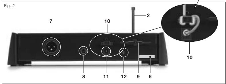
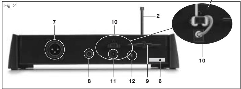
2.4.2 Rear Panel Controls
Refer to fig. 2.
6 Carrier Frequency Label: A label indicating the carrier frequency and approval marks of your receiver is affixed to the rear panel of the receiver.
7 MIC OUT: Balanced 3-pin XLR audio output for connecting to, e.g., a microphone input on a mixing console.
8 LINE OUT: Unbalanced audio output on a 1/4" mono jack for connecting to, e.g., a guitar amplifier.
9 Screwdriver for adjusting the SQUELCH control on the receiver and the GAIN control on the bodypack transmitter.
10 Strain Relief for the feeder cable of the supplied AC adapter.
11 DC IN: Input connector for the supplied AC adapter.
12 SQUELCH: The squelch circuit switches the receiver off if the
received signal is too weak, in order to suppress the related noise or the residual noise of the receiver while the transmitter is off. Set the SQUELCH control to minimum before first switching the receiver on. (For details, refer to section 3.8.)
3 Setting Up

Prior to setting up your WMS 40, check that the transmitter and receiver are tuned to the same frequency. The easiest way to do this is to compare the color codes on the transmitter and receiver.
Reflections off metal parts, walls, ceilings, etc. or the shadow effects of musicians and other people may weaken or cancel the direct transmitter signal.
For best results, place the receiver as follows:
- Place the receiver near the performance area (stage). Make sure, though, that the transmitter will never get any closer to the receiver than 10 ft (3 m). Optimum separation is 16 ft. (5 m).
- Check that you can see the receiver from where you will be using the transmitter.
- Place the receiver at least 5 ft. (1.5 m) away from any big metal objects, walls, scaffolding, ceilings, etc.
You can either use the receiver freestanding or mount it in a 19" rack using the optional RMU 60 rack mounting kit.
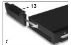
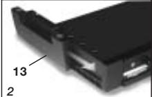
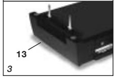
- Place the receiver with the bottom panel up on a flat surface.
- Slide the two supplied side panel moldings (13) with the rubber feet facing up into the fixing rails on both sides of the receiver from rear to front.
- Use the supplied Phillips screws to fasten the side panel moldings (13) to the receiver.
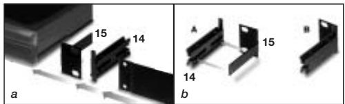
- Place a clamping slide (14) on each rack ear (29), checking that the pegs on the clamping slides (14) engage in the fixing holes on the rack ears (29).
- Slide the clamping slides (14) and rack ears (15) into the fixing rails on both sides of the receiver from rear to front.
- Tighten the two Phillips screws in the clamping slides (14) CW to fix the rack ears (15) on the receiver.
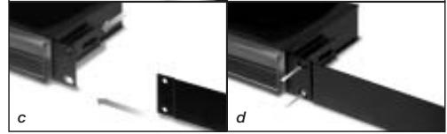
- Use the supplied screws to fix the supplied blank panel to the left or right rack ear (29).
- Use the supplied installation screws to install the receiver in the rack.
- Fix one rack ear (15) to the outside panel of each receiver referring to steps 1 through 3 above.
- Insert a clamping slide (14) with no rack ear (15) into the fixing rails on the INSIDE PANEL of one receiver.
Important!
Refer to Table 1 on page 12.
3.1 Placing the Receiver
3.2 Mounting the Feet on the Receiver
Refer to Fig. 3.
3.3 Rack Mounting a Single Receiver
Refer to figs.
4a and 4b.
Refer to fig. 4c.
Refer to fig. 4d.
3.4 Rack Mounting Two Receivers Side by Side
| 3. Insert the receiver with the clamping slide (14) on its inside panel into the fixing rails on the inside panel of the other receiver. 4. Tighten the two Phillips screws in the inside clamping slide (14) CW to connect the two receivers. 5. Use the supplied installation screws to install the receivers in the rack. | |
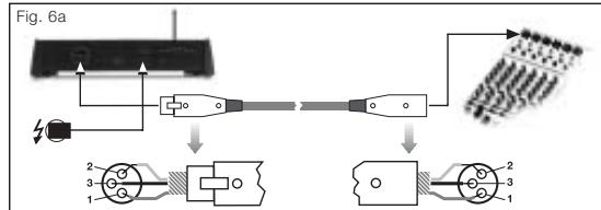
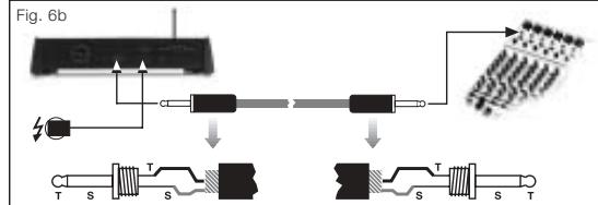
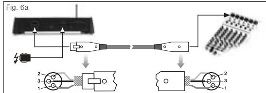
| 3.5 Connecting the Receiver to a Mixer Refer to fig. 6a. | You can connect the receiver to a mixer in one of two ways: A. Use a standard XLR cable to connect the MIC OUT connector (7) on the receiver rear panel to a balanced XLR microphone input on the mixer. Turn the VOLUME control (3) on the receiver all the way CCW to set the receiver output to microphone level. B. Use a standard 1/4" jack cable to connect the LINE OUT jack (8) on the receiver rear panel to an unbalanced 1/4" line input jack on the mixer. Turn the VOLUME control (3) on the receiver all the way CW to set the receiver output to line level. |
| Refer to fig. 8b. | |
| Important! | Never use the two audio outputs simultaneously! This may cause signal loss or increased noise. |
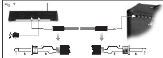
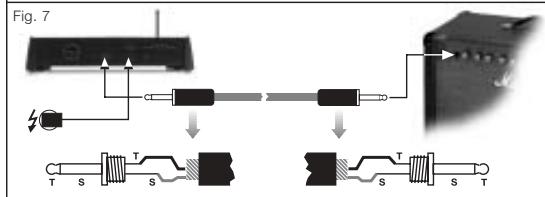
| 3.6 Connecting the Receiver to an Amplifier Refer to Fig. 7. | 1. Use a standard 1/4" jack cable to connect the LINE OUT jack (8) on the receiver rear panel to an unbalanced 1/4" line input jack on the amplifier. 2. Turn the VOLUME control (3) on the receiver all the way CW to set the receiver output to line level. |
| 3.7 Connecting the Receiver to Power Refer to Fig. 5. | 1. Point the antenna (2) upward. 2. Set the SQUELCH control (12) fully CCW. 3. Check that the AC mains voltage stated on the supplied AC adapter is identical to the AC mains voltage available where you will use your WMS 40. Using the AC adapter with a different AC voltage may cause irreparable damage to the unit. 4. Plug the feeder cable on the supplied AC adapter into the DC IN socket (11) on the receiver. 5. Bend part of the feeder cable into a small bight, pass the bight through the strain relief (10) from above, and place the end of the bight snugly against the hook on the strain relief (10). Tighten the cable. 6. Plug the AC adapter into a convenient power outlet. 7. Press the POWER switch (1) to switch power to the receiver ON. |
| 3.8 Before the Soundcheck | 1. Move the transmitter around the area where you will use the system to check the area for "dead spots", i.e., places where the field strength seems to drop and reception deteriorates. If you find any dead spots, try to eliminate them by repositioning the receiver. If this does not help, avoid the dead spots. 2. If unwanted noise becomes audible, turn the SQUELCH control (12) on the receiver CW just enough to suppress the noise. The RF LED (4) will extinguish every time the squelch mutes the audio output of the receiver. |
Never set the squelch threshold higher than absolutely necessary. The higher the squelch threshold, the lower the sensitivity of the receiver and thus the usable range between transmitter and receiver.
Important!
- The RF LED (4) on the receiver going out means no signal is being received or the squelch is active.
Remedies: Switch power to the transmitter ON, move closer to the receiver, or turn the SQUELCH control (12) CCW to the point that the RF LED (4) will come back on.
4 Cleaning

Use a soft cloth moistened with water to clean the receiver surfaces.
5 Troubleshooting

| Problem | Possible Cause | Remedy |
| No sound. | 1. AC adapter is not connect-ed to receiver and/or power outlet.2. Receiver is OFF.3. Receiver is not connected to mixer or amplifier.4. VOLUME control on receiv-er is at zero.5. Microphone or instrument is not connected to body-pack transmitter.6. Transmitter and receiver color codes are not identical.7. Transmitter on/off switch is at “OFF” or “MUTE”.8. Transmitter batteries are not inserted properly.9. Transmitter batteries dead.10. Transmitter is too far away from receiver or SQUELCH control set too high.11. Obstructions between transmitter and receiver.12. Receiver is invisible from transmitter location.13. Receiver is too close to metal objects. | 1. Connect AC adapter to receiver and/or power out-let.2. Push POWER switch to switch receiver ON.3. Connect receiver output to mixer or amplifier input.4. Turn up VOLUME control.5. Connect microphone or instrument to audio input on bodypack.6. Use receiver and trans-mitter with identical color codes.7. Set transmitter on/off switch to “ON”.8. Insert batteries conforming to “+” and “-” marks.9. Replace batteries.10. Move closer to receiver or turn down SQUELCH con-trol.11. Remove obstructions from between transmitter and receiver.12. Avoid spots where you cannot see receiver.13. Move receiver away from or remove interfering objects. |
| Noise, crackling, unwanted signals. | 1. Antenna location. 2. Interference from other wireless systems, TV, radio, CB radios, or defective electrical appliances or installations. | 1. Relocate receiver. 2. Switch off interference sources or defective appliances or use a WMS 40 tuned to a different frequency; have electrical installation checked. |
| Distortion. | 1. (Bodypack transmitter only:) GAIN control is set too high or too low. 2. Interference from other wireless systems, TV, radio, CB radios, or defective electrical appliances or installations. | 1. Turn GAIN control down or up just enough to stop the distortion. 2. Switch off interference sources or defective appliances or use a WMS 40 tuned to a different frequency; have electrical installation checked. |
| Momentary loss of sound (“dropouts”) at some locations within performance area. | 1. Antenna location. | 1. Relocate receiver. If dead spots persist, mark and avoid them. |

6 Specifications
| Carrier frequency range | 710 to 865 MHz |
| Modulation | FM |
| Audio bandwidth | 40 to 20,000 Hz |
| Frequency stability (-10°C to +50°C) | ±15 kHz |
| T.H.D. at 1 kHz | 0.8% typ. |
| Compander | integrated |
| Signal/noise ratio | 103 dB(A) typ. |
| Current consumption | 95 ±15 mA |
| Power requirement | 12 to 16 V DC |
| Input sensitivity | -95 dBm typ. |
| Squelch threshold | -70 to -98 dBm |
| Audio outputs | XLR bal. and unbal. 1/4" jack: adjustable from mic to line level: 2 Vrms max. |
| Size (WxDxH) | 235 x 142 x 43 mm (9.3 x 5.6 x 1.7 in.) |
| Net weight | 470 g (16.6 oz.) |
This product complies with the following standards: EN60065:1998, EN301 489-9 v.1.1.1 (09-2000), and EN300 422-2 v.1.1.1 (07-2000).
Page
| R&TTEd Countries | ||||||||||||||||||||
| Set | MHz | AT | BE | CH | DE | DK | ES | FR | GB | GR | IE | IS | IT | LI | LU | NO | NL | PT | SE | FI |
| US54 | 710.4 | ✓ | ✓ | ✓ | ✓ | - | - | ✓ | - | - | ✓ | ✓ | ✓ | ✓ | ✓ | - | ✓ | ✓ | ✓ | - |
| US58 | 734.6 | ✓ | ✓ | ✓ | ✓ | - | - | ✓ | - | - | ✓ | ✓ | ✓ | ✓ | ✓ | - | ✓ | ✓ | ✓ | - |
| KR3 | 745.650 | - | - | ✓ | - | - | - | ✓ | - | - | - | - | - | ✓ | ✓ | - | ✓ | ✓ | ✓ | - |
| KR4 | 750.900 | - | - | ✓ | - | - | - | ✓ | - | - | - | - | - | ✓ | ✓ | - | ✓ | ✓ | ✓ | - |
| EU62 | 802.525 | - | - | ✓ | ✓ | ✓ | - | ✓ | - | - | ✓ | ✓ | ✓ | ✓ | ✓ | ✓ | - | ✓ | ✓ | ✓ |
| EU63 | 812.8 | - | - | ✓ | ✓ | ✓ | - | ✓ | - | - | ✓ | ✓ | ✓ | ✓ | ✓ | ✓ | ✓ | ✓ | ✓ | ✓ |
| UK69A | 854.9 | - | ✓ | ✓ | ✓ | - | - | - | ✓ | - | ✓ | ✓ | - | ✓ | ✓ | - | - | ✓ | ✓ | - |
| UK69B | 858.2 | - | ✓ | ✓ | ✓ | - | - | - | ✓ | - | ✓ | ✓ | - | ✓ | ✓ | - | - | ✓ | ✓ | - |
| ISM1 | 863.1 | ✓ | ✓ | ✓ | ✓ | ✓ | ✓ | ✓ | ✓ | - | ✓ | ✓ | ✓ | ✓ | ✓ | ✓ | ✓ | - | ✓ | ✓ |
| ISM2 | 864.375 | ✓ | ✓ | ✓ | ✓ | ✓ | - | ✓ | ✓ | - | ✓ | ✓ | ✓ | ✓ | ✓ | ✓ | ✓ | - | ✓ | ✓ |
- AKG Acoustics GmbH
- AKG ACOUSTICS, U.S.
- DECLARATION OF CONFORMITY
- SR 40
- Safety and Environment. 11
- Description 11
- Setting Up 13
- Cleaning. 15
- Troubleshooting 15
- Specifications 16
- FCC Statement
- Safety
- Environment
- Description
- Introduction
- Unpacking
- Optional Accessories
- SR 40 Receiver
- Front Panel Controls
- Rear Panel Controls
- Setting Up
- Important!
- Placing the Receiver
- Mounting the Feet on the Receiver
- Rack Mounting a Single Receiver
- Rack Mounting Two Receivers Side by Side
- Cleaning
- Troubleshooting
- Specifications
Brand : AKG
Model : SR 40
Category : Wireless transceiver